WO2022230543A1 - 延展ローラの清掃装置 - Google Patents
延展ローラの清掃装置 Download PDFInfo
- Publication number
- WO2022230543A1 WO2022230543A1 PCT/JP2022/015147 JP2022015147W WO2022230543A1 WO 2022230543 A1 WO2022230543 A1 WO 2022230543A1 JP 2022015147 W JP2022015147 W JP 2022015147W WO 2022230543 A1 WO2022230543 A1 WO 2022230543A1
- Authority
- WO
- WIPO (PCT)
- Prior art keywords
- cleaning
- spreading
- roller
- spreading roller
- dough
- Prior art date
- Legal status (The legal status is an assumption and is not a legal conclusion. Google has not performed a legal analysis and makes no representation as to the accuracy of the status listed.)
- Ceased
Links
Images



Classifications
-
- A—HUMAN NECESSITIES
- A21—BAKING; EDIBLE DOUGHS
- A21C—MACHINES OR EQUIPMENT FOR MAKING OR PROCESSING DOUGHS; HANDLING BAKED ARTICLES MADE FROM DOUGH
- A21C3/00—Machines or apparatus for shaping batches of dough before subdivision
- A21C3/02—Dough-sheeters; Rolling-machines; Rolling-pins
-
- A—HUMAN NECESSITIES
- A21—BAKING; EDIBLE DOUGHS
- A21C—MACHINES OR EQUIPMENT FOR MAKING OR PROCESSING DOUGHS; HANDLING BAKED ARTICLES MADE FROM DOUGH
- A21C3/00—Machines or apparatus for shaping batches of dough before subdivision
- A21C3/02—Dough-sheeters; Rolling-machines; Rolling-pins
- A21C3/025—Dough-sheeters; Rolling-machines; Rolling-pins with one or more rollers moving perpendicularly to its rotation axis, e.g. reciprocally
-
- A—HUMAN NECESSITIES
- A21—BAKING; EDIBLE DOUGHS
- A21C—MACHINES OR EQUIPMENT FOR MAKING OR PROCESSING DOUGHS; HANDLING BAKED ARTICLES MADE FROM DOUGH
- A21C3/00—Machines or apparatus for shaping batches of dough before subdivision
- A21C3/02—Dough-sheeters; Rolling-machines; Rolling-pins
- A21C3/025—Dough-sheeters; Rolling-machines; Rolling-pins with one or more rollers moving perpendicularly to its rotation axis, e.g. reciprocally
- A21C3/027—Dough-sheeters; Rolling-machines; Rolling-pins with one or more rollers moving perpendicularly to its rotation axis, e.g. reciprocally with multiple rollers moving in a closed loop, e.g. in an orbital path; Planetary roller systems
-
- A—HUMAN NECESSITIES
- A21—BAKING; EDIBLE DOUGHS
- A21C—MACHINES OR EQUIPMENT FOR MAKING OR PROCESSING DOUGHS; HANDLING BAKED ARTICLES MADE FROM DOUGH
- A21C3/00—Machines or apparatus for shaping batches of dough before subdivision
- A21C3/02—Dough-sheeters; Rolling-machines; Rolling-pins
- A21C3/028—Dough-sheeters; Rolling-machines; Rolling-pins using rollers having a shape other than straight round cylinders
-
- B—PERFORMING OPERATIONS; TRANSPORTING
- B08—CLEANING
- B08B—CLEANING IN GENERAL; PREVENTION OF FOULING IN GENERAL
- B08B1/00—Cleaning by methods involving the use of tools
- B08B1/10—Cleaning by methods involving the use of tools characterised by the type of cleaning tool
- B08B1/16—Rigid blades, e.g. scrapers; Flexible blades, e.g. wipers
-
- B—PERFORMING OPERATIONS; TRANSPORTING
- B08—CLEANING
- B08B—CLEANING IN GENERAL; PREVENTION OF FOULING IN GENERAL
- B08B1/00—Cleaning by methods involving the use of tools
- B08B1/20—Cleaning of moving articles, e.g. of moving webs or of objects on a conveyor
-
- B—PERFORMING OPERATIONS; TRANSPORTING
- B08—CLEANING
- B08B—CLEANING IN GENERAL; PREVENTION OF FOULING IN GENERAL
- B08B1/00—Cleaning by methods involving the use of tools
- B08B1/30—Cleaning by methods involving the use of tools by movement of cleaning members over a surface
-
- B—PERFORMING OPERATIONS; TRANSPORTING
- B08—CLEANING
- B08B—CLEANING IN GENERAL; PREVENTION OF FOULING IN GENERAL
- B08B2220/00—Type of materials or objects being removed
- B08B2220/01—Adhesive materials
Definitions
- the present invention relates to a cleaning device and cleaning method for the surface of a spreading roller in a spreading device for food dough, and more particularly, a cleaning device and cleaning method for cleaning the surface of the spreading roller by removing deposits adhering to it. Regarding the method.
- Patent Literature 1 includes: an attached matter removing means for removing an attached matter attached to the outer peripheral surface of a rolling roller for a noodle belt in a noodle making machine; and an imaging device for capturing an image of the outer peripheral surface of the rolling roller.
- the device disclosed in Patent Document 2 is a fabric spreading device in which rollers are rotatably attached to a shaft that moves along an elliptical track, and rollers are arranged to face the elliptical track and transport the fabric. Equipped with a conveyor.
- a cleaning means that cleans the surface of the roller by pressing a brush against the surface of the roller that moves (revolves) along an oval orbit.
- the present invention is a cleaning device for cleaning the surface of a spreading roller of a dough spreading device, wherein the cleaning device includes a cleaning device main body and a band-shaped cleaning member, and one end or both ends of the cleaning member are The cleaning member is detachably fixed to the main body of the cleaning device, the cleaning portion of the cleaning member hangs down, and the surface of the spreading roller is cleaned by abutting the cleaning surface of the cleaning portion on the surface of the spreading roller.
- the cleaning member is flexible, and unevenness is formed on the cleaning surface.
- the cleaning device includes an urging member that urges the cleaning member from the back side of the cleaning surface to press the cleaning surface against the surface of the spreading roller.
- the spreading roller is characterized in that it is configured to go around an oval orbit.
- the spreading roller is characterized in that it is configured to go around a circular orbit.
- the spreading roller is characterized by being configured to reciprocate on a predetermined track.
- a spreading roller rotating device that rotates the spreading roller in at least part of a range in which the spreading roller moves on the track while being in contact with the cleaning member.
- the spreading roller is characterized by being an eccentric roller.
- the spreading roller is characterized by being a polygonal roller.
- a cleaning method for cleaning the surface of a spreading roller of a fabric spreading device one end or both ends of a strip-shaped cleaning member are fixed to a cleaning device main body, the cleaning part of the cleaning member hangs down, and the spreading The cleaning surface of the cleaning unit is brought into contact with the surface of the roller to clean the surface of the spreading roller.
- the cleaning surface forming irregularities of the cleaning member having flexibility is brought into contact with the surface of the spreading roller for cleaning.
- the surface of the spreading roller is cleaned by flexing and deforming the cleaning member having flexibility formed on the cleaning surface and making surface contact with the surface of the spreading roller.
- an urging member provided in the cleaning device urges the cleaning member from the back side of the cleaning surface to press the cleaning surface against the surface of the spreading roller.
- the cleaning member is detachable, it is easy to attach, detach and clean the cleaning member. Therefore, the work time for cleaning the spreading device (machine) and the cleaning member can be shortened, and the burden on the operator can be reduced.
- FIG. 1 is a schematic front sectional view of a dough spreading device including a cleaning device according to a first embodiment of the present invention
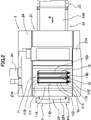
- FIG. FIG. 2 is a schematic plan view of the dough spreading device of FIG. 1
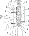
- 1 is a schematic enlarged front sectional view of a cleaning device according to a first embodiment of the present invention
- FIG. Fig. 2 is a schematic front cross-sectional view of a dough spreading device including a cleaning device according to a second embodiment of the present invention
- FIG. 8 is a schematic cross-sectional view of a dough spreading device including a cleaning device according to a third embodiment of the present invention, viewed from the upstream side in the direction of conveyance of the dough.
- FIG. 11 is a schematic front cross-sectional view of a dough spreading device including a cleaning device according to a fourth embodiment of the present invention
- FIG. 11 is a schematic front cross-sectional view of a dough spreading device including a cleaning device according to a fourth embodiment of the present invention
- FIG. 11 is a schematic front cross-sectional view of a dough spreading device including a modification of the cleaning device according to the fourth embodiment of the present invention
- FIG. 11 is a schematic front cross-sectional view of a dough spreading device including a modification of the cleaning device according to the fourth embodiment of the present invention
- FIG. 5 is a schematic front view of a dough spreading device including a modification of the cleaning device according to the second embodiment of the present invention
- the cleaning device 1 is a device for cleaning adhering matter W adhering to the surface 26A of the spreading roller 26 in the dough spreading device 2 that spreads the food dough D.
- the food dough D will be described as bread dough
- the adhering matter W will be described as dough dregs of bread dough and powder scattered on the surface of the dough.
- the dough spreading device 2 is a device for spreading the food dough D carried in from the upstream conveyor JC and carrying it out to the downstream conveyor KC. and a spreading device 22 arranged above the conveying device 21 .
- the conveying device 21 includes a first conveyor 23 having an endless conveyor belt 23A, a second conveyor 24 having an endless conveyor belt 24A disposed adjacently on the downstream side thereof, and a second conveyor 24 having an endless conveyor belt 24A adjacent thereto. and includes a third conveyor 25 with an endless conveyor belt 25A.
- Each of these three conveyors 23, 24, 25 has a facing surface facing the spreading device 22, and the facing surface of the first conveyor 23 and the facing surface of the second conveyor 24 are adjustable in angle.
- the conveying device 21 is configured to convey the fabric D in the conveying direction R shown in FIG.
- the spreading device 22 includes a plurality of spreading rollers 26 and a spreading roller driving device 27 that rotates (moves) the plurality of spreading rollers 26 along an endless elliptical track in the direction of arrow S shown in FIG.
- the spreading roller driving device 27 includes a pair of frames 27A, a pair of driving sprockets 27B, a pair of driven sprockets 27C, a pair of chains 27D, a plurality of spreading roller shafts 27E, and a pair of guide rails for the spreading rollers 26. 27F and drive motor M1.
- a pair of frames 27A are arranged above the pedestal 2A and on both the left and right sides of the conveying device 21.
- a driving sprocket 27B, a driven sprocket 27C, and a guide rail 27F are arranged inside each of the pair of frames 27A.
- a chain 27D is wound around the drive sprocket 27B and the driven sprocket 27C to form an elliptical orbit of the spreading roller 26.
- Both ends of the spreading roller shaft 27E are fixed to left and right chains 27D, respectively.
- a plurality of spreading roller shafts 27E are fixed to chains 27D at predetermined intervals.
- a pair of driving sprockets 27B and a pair of driven sprockets 27C are attached (fitted on) to a driving shaft and a driven shaft, respectively, and integrally circulated around a pair of left and right chains 27D by a driving motor M1 connected to the driving shaft ( movement).
- Each of the plurality of spreading rollers 26 is rotatably supported (pivotally supported) by a spreading roller shaft 27E and configured to rotate (move) in the direction of arrow S shown in FIG. 1 along the elliptical track of the chain 27D. be done.
- the spreading roller 26 is configured to spread the fabric D between the spreading roller 26 and the opposite surface of the conveying device 21 when it moves in the lower straight portion (spreading area SA) of the oval track
- the cleaning device 1 is configured to clean deposits W adhering to the surface 26A of the spreading roller 26 when it moves in the upper straight portion (cleaning area CA) of the elliptical track.
- the cleaning device 1 is arranged above the fabric spreading device 2 and includes a cleaning device main body 11, a cleaning member 13, an urging member 15, and a spreading roller rotating device 17.
- the cleaning device main body 11 includes a base 11A and a pair of side plates 11B and 11C.
- the base 11A is a plate-shaped member that extends (bridges) between the pair of frames 27A of the extension device 22 and is arranged on the upper end side thereof. is).
- the side plates 11B and 11C are plate-like members, and are arranged parallel to each other along the transport direction R and outside the rectangular hole 11D on the upper surface of the base 11A. That is, the cleaning device 1 is arranged along (corresponding to) the upper linear portion of the elliptical track around which the spreading roller 26 revolves.
- the cleaning member 13 is a belt-like (sheet-like) member, and includes one end 13A in the longitudinal direction and a cleaning portion 13B. It is desirable to be made of urethane having However, the material of the cleaning member 13 is not limited to this, and can be appropriately selected.
- the cleaning portion 13B has a cleaning surface 13C that contacts the surface 26A of the spreading roller 26. As shown in FIG. It is desirable that the cleaning surface 13C has an uneven shape.
- the uneven shape of the cleaning surface 13C is desirably a shape in which recesses (grooves) are formed (engraved) in a lattice shape, but is not limited to this, and for example, a shape in which recesses are formed (engraved) in parallel.
- the convex portion may have a shape of a truncated pyramid or a truncated cone.
- the shape, depth, width, etc. of the recesses and the shape, height, etc. of the protrusions are preferably selected as appropriate according to conditions such as the properties of the dough to be spread.
- One end 13A of the cleaning member 13 is fixed to the plate 13D.
- One end of the plate 13D is inserted into the mounting hole 11F of the side plate 11B and the other end of the plate 13D is inserted into the mounting groove 11G of the side plate 11C, and then fixed to the side plate 11C by the knob bolt 11E. .
- the knob bolt 11E By attaching and detaching the knob bolt 11E to and from the side plate 11C, the cleaning member 13 and the plate 13D can be integrally and easily detachably attached to the side plates 11B and 11C.
- one end portion 13A of the strip-shaped (sheet-shaped) cleaning member 13 is detachably fixed to the cleaning device main body 11 via a plate 13D, and the cleaning portion 13B passes through the rectangular hole 11D of the base 11A.
- cleaning surface 13C is configured to abut surface 26A of spreader roller 26, thereby cleaning surface 26A of spreader roller 26.
- FIG. FIG. 3 shows an example in which the cleaning section 13B abuts on three continuous spreading rollers 26 .
- the biasing member 15 is configured to press the cleaning portion 13B of the cleaning member 13 against the surface 26A of the spreading roller 26 by biasing it from the opposite side of the cleaning surface 13C.
- the biasing member 15 is belt-shaped (sheet-shaped), includes one end 15A in the longitudinal direction and the other biasing portion 15B, and is made of urethane having flexibility and elasticity. is desirable.
- the material of the biasing member 15 is not limited to this, and can be appropriately selected.
- the plate 15D is configured such that one end thereof is inserted into the mounting hole 11F of the side plate 11B and the other end thereof is inserted into the mounting groove 11G of the side plate 11C, and then fixed to the side plate 11C by knob bolts 11E. .
- the biasing member 15 and the plate 15D can be integrally and easily detachably attached to the side plates 11B and 11C.
- the biasing portion 15B has a biasing surface 15C that abuts against the surface (back side) opposite to the cleaning surface 13C, and is configured to press the cleaning portion 13B against the surface 26A of the spreading roller 26.
- one end portion 15A of the belt-like (sheet-like) biasing member 15 is detachably fixed to the cleaning device main body 11 via a plate 15D, and the biasing portion 15B is a rectangular hole 11D of the base 11A. and bias the cleaning portion 13B from the opposite (back) side of the cleaning surface 13C so that the cleaning surface 13C is configured to press against the surface 26A of the spreader roller 26.
- the biasing portion 15B is a rectangular hole 11D of the base 11A. and bias the cleaning portion 13B from the opposite (back) side of the cleaning surface 13C so that the cleaning surface 13C is configured to press against the surface 26A of the spreader roller 26.
- the method of attaching and detaching the cleaning member 13 and the urging member 15 is not limited to the configuration described above, and may be, for example, a fixing method using a toggle clamp, and an operator can appropriately select a configuration that allows easy attachment and detachment.
- the flexibility of the cleaning member 13 can be varied by selecting its material and thickness, thereby varying the amount of deflection of the cleaning member 13 along the surface 26A of the spreader roller 26 and the The strength of contact with the spreading roller 26 can be changed.
- the plate 13D that is, one end 13A of the cleaning member 13
- the strength with which the cleaning member 13 contacts the spreading roller 26 may be changed by changing the direction (angle) of the plate 13D and fixing it.
- the number of biasing members 15 is not limited to this and can be changed as appropriate.
- the flexibility of the biasing member 15 can be changed by selecting its material and thickness, thereby changing the strength with which the cleaning surface 13C of the cleaning section 13B is pressed against the spreading roller 26. be able to.
- the cleaning member 13 may be biased by the weight of the biasing portion 15B.
- the spreading roller rotating device 17 is a device that rotates (rotates) the spreading roller 26 when the cleaning member 13 moves in the cleaning area CA where the cleaning member 13 contacts the spreading roller 26 and cleans the surface 26A thereof.
- the friction plate 17A generally has a rectangular parallelepiped shape, and slopes are formed at both ends in the longitudinal direction.
- the pair of friction plates 17A are arranged parallel to each other along the transport direction R at positions in contact with both ends of the spreading roller 26 on the upper surfaces of the pair of guide rails 27F. While the spreading roller 26 moving (revolving) in the direction of arrow S shown in FIG.
- the roller 26 can be rotated (rotated) in the direction of arrow T shown in FIG. 3 with respect to the spreading roller shaft 27E.
- the friction plate 17A is: It is desirable to be made of a material such as rubber having a relatively large coefficient of friction.
- the spreading roller rotating device 17 is not limited to the configuration of the present embodiment, but by arranging rack gears instead of the rubber friction plates 17A, providing gears at both ends of the spreading roller 26, and engaging the rack gears with the gears. , the spreading roller 26 moving in the cleaning area CA may be rotated (rotated).
- the range in which the spreading roller 26 is rotated (rotated) by the spreading roller rotating device 17 is preferably substantially the same as or longer than the cleaning area CA. There may be.
- a continuous food dough D is conveyed to the dough spreading device 2 from a dough feeding device (not shown) arranged on the upstream side.
- the food dough D is spread between the spreading roller 26 and the facing surface of the conveying device 21 in the lower straight portion (spreading area) SA of the elliptical track, and is carried out to the forming device (not shown) on the downstream side.
- the cleaning device 1 cleans the adhering matter W adhering to the surface 26A of the spreading roller 26 .
- the cleaning member 13 deforms so as to bend along the surface 26A of the spreading roller 26, and the cleaning surface 13C comes into surface contact with the portion of the spreading roller 26 located above the surface 26A.
- the spreading roller 26 moves in the direction of the arrow T shown in FIG. rotate in the direction That is, the moving (orbiting) and rotating (rotating) surface 26A slides in surface contact with the cleaning surface 13C, so that the cleaning surface 13C can clean the entire circumference of the surface 26A. Further, the cleaning surface 13C of the cleaning member 13 is urged by the urging member 15 toward the spreading roller 26 from the rear side thereof and is strongly pressed against the surface 26A, thereby spreading the adhering matter W over the entire circumference of the surface 26A. It can be crossed and cleaned efficiently.
- the friction plate 17A has inclined surfaces on the upstream side and the downstream side in the moving direction (the direction of the arrow S) of the spreading roller 26, when the spreading roller 26 moves from the guide rail 27F to the friction plate 17A, In addition, the impact when moving from the friction plate 17A to the guide rail 27F can be mitigated, and noise generation can be suppressed.
- the cleaning surface 13C of the cleaning member 13 is in surface contact with the surface 26A of the spreading roller 26 that rotates while revolving (moving) on an oval orbit. W can be cleaned efficiently.
- the cleaning member 13 can be easily attached and detached, and the cleaning member 13 itself can be cleaned easily, so that the burden on the operator can be reduced.
- the cleaning device 3 is a device for cleaning the adhering matter W adhering to the surface 26A of the spreading roller 26 in the dough spreading device 4 for spreading the food dough D.
- the dough spreading device 2 of the first embodiment is a device in which the spreading roller 26 revolves (moves) on an oval track, but in the fabric spreading device 4 of the present embodiment, the spreading roller 26 revolves (moves) on a circular track. ).
- the dough spreading device 4 includes a frame 4A, a conveying device 41 attached to the frame 4A, and a spreading device 42 arranged above the conveying device 41.
- the conveying device 41 includes a first conveyor 43, a large-diameter roller 44 arranged adjacently on the downstream side thereof, and a second conveyor 45 arranged adjacently on the downstream side thereof.
- the spreading device 42 includes a plurality of spreading rollers 26 and a spreading roller driving device 47 that rotates (moves) the plurality of spreading rollers 26 along an endless circular track in the direction of arrow S shown in FIG.
- the spreader roller driving device 47 includes a pair of frames 47A, a drive shaft 47B, a pair of roller bases 47C and 47D, a plurality of spreader roller shafts 27E, and a drive motor (not shown).
- the spreading roller 26 and the spreading roller shaft 27E are integrally fixed.
- a pair of frames 47A are arranged on both the left and right sides of the conveying device 41 above the pedestal 4A.
- the pair of frames 47A rotatably supports a drive shaft 47B on their facing inner sides, and the drive shaft 47B is inserted (passed through) and fixed to a pair of roller bases 47C and 47D.
- a pair of roller bases 47C and 47D rotatably support eight spreading roller shafts 27E between them at equal intervals in the circumferential direction.
- Eight gears 47E are fixed (externally fitted) to the ends of the spreading roller shafts 27E on the roller base 47D side, and mesh with gears 47F concentrically and rotatably attached to the drive shaft 47B. .
- a first drive motor is provided to drive the drive shaft 47B and another second drive motor to drive the gear 47F so that the spreader roller 26 moves along a circular orbit as indicated by the arrow S shown in FIG. It is possible to rotate (rotate) in the direction of the arrow T while going around (moving) in the direction.
- Each of the plurality of spreading rollers 26 is configured to spread the fabric between the spreading rollers 26 and the facing surface of the conveying device 41 when moving in the lower portion of the circular path (spreading area SA).
- the cleaning device 3 is configured to clean deposits W adhering to the surface 26A of the spreading roller 26 when moving the upper portion (cleaning area CA) of the track.
- the cleaning device 3 is arranged above the dough spreading device 4 and includes a cleaning device main body 11 , a cleaning member 13 , an urging member 15 and a spreading roller rotating device 37 .
- the spreading roller rotating device 37 is configured (also used) by the gears 47E and 47F described above and a second drive motor that drives the gear 47F.
- the cleaning member 13 and the biasing member 15 are flexible, they can be deformed according to the surface 26A of the spreading roller 26 that revolves (moves) in a circular orbit, so that the cleaning surface 13C is spread. The entire circumference of the surface 26A of the roller 26 can be cleaned.
- FIG. 5 is a cross-sectional view of the dough spreading device 6 as seen from the upstream side in the conveying direction.
- the cleaning device 5 is a device for cleaning the adhering matter W adhering to the surface 66A of the spreading roller 66 in the dough spreading device 6 that spreads the food dough D.
- the stretching rollers 26 revolve around an oval orbit. It is a device that reciprocates (moves) on a straight track.
- the dough spreading device 6 has a frame 6A extending in the width direction above the conveying device 61.
- the dough spreading device 6 includes a slider 6B, a rack gear 6C, and a pinion gear 6D inside a frame 6A. It is configured.
- the rack gear 6C is fixed to the frame 6A.
- the pinion gear 6D is fixed (inserted) to an upper shaft 6E rotatably supported by the slider 6B, and meshes with the rack gear 6C.
- an idler gear 6F is fixed (outer fitted) to the upper shaft 6E.
- a spreading roller 66 arranged at the lower portion of the slider 6B is fixed (inserted) to a lower shaft 6G rotatably supported by the slider 6B, and a gear 6H fixed (outerly fitted) to the lower shaft 6G is an idler gear 6F. is engaged with
- the spreading roller 66 alternately rotates counterclockwise and clockwise while reciprocating integrally with the slider 6B.
- the cleaning device 5 is arranged in the fabric spreading device 6 and includes a cleaning device main body 11 , a cleaning member 53 , three urging members 55 and a spreading roller rotating device 57 .
- the base 11A of the cleaning device main body 11 is a plate-shaped member arranged on the lower surface of the frame 6A, and has (is drilled with) a rectangular hole 11D in its central portion.
- the side plates 11B and 11C are plate-shaped members, which extend in the width direction and are arranged parallel to each other on the upper surface of the base 11A.
- the cleaning member 53 is a belt-like (sheet-like) member similar to the cleaning member 13 of the first embodiment, but in this embodiment both ends 53A of the cleaning member 53 are fixed to plates 53D. ing.
- the plate 53D has the same configuration as the plate 13D of the first embodiment, and is fixed to the pair of side plates 11B and 11C in an easily attachable and detachable manner. That is, both ends 53A of the strip-shaped cleaning member 53 are detachably fixed to the cleaning device main body 11 via a plate 53D, and a cleaning portion 53B between both ends 53A is formed by a rectangular hole in the base 11A. 11D, the cleaning surface 53C of the cleaning portion 53B is configured to abut the upper portion of the surface 66A of the spreader roller 66, thereby cleaning the surface 66A of the spreader roller 66. As shown in FIG.
- the three biasing members 55 are arranged along the width direction inside the hanging cleaning member 53 .
- the biasing member 55 is a member similar to the biasing member 15 of the first embodiment, but in this embodiment both ends 55A of the biasing member 55 are each fixed to a plate 55D to form a cleaning member. It is fixed to the pair of side plates 11B and 11C in a manner similar to 53 so that it can be easily attached and detached. Therefore, in this embodiment, the biasing portion 55B of the biasing member 55 is in a state of being curved downward and suspended, and the biasing surface 55C of the biasing portion 55B is the surface opposite to the cleaning surface 53C (back side). ), thereby pressing the cleaning portion 53B against the surface 66A of the spreading roller 66. As shown in FIG.
- both ends 55A of the urging member 55 are detachably fixed to the cleaning device main body 11 via a plate 55D, and the urging portion 55B hangs down to urge the cleaning portion 53B from the back side, thereby , the cleaning surface 53C is configured to press against the surface 66A of the spreader roller 66.
- the spreading roller rotating device 57 is configured (also used) by the above-described rack gear 6C, pinion gear 6D, and a drive motor for driving them.
- a continuous food dough D is conveyed to the dough spreading device 6 from a dough supplying device (not shown) arranged on the upstream side.
- the food dough D is spread between the spreading rollers 66 that reciprocate in the width direction and the facing surface of the conveying device 61, and is carried out to a forming device (not shown) on the downstream side.
- the cleaning device 5 cleans the adhering matter W adhering to the surface 66A of the spreading roller 66 that rotates while reciprocating on a linear track. Since both ends 53A of the cleaning member 53 are fixed to the cleaning device main body 11, the cleaning member 53 can be attached to the surface 66A of the spreading roller 66 without falling off regardless of which direction the spreading roller 66 is moving.
- the cleaning surface 53C is in surface contact with the surface 66A.
- the spreading roller 66 moves in the width direction (direction of arrow S) while rotating in the direction of arrow T shown in FIG. That is, since the rotating and moving surface 66A slides in surface contact with the cleaning surface 53C, the cleaning surface 53C can clean the entire circumference of the surface 66A. Further, the cleaning member 53 is urged by the urging member 55 toward the spreading roller 66 from its back side and is strongly pressed against the surface 66A, thereby efficiently cleaning the deposits over the entire circumference of the surface 66A. can do.
- the cleaning device 7 is a device for cleaning the adhering matter W adhering to the surface 86A of the spreading roller 86 in the dough spreading device 8 that spreads the food dough D. As shown in FIG. 6,
- the dough spreading device 8 is a device that spreads the food dough D flowing down from the hopper 8B and conveys it downstream by a conveying device 81 arranged below. 81 and a spreading device 82 .
- the spreading device 82 includes a pair of spreading rollers 86, and the spreading rollers 86 are eccentric rollers that are eccentric with respect to the rotating shaft.
- the pair of spreading rollers 86 are arranged parallel to each other at a predetermined interval and eccentrically oriented 180 degrees apart, and are configured to be interlocked with each other and rotated in opposite directions by a drive motor (not shown). Therefore, when the spreading rollers 86 are rotated, the gap between the pair of spreading rollers 86 repeatedly increases and decreases.
- the cleaning device 7 is arranged obliquely above the spreading roller 86 and includes a cleaning device main body 11 , a cleaning member 53 and an urging member 55 .
- the cleaning device main body 11 includes a base 11A and a pair of side plates 11B and 11C.
- the base 11A holds the plate-like side plates 11B and 11C so that they are arranged parallel to each other. Since the configurations of the cleaning member 53 and the biasing member 55 are the same as those of the third embodiment, description of such configurations is omitted.
- the food dough D is supplied from the hopper 8B to the spreading device 82, spread between a pair of spreading rollers 86, and conveyed by the conveying device 81 to a forming device (not shown) on the downstream side. Since the spreading roller 86 is eccentric with respect to the axis of rotation, the radius from the axis of rotation of the surface 86A of the spreading roller 86 in contact with the food dough D constantly varies.
- the cleaning portion 53B of the cleaning member 53 deforms according to the movement of the surface 86A of the spreading roller 86, thereby maintaining surface contact between the cleaning surface 53C and the surface 86A, and removing the deposit W adhering to the surface 86A of the spreading roller 86.
- the cleaning member 53 is urged by the urging member 55 toward the spreading roller 86 from the rear side thereof, the cleaning member 53 is strongly pressed against the surface 86A of the spreading roller 86, thereby causing the surface 86A of the spreading roller 86 to move around the entire circumference. It is possible to clean the deposits efficiently by cleaning over the entire surface.
- a spreading roller 96 arranged concentrically with the rotation axis and having a polygonal surface may be used instead of the spreading roller 86.
- the cleaning portion 53B of the cleaning member 53 deforms according to the movement of the surface 96A of the spreading roller 96, thereby maintaining the surface contact between the cleaning surface 53C and the surface 96A, and the surface of the spreading roller 96 Deposits W adhering to 96A are cleaned.
- the spreading roller is an elliptical roller or a roller having a wavy surface, the surface contact between the cleaning surface and the surface of the spreading roller can be prevented by appropriately selecting the material of the cleaning member. It is possible to maintain and clean deposits on the surface of the spreader roller.
- the circular orbit of the spreading roller is an oval or circular orbit
- the circular orbit of the spreading roller may be, for example, a triangular or elliptical circular orbit. Even in this case, it is possible for the cleaning member to come into surface contact along the surface of the spreading roller and clean the surface of the spreading roller.
- a configuration in which both ends 53A of the cleaning member 53 are detachably fixed to the cleaning device main body 11 may be adopted. With such a configuration, it is possible to clean deposits on the surface 26A of the spreading roller 26 regardless of the rotation (movement) direction and/or the rotation (rotation) direction of the spreading roller 26 .
Landscapes
- Life Sciences & Earth Sciences (AREA)
- Engineering & Computer Science (AREA)
- Food Science & Technology (AREA)
- Manufacturing And Processing Devices For Dough (AREA)
- Cleaning In General (AREA)
Priority Applications (5)
| Application Number | Priority Date | Filing Date | Title |
|---|---|---|---|
| JP2023517186A JP7686062B2 (ja) | 2021-04-28 | 2022-03-28 | 延展ローラの清掃装置 |
| KR1020237037073A KR20230162076A (ko) | 2021-04-28 | 2022-03-28 | 신장 롤러의 청소장치 |
| EP22795460.9A EP4331366A4 (en) | 2021-04-28 | 2022-03-28 | CLEANING DEVICE FOR STRETCHING ROLLER |
| US18/288,276 US12589413B2 (en) | 2021-04-28 | 2022-03-28 | Cleaning device for extension roller |
| CN202280031073.XA CN117255618B (zh) | 2021-04-28 | 2022-03-28 | 延展辊的清扫装置 |
Applications Claiming Priority (2)
| Application Number | Priority Date | Filing Date | Title |
|---|---|---|---|
| JP2021-075786 | 2021-04-28 | ||
| JP2021075786 | 2021-04-28 |
Publications (1)
| Publication Number | Publication Date |
|---|---|
| WO2022230543A1 true WO2022230543A1 (ja) | 2022-11-03 |
Family
ID=83848051
Family Applications (1)
| Application Number | Title | Priority Date | Filing Date |
|---|---|---|---|
| PCT/JP2022/015147 Ceased WO2022230543A1 (ja) | 2021-04-28 | 2022-03-28 | 延展ローラの清掃装置 |
Country Status (7)
| Country | Link |
|---|---|
| US (1) | US12589413B2 (https=) |
| EP (1) | EP4331366A4 (https=) |
| JP (1) | JP7686062B2 (https=) |
| KR (1) | KR20230162076A (https=) |
| CN (1) | CN117255618B (https=) |
| TW (1) | TWI829145B (https=) |
| WO (1) | WO2022230543A1 (https=) |
Citations (7)
| Publication number | Priority date | Publication date | Assignee | Title |
|---|---|---|---|---|
| JPS495264B1 (https=) * | 1970-03-23 | 1974-02-06 | ||
| JPS5225083A (en) | 1975-08-22 | 1977-02-24 | Rheon Automatic Machinery Co | Developing apparatus for confection or bread dough and like |
| JPS5938467U (ja) * | 1982-09-04 | 1984-03-10 | 株式会社リコー | 定着ロ−ラのクリ−ニング装置 |
| JPH0527639A (ja) * | 1991-07-24 | 1993-02-05 | Canon Inc | 定着装置 |
| JPH09172938A (ja) * | 1995-05-22 | 1997-07-08 | Rheon Autom Mach Co Ltd | パン生地等の連続的定量供給方法および装置 |
| JP2005348620A (ja) * | 2004-06-08 | 2005-12-22 | Kawata Shokuryo Kogyo Kk | うどん生地の圧延装置及び圧延方法 |
| JP2009050229A (ja) | 2007-08-29 | 2009-03-12 | Fuji Seisakusho:Kk | 製麺機 |
Family Cites Families (20)
| Publication number | Priority date | Publication date | Assignee | Title |
|---|---|---|---|---|
| JPS527639A (en) | 1975-07-08 | 1977-01-20 | Toshiba Corp | Digital output unit |
| US4192636A (en) | 1975-08-22 | 1980-03-11 | Rheon Automatic Machinery Co., Ltd. | Apparatus for stretching dough material |
| DE309005T1 (de) * | 1988-01-26 | 1989-08-03 | Machinefabriek C. Rijkaart B.V., Asperen | Verfahren zur herstellung von teig- und fettblaettchen. |
| JPH02227177A (ja) | 1989-01-17 | 1990-09-10 | Techno Roll Kk | 基材表面清掃装置 |
| CA2024054A1 (en) | 1989-09-01 | 1991-03-02 | Yoshichika Murakami | Cleaner for rotary bodies such as blanket cylinder, impression cylinder, ink supply rollers and the like |
| TW313513B (https=) | 1995-05-22 | 1997-08-21 | Reon Zidoki Kk | |
| MY115084A (en) | 1996-05-22 | 2003-03-31 | Rheon Automatic Machinery Co | Method and apparatus for continuously and quantitatively supplying bread dough |
| DE10329499B3 (de) * | 2003-06-30 | 2004-08-12 | Wandres Gmbh Micro-Cleaning | Vorrichtung zum Reinigen von Flächen mit einem ein Reinigungstrum aufweisenden Reinigungsgerät |
| ITPD20040130A1 (it) * | 2004-05-20 | 2004-08-20 | Marcato Spa | Macchina per pasta ad uso domestico migliorata. |
| KR20090050229A (ko) | 2007-11-15 | 2009-05-20 | 엘지이노텍 주식회사 | 액정표시장치 및 그 구동방법 |
| KR101307207B1 (ko) * | 2008-05-23 | 2013-09-11 | 레온 지도키 가부시키가이샤 | 식품생지의 절단방법 및 장치 |
| NL2013324B1 (en) | 2013-08-28 | 2016-01-08 | Laitram Llc | Flexible and adjustable roller scrapers. |
| US9545123B2 (en) * | 2013-11-12 | 2017-01-17 | Axis Automation Llc | Food topping dispenser with application roller for dusting food products |
| CN105059874A (zh) * | 2015-06-29 | 2015-11-18 | 候钧伦 | 用于皮带输送机的辊筒清洁装置 |
| CN205146747U (zh) * | 2015-11-30 | 2016-04-13 | 天津力神电池股份有限公司 | 锂离子电池极片碾压机的擦辊装置 |
| CN207414620U (zh) * | 2017-09-22 | 2018-05-29 | 四川川锅锅炉有限责任公司 | 用于滚轮架上滚轮的清扫结构 |
| CN107839659B (zh) * | 2017-11-02 | 2020-04-10 | 宁波中令清洁技术有限公司 | 一种汽车的清洁方法 |
| CN208562832U (zh) * | 2018-05-25 | 2019-03-01 | 常州市春晖纺织染整有限公司 | 一种刮毛刀机构及定型机轧车 |
| CN212150548U (zh) * | 2020-03-24 | 2020-12-15 | 江苏欧曼纺织科技有限公司 | 一种毛毯印花机传送带的清理装置 |
| CN112620192B (zh) * | 2020-12-16 | 2022-07-05 | 莱芜连云玻璃股份有限公司 | 一种便于维护的镀膜玻璃的镀膜胶辊自动清洗装置 |
-
2022
- 2022-03-28 WO PCT/JP2022/015147 patent/WO2022230543A1/ja not_active Ceased
- 2022-03-28 US US18/288,276 patent/US12589413B2/en active Active
- 2022-03-28 JP JP2023517186A patent/JP7686062B2/ja active Active
- 2022-03-28 CN CN202280031073.XA patent/CN117255618B/zh active Active
- 2022-03-28 KR KR1020237037073A patent/KR20230162076A/ko active Pending
- 2022-03-28 EP EP22795460.9A patent/EP4331366A4/en active Pending
- 2022-04-21 TW TW111115172A patent/TWI829145B/zh active
Patent Citations (7)
| Publication number | Priority date | Publication date | Assignee | Title |
|---|---|---|---|---|
| JPS495264B1 (https=) * | 1970-03-23 | 1974-02-06 | ||
| JPS5225083A (en) | 1975-08-22 | 1977-02-24 | Rheon Automatic Machinery Co | Developing apparatus for confection or bread dough and like |
| JPS5938467U (ja) * | 1982-09-04 | 1984-03-10 | 株式会社リコー | 定着ロ−ラのクリ−ニング装置 |
| JPH0527639A (ja) * | 1991-07-24 | 1993-02-05 | Canon Inc | 定着装置 |
| JPH09172938A (ja) * | 1995-05-22 | 1997-07-08 | Rheon Autom Mach Co Ltd | パン生地等の連続的定量供給方法および装置 |
| JP2005348620A (ja) * | 2004-06-08 | 2005-12-22 | Kawata Shokuryo Kogyo Kk | うどん生地の圧延装置及び圧延方法 |
| JP2009050229A (ja) | 2007-08-29 | 2009-03-12 | Fuji Seisakusho:Kk | 製麺機 |
Non-Patent Citations (1)
| Title |
|---|
| See also references of EP4331366A4 |
Also Published As
| Publication number | Publication date |
|---|---|
| US12589413B2 (en) | 2026-03-31 |
| TWI829145B (zh) | 2024-01-11 |
| CN117255618A (zh) | 2023-12-19 |
| EP4331366A1 (en) | 2024-03-06 |
| US20240215589A1 (en) | 2024-07-04 |
| KR20230162076A (ko) | 2023-11-28 |
| JPWO2022230543A1 (https=) | 2022-11-03 |
| JP7686062B2 (ja) | 2025-05-30 |
| CN117255618B (zh) | 2025-12-30 |
| TW202308516A (zh) | 2023-03-01 |
| EP4331366A4 (en) | 2024-11-13 |
Similar Documents
| Publication | Publication Date | Title |
|---|---|---|
| EP0312643B1 (en) | Conveyors | |
| US20100126831A1 (en) | Self cleaning belt conveyor | |
| US20190152707A1 (en) | Method and apparatus for driving a conveyor | |
| RU2360780C2 (ru) | Шлифовальное устройство для обработки поверхности | |
| US20130126313A1 (en) | Conveying device | |
| JP5171168B2 (ja) | 農産物の清浄装置 | |
| JPH0680229A (ja) | ベルトコンベア手段 | |
| JP6852718B2 (ja) | コンベヤ装置 | |
| WO2022230543A1 (ja) | 延展ローラの清掃装置 | |
| EP2114800B1 (en) | Manufacturing device for use with a vibratory conveyor, and method for manufacturing a product | |
| EP0826304B1 (en) | Apparatus for powdering bread dough being stretched | |
| HK40099030A (zh) | 延展辊的清扫装置 | |
| HK40099030B (zh) | 延展辊的清扫装置 | |
| JP4543485B2 (ja) | 無端チェーンコンベア清掃装置 | |
| JP6366967B2 (ja) | 粉体の払い方法及びその装置 | |
| JP7342347B2 (ja) | コンベヤ装置 | |
| JP6708908B2 (ja) | コンベア | |
| JP5489520B2 (ja) | 搬送装置 | |
| CN212173630U (zh) | 一种用于清扫输送带的毛刷辊支架 | |
| JP2009298015A (ja) | グリッパー清掃装置 | |
| JPS58150478A (ja) | ロ−ル式処理機の自動清掃装置 | |
| KR20250036814A (ko) | 박스 피복용 장치 | |
| JPH04338017A (ja) | ベルト搬送装置 | |
| US271932A (en) | smith | |
| JP4041285B2 (ja) | フィルタープレート及び塵芥除去装置 |
Legal Events
| Date | Code | Title | Description |
|---|---|---|---|
| 121 | Ep: the epo has been informed by wipo that ep was designated in this application |
Ref document number: 22795460 Country of ref document: EP Kind code of ref document: A1 |
|
| WWE | Wipo information: entry into national phase |
Ref document number: 2301006930 Country of ref document: TH |
|
| WWE | Wipo information: entry into national phase |
Ref document number: 18288276 Country of ref document: US |
|
| WWE | Wipo information: entry into national phase |
Ref document number: 202280031073.X Country of ref document: CN |
|
| ENP | Entry into the national phase |
Ref document number: 20237037073 Country of ref document: KR Kind code of ref document: A |
|
| WWE | Wipo information: entry into national phase |
Ref document number: 2023517186 Country of ref document: JP Ref document number: 1020237037073 Country of ref document: KR |
|
| WWE | Wipo information: entry into national phase |
Ref document number: 202327076721 Country of ref document: IN |
|
| WWE | Wipo information: entry into national phase |
Ref document number: 2022795460 Country of ref document: EP |
|
| NENP | Non-entry into the national phase |
Ref country code: DE |
|
| ENP | Entry into the national phase |
Ref document number: 2022795460 Country of ref document: EP Effective date: 20231128 |
|
| WWG | Wipo information: grant in national office |
Ref document number: 18288276 Country of ref document: US |