WO2022224910A1 - 自動車窓用合わせガラス、自動車、及び自動車窓用合わせガラスの製造方法 - Google Patents
自動車窓用合わせガラス、自動車、及び自動車窓用合わせガラスの製造方法 Download PDFInfo
- Publication number
- WO2022224910A1 WO2022224910A1 PCT/JP2022/017959 JP2022017959W WO2022224910A1 WO 2022224910 A1 WO2022224910 A1 WO 2022224910A1 JP 2022017959 W JP2022017959 W JP 2022017959W WO 2022224910 A1 WO2022224910 A1 WO 2022224910A1
- Authority
- WO
- WIPO (PCT)
- Prior art keywords
- glass plate
- glass
- laminated
- laminated glass
- automobile
- Prior art date
Links
- 239000005340 laminated glass Substances 0.000 title claims abstract description 53
- 238000004519 manufacturing process Methods 0.000 title claims description 14
- 239000011521 glass Substances 0.000 claims abstract description 183
- 230000006835 compression Effects 0.000 claims abstract description 11
- 238000007906 compression Methods 0.000 claims abstract description 11
- 238000000034 method Methods 0.000 claims description 19
- 238000001816 cooling Methods 0.000 claims description 17
- 238000005452 bending Methods 0.000 claims description 14
- 238000010438 heat treatment Methods 0.000 claims description 7
- 238000007599 discharging Methods 0.000 claims 1
- 229920005989 resin Polymers 0.000 description 15
- 239000011347 resin Substances 0.000 description 15
- 239000010410 layer Substances 0.000 description 12
- 239000007789 gas Substances 0.000 description 10
- 239000000463 material Substances 0.000 description 7
- 229920001971 elastomer Polymers 0.000 description 6
- 229920002554 vinyl polymer Polymers 0.000 description 6
- DHKHKXVYLBGOIT-UHFFFAOYSA-N acetaldehyde Diethyl Acetal Natural products CCOC(C)OCC DHKHKXVYLBGOIT-UHFFFAOYSA-N 0.000 description 5
- 238000009413 insulation Methods 0.000 description 5
- 230000002093 peripheral effect Effects 0.000 description 5
- 239000004372 Polyvinyl alcohol Substances 0.000 description 4
- 230000007547 defect Effects 0.000 description 4
- 238000009826 distribution Methods 0.000 description 4
- 229920002451 polyvinyl alcohol Polymers 0.000 description 4
- 150000001241 acetals Chemical class 0.000 description 3
- 239000000853 adhesive Substances 0.000 description 3
- 230000001070 adhesive effect Effects 0.000 description 3
- 239000005357 flat glass Substances 0.000 description 3
- 238000000465 moulding Methods 0.000 description 3
- 229920002037 poly(vinyl butyral) polymer Polymers 0.000 description 3
- 238000005496 tempering Methods 0.000 description 3
- 229920005992 thermoplastic resin Polymers 0.000 description 3
- ZTQSAGDEMFDKMZ-UHFFFAOYSA-N Butyraldehyde Chemical compound CCCC=O ZTQSAGDEMFDKMZ-UHFFFAOYSA-N 0.000 description 2
- 206010019196 Head injury Diseases 0.000 description 2
- 238000010521 absorption reaction Methods 0.000 description 2
- 239000011354 acetal resin Substances 0.000 description 2
- 238000007792 addition Methods 0.000 description 2
- 238000007664 blowing Methods 0.000 description 2
- 238000010586 diagram Methods 0.000 description 2
- 239000005038 ethylene vinyl acetate Substances 0.000 description 2
- 239000011229 interlayer Substances 0.000 description 2
- 230000035515 penetration Effects 0.000 description 2
- 229920001200 poly(ethylene-vinyl acetate) Polymers 0.000 description 2
- 229920001225 polyester resin Polymers 0.000 description 2
- 229920006324 polyoxymethylene Polymers 0.000 description 2
- 239000004814 polyurethane Substances 0.000 description 2
- 229920002635 polyurethane Polymers 0.000 description 2
- 229920006395 saturated elastomer Polymers 0.000 description 2
- 239000005368 silicate glass Substances 0.000 description 2
- HUAUNKAZQWMVFY-UHFFFAOYSA-M sodium;oxocalcium;hydroxide Chemical compound [OH-].[Na+].[Ca]=O HUAUNKAZQWMVFY-UHFFFAOYSA-M 0.000 description 2
- IJGRMHOSHXDMSA-UHFFFAOYSA-N Atomic nitrogen Chemical compound N#N IJGRMHOSHXDMSA-UHFFFAOYSA-N 0.000 description 1
- 229920000089 Cyclic olefin copolymer Polymers 0.000 description 1
- 239000006018 Li-aluminosilicate Substances 0.000 description 1
- 238000006124 Pilkington process Methods 0.000 description 1
- 229920012485 Plasticized Polyvinyl chloride Polymers 0.000 description 1
- IKHGUXGNUITLKF-XPULMUKRSA-N acetaldehyde Chemical compound [14CH]([14CH3])=O IKHGUXGNUITLKF-XPULMUKRSA-N 0.000 description 1
- 239000005358 alkali aluminosilicate glass Substances 0.000 description 1
- 239000005354 aluminosilicate glass Substances 0.000 description 1
- 229920001400 block copolymer Polymers 0.000 description 1
- 239000005385 borate glass Substances 0.000 description 1
- 239000005388 borosilicate glass Substances 0.000 description 1
- DQXBYHZEEUGOBF-UHFFFAOYSA-N but-3-enoic acid;ethene Chemical compound C=C.OC(=O)CC=C DQXBYHZEEUGOBF-UHFFFAOYSA-N 0.000 description 1
- 238000002788 crimping Methods 0.000 description 1
- 238000012217 deletion Methods 0.000 description 1
- 230000037430 deletion Effects 0.000 description 1
- 229910001873 dinitrogen Inorganic materials 0.000 description 1
- 238000005516 engineering process Methods 0.000 description 1
- 229920006244 ethylene-ethyl acrylate Polymers 0.000 description 1
- 238000007429 general method Methods 0.000 description 1
- 230000005484 gravity Effects 0.000 description 1
- 229920000554 ionomer Polymers 0.000 description 1
- 238000003754 machining Methods 0.000 description 1
- WSFSSNUMVMOOMR-NJFSPNSNSA-N methanone Chemical compound O=[14CH2] WSFSSNUMVMOOMR-NJFSPNSNSA-N 0.000 description 1
- 238000012986 modification Methods 0.000 description 1
- 230000004048 modification Effects 0.000 description 1
- 239000006060 molten glass Substances 0.000 description 1
- 239000004014 plasticizer Substances 0.000 description 1
- 229920000642 polymer Polymers 0.000 description 1
- 239000002952 polymeric resin Substances 0.000 description 1
- 238000012545 processing Methods 0.000 description 1
- 239000011342 resin composition Substances 0.000 description 1
- 238000007493 shaping process Methods 0.000 description 1
- 230000035939 shock Effects 0.000 description 1
- 239000002356 single layer Substances 0.000 description 1
- 239000000126 substance Substances 0.000 description 1
- 238000006467 substitution reaction Methods 0.000 description 1
Images


Classifications
-
- C—CHEMISTRY; METALLURGY
- C03—GLASS; MINERAL OR SLAG WOOL
- C03B—MANUFACTURE, SHAPING, OR SUPPLEMENTARY PROCESSES
- C03B27/00—Tempering or quenching glass products
- C03B27/04—Tempering or quenching glass products using gas
- C03B27/0404—Nozzles, blow heads, blowing units or their arrangements, specially adapted for flat or bent glass sheets
-
- B—PERFORMING OPERATIONS; TRANSPORTING
- B32—LAYERED PRODUCTS
- B32B—LAYERED PRODUCTS, i.e. PRODUCTS BUILT-UP OF STRATA OF FLAT OR NON-FLAT, e.g. CELLULAR OR HONEYCOMB, FORM
- B32B1/00—Layered products having a non-planar shape
-
- B—PERFORMING OPERATIONS; TRANSPORTING
- B32—LAYERED PRODUCTS
- B32B—LAYERED PRODUCTS, i.e. PRODUCTS BUILT-UP OF STRATA OF FLAT OR NON-FLAT, e.g. CELLULAR OR HONEYCOMB, FORM
- B32B17/00—Layered products essentially comprising sheet glass, or glass, slag, or like fibres
- B32B17/06—Layered products essentially comprising sheet glass, or glass, slag, or like fibres comprising glass as the main or only constituent of a layer, next to another layer of a specific material
- B32B17/10—Layered products essentially comprising sheet glass, or glass, slag, or like fibres comprising glass as the main or only constituent of a layer, next to another layer of a specific material of synthetic resin
- B32B17/10005—Layered products essentially comprising sheet glass, or glass, slag, or like fibres comprising glass as the main or only constituent of a layer, next to another layer of a specific material of synthetic resin laminated safety glass or glazing
- B32B17/10009—Layered products essentially comprising sheet glass, or glass, slag, or like fibres comprising glass as the main or only constituent of a layer, next to another layer of a specific material of synthetic resin laminated safety glass or glazing characterized by the number, the constitution or treatment of glass sheets
- B32B17/10036—Layered products essentially comprising sheet glass, or glass, slag, or like fibres comprising glass as the main or only constituent of a layer, next to another layer of a specific material of synthetic resin laminated safety glass or glazing characterized by the number, the constitution or treatment of glass sheets comprising two outer glass sheets
-
- B—PERFORMING OPERATIONS; TRANSPORTING
- B32—LAYERED PRODUCTS
- B32B—LAYERED PRODUCTS, i.e. PRODUCTS BUILT-UP OF STRATA OF FLAT OR NON-FLAT, e.g. CELLULAR OR HONEYCOMB, FORM
- B32B17/00—Layered products essentially comprising sheet glass, or glass, slag, or like fibres
- B32B17/06—Layered products essentially comprising sheet glass, or glass, slag, or like fibres comprising glass as the main or only constituent of a layer, next to another layer of a specific material
- B32B17/10—Layered products essentially comprising sheet glass, or glass, slag, or like fibres comprising glass as the main or only constituent of a layer, next to another layer of a specific material of synthetic resin
- B32B17/10005—Layered products essentially comprising sheet glass, or glass, slag, or like fibres comprising glass as the main or only constituent of a layer, next to another layer of a specific material of synthetic resin laminated safety glass or glazing
- B32B17/1055—Layered products essentially comprising sheet glass, or glass, slag, or like fibres comprising glass as the main or only constituent of a layer, next to another layer of a specific material of synthetic resin laminated safety glass or glazing characterized by the resin layer, i.e. interlayer
- B32B17/10761—Layered products essentially comprising sheet glass, or glass, slag, or like fibres comprising glass as the main or only constituent of a layer, next to another layer of a specific material of synthetic resin laminated safety glass or glazing characterized by the resin layer, i.e. interlayer containing vinyl acetal
-
- B—PERFORMING OPERATIONS; TRANSPORTING
- B32—LAYERED PRODUCTS
- B32B—LAYERED PRODUCTS, i.e. PRODUCTS BUILT-UP OF STRATA OF FLAT OR NON-FLAT, e.g. CELLULAR OR HONEYCOMB, FORM
- B32B17/00—Layered products essentially comprising sheet glass, or glass, slag, or like fibres
- B32B17/06—Layered products essentially comprising sheet glass, or glass, slag, or like fibres comprising glass as the main or only constituent of a layer, next to another layer of a specific material
- B32B17/10—Layered products essentially comprising sheet glass, or glass, slag, or like fibres comprising glass as the main or only constituent of a layer, next to another layer of a specific material of synthetic resin
- B32B17/10005—Layered products essentially comprising sheet glass, or glass, slag, or like fibres comprising glass as the main or only constituent of a layer, next to another layer of a specific material of synthetic resin laminated safety glass or glazing
- B32B17/1055—Layered products essentially comprising sheet glass, or glass, slag, or like fibres comprising glass as the main or only constituent of a layer, next to another layer of a specific material of synthetic resin laminated safety glass or glazing characterized by the resin layer, i.e. interlayer
- B32B17/10788—Layered products essentially comprising sheet glass, or glass, slag, or like fibres comprising glass as the main or only constituent of a layer, next to another layer of a specific material of synthetic resin laminated safety glass or glazing characterized by the resin layer, i.e. interlayer containing ethylene vinylacetate
-
- B—PERFORMING OPERATIONS; TRANSPORTING
- B32—LAYERED PRODUCTS
- B32B—LAYERED PRODUCTS, i.e. PRODUCTS BUILT-UP OF STRATA OF FLAT OR NON-FLAT, e.g. CELLULAR OR HONEYCOMB, FORM
- B32B17/00—Layered products essentially comprising sheet glass, or glass, slag, or like fibres
- B32B17/06—Layered products essentially comprising sheet glass, or glass, slag, or like fibres comprising glass as the main or only constituent of a layer, next to another layer of a specific material
- B32B17/10—Layered products essentially comprising sheet glass, or glass, slag, or like fibres comprising glass as the main or only constituent of a layer, next to another layer of a specific material of synthetic resin
- B32B17/10005—Layered products essentially comprising sheet glass, or glass, slag, or like fibres comprising glass as the main or only constituent of a layer, next to another layer of a specific material of synthetic resin laminated safety glass or glazing
- B32B17/10807—Making laminated safety glass or glazing; Apparatus therefor
- B32B17/10889—Making laminated safety glass or glazing; Apparatus therefor shaping the sheets, e.g. by using a mould
-
- B—PERFORMING OPERATIONS; TRANSPORTING
- B32—LAYERED PRODUCTS
- B32B—LAYERED PRODUCTS, i.e. PRODUCTS BUILT-UP OF STRATA OF FLAT OR NON-FLAT, e.g. CELLULAR OR HONEYCOMB, FORM
- B32B17/00—Layered products essentially comprising sheet glass, or glass, slag, or like fibres
- B32B17/06—Layered products essentially comprising sheet glass, or glass, slag, or like fibres comprising glass as the main or only constituent of a layer, next to another layer of a specific material
- B32B17/10—Layered products essentially comprising sheet glass, or glass, slag, or like fibres comprising glass as the main or only constituent of a layer, next to another layer of a specific material of synthetic resin
- B32B17/10005—Layered products essentially comprising sheet glass, or glass, slag, or like fibres comprising glass as the main or only constituent of a layer, next to another layer of a specific material of synthetic resin laminated safety glass or glazing
- B32B17/10807—Making laminated safety glass or glazing; Apparatus therefor
- B32B17/10899—Making laminated safety glass or glazing; Apparatus therefor by introducing interlayers of synthetic resin
- B32B17/10935—Making laminated safety glass or glazing; Apparatus therefor by introducing interlayers of synthetic resin as a preformed layer, e.g. formed by extrusion
-
- B—PERFORMING OPERATIONS; TRANSPORTING
- B32—LAYERED PRODUCTS
- B32B—LAYERED PRODUCTS, i.e. PRODUCTS BUILT-UP OF STRATA OF FLAT OR NON-FLAT, e.g. CELLULAR OR HONEYCOMB, FORM
- B32B27/00—Layered products comprising a layer of synthetic resin
- B32B27/18—Layered products comprising a layer of synthetic resin characterised by the use of special additives
- B32B27/22—Layered products comprising a layer of synthetic resin characterised by the use of special additives using plasticisers
-
- B—PERFORMING OPERATIONS; TRANSPORTING
- B32—LAYERED PRODUCTS
- B32B—LAYERED PRODUCTS, i.e. PRODUCTS BUILT-UP OF STRATA OF FLAT OR NON-FLAT, e.g. CELLULAR OR HONEYCOMB, FORM
- B32B27/00—Layered products comprising a layer of synthetic resin
- B32B27/30—Layered products comprising a layer of synthetic resin comprising vinyl (co)polymers; comprising acrylic (co)polymers
- B32B27/306—Layered products comprising a layer of synthetic resin comprising vinyl (co)polymers; comprising acrylic (co)polymers comprising vinyl acetate or vinyl alcohol (co)polymers
-
- B—PERFORMING OPERATIONS; TRANSPORTING
- B32—LAYERED PRODUCTS
- B32B—LAYERED PRODUCTS, i.e. PRODUCTS BUILT-UP OF STRATA OF FLAT OR NON-FLAT, e.g. CELLULAR OR HONEYCOMB, FORM
- B32B5/00—Layered products characterised by the non- homogeneity or physical structure, i.e. comprising a fibrous, filamentary, particulate or foam layer; Layered products characterised by having a layer differing constitutionally or physically in different parts
- B32B5/14—Layered products characterised by the non- homogeneity or physical structure, i.e. comprising a fibrous, filamentary, particulate or foam layer; Layered products characterised by having a layer differing constitutionally or physically in different parts characterised by a layer differing constitutionally or physically in different parts, e.g. denser near its faces
- B32B5/142—Variation across the area of the layer
-
- B—PERFORMING OPERATIONS; TRANSPORTING
- B32—LAYERED PRODUCTS
- B32B—LAYERED PRODUCTS, i.e. PRODUCTS BUILT-UP OF STRATA OF FLAT OR NON-FLAT, e.g. CELLULAR OR HONEYCOMB, FORM
- B32B7/00—Layered products characterised by the relation between layers; Layered products characterised by the relative orientation of features between layers, or by the relative values of a measurable parameter between layers, i.e. products comprising layers having different physical, chemical or physicochemical properties; Layered products characterised by the interconnection of layers
- B32B7/04—Interconnection of layers
- B32B7/12—Interconnection of layers using interposed adhesives or interposed materials with bonding properties
-
- B—PERFORMING OPERATIONS; TRANSPORTING
- B60—VEHICLES IN GENERAL
- B60J—WINDOWS, WINDSCREENS, NON-FIXED ROOFS, DOORS, OR SIMILAR DEVICES FOR VEHICLES; REMOVABLE EXTERNAL PROTECTIVE COVERINGS SPECIALLY ADAPTED FOR VEHICLES
- B60J1/00—Windows; Windscreens; Accessories therefor
-
- C—CHEMISTRY; METALLURGY
- C03—GLASS; MINERAL OR SLAG WOOL
- C03B—MANUFACTURE, SHAPING, OR SUPPLEMENTARY PROCESSES
- C03B27/00—Tempering or quenching glass products
- C03B27/04—Tempering or quenching glass products using gas
- C03B27/0413—Stresses, e.g. patterns, values or formulae for flat or bent glass sheets
-
- C—CHEMISTRY; METALLURGY
- C03—GLASS; MINERAL OR SLAG WOOL
- C03B—MANUFACTURE, SHAPING, OR SUPPLEMENTARY PROCESSES
- C03B27/00—Tempering or quenching glass products
- C03B27/04—Tempering or quenching glass products using gas
- C03B27/044—Tempering or quenching glass products using gas for flat or bent glass sheets being in a horizontal position
-
- B—PERFORMING OPERATIONS; TRANSPORTING
- B32—LAYERED PRODUCTS
- B32B—LAYERED PRODUCTS, i.e. PRODUCTS BUILT-UP OF STRATA OF FLAT OR NON-FLAT, e.g. CELLULAR OR HONEYCOMB, FORM
- B32B2307/00—Properties of the layers or laminate
- B32B2307/40—Properties of the layers or laminate having particular optical properties
- B32B2307/412—Transparent
-
- B—PERFORMING OPERATIONS; TRANSPORTING
- B32—LAYERED PRODUCTS
- B32B—LAYERED PRODUCTS, i.e. PRODUCTS BUILT-UP OF STRATA OF FLAT OR NON-FLAT, e.g. CELLULAR OR HONEYCOMB, FORM
- B32B2307/00—Properties of the layers or laminate
- B32B2307/50—Properties of the layers or laminate having particular mechanical properties
- B32B2307/54—Yield strength; Tensile strength
-
- B—PERFORMING OPERATIONS; TRANSPORTING
- B32—LAYERED PRODUCTS
- B32B—LAYERED PRODUCTS, i.e. PRODUCTS BUILT-UP OF STRATA OF FLAT OR NON-FLAT, e.g. CELLULAR OR HONEYCOMB, FORM
- B32B2307/00—Properties of the layers or laminate
- B32B2307/50—Properties of the layers or laminate having particular mechanical properties
- B32B2307/558—Impact strength, toughness
-
- B—PERFORMING OPERATIONS; TRANSPORTING
- B32—LAYERED PRODUCTS
- B32B—LAYERED PRODUCTS, i.e. PRODUCTS BUILT-UP OF STRATA OF FLAT OR NON-FLAT, e.g. CELLULAR OR HONEYCOMB, FORM
- B32B2307/00—Properties of the layers or laminate
- B32B2307/70—Other properties
- B32B2307/732—Dimensional properties
- B32B2307/737—Dimensions, e.g. volume or area
- B32B2307/7375—Linear, e.g. length, distance or width
- B32B2307/7376—Thickness
-
- B—PERFORMING OPERATIONS; TRANSPORTING
- B32—LAYERED PRODUCTS
- B32B—LAYERED PRODUCTS, i.e. PRODUCTS BUILT-UP OF STRATA OF FLAT OR NON-FLAT, e.g. CELLULAR OR HONEYCOMB, FORM
- B32B2605/00—Vehicles
- B32B2605/08—Cars
Definitions
- the present disclosure relates to laminated glass for automobile windows, automobiles, and methods for manufacturing laminated glass for automobile windows.
- Patent Document 1 when an impact is applied to the cowl louver and the windshield, the rear end of the cowl louver and the front end of the windshield, which are connected by a molding, are separated from each other, thereby causing a shock to a person. is disclosed.
- the laminated glass described in Patent Document 2 includes a first layer made of soda lime silicate glass, a second layer made of chemically strengthened alkali aluminosilicate glass, and the first layer and the second layer. and an adhesive interlayer that joins the layers.
- the convex side of the first layer (the side facing the exterior of the vehicle or building) has a surface compressive stress of 10-20 MPa. Also, the first layer has an edge compression greater than 25 MPa.
- the first glass sheet is heated to a temperature suitable for forming.
- a first glass sheet is deposited on a first bending tool.
- the edge of the first glass sheet is placed over the forming surface of the first bending tool.
- a shaping surface of the first bending tool is configured to provide a compression region and a tension region to the first glass sheet.
- a first glass sheet is formed on a first bending tool and a compressed region is formed at an edge of the first glass sheet.
- the compression region includes a first portion and a second portion. The width of the first portion is greater than the width of the second portion.
- Laminated glass for automobile windows such as windshields is required to break appropriately in order to reduce the impact on people when a car collides with a person such as a pedestrian.
- laminated glass for automobile windows is required to have a Head Injury Criterion (HIC) below a desired value.
- HIC Head Injury Criterion
- laminated glass for automobile windows is also required to have appropriate strength from the viewpoint of durability.
- One aspect of the present disclosure provides a technique for obtaining moderate durability while reducing the impact on people in the event of a collision between a car and a person.
- a laminated glass for automobile windows includes a first glass plate, an intermediate film, and a second glass plate in this order from the vehicle exterior to the vehicle interior.
- a first region having an edge compression of 21 MPa to 60 MPa and a second region having an edge compression of 8 MPa to 20 MPa are alternately arranged along the periphery of the first glass plate or the second glass plate.
- moderate durability can be obtained while reducing the impact on a person when a car and a person collide.
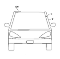
- FIG. 1 is a front view of an automobile provided with laminated glass according to one embodiment.
- FIG. 2 is a cross-sectional view showing part of the laminated glass according to one embodiment.
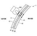
- FIG. 3 is a diagram showing an example of plane stress distribution generated in the cooling process after bending the glass sheet.
- FIG. 4 is a diagram showing an example of first regions and second regions alternately arranged along the periphery of the first glass plate.
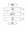
- FIG. 5 is a flowchart of a method for manufacturing laminated glass according to one embodiment.
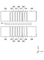
- FIG. 6 is a top view showing an example of a cooling device used in step S3 of FIG. 7 is a cross-sectional view of the cooling device of FIG. 6;
- an automobile 100 includes a laminated automobile window glass 1 and a vehicle body 2 including an opening to which the laminated automobile window glass 1 is attached.
- the laminated glass 1 for automobile windows is hereinafter also simply referred to as the laminated glass 1 .
- the laminated glass 1 is, for example, a windshield, but may be a window glass other than the windshield, such as a side glass, a rear glass, or a roof glass.
- the laminated glass 1 includes a first glass plate 10, an intermediate film 30, and a second glass plate 20 in this order from the vehicle exterior to the vehicle interior.
- the intermediate film 30 bonds the first glass plate 10 and the second glass plate 20 together.
- the first glass plate 10 has a first surface 11 that is an exterior surface of the vehicle and a second surface 12 that is an interior surface of the vehicle.
- the second glass plate 20 has a third surface 21 that is an exterior surface of the vehicle and a fourth surface 22 that is an interior surface of the vehicle.
- the first glass plate 10 and the second glass plate 20 may be made of the same material or different materials.
- the material of the first glass plate 10 and the second glass plate 20 is preferably inorganic glass.
- inorganic glass include soda lime silicate glass, aluminosilicate glass, borate glass, lithium aluminosilicate glass, and borosilicate glass.
- a method for forming the inorganic glass into a plate is not particularly limited, and for example, a float method.
- the first glass plate 10 and the second glass plate 20 may be untempered glass (raw glass).
- Untempered glass is glass obtained by molding molten glass into a plate shape and then slowly cooling it, and is glass that has not undergone tempering treatment such as air-cooling tempering treatment or chemical tempering treatment. Untempered glass is less likely to cause mesh-like or spider-web-like cracks or the like when broken upon impact, and can ensure the visibility of the occupant.
- the first glass plate 10 and the second glass plate 20 may have the same thickness or different thicknesses.
- the thickness of the first glass plate 10 is, for example, 1.1 mm or more and 3.5 mm or less.
- the thickness of the second glass plate 20 is 0.5 mm or more and 2.3 mm or less.
- the thickness of the entire laminated glass 1 is 2.3 mm or more and 8.0 mm or less.
- the material of the intermediate film 30 is not particularly limited, but is preferably a thermoplastic resin.
- Materials for the intermediate film 30 include plasticized polyvinyl acetal-based resin, plasticized polyvinyl chloride-based resin, saturated polyester-based resin, plasticized saturated polyester-based resin, polyurethane-based resin, plasticized polyurethane-based resin, and ethylene-vinyl acetate.
- Thermoplastic resins conventionally used for various purposes, such as polymer-based resins, ethylene-ethyl acrylate copolymer-based resins, cycloolefin polymer resins, and ionomer resins, can be mentioned.
- plasticized polyvinyl acetal resin is excellent in the balance of performance such as transparency, weather resistance, strength, adhesive strength, penetration resistance, impact energy absorption, moisture resistance, heat insulation, and sound insulation. is preferably used. You may use said thermoplastic resin individually or in combination of 2 or more types. “Plasticization” in the above-mentioned plasticized polyvinyl acetal resin means plasticization by addition of a plasticizer. The same applies to other plasticizing resins.
- the material of the intermediate film 30 may be a plasticizer-free resin such as an ethylene-vinyl acetate copolymer resin.
- the polyvinyl acetal-based resin include a polyvinyl formal resin obtained by reacting polyvinyl alcohol (PVA) and formaldehyde, a narrowly defined polyvinyl acetal-based resin obtained by reacting PVA and acetaldehyde, and PVA and n-butyraldehyde.
- Polyvinyl butyral resin (PVB) obtained by reacting, in particular, transparency, weather resistance, strength, adhesive strength, penetration resistance, impact energy absorption, moisture resistance, heat insulation, and sound insulation PVB is a suitable material because of its excellent balance of properties. In addition, you may use said resin individually or in combination of 2 or more types.
- the intermediate film 30 may have either a single-layer structure or a multi-layer structure.
- the intermediate film 30 may have functions other than adhesion.
- the intermediate film 30 may have one or more selected from a sound insulation layer, a colored transparent layer, an ultraviolet cut layer, an infrared cut layer, and the like.
- the thickness of the intermediate film 30 is 0.5 mm or more from the viewpoint of adhesiveness. Moreover, the thickness of the intermediate film 30 is 3 mm or less from the viewpoint of lightness and handleability.
- the thickness of the intermediate film 30 may be constant or may vary depending on the position. For example, when an image of a head-up display is projected onto the laminated glass 1, the thickness of the intermediate film 30 increases from the bottom to the top in order to suppress the occurrence of double images.
- the intermediate film 30 is formed in a wedge shape with a wedge angle of, for example, 1.0 mrad or less.
- the method for manufacturing the laminated glass 1 includes, for example, the following steps (A) to (C).
- (A) The first glass plate 10 and the second glass plate 20 are laminated with the intermediate film 30 interposed therebetween to produce a laminate.
- (B) The laminated body is placed inside a rubber bag, and the rubber bag is heated while the inside of the rubber bag is decompressed to bond the first glass plate 10 and the second glass plate 20 together with the intermediate film 30 .
- the air pressure inside the rubber bag is, for example, -100 kPa to -65 kPa based on the atmospheric pressure.
- the heating temperature of the rubber bag is, for example, 70.degree. C. to 110.degree.
- the laminated body taken out from the rubber bag is pressed under pressure of 0.6 MPa to 1.3 MPa while heating at 100°C to 150°C.
- An autoclave for example, is used for crimping.
- the method for manufacturing the laminated glass 1 may be a general method, and does not need to include the above step (C).
- the laminated glass 1 is, for example, wholly or partially curved so as to protrude outwardly of the vehicle.
- the laminated glass 1 is a double-curved glass curved in the front-rear direction and the vertical direction of the vehicle, but may be a single-curved glass curved only in the front-rear direction or the vertical direction.
- the radius of curvature of the laminated glass 1 is, for example, 200 mm to 300000 mm.
- the first glass plate 10 and the second glass plate 20 are bent before the above step (A). Bending is performed while the glass is softened by heating.
- the heating temperature of the glass during bending is, for example, 550.degree. C. to 700.degree.
- the first glass plate 10 and the second glass plate 20 may be bent separately, or may be overlapped and bent at the same time. Bending may include gravity forming, press forming, or the like, or may include both.
- the glass plates 10 and 20 are heated during bending and then cooled.
- the peripheral edges of the glass plates 10 and 20 tend to be cooled faster than the center of the glass plates 10 and 20 .
- compressive stress is generated in the peripheral edges of the glass plates 10 and 20 .
- a tensile stress is generated that balances the compressive stress.
- FIG. 3 shows an example of plane stress distribution generated in the cooling process after the glass plates 10 and 20 are bent.
- plane stress refers to plane stress measured using a photoelastic method, and the principal stress difference acting anisotropically in the plane direction (direction perpendicular to the plate thickness direction) (principal stress difference) is integrated over the entire sheet thickness direction.
- the plane stress of the glass plates 10 and 20 is measured, for example, by AGES-Meter manufactured by Orihara Seisakusho Co., Ltd.
- the plane stress of the glass plates 10, 20 is measured after the glass plates 10, 20 are bent.
- the glass plates 10 and 20 have an outer region in which a plane compressive stress is generated, an intermediate region in which a plane tensile stress is generated, and an inner region in which a plane compressive stress is generated in this order from the periphery of the glass plates 10 and 20 toward the inside.
- Including in The width of the outer region is, for example, 5 mm to 15 mm. Also, the width of the intermediate region is, for example, 20 mm to 50 mm.
- the plane compressive stress at the periphery of the glass plates 10 and 20 is also called edge compression E/C.
- the press-molded glass sheets 10, 20 have a higher E/C than the gravity-molded glass sheets 10, 20, for example, 21 MPa or more (preferably 25 MPa or more). Press molding is usually performed one by one.
- E/C1 is the maximum value of E/C in the first area A1 described later
- E/C2 is the minimum value of E/C in the second area A2 described later.
- the solid line indicates the plane stress distribution near the first region A1
- the dashed line indicates the plane stress distribution near the second region A2.
- the laminated glass 1 is required to break appropriately in order to reduce the impact on the person 200 such as a pedestrian when the automobile 100 collides with the person 200 such as a pedestrian.
- the laminated glass 1 is required to have a Head Injury Criterion (HIC) of a desired value or less (for example, 1000 or less, preferably 650 or less).
- HIC Head Injury Criterion
- the laminated glass 1 is also required to have appropriate strength from the viewpoint of durability.
- the laminated glass 1 When the automobile 100 and the person 200 collide, the laminated glass 1 is pushed from the outside of the vehicle toward the inside of the vehicle. As a result, a tensile stress is generated in the second surface 12 of the first glass plate 10, which is the vehicle-interior surface, and the second glass plate 20 cracks starting from the defects in the second surface 12. As shown in FIG. In addition, a tensile stress is generated on the fourth surface 22 of the second glass plate 20 on the vehicle interior side, and the second glass plate 20 cracks starting from the defect of the fourth surface 22 . In both the first glass plate 10 and the second glass plate 20, cracks extend from the inside of the vehicle to the outside of the vehicle.
- the strength of the glass plates 10 and 20 In order to reduce the HIC of the laminated glass 1, it is ideal to reduce the strength of the glass plates 10 and 20 at the collision point between the laminated glass 1 and the person 200.
- the strength of the glass plates 10 and 20 varies. There are cases where the glass plates 10 and 20 do not break at the point of impact. In this case, the impact stress propagates from the collision point of the glass plates 10, 20 toward the periphery. It is required that the glass sheets 10, 20 break when the impact stress reaches the periphery of the glass sheets 10, 20.
- the peripheral edges of the glass plates 10 and 20 are also required to have appropriate strength from the viewpoint of practicality and durability.
- the first regions A1 and the second regions A2 are alternately and repeatedly arranged along the periphery of the second glass plate 20 .
- the E/C is 21 MPa or more over the entire periphery of the glass plates 10 and 20
- defects such as processing scratches existing on the periphery of the glass plates 10 and 20 are difficult to open. Machining flaws are caused, for example, by chamfering.
- the second region A2 having an E/C of 20 MPa or less is partially provided, the defects existing at the periphery of the glass plates 10 and 20 are easily opened, and the glass plates 10 and 20 are suitable when the automobile 100 and the person 200 collide. split into Also, if the E/C of the second region A2 is 8 MPa or more, that is, if the E/C is 8 MPa or more over the entire peripheral edges of the glass plates 10 and 20, moderate durability can be obtained.
- first regions A1 and the second regions A2 are alternately and repeatedly arranged along the periphery of the first glass plate 10 will be described below.
- the case where the first regions A1 and the second regions A2 are alternately and repeatedly arranged along the periphery of the second glass plate 20 is the same, so the description is omitted.
- the first area A1 and the second area A2 may be provided on at least one of the first glass plate 10 and the second glass plate 20 .
- the first regions A1 and the second regions A2 may alternately and repeatedly line up along the entire periphery of the first glass plate 10, as shown in FIG. HIC can be reduced over the entire periphery of the first glass plate 10 .
- the second areas A2 may be provided in a range where the person 200 is likely to collide, and may be alternately and repeatedly arranged along a portion of the peripheral edge (for example, the lower edge) of the first glass plate 10 .
- the points with the lowest E/C in each second region A2 may be arranged along the periphery of the first glass plate 10 at intervals P of 30 mm to 200 mm. If the interval P is 200 mm or less, cracks are likely to occur near the collision point of the person 200 .
- the spacing P is preferably 100 mm or less. On the other hand, if the interval P is 10 mm or more, it is possible to prevent the structure of the cooling device 300, which will be described later, from becoming complicated.
- the distance P is preferably 30 mm or more.
- the second area A2 may be provided at the corner of the first glass plate 10.
- the second regions A2 may be provided at the four corners of the first glass plate 10.
- the corners of the laminated glass 1 are restrained from two directions and are particularly difficult to deform. In order to reduce the HIC at the corners of the laminated glass 1, it is effective to arrange the second regions A2 at the corners of the laminated glass 1.
- the first area A1 and the second area A2 are preferably provided on both the second glass plate 20 of the first glass plate 10. That is, the first regions A1 and the second regions A2 are alternately arranged along the periphery of the first glass plate 10, and the first regions A1 and the second regions A2 are arranged along the periphery of the second glass plate 20. are preferably arranged alternately. Both the first glass plate 10 and the second glass plate 20 are fragile and easily absorb impact.
- the second region A2 of the first glass plate 10 and the second region A2 of the second glass plate 20 are seen from a direction orthogonal to the first surface 11, which is the surface of the first glass plate 10 on the vehicle exterior side. may overlap.
- the first glass plate 10 and the second glass plate 20 break at points close to each other, so the impact is absorbed in a short time.
- the second region A2 of the first glass plate 10 and the second region A2 of the second glass plate 20 do not have to overlap completely, and may overlap at least partially.
- the method for manufacturing the laminated glass 1 has steps S1 to S3, for example.
- step S1 the glass plates 10 and 20 are heated.
- the heating temperature is, for example, 550.degree. C. to 700.degree.
- step S2 the heated glass plates 10 and 20 are bent. Bending includes, for example, press forming.
- step S3 the bent glass plates 10 and 20 are cooled with gas.
- the X-axis direction, Y-axis direction, and Z-axis direction are directions perpendicular to each other.
- the X-axis direction is the first horizontal direction
- the Y-axis direction is the second horizontal direction
- the Z-axis direction is the vertical direction.
- the cooling of the first glass plate 10 using the cooling device 300 will be described below. Since the cooling of the second glass plate 20 is the same as the cooling of the first glass plate 10, the explanation is omitted.
- the first glass plate 10 is temporarily stopped and cooled by the cooling device 300 while being transported in the Y-axis direction, for example.
- the cooling device 300 includes a first nozzle 310 longer than the first glass plate 10 in the X-axis direction and a second nozzle 320 shorter than the first glass plate 10 in the X-axis direction.
- the first nozzle 310 and the second nozzle 320 are, for example, blade-shaped and provided parallel to each other.
- the first nozzles 310 and the second nozzles 320 are alternately provided repeatedly in the Y-axis direction, and discharge gas in the Z-axis direction toward the first glass plate 10 . Air or nitrogen gas, for example, is used as the gas.
- the first nozzles 310 and the second nozzles 320 alternately form gas-blowing regions and non-gas-blowing regions on both edges of the first glass plate 10 in the X-axis direction. Areas to which gas is not blown are more difficult to cool than areas to which gas is blown, and tend to shrink later. As a result, variations in E/C occur at both edges of the first glass plate 10 in the X-axis direction.
- the area to which gas is blown corresponds to the first area A1, and the area to which gas is not blown corresponds to the second area A2.
- the cooling device 300 includes a plurality of third nozzles 330 spaced apart in the X-axis direction.
- the third nozzle 330 is, for example, blade-shaped.
- the third nozzle 330 discharges gas in the Z-axis direction toward one edge of the first glass plate 10 in the Y-axis direction.
- the plurality of third nozzles 330 alternately form areas where gas is blown and areas where gas is not blown on one edge of the first glass plate 10 in the Y-axis direction.
- the first regions A1 and the second regions A2 are alternately provided on one edge in the Y-axis direction of the first glass plate 10 .
- the third nozzle 330 is provided so as to be orthogonal to one side of the first glass plate 10 when viewed from the vertical direction.
- a boundary between the first area A1 and the second area A2 can be provided so as to be orthogonal to one side of the first glass plate 10 .
- the third nozzles 330 may be provided in two rows, one row being provided so as to overlap one edge of the first glass plate 10 in the Y-axis direction, and another row being provided so as to overlap the Y-axis direction edge of the first glass plate 10 . It may be provided so as to overlap the other edge in the axial direction.
- the first glass plate 10 may have two sides parallel to each other, and the third nozzles 330 may be provided so as to overlap one line on each side.
- a first nozzle 310 and a second nozzle 320 may be provided on both upper and lower sides of the first glass plate 10 .
- the third nozzles 330 may be provided on both upper and lower sides of the first glass plate 10 .
- the first glass plate 10 can be evenly cooled from both upper and lower sides.
- the present disclosure is not limited to the above embodiments.
- Various changes, modifications, substitutions, additions, deletions, and combinations are possible within the scope of the claims. These also naturally belong to the technical scope of the present disclosure.
Landscapes
- Chemical & Material Sciences (AREA)
- Engineering & Computer Science (AREA)
- Physics & Mathematics (AREA)
- Thermal Sciences (AREA)
- Materials Engineering (AREA)
- Organic Chemistry (AREA)
- Mechanical Engineering (AREA)
- Mathematical Physics (AREA)
- Joining Of Glass To Other Materials (AREA)
Abstract
Description
10 第1ガラス板
20 第2ガラス板
30 中間膜
A1 第1領域
A2 第2領域
Claims (10)
- 車外側から車内側に向けて、第1ガラス板と、中間膜と、第2ガラス板と、をこの順番で備える、自動車窓用合わせガラスであって、
前記第1ガラス板又は前記第2ガラス板の周縁に沿って、エッジコンプレッションが21MPa~60MPaである第1領域と、エッジコンプレッションが8MPa~20MPaである第2領域とが交互に繰り返し並ぶ、自動車窓用合わせガラス。 - 各前記第2領域においてエッジコンプレッションの最も低い点が、前記第1ガラス板又は前記第2ガラス板の周縁に沿って、30mm~200mmの間隔で並ぶ、請求項1に記載の自動車窓用合わせガラス。
- 前記第2領域は、前記第1ガラス板又は前記第2ガラス板の隅に設けられる、請求項1に記載の自動車窓用合わせガラス。
- 前記第1ガラス板の周縁に沿って前記第1領域と前記第2領域とが交互に繰り返し並び、且つ、前記第2ガラス板の周縁に沿って前記第1領域と前記第2領域とが交互に繰り返し並ぶ、請求項1に記載の自動車窓用合わせガラス。
- 前記第1ガラス板の車外側の面に直交する方向から見て、前記第1ガラス板の前記第2領域と、前記第2ガラス板の前記第2領域とが重なっている、請求項4に記載の自動車窓用合わせガラス。
- 請求項1~5のいずれか1項に記載の自動車窓用合わせガラスと、
前記自動車窓用合わせガラスが取り付けられる開口部を含む車体と、
を備える、自動車。 - 車外側から車内側に向けて、第1ガラス板と、中間膜と、第2ガラス板と、をこの順番で備える、自動車窓用合わせガラスの製造方法であって、
前記第1ガラス板又は前記第2ガラス板を加熱することと、前記加熱した前記第1ガラス板又は前記第2ガラス板を曲げ成形することと、前記曲げ成形した前記第1ガラス板又は前記第2ガラス板をガスで冷却することと、を有し、
前記第1ガラス板又は前記第2ガラス板よりも第1水平方向に長い第1ノズルと、前記第1ガラス板又は前記第2ガラス板よりも前記第1水平方向に短い第2ノズルとが、前記第1水平方向に対して垂直な第2水平方向に交互に繰り返し設けられ、前記第1ガラス板又は前記第2ガラス板に向けて鉛直方向に前記ガスを吐出する、自動車窓用合わせガラスの製造方法。 - 前記第1水平方向に間隔をおいて設けられる複数の第3ノズルが、前記第1ガラス板又は前記第2ガラス板の一辺に向けて鉛直方向に前記ガスを吐出する、請求項7に記載の自動車窓用合わせガラスの製造方法。
- 鉛直方向から見て、前記第3ノズルは、前記第1ガラス板又は前記第2ガラス板の前記一辺に直交するように設けられる、請求項8に記載の自動車窓用合わせガラスの製造方法。
- 車外側から車内側に向けて、第1ガラス板と、中間膜と、第2ガラス板と、をこの順番で備える、自動車窓用合わせガラスの製造方法であって、
前記第1ガラス板又は前記第2ガラス板を加熱することと、前記加熱した前記第1ガラス板又は前記第2ガラス板を曲げ成形することと、前記曲げ成形した前記第1ガラス板又は前記第2ガラス板をガスで冷却することと、を有し、
第1水平方向に間隔をおいて設けられる複数の第3ノズルが、前記第1ガラス板又は前記第2ガラス板の一辺に向けて鉛直方向に前記ガスを吐出し、
鉛直方向から見て、前記第3ノズルは、前記第1ガラス板又は前記第2ガラス板の前記一辺に直交するように設けられる、自動車窓用合わせガラスの製造方法。
Priority Applications (2)
| Application Number | Priority Date | Filing Date | Title |
|---|---|---|---|
| JP2023515449A JPWO2022224910A1 (ja) | 2021-04-20 | 2022-04-15 | |
| EP22791684.8A EP4328203A1 (en) | 2021-04-20 | 2022-04-15 | Laminated glass for automotive windows, automobile, and method for producing laminated glass for automotive windows |
Applications Claiming Priority (2)
| Application Number | Priority Date | Filing Date | Title |
|---|---|---|---|
| JP2021071147 | 2021-04-20 | ||
| JP2021-071147 | 2021-04-20 |
Publications (1)
| Publication Number | Publication Date |
|---|---|
| WO2022224910A1 true WO2022224910A1 (ja) | 2022-10-27 |
Family
ID=83723308
Family Applications (1)
| Application Number | Title | Priority Date | Filing Date |
|---|---|---|---|
| PCT/JP2022/017959 WO2022224910A1 (ja) | 2021-04-20 | 2022-04-15 | 自動車窓用合わせガラス、自動車、及び自動車窓用合わせガラスの製造方法 |
Country Status (3)
| Country | Link |
|---|---|
| EP (1) | EP4328203A1 (ja) |
| JP (1) | JPWO2022224910A1 (ja) |
| WO (1) | WO2022224910A1 (ja) |
Citations (10)
| Publication number | Priority date | Publication date | Assignee | Title |
|---|---|---|---|---|
| JPS5278226A (en) * | 1975-12-25 | 1977-07-01 | Asahi Glass Co Ltd | Laminated glass |
| JPS5645833A (en) * | 1979-09-18 | 1981-04-25 | Asahi Glass Co Ltd | Production of partially tempered glass plate |
| JPH0570158A (ja) * | 1991-09-10 | 1993-03-23 | Nippon Sheet Glass Co Ltd | 板ガラスの曲げ成形装置及び曲げ成形方法 |
| JP2002326830A (ja) * | 2001-04-27 | 2002-11-12 | Asahi Glass Co Ltd | 強化ガラス板 |
| WO2011096447A1 (ja) * | 2010-02-03 | 2011-08-11 | 旭硝子株式会社 | ガラス板及びガラス板の製造方法 |
| WO2015129605A1 (ja) * | 2014-02-25 | 2015-09-03 | 旭硝子株式会社 | ガラス板の徐冷方法及びガラス板 |
| JP6065221B2 (ja) | 2013-06-13 | 2017-01-25 | 日本ゼオン株式会社 | 合わせガラス板 |
| JP2017178641A (ja) * | 2016-03-28 | 2017-10-05 | 旭硝子株式会社 | 合わせガラス |
| JP2017213928A (ja) | 2016-05-30 | 2017-12-07 | トヨタ車体株式会社 | 車両のガラス接続構造 |
| JP2021071147A (ja) | 2019-10-30 | 2021-05-06 | 日本パワーファスニング株式会社 | 拡開式アンカー |
-
2022
- 2022-04-15 JP JP2023515449A patent/JPWO2022224910A1/ja active Pending
- 2022-04-15 EP EP22791684.8A patent/EP4328203A1/en active Pending
- 2022-04-15 WO PCT/JP2022/017959 patent/WO2022224910A1/ja active Application Filing
Patent Citations (10)
| Publication number | Priority date | Publication date | Assignee | Title |
|---|---|---|---|---|
| JPS5278226A (en) * | 1975-12-25 | 1977-07-01 | Asahi Glass Co Ltd | Laminated glass |
| JPS5645833A (en) * | 1979-09-18 | 1981-04-25 | Asahi Glass Co Ltd | Production of partially tempered glass plate |
| JPH0570158A (ja) * | 1991-09-10 | 1993-03-23 | Nippon Sheet Glass Co Ltd | 板ガラスの曲げ成形装置及び曲げ成形方法 |
| JP2002326830A (ja) * | 2001-04-27 | 2002-11-12 | Asahi Glass Co Ltd | 強化ガラス板 |
| WO2011096447A1 (ja) * | 2010-02-03 | 2011-08-11 | 旭硝子株式会社 | ガラス板及びガラス板の製造方法 |
| JP6065221B2 (ja) | 2013-06-13 | 2017-01-25 | 日本ゼオン株式会社 | 合わせガラス板 |
| WO2015129605A1 (ja) * | 2014-02-25 | 2015-09-03 | 旭硝子株式会社 | ガラス板の徐冷方法及びガラス板 |
| JP2017178641A (ja) * | 2016-03-28 | 2017-10-05 | 旭硝子株式会社 | 合わせガラス |
| JP2017213928A (ja) | 2016-05-30 | 2017-12-07 | トヨタ車体株式会社 | 車両のガラス接続構造 |
| JP2021071147A (ja) | 2019-10-30 | 2021-05-06 | 日本パワーファスニング株式会社 | 拡開式アンカー |
Also Published As
| Publication number | Publication date |
|---|---|
| JPWO2022224910A1 (ja) | 2022-10-27 |
| EP4328203A1 (en) | 2024-02-28 |
Similar Documents
| Publication | Publication Date | Title |
|---|---|---|
| EP3252022B1 (en) | Laminated glass | |
| EP2822761B1 (en) | High rigidity interlayers and light weight laminated multiple layer panels | |
| US4107366A (en) | Glass-plastic laminates | |
| JP6069213B2 (ja) | 積層窓ガラス | |
| TWI649286B (zh) | 輕量之混成式玻璃層疊物 | |
| TWI581960B (zh) | 輕量之混成式玻璃層疊物 | |
| KR102088678B1 (ko) | 곡면 접합 유리 및 곡면 접합 유리의 제조 방법 | |
| KR20170122132A (ko) | 접합 유리 및 접합 유리의 제조 방법 | |
| JPH10506367A (ja) | 板ガラスの端部強度の改善 | |
| WO2022224910A1 (ja) | 自動車窓用合わせガラス、自動車、及び自動車窓用合わせガラスの製造方法 | |
| US11034135B2 (en) | Laminated glass and method for manufacturing the same | |
| CN115003529A (zh) | 车辆用夹层玻璃、汽车、及车辆用夹层玻璃的制造方法 | |
| WO2022224908A1 (ja) | 車両用合わせガラスの製造方法及び自動車 | |
| WO2022224911A1 (ja) | 自動車窓用合わせガラス、及び自動車 | |
| JP2022014222A (ja) | 合わせガラスの製造方法 | |
| WO2022224912A1 (ja) | 自動車窓用合わせガラスの製造方法 | |
| EP4328205A1 (en) | Laminated glass for automobile windows, automobile, and method for manufacturing laminated glass for automobile windows | |
| JP2022165696A (ja) | 自動車窓用合わせガラス、及び自動車 | |
| JPWO2019208119A1 (ja) | 車両用軽量合わせガラス板の製造方法 | |
| CN115476556B (zh) | 玻璃组件、车辆 | |
| WO2023167285A1 (ja) | 自動車窓用合わせガラス、及び自動車 | |
| WO2022224909A1 (ja) | 車両用合わせガラス及び自動車 | |
| CN115448583B (zh) | 玻璃组件及其制备方法、车辆 | |
| JP2022160783A (ja) | 車両窓用合わせガラスの製造方法 | |
| JP2023011440A (ja) | 車両窓用合わせガラスの製造方法 |
Legal Events
| Date | Code | Title | Description |
|---|---|---|---|
| 121 | Ep: the epo has been informed by wipo that ep was designated in this application |
Ref document number: 22791684 Country of ref document: EP Kind code of ref document: A1 |
|
| WWE | Wipo information: entry into national phase |
Ref document number: 2023515449 Country of ref document: JP |
|
| WWE | Wipo information: entry into national phase |
Ref document number: 2022791684 Country of ref document: EP |
|
| NENP | Non-entry into the national phase |
Ref country code: DE |
|
| ENP | Entry into the national phase |
Ref document number: 2022791684 Country of ref document: EP Effective date: 20231120 |