WO2022224886A1 - 湿式処理装置およびフレキシブルプリント基板の製造方法 - Google Patents
湿式処理装置およびフレキシブルプリント基板の製造方法 Download PDFInfo
- Publication number
- WO2022224886A1 WO2022224886A1 PCT/JP2022/017679 JP2022017679W WO2022224886A1 WO 2022224886 A1 WO2022224886 A1 WO 2022224886A1 JP 2022017679 W JP2022017679 W JP 2022017679W WO 2022224886 A1 WO2022224886 A1 WO 2022224886A1
- Authority
- WO
- WIPO (PCT)
- Prior art keywords
- pair
- roll
- slit
- width
- wet processing
- Prior art date
Links
- 238000004519 manufacturing process Methods 0.000 title claims description 43
- 238000000034 method Methods 0.000 title claims description 42
- 239000000463 material Substances 0.000 claims abstract description 261
- 239000007788 liquid Substances 0.000 claims abstract description 121
- 238000011144 upstream manufacturing Methods 0.000 claims description 29
- 239000000758 substrate Substances 0.000 claims description 20
- 238000007747 plating Methods 0.000 claims description 17
- 238000004140 cleaning Methods 0.000 description 10
- 238000004804 winding Methods 0.000 description 9
- XLYOFNOQVPJJNP-UHFFFAOYSA-N water Substances O XLYOFNOQVPJJNP-UHFFFAOYSA-N 0.000 description 8
- 230000032258 transport Effects 0.000 description 6
- 239000002253 acid Substances 0.000 description 5
- QVGXLLKOCUKJST-UHFFFAOYSA-N atomic oxygen Chemical compound [O] QVGXLLKOCUKJST-UHFFFAOYSA-N 0.000 description 5
- 230000002950 deficient Effects 0.000 description 5
- 229910052760 oxygen Inorganic materials 0.000 description 5
- 239000001301 oxygen Substances 0.000 description 5
- 239000010409 thin film Substances 0.000 description 5
- 239000004642 Polyimide Substances 0.000 description 3
- 230000004323 axial length Effects 0.000 description 3
- 230000000052 comparative effect Effects 0.000 description 3
- 230000007797 corrosion Effects 0.000 description 3
- 238000005260 corrosion Methods 0.000 description 3
- 238000005238 degreasing Methods 0.000 description 3
- 230000006866 deterioration Effects 0.000 description 3
- 238000001035 drying Methods 0.000 description 3
- 230000000694 effects Effects 0.000 description 3
- 229920001721 polyimide Polymers 0.000 description 3
- RYGMFSIKBFXOCR-UHFFFAOYSA-N Copper Chemical compound [Cu] RYGMFSIKBFXOCR-UHFFFAOYSA-N 0.000 description 2
- 230000001464 adherent effect Effects 0.000 description 2
- 229910052802 copper Inorganic materials 0.000 description 2
- 239000010949 copper Substances 0.000 description 2
- 238000010586 diagram Methods 0.000 description 2
- 239000007800 oxidant agent Substances 0.000 description 2
- 229920000915 polyvinyl chloride Polymers 0.000 description 2
- 239000004800 polyvinyl chloride Substances 0.000 description 2
- 238000005406 washing Methods 0.000 description 2
- 239000000654 additive Substances 0.000 description 1
- 230000008094 contradictory effect Effects 0.000 description 1
- 229910000365 copper sulfate Inorganic materials 0.000 description 1
- ARUVKPQLZAKDPS-UHFFFAOYSA-L copper(II) sulfate Chemical compound [Cu+2].[O-][S+2]([O-])([O-])[O-] ARUVKPQLZAKDPS-UHFFFAOYSA-L 0.000 description 1
- 230000007547 defect Effects 0.000 description 1
- 238000009713 electroplating Methods 0.000 description 1
- 238000005530 etching Methods 0.000 description 1
- 238000002474 experimental method Methods 0.000 description 1
- 239000010408 film Substances 0.000 description 1
- 238000012986 modification Methods 0.000 description 1
- 230000004048 modification Effects 0.000 description 1
- 229920000098 polyolefin Polymers 0.000 description 1
- 238000002360 preparation method Methods 0.000 description 1
Images


Classifications
-
- C—CHEMISTRY; METALLURGY
- C25—ELECTROLYTIC OR ELECTROPHORETIC PROCESSES; APPARATUS THEREFOR
- C25D—PROCESSES FOR THE ELECTROLYTIC OR ELECTROPHORETIC PRODUCTION OF COATINGS; ELECTROFORMING; APPARATUS THEREFOR
- C25D7/00—Electroplating characterised by the article coated
-
- C—CHEMISTRY; METALLURGY
- C25—ELECTROLYTIC OR ELECTROPHORETIC PROCESSES; APPARATUS THEREFOR
- C25D—PROCESSES FOR THE ELECTROLYTIC OR ELECTROPHORETIC PRODUCTION OF COATINGS; ELECTROFORMING; APPARATUS THEREFOR
- C25D7/00—Electroplating characterised by the article coated
- C25D7/06—Wires; Strips; Foils
-
- H—ELECTRICITY
- H05—ELECTRIC TECHNIQUES NOT OTHERWISE PROVIDED FOR
- H05K—PRINTED CIRCUITS; CASINGS OR CONSTRUCTIONAL DETAILS OF ELECTRIC APPARATUS; MANUFACTURE OF ASSEMBLAGES OF ELECTRICAL COMPONENTS
- H05K3/00—Apparatus or processes for manufacturing printed circuits
- H05K3/10—Apparatus or processes for manufacturing printed circuits in which conductive material is applied to the insulating support in such a manner as to form the desired conductive pattern
- H05K3/18—Apparatus or processes for manufacturing printed circuits in which conductive material is applied to the insulating support in such a manner as to form the desired conductive pattern using precipitation techniques to apply the conductive material
Definitions
- the present disclosure relates to a wet processing apparatus and a method for manufacturing a flexible printed circuit board.
- This application claims priority based on Japanese Application No. 2021-072460 filed on April 22, 2021, and incorporates all the descriptions described in the Japanese Application.
- Patent Document 1 Japanese Patent Application Laid-Open No. 2003-147582 describes a continuous wet processing apparatus.
- the continuous wet processing apparatus has two seal rolls that sandwich the work.
- a wet processing apparatus is a wet processing apparatus that processes a continuously moving sheet-like work, and includes a side portion provided with a first slit in the height direction so that the work passes through.
- a wet processing tank having a pair of rolls positioned outside the wet processing tank, spaced apart from the first slit, and disposed so as to sandwich the work from the lateral direction;
- a pair of processing liquid shielding members located on opposite sides of the wet processing bath with respect to the pair of rolls, wherein the side portion includes a first side portion and a second side portion with the first slit interposed therebetween; and the pair of processing liquid shielding materials includes a first shielding material and a second shielding material, the first shielding material and the second shielding material being disposed between the first shielding material and the second shielding material.
- the pair of rolls includes a first roll positioned between the first shield material and the first side surface portion, the second shield material and the second
- the width of the first shield material is greater than the width of the first roll in a direction parallel to the width of the first slit, and the width of the second roll is greater than the width of the first roll.
- the width of the shield material is greater than the width of the second roll.
- a wet processing apparatus is a wet processing apparatus that processes a continuously moving sheet-like work, and includes a side portion provided with a first slit in the height direction so that the work passes through. a pair of rolls located outside the wet processing tank and arranged to sandwich the work from the lateral direction; and the wet processing with respect to the pair of rolls in the moving direction of the work.
- the auxiliary chamber has a side surface portion of the auxiliary chamber provided with a second slit in the height direction so that the workpiece can pass through, and the side surface portion of the auxiliary chamber is formed into a third side portion with the second slit interposed therebetween.
- the pair of processing liquid shielding materials includes a first shielding material and a second shielding material, the first shielding material and the second shielding material are separated from the first shielding material
- the work is arranged so as to pass between the second shield member and the pair of rolls, the first roll positioned between the first shield member and the third side portion, and the A second roll positioned between the second shield material and the fourth side portion is included, and the width of the first shield material is greater than the width of the first roll in a direction parallel to the width of the second slit. and the width of the second shield material is greater than the width of the second roll.
- a method for manufacturing a flexible printed circuit board includes the steps of: preparing a wet processing apparatus having a wet processing tank; and wet-processing a sheet-like flexible printed circuit board base material in the wet processing tank.
- the wet processing apparatus is a wet processing apparatus for processing the continuously moving flexible printed circuit board base material, wherein a first slit is provided in the height direction so that the flexible printed circuit board base material passes through. and a pair of rolls located outside the wet processing bath, separated from the first slit, and disposed so as to laterally sandwich the base material for a flexible printed circuit board.
- the pair of treatment liquid shield members includes a first shield member and a second shield member, and the first shield member and the second shield member are , arranged so that the flexible printed circuit board base material can pass between the first shield material and the second shield material, and the pair of rolls includes the first shield material and the first side portion and a second roll positioned between the second shield material and the second side surface portion, and in a direction parallel to the width of the first slit, the first The width of the shield material is greater than the width of the first roll, and the width of the second shield material is greater than the width of the second roll.
- a method for manufacturing a flexible printed circuit board includes the steps of: preparing a wet processing apparatus having a wet processing tank; and wet-processing a sheet-like flexible printed circuit board base material in the wet processing tank.
- the wet processing apparatus is a wet processing apparatus for processing the continuously moving flexible printed circuit board base material, wherein a first slit is provided in the height direction so that the flexible printed circuit board base material passes through. a pair of rolls located outside the wet processing tank and arranged so as to laterally sandwich the flexible printed circuit board base material; and the flexible printed circuit board base material.
- a pair of processing liquid shield members located on the opposite side of the pair of rolls from the wet processing tank in the movement direction of the pair of rolls; an auxiliary chamber provided between the side portion and the pair of rolls; An additional pair of rolls provided inside an auxiliary chamber, wherein the auxiliary chamber has a side portion of the auxiliary chamber provided with a second slit in the height direction so that the flexible printed circuit board base material can pass through.
- the side surface of the auxiliary chamber includes a third side surface and a fourth side surface with the second slit interposed therebetween
- the pair of processing liquid shield materials includes a first shield material and a second shield material.
- the first shield material and the second shield material are arranged so that the flexible printed circuit base material can pass between the first shield material and the second shield material, and the pair of rolls includes a first roll positioned between the first shield material and the third side surface, and a second roll positioned between the second shield material and the fourth side surface, In a direction parallel to the width of the two slits, the width of the first shield material is greater than the width of the first roll, and the width of the second shield material is greater than the width of the second roll.
- FIG. 1 is a schematic perspective view showing the overall configuration of the wet processing apparatus according to the first embodiment.
- FIG. 2 is a schematic perspective view showing the configuration of part of the wet processing apparatus according to the first embodiment.
- FIG. 3 is a schematic top view showing the configuration of part of the wet processing apparatus according to the first embodiment.
- FIG. 4 is a schematic side view showing the configuration of part of the wet processing apparatus according to the first embodiment.
- FIG. 5 is a schematic perspective view showing the configuration of part of the wet processing apparatus according to the second embodiment.
- FIG. 6 is a schematic top view showing the configuration of part of the wet processing apparatus according to the second embodiment.
- FIG. 7 is a schematic side view showing the configuration of part of the wet processing apparatus according to the second embodiment.
- FIG. 1 is a schematic perspective view showing the overall configuration of the wet processing apparatus according to the first embodiment.
- FIG. 2 is a schematic perspective view showing the configuration of part of the wet processing apparatus according to the first embodiment.
- FIG. 3 is
- FIG. 8 is a schematic top view showing the configuration of part of a wet processing apparatus according to the third embodiment.
- FIG. 9 is a schematic side view showing the configuration of part of the wet processing apparatus according to the fourth embodiment.
- FIG. 10 is a flow diagram that schematically illustrates a method for manufacturing a flexible printed circuit board according to the present disclosure.
- FIG. 11 is a schematic perspective view showing the configuration of a wet processing apparatus according to a comparative example.
- FIG. 12 is a schematic cross-sectional view showing the configuration of a flexible printed circuit board.
- An object of the present disclosure is to provide a wet processing apparatus and a method for manufacturing a flexible printed circuit board that can suppress deterioration of work quality.
- the wet processing apparatus 100 is a wet processing apparatus 100 that processes a continuously moving sheet-like work W, and has a first slit S1 in the height direction so that the work W passes through. and a pair of rolls 10 located outside the wet processing tank 1, separated from the first slit S1, and arranged so as to sandwich the work W from the lateral direction. , and a pair of processing liquid shield members 20 located on the opposite side of the wet processing tank 1 with respect to the pair of rolls 10 in the movement direction of the work W, and the side portion 3 is provided with a first slit S1 interposed therebetween.
- a pair of treatment liquid shielding members 20 including a side surface portion 31 and a second side surface portion 32 includes a first shielding material 21 and a second shielding material 22, and the first shielding material 21 and the second shielding material 22 are:
- the work W is arranged so as to pass between the first shield material 21 and the second shield material 22, and the pair of rolls 10 is positioned between the first shield material 21 and the first side surface portion 31.
- the width of the first shield material 21 in the direction parallel to the width of the first slit S1 is larger than the width of the first roll 11 and the width of the second shield material 22 is larger than the width of the second roll 12 .
- the distance between the first side surface portion 31 and the first roll 11 in the movement direction of the work W and the distance between the second side surface portion 32 and the second roll 12 Each may be larger than the width of the first slit S1.
- the height of each of the first roll 11 and the second roll 12 is the same as the height of the first slit S1 or the height of the first slit S1 may be greater than the height of
- the pair of rolls 10 and the pair of processing liquid shield members 20 move in the moving direction of the work W with respect to the wet processing bath 1. may be located upstream of the
- the wet processing apparatus 100 is a wet processing apparatus 100 that processes a continuously moving sheet-like work W, and has a first slit S1 in the height direction so that the work W passes through.
- a wet processing tank 1 having a side surface 3 provided with a, a pair of rolls 10 located outside the wet processing tank 1 and arranged so as to sandwich the work W from the lateral direction, and in the moving direction of the work W,
- a pair of processing liquid shield materials 20 located on the opposite side of the wet processing bath 1 with respect to the pair of rolls 10, an auxiliary chamber 30 provided between the side surface portion 3 and the pair of rolls 10, and the auxiliary chamber 30.
- the auxiliary chamber 30 has an auxiliary chamber side portion 50 provided with a second slit S2 in the height direction so that the work W can pass through.
- 50 includes a third side portion 33 and a fourth side portion 34 with a second slit S2 interposed therebetween, and a pair of processing liquid shield materials 20 includes a first shield material 21 and a second shield material, and a first shield material 21 and a second shield material.
- the shield material 21 and the second shield material 22 are arranged so that the work W can pass between the first shield material 21 and the second shield material 22.
- the width of the first shield material 21 is greater than the width of the first roll 11
- the width of the second shield material 22 is greater than the width of the second roll 12.
- the distance between the third side portion 33 and the first roll 11 in the movement direction of the work W and the distance between the fourth side portion 34 and the second roll 12 may be greater than the width of the second slit S2.
- the height of each of the first roll 11 and the second roll 12 is the same as the height of the second slit S2 or may be greater than the height of
- the pair of rolls 10, the pair of processing liquid shield materials 20, the auxiliary chamber 30 and the additional pair of rolls are It may be positioned on the upstream side of the tank 1 in the movement direction of the workpiece W.
- the wet processing bath 1 may be a plating bath.
- the pair of processing liquid shield members 20 may be plate-shaped.
- the method for manufacturing a flexible printed circuit board 200 includes a step of preparing a wet processing apparatus 100 having a wet processing tank 1, and a sheet-like flexible printed circuit substrate (workpiece) in the wet processing tank 1. W), wherein the wet processing apparatus 100 is a wet processing apparatus 100 for processing a continuously moving flexible printed circuit board substrate so that the flexible printed circuit substrate passes through A wet processing bath 1 having a side surface portion 3 provided with a first slit S1 in the height direction, and a wet processing bath 1 located outside the wet processing bath 1, spaced apart from the first slit S1, and having a flexible printed circuit board substrate horizontally.
- the side surface portion 3 includes a first side surface portion 31 and a second side surface portion 32 with the first slit S1 interposed therebetween
- the pair of treatment liquid shield materials 20 includes a first shield material 21 and a second shield material 22
- the first shield material 21 and the second shield material 22 are arranged so that the flexible printed circuit board base material can pass between the first shield material 21 and the second shield material 22, and a pair of
- the roll 10 includes a first roll 11 located between the first shield material 21 and the first side surface portion 31 and a second roll 12 located between the second shield material 22 and the second side surface portion 32. In the direction parallel to the width of the first slit S1, the width of the first shield material 21 is greater than the width of the first roll 11, and the width of the second shield material 22 is greater than the width of the second roll 12.
- the distance between the first side surface portion 31 and the first roll 11 in the movement direction of the flexible printed circuit base material, and the second side surface portion 32 and the second roll 12 may be greater than the width of the first slit S1.
- the height of each of the first roll 11 and the second roll 12 is the same as or the same as the height of the first slit S1. It may be larger than the height of one slit S1.
- the pair of rolls 10 and the pair of processing liquid shielding materials 20 are flexible printed relative to the wet processing bath 1. It may be positioned upstream in the moving direction of the substrate base material.
- the method for manufacturing a flexible printed circuit board 200 includes a step of preparing a wet processing apparatus having a wet processing tank 1, and wet processing a sheet-like flexible printed circuit board base material in the wet processing tank 1.
- the wet processing apparatus 100 is a wet processing apparatus 100 for processing a continuously moving flexible printed circuit board substrate, and is arranged in the height direction so that the flexible printed circuit substrate passes through.
- a wet processing tank 1 having a side surface portion provided with one slit S1, a pair of rolls 10 positioned outside the wet processing tank 1 and arranged so as to sandwich a flexible printed board base material from the lateral direction, a flexible Provided between a pair of processing liquid shield materials 20 located on the opposite side of the pair of rolls 10 from the wet processing tank 1 in the movement direction of the printed circuit board base material, and the side surface portion 3 and the pair of rolls 10. and an additional pair of rolls provided inside the auxiliary chamber 30.
- the auxiliary chamber 30 is provided with a second slit S2 in the height direction so that the flexible printed circuit board base material passes through.
- the auxiliary chamber side portion 50 includes a third side portion 33 and a fourth side portion 34 with the second slit S2 interposed therebetween.
- the shield material 21 and the second shield material 22 are included, and the flexible printed circuit base material can pass between the first shield material 21 and the second shield material 22 between the first shield material 21 and the second shield material 22.
- the pair of rolls 10 are arranged such that the first roll 11 is positioned between the first shield material 21 and the third side surface portion 33, and the second roll 11 is positioned between the second shield material 22 and the fourth side surface portion 34.
- the width of the first shield material 21 is greater than the width of the first roll 11 and the width of the second shield material 22 in the direction parallel to the width of the second slit S2. is greater than the width of the second roll 12 .
- the distance between the third side surface portion 33 and the first roll 11 in the movement direction of the flexible printed circuit base material and the fourth side surface portion 34 and the second roll 12 may be greater than the width of the second slit S2.
- the height of each of the first roll 11 and the second roll 12 is the same as or greater than the height of the second slit S2. It may be larger than the height of the two slits S2.
- the pair of rolls 10, the pair of processing liquid shield materials 20, the auxiliary chamber 30 and the additional pair of rolls are , may be located on the upstream side of the wet processing tank 1 in the moving direction of the substrate for a flexible printed circuit board.
- the wet processing bath 1 may be a plating bath.
- the pair of treatment liquid shield materials 20 may be plate-shaped.
- the moving speed of the flexible printed circuit board base is 0.1 m/min or more and 0.5 m/min or less.
- FIG. 1 is a schematic perspective view showing the overall configuration of a wet processing apparatus 100 according to the first embodiment.
- a wet processing apparatus 100 according to the first embodiment is a wet processing apparatus 100 that processes workpieces W that move continuously.
- the wet processing apparatus 100 includes an unloading section 101, a winding section 102, a first processing tank 91, a second processing tank 92, a third processing tank 93, and a fourth processing tank. 94 , a fifth processing tank 95 and a sixth processing tank 96 .
- the unloading unit 101 is a machine that unloads the workpiece W before processing.
- a pre-processed work W is wound around the unloading section 101 in a roller shape.
- the winding unit 102 is a machine that collects the workpiece W after processing.
- the work W after processing is wound around the winding unit 102 in a roller shape.
- the type of work W is not particularly limited, but it is a long sheet-like member, for example, a flexible printed circuit board in which a thin film circuit is formed on a polyimide base material.
- the moving direction of the work W is substantially the same as the longitudinal direction of the work W, and the width direction of the work W is the direction perpendicular to the longitudinal direction.
- the width direction of the work W is substantially the same as the height direction of the wet processing apparatus 100 .
- first processing tank 91 As shown in FIG. 1, in the moving direction B of the workpiece W, there are a first processing tank 91, a second processing tank 92, a third processing tank 93, a fourth processing tank 94, a fifth processing tank 95 and a sixth processing tank.
- Each of 96 is arranged between unloading section 101 and winding section 102 .
- the work W carried out from the carry-out section 101 is placed in a first processing tank 91, a second processing tank 92, a third processing tank 93, a fourth processing tank 94, a fifth processing tank 95, and a sixth processing tank.
- 96 in order and collected by the winding section 102 .
- the work W is degreased.
- the first processing tank 91 contains a processing liquid for degreasing.
- the work W is subjected to a water cleaning process.
- the second processing bath 92 contains a processing liquid for water cleaning processing.
- the third processing tank 93 the work W is subjected to an acid cleaning process.
- the third processing tank 93 contains a processing liquid for acid cleaning.
- the work W is electroplated in the fourth processing tank 94 .
- the fourth processing bath 94 contains a processing solution for electroplating.
- the work W is subjected to water cleaning treatment.
- the fifth processing tank 95 contains a processing liquid for water cleaning processing.
- the sixth processing tank 96 the work W is subjected to a drying process.
- the first processing tank 91 is positioned downstream in the moving direction B of the workpiece W with respect to the unloading section 101 .
- the first processing tank 91 is positioned between the unloading section 101 and the second processing tank 92 in the moving direction B of the work W.
- the second processing tank 92 is located downstream of the first processing tank 91 in the moving direction B of the workpiece W.
- the second processing tank 92 is positioned between the first processing tank 91 and the third processing tank 93 in the moving direction B of the workpiece W.
- a gap may be provided between the first processing tank 91 and the second processing tank 92 .
- the third processing tank 93 is located downstream of the second processing tank 92 in the moving direction B of the workpiece W.
- the third processing tank 93 is positioned between the second processing tank 92 and the fourth processing tank 94 in the moving direction B of the workpiece W.
- a gap may be provided between the second processing tank 92 and the third processing tank 93 .
- the fourth processing tank 94 is located downstream of the third processing tank 93 in the moving direction B of the workpiece W.
- the fourth processing tank 94 is positioned between the third processing tank 93 and the fifth processing tank 95 in the moving direction B of the work W.
- a gap may be provided between the third processing tank 93 and the fourth processing tank 94 .
- the fifth processing tank 95 is located downstream of the fourth processing tank 94 in the movement direction B of the workpiece W.
- the fifth processing bath 95 is positioned between the fourth processing bath 94 and the sixth processing bath 96 in the moving direction B of the work W.
- a gap may be provided between the fourth processing tank 94 and the fifth processing tank 95 .
- the sixth processing tank 96 is located downstream of the fifth processing tank 95 in the moving direction B of the workpiece W.
- the sixth processing tank 96 is positioned between the winding section 102 and the fifth processing tank 95 in the moving direction B of the work W.
- a gap may be provided between the fifth processing tank 95 and the sixth processing tank 96 .
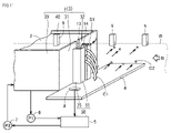
- FIG. 2 is a schematic perspective view showing part of the configuration of the wet processing apparatus 100 according to the first embodiment.
- the wet processing apparatus 100 includes a wet processing tank 1, a pair of rolls 10, a pair of processing liquid shield materials 20, a bottom plate 4, a control tank 5, a first pump P1, It mainly has a second pump P2 and a conveying clip 9 .
- the wet processing bath 1 may be any one of the first processing bath 91 to the sixth processing bath 96 .
- the wet treatment tank 1 may be, for example, a washing treatment tank, an acid washing treatment tank, or a degreasing treatment tank.
- the wet processing tank 1 is, for example, the fourth processing tank 94 .
- the wet processing bath 1 is, for example, a plating bath.
- a wet processing bath 1 contains a processing solution 2 .
- the treatment liquid 2 is, for example, a plating liquid.
- the wet processing tank 1 is provided with a first slit S1 through which the workpiece W passes.
- the first slit S ⁇ b>1 is provided in the side surface portion 3 .
- the side portion 3 includes a first side portion 31 and a second side portion 32 with the first slit S1 interposed therebetween.
- Part of the treatment liquid 2 leaks out from the first slit S1.
- the liquid C1 leaked from the first slit S1 of the wet processing bath 1 passes through the drain hole 8 provided in the bottom plate 4 and enters the control bath 5 .
- the first pump P1 is provided between the wet processing tank 1 and the control tank 5 .
- the first pump P1 returns the processing liquid 2 in the wet processing bath 1 to the control bath 5. As shown in FIG.
- a second pump P2 is provided between the wet processing tank 1 and the control tank 5 .
- the second pump P2 sends the processing liquid 2 processed in the control bath 5 to the wet processing bath 1. As shown in FIG. As described above, the processing liquid 2 circulates between the wet processing bath 1 and the control bath 5 .
- the transport clip 9 transports the work W while gripping it.
- the transport clip 9 moves from the upstream side to the downstream side. Thereby, the work W is conveyed from the upstream side to the downstream side.
- the transport clip 9 grips the work W so as to sandwich the upper end of the work W from both sides, for example.
- a plurality of transport clips 9 are provided along the movement direction B of the workpiece W. As shown in FIG.
- a pair of rolls 10 are positioned outside the wet treatment tank 1 .
- a pair of rolls 10 are attached to the bottom plate 4, for example.
- a pair of rolls 10 are separated from the first slit S1.
- a pair of rolls 10 has a first roll 11 and a second roll 12 . Each of the first roll 11 and the second roll 12 is separated from the first slit S1.
- a pair of rolls 10 are arranged so as to sandwich the work W from the lateral direction.
- a gap is provided between the first roll 11 and the second roll 12 so that the work W can pass between the first roll 11 and the second roll 12 .
- the pair of rolls 10 causes the liquid C1 leaked from the slit S1 to flow out in a direction substantially perpendicular to the moving direction B of the work W. As shown in FIG. This prevents the leaked liquid C1 from adhering to the workpiece W.
- the pair of processing liquid shield materials 20 are located on the opposite side of the pair of rolls 10 from the first slit S1 in the movement direction B of the work W. From another point of view, the pair of processing liquid shielding members 20 is arranged such that the pair of rolls 10 is arranged between the wet processing bath 1 and the pair of processing liquid shielding members 20 in the movement direction B of the work W. . The pair of processing liquid shield materials 20 are arranged so as to sandwich the work W from the lateral direction.
- the pair of treatment liquid shielding materials 20 has a first shielding material 21 and a second shielding material 22 . A gap is provided between the first shield material 21 and the second shield material 22 so that the workpiece W can pass between the first shield material 21 and the second shield material 22 .
- the pair of processing liquid shield materials 20 may be plate-shaped.
- the liquid C1 leaking from the slit S1 in a direction substantially perpendicular to the movement direction B of the work W hits the bottom plate 4 and bounces off to generate splashes.
- the pair of processing liquid shielding members 20 can prevent droplets from adhering to the work W before it is introduced into the wet processing tank 1 .
- FIG. 3 is a schematic top view showing part of the configuration of the wet processing apparatus 100 according to the first embodiment.
- the pair of rolls 10 and the pair of processing liquid shield materials 20 may be positioned upstream in the moving direction B of the work W with respect to the wet processing bath 1 .
- the first roll 11 is positioned between the first shield material 21 and the first side surface portion 31 .
- the second roll 12 is positioned between the second shield material 22 and the second side surface portion 32 .
- the pair of rolls 10 and the pair of processing liquid shield materials 20 are positioned, for example, in the gap between the third processing tank 93 and the fourth processing tank 94 (see FIG. 1).
- the first roll 11 rotates around the first rotation axis A1.
- the second roll 12 rotates around the second rotation axis A2.
- the work W contacts each of the first roll 11 and the second roll 12 .
- each of the first roll 11 and the second roll 12 rotates.
- Each of the first roll 11 and the second roll 12 is, for example, a draining roll. From another point of view, each of the first roll 11 and the second roll 12 removes part of the treatment liquid 2 adhering to the work W.
- a plane containing the first rotation axis A1 and the second rotation axis A2 may be perpendicular to the movement direction B of the workpiece W.
- the wet processing tank 1 includes a pair of side portions 3 (including a ninth side portion 39 and a tenth side portion 40) extending in a direction parallel to the movement direction B of the work W, and a work W movement direction B
- the upstream side surface portion 3 (the first side surface portion 31 and the second side surface portion 32), the downstream side surface portion 3 (the seventh side surface portion 37 and the eighth side surface portion 38) extending in a direction perpendicular to the ).
- the shape of the wet processing tank 1 may be substantially rectangular.
- a first slit S ⁇ b>1 is provided along the height direction of the wet processing tank 1 in the side surface portion 3 on the upstream side.
- a third slit S ⁇ b>3 is provided along the height direction of the wet processing bath 1 in the downstream side portion 3 .
- the work W enters the wet processing tank 1 through the first slit S1.
- the work W exits from the inside of the wet processing tank 1 to the outside through the third slit S3.
- the width of the first slit S1 in top view is not particularly limited, but is, for example, 5 mm.
- the width (first width W1) of the first roll 11 in the direction parallel to the width of the first slit S1 is not particularly limited, but is, for example, 32 mm.
- the width (third width W3) of the first shield material 21 is greater than the width (first width W1) of the first roll 11 in the direction parallel to the width of the first slit S1.
- the width (second width W2) of the second roll 12 in the direction parallel to the width of the first slit S1 is not particularly limited, but is, for example, 32 mm.
- the width of the second shield material 22 (fourth width W4) is greater than the width of the second roll 12 (second width W2) in the direction parallel to the width of the first slit S1.
- the distance between the first side portion 31 and the second side portion 32 and each of the pair of rolls 10 in the moving direction B of the work W may be larger than the width of the slit S1.
- the distance (first distance D1) between the first side surface portion 31 and the first roll 11 in the movement direction B of the work W is larger than the width (fifth width W5) of the first slit S1.
- the distance (second distance D2) between the second side surface portion 32 and the second roll 12 in the moving direction B of the work W is larger than the width (fifth width W5) of the first slit S1.
- each of the first distance D1 and the second distance D2 is not particularly limited, it is, for example, 12 mm.
- Each of the first distance D1 and the second distance D2 may be, for example, 1.5 to 4 times the fifth width W5.
- the first roll 11 is arranged facing the first shield material 21 .
- the first shield material 21 is arranged on the upstream side in the moving direction B of the work W with respect to the first roll 11 .
- the first shield material 21 is arranged as close to the first roll 11 as possible.
- a distance (a third distance D3) between the first roll 11 and the first shield material 21 in the moving direction B of the work W may be smaller than the first distance D1.
- the second roll 12 is arranged facing the second shield material 22 .
- the second shield material 22 is arranged on the upstream side in the movement direction B of the work W with respect to the second roll 12 .
- the second shield material 22 is arranged as close to the second roll 12 as possible.
- the distance (fourth distance D4) between the second roll 12 and the second shield material 22 in the movement direction B of the work W may be smaller than the second distance D2.
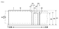
- FIG. 4 is a schematic side view showing the configuration of part of the wet processing apparatus 100 according to the first embodiment.
- the height (first height H1) of the slit S1 is not particularly limited, but may be greater than the height (second height H2) of each of the pair of rolls 10, for example.
- the height (third height H3) of each of the pair of treatment liquid shield materials 20 is not particularly limited, but may be greater than the height (second height H2) of each of the pair of rolls 10, for example.
- the height (third height H3) of each of the pair of treatment liquid shield materials 20 is not particularly limited, but may be smaller than the height (first height H1) of the slit S1, for example.
- the height of the slit is the length of the slit in the height direction.
- the roll height is the axial length of the roll.
- the height of each of the pair of processing liquid shielding materials 20 is the length of each of the pair of processing liquid shielding materials 20 in the height direction.
- the pair of rolls 10 and the pair of processing liquid shield materials 20 are positioned upstream of the wet processing tank 1 in the moving direction of the work W. As shown in FIG. According to this embodiment, the amount of the processing liquid 2 attached to the workpiece W upstream of the pair of processing liquid shield members 20 can be suppressed.
- the pair of rolls 10 and the pair of processing liquid shield materials 20 may be positioned downstream of the wet processing tank 1 in the moving direction of the work W. According to this embodiment, the amount of the processing liquid 2 attached to the work W downstream of the pair of processing liquid shield members 20 can be reduced.
- the wet processing apparatus 100 according to the second embodiment is different from the wet processing apparatus 100 according to the first embodiment in that it mainly includes a third roll 13, a fourth roll 14, and an auxiliary chamber 30.
- Other configurations are the same as those of the wet processing apparatus 100 according to the first embodiment.
- the following description focuses on the configuration different from that of the wet processing apparatus 100 according to the first embodiment.
- FIG. 5 is a schematic perspective view showing the configuration of part of the wet processing apparatus 100 according to the second embodiment.
- the wet processing bath 1 of the wet processing apparatus 100 according to the second embodiment has an auxiliary chamber 30.
- the wet processing apparatus 100 has a third roll 13 and a fourth roll 14 .
- Each of the third roll 13 and the fourth roll 14 is arranged inside the auxiliary chamber 30 .
- FIG. 6 is a schematic top view showing the configuration of part of the wet processing apparatus 100 according to the second embodiment.
- the auxiliary chamber 30 is attached to the side surface 3 on the upstream side.
- the auxiliary chamber 30 is arranged between the side portion 3 on the upstream side and the pair of rolls 10 .
- the auxiliary chamber 30 has an auxiliary chamber side 50 , and the auxiliary chamber side 50 has a fifth side 35 attached to the first side 31 .
- the auxiliary chamber side 50 further includes a sixth side 36 attached to the second side 32 .
- the fifth side portion 35 and the sixth side portion 36 extend in a direction substantially parallel to the moving direction B of the workpiece W. As shown in FIG.
- the side part 50 of the auxiliary chamber further has a third side part 33 , and the third side part 33 is attached to the fifth side part 35 .
- the auxiliary chamber side 50 further has a fourth side 34 attached to the sixth side 36 .
- the third side portion 33 and the fourth side portion 34 extend in a direction substantially perpendicular to the moving direction B of the workpiece W.
- a second slit S ⁇ b>2 is provided along the height direction of the wet processing apparatus 100 between the third side portion 33 and the fourth side portion 34 .
- a first slit S ⁇ b>1 is provided between the first side portion 31 and the second side portion 32 .
- the workpiece W passes through each of the second slit S2, the first slit S1 and the third slit S3 in order.
- the second slit S2, the first slit S1, and the third slit S3 are arranged on a straight line.
- each of the third roll 13 and the fourth roll 14 has a gap between the first side portion 31 and the third side portion 33, and between the second side portion 32 and the fourth side portion 34. located in between.
- Each of the third roll 13 and the fourth roll 14 is provided between the fifth side portion 35 and the sixth side portion 36 in the direction perpendicular to the movement direction B of the work W.
- the third roll 13 rotates around the third rotation axis A3.
- the fourth roll 14 rotates around the fourth rotation axis A4.
- the work W contacts each of the third roll 13 and the fourth roll 14 . As the work W passes between the third roll 13 and the fourth roll 14, each of the third roll 13 and the fourth roll 14 rotates.
- a plane containing the third rotation axis A3 and the fourth rotation axis A4 may be perpendicular to the movement direction B of the workpiece W.
- a plane containing the third axis of rotation A3 and the fourth axis of rotation A4 is substantially parallel to a plane containing the first axis of rotation A1 and the second axis of rotation A2.
- the auxiliary chamber 30 is located on the most upstream side of the wet processing bath 1.
- the processing liquid 2 stored in the wet processing bath 1 is discharged to the outside of the wet processing bath 1 through a second slit S2 formed in the auxiliary chamber 30 .
- the second slit S2 is a slit through which the processing liquid 2 is discharged to the outside of the wet processing tank 1.
- the second slit S2 is positioned on the most upstream side of the wet processing bath 1 .
- the second slit S2 is sandwiched between the third side portion 33 and the fourth side portion 34 .
- the third side portion 33 is positioned between the third roll 13 and the first roll 11 .
- the fourth side portion 34 is positioned between the fourth roll 14 and the second roll 12 .
- the width of the second slit S2 (fifth width W5) in top view is not particularly limited, but is, for example, 5 mm.
- the width (first width W1) of the first roll 11 in the direction parallel to the width of the second slit S2 is not particularly limited, but is, for example, 32 mm.
- the width of the first shield material 21 (third width W3) is greater than the width of the first roll 11 (first width W1) in the direction parallel to the width of the second slit S2.
- the width (second width W2) of the second roll 12 in the direction parallel to the width of the second slit S2 is not particularly limited, but is, for example, 32 mm.
- the width of the second shield material 22 (fourth width W4) is greater than the width of the second roll 12 (second width W2) in the direction parallel to the width of the second slit S2.
- the distance between the first side surface portion 31 and the second side surface portion 32 and each of the pair of rolls 10 in the movement direction B of the work W may be larger than the width of the second slit S2.
- the distance (first distance D1) between the third side portion 33 and the first roll 11 in the moving direction B of the work W is larger than the width (fifth width W5) of the second slit S2.
- the distance (second distance D2) between the fourth side surface portion 34 and the second roll 12 in the movement direction B of the work W is larger than the width (fifth width W5) of the second slit S2.
- each of the first distance D1 and the second distance D2 is not particularly limited, it is, for example, 12 mm.
- Each of the first distance D1 and the second distance D2 may be, for example, 1.5 to 4 times the fifth width W5.
- FIG. 7 is a schematic side view showing the configuration of a wet processing apparatus 100 according to the second embodiment.
- the height of the second slit S2 (first height H1) is not particularly limited. ) may be the same as
- the height (third height H3) of each of the pair of treatment liquid shield materials 20 is not particularly limited, but is greater than the height (fourth height H4) of each of the third roll 13 and the fourth roll 14, for example.
- the height of each of the first roll 11 and the second roll 12 (second height H2) is not particularly limited, but for example the height of each of the third roll 13 and the fourth roll 14 (fourth height H4) may be the same as
- the height of the slit is the length of the slit in the height direction.
- the roll height is the axial length of the roll.
- the height of each of the pair of processing liquid shielding materials 20 is the length of each of the pair of processing liquid shielding materials 20 in the height direction. According to this embodiment, the amount of the processing liquid 2 attached to the workpiece W upstream of the pair of processing liquid shield members 20 can be suppressed.
- the height of each of the first roll 11 and the second roll 12 (second height H2) is at least the same as the height of the second slit S2 (first height H1) or the height of the second slit S2 (first height H1). According to this embodiment, it is possible to suppress the amount of the processing liquid 2 adhering across the width of the workpiece W upstream of the pair of processing liquid shield members 20 .
- the wet processing apparatus 100 according to the third embodiment mainly differs from the wet processing apparatus 100 according to the second embodiment in that a pair of processing liquid shield members 20 are arranged downstream of the wet processing tank 1. , and other configurations are the same as those of the wet processing apparatus 100 according to the second embodiment.
- the following description focuses on the configuration different from that of the wet processing apparatus 100 according to the second embodiment.
- FIG. 8 is a schematic top view showing the configuration of part of the wet processing apparatus 100 according to the third embodiment.
- the pair of processing liquid shield members 20 are arranged downstream of the wet processing tank 1 .
- a pair of rolls 10 are arranged downstream of the wet treatment bath 1 .
- the auxiliary chamber 30 is attached to the downstream side portion 3 (the seventh side portion 37 and the eighth side portion 38).
- the auxiliary chamber 30 is positioned on the most downstream side of the wet processing bath 1 .
- a pair of rolls 10 and a pair of processing liquid shielding materials 20 are provided, for example, in a gap between the fourth processing tank 94 and the fifth processing tank 95 .
- the pair of processing liquid shield materials 20 are arranged downstream of the pair of rolls 10 .
- the first shield material 21 is arranged downstream of the first roll 11 .
- the second shield material 22 is arranged downstream of the second roll 12 .
- the first roll 11 is arranged downstream of the third roll 13 .
- the second roll 12 is arranged downstream of the fourth roll 14 . According to this embodiment, the amount of the processing liquid 2 attached to the work W downstream of the pair of processing liquid shield members 20 can be reduced.
- a second slit S2 is provided along the height direction of the wet processing apparatus 100 between the third side portion 33 and the fourth side portion 34 of the auxiliary chamber 30 .
- the second slit S2 is located on the most downstream side of the wet processing bath 1 .
- a third slit S3 is provided in the side surface portion 3 on the downstream side.
- a first slit S1 is provided in the side surface portion 3 on the upstream side. The work W passes through each of the first slit S1, the third slit S3 and the second slit S2 in order.
- each of the first roll 11 and the second roll 12 is at least the same as the height of the second slit S2 (first height H1) or greater than the height of the second slit S2 (first height H1) . According to this embodiment, it is possible to suppress the amount of the processing liquid 2 attached across the width of the workpiece W downstream of the pair of processing liquid shield members 20 .
- the wet processing apparatus 100 according to the fourth embodiment mainly differs from the wet processing apparatus 100 according to the first embodiment in that the height of each of the pair of rolls 10 is greater than the height of the slit S1, Other configurations are the same as those of the wet processing apparatus 100 according to the first embodiment.
- the following description focuses on the configuration different from that of the wet processing apparatus 100 according to the first embodiment.
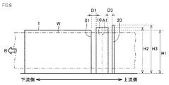
- FIG. 9 is a schematic side view showing the configuration of a wet processing apparatus 100 according to the fourth embodiment.
- the height (second height H2) of each of the pair of rolls 10 may be, for example, greater than the height (first height H1) of the slit S1.
- the height of the first roll 11 is greater than the height of the slit S1.
- the height of the second roll 12 is greater than the height of the slit S1.
- the height (third height H3) of each of the pair of treatment liquid shield materials 20 may be, for example, greater than the height (first height H1) of the slit S1.
- the height of the first shield material 21 may be, for example, greater than the height of the slit S1.
- the height of the second shield material 22 may be greater than the height of the slit S1, for example.
- the height of the slit is the length of the slit in the height direction.
- the roll height is the axial length of the roll.
- the height of the first shield material 21 and the second shield material 22 is the length of the shield material in the height direction. According to this embodiment, it is possible to suppress the amount of the processing liquid 2 adhering across the width of the workpiece W upstream of the pair of processing liquid shield members 20 .
- FIG. 10 is a flow diagram that schematically illustrates a method for manufacturing a flexible printed circuit board 200 according to the present disclosure.
- the method for manufacturing flexible printed circuit board 200 includes a step of preparing a wet processing apparatus having wet processing bath 1 (S10) and a step of processing a workpiece in wet processing bath 1 (S20). mainly have
- a step (S10) of preparing a wet processing apparatus having a wet processing tank 1 is performed.
- the wet processing apparatus 100 according to any one of the first to fourth embodiments is prepared.
- the wet processing apparatus 100 includes an unloading section 101, a winding section 102, a first processing tank 91, a second processing tank 92, a third processing tank 93, and a fourth processing tank. 94 , a fifth processing tank 95 and a sixth processing tank 96 .
- the unloading unit 101 is a machine that unloads the workpiece W before processing.
- a pre-processed work W is wound around the unloading section 101 in a roller shape.
- the work W is, for example, a long sheet-like base material for a flexible printed circuit board.
- Flexible printed circuit board 200 is obtained by a manufacturing method including a step of preparing a wet processing apparatus having wet processing tank 1 (S10) and a step of processing a workpiece in wet processing tank 1 (S20).
- FIG. 12 is a schematic cross-sectional view showing the configuration of the flexible printed circuit board 200.
- flexible printed circuit board 200 has, for example, base material 201 and conductive circuit layer 202 .
- Conductive circuit layers 202 are provided on both sides of the base material 201 .
- Base material 201 is, for example, a polyimide base material.
- Conductive circuit layer 202 is, for example, a copper layer.
- the work W is sent out from the carry-out section 101 .
- the work W sent out from the unloading section 101 passes through the first processing tank 91, the second processing tank 92, and the third processing tank 93 in order.
- the workpiece W is degreased.
- the work W is subjected to a water cleaning process.
- the work W is subjected to an acid cleaning process.
- the work W is electroplated in the fourth treatment tank 94 .
- the work W passes between the pair of treatment liquid shield materials 20 and then between the pair of rolls 10 .
- the work W passes through the first slit S1 provided in the wet processing bath 1 (fourth processing bath 94) and enters the wet processing bath 1.
- a workpiece W is treated with a treatment liquid 2 in a wet treatment tank 1 .
- the work W is plated with the plating solution in the wet treatment tank 1 .
- the work W passes through the second slit S2 provided in the wet processing bath 1 and exits the wet processing bath 1 .
- the work W is transported to the fifth processing bath 95 .
- the work W is subjected to water cleaning treatment.
- the work W is transferred to the sixth processing tank 96 .
- the work W is subjected to a drying process. After the drying treatment in the sixth treatment tank 96 is completed, the work W is collected by the winding section 102 . As described above, the flexible printed circuit board 200 is manufactured.
- the wet treatment tank 1 may be an etching treatment tank, an acid cleaning treatment tank, a degreasing treatment tank, or the like.
- each embodiment may be combined with each other within a non-contradictory range.
- the pair of rolls 10 and the pair of processing liquid shield materials 20 may be provided both upstream and downstream of the wet processing tank 1 .
- FIG. 11 is a schematic perspective view showing the configuration of a wet processing apparatus 100 according to a comparative example.
- the liquid C1 leaking from the slit S1 of the wet processing tank 1 flows out in a direction substantially parallel to the moving direction B of the workpiece W.
- the leaked liquid C1 falls on the bottom plate 4, it hits the bottom plate 4 and rebounds, and droplets C2 of the leaked liquid C1 adhere to the workpiece W. - ⁇ As a result, the quality of the work W may deteriorate.
- the wet processing apparatus 100 includes a pair of rolls 10 outside the first slit S1 or the second slit S2 of the wet processing tank 1.
- the pair of rolls 10 causes the liquid C1 leaked from the first slit S1 or the second slit S2 to flow in a direction substantially perpendicular to the movement direction B of the work W. As shown in FIG. This prevents the leaked liquid C1 from adhering to the workpiece W. As shown in FIG.
- the wet processing apparatus 100 is positioned on the opposite side of the slit S1 with respect to the pair of rolls 10 in the moving direction B of the work W, and is arranged so that the work W passes between them.
- a pair of processing liquid shield members 20 are also included. This prevents the liquid C1 leaking from the slit S1 from hitting and rebounding from the bottom plate 4 and causing splashes C2 to adhere to the work W outside the processing liquid shield material 20 (on the side opposite to the wet processing tank 1). can be suppressed (see FIG. 2). As a result, deterioration of the quality of the work W can be suppressed.
- the distance between the first side surface portion 31, the second side surface portion 32, and the pair of rolls 10 in the moving direction B of the work W is may be larger than the width of the first slit S1 (first embodiment).
- the distance between the third side portion 33, the fourth side portion 34, and each of the pair of rolls 10 in the moving direction B of the work W may be larger than the width of the second slit S2 (second embodiment form).
- the height of each of the pair of rolls 10 is the same as the height of the first slit S1 or the second slit S2, or It may be equal to or higher than the height of S1 or the second slit S2. As a result, it is possible to suppress the treatment liquid 2 from leaking over the pair of rolls 10 from the upper side of the first slit S1 or the second slit S2 and adhering to the workpiece W.
- the wet processing bath 1 may be a plating processing bath.
- the treatment liquid 2 is a plating liquid.
- Oxygen dissolves into the plating solution from the atmosphere on the surface where the plating solution is exposed to the air.
- the oxygen acts as an oxidizing agent and oxidizes the thin film circuit of the workpiece W.
- oxygen is supplied from the atmosphere to the adherent solution, resulting in a rapid increase in the oxygen concentration of the adherent solution. Therefore, the thin-film circuit of the workpiece W is likely to corrode.
- thin film circuits used in the semi-additive process are more likely to cause conduction failures due to corrosion.
- the pair of rolls 10 and the pair of processing liquid shield materials 20 in the wet processing apparatus 100, corrosion of the thin film circuit of the work W can be suppressed. Even if the treatment liquid 2 is water, oxygen dissolved in the water acts as an oxidizing agent.
- the pair of rolls 10 and the pair of processing liquid shield materials 20 are arranged upstream of the wet processing bath 1 in the moving direction B of the work W. may be located on the side.
- the work W on the downstream side of the wet treatment tank 1 has already been plated. Therefore, the work W on the downstream side of the wet processing tank 1 is less likely to corrode than the work W on the upstream side of the wet processing tank 1 .
- the flexible printed circuit boards 200 according to samples 3 and 4 were manufactured using an apparatus obtained by removing the pair of rollers and the pair of processing liquid shield materials 20 from the wet processing apparatus 100 according to the second embodiment (see FIG. 11).
- the line speed (moving speed of the workpiece W) was 0.1 m/min and 0.5 m/min, respectively.
- the work W was a long sheet-like base material.
- the width of the substrate was 250 mm.
- a polyimide base material was used as the base material.
- the thickness of the base material was 25 ⁇ m.
- a daisy chain circuit pattern was formed on both sides of the substrate.
- the circuit pattern was made of copper.
- the thickness of the circuit was set to 0.4 ⁇ m.
- the width of the circuit was 0.5 mm.
- the length of the circuit was 3.0 mm.
- the pitch in the width direction of the circuits was set to 2.0 mm.
- the length direction pitch of the circuit was set to 5.0 mm.
- the plating solution was copper sulfate.
- the temperature of the plating solution was 25°C.
- Polyolefin was used as the material for each of the first roll 11 and the second roll 12 .
- Each diameter of the first roll 11 and the second roll 12 was 32 mm.
- the material of each of the first shield material 21 and the second shield material 22 was PVC (polyvinyl chloride).
- Each thickness of the first shield material 21 and the second shield material 22 was set to 3 mm.
- Each of the first distance D1 and the second distance D2 was set to 12 mm.
- Each of the third distance D3 and the fourth distance D4 was set to 0 mm.
- the second height H2 was set to 300 mm.
- the number of defective (disconnected) locations in the daisy chain circuit patterns provided on both sides of the base material was measured.
- the total number of circuits is 10000.
- the defect rate is the ratio of the number of defective circuits to the total number of circuits.
- the defective rate of each of the flexible printed circuit boards 200 according to samples 1 and 2 was 0%.
- the defective rates of the flexible printed circuit boards 200 according to samples 3 and 4 were 0.67% and 0.02%, respectively. From the above results, by installing a pair of processing liquid shielding materials 20 in the wet processing apparatus 100, it is possible to suppress adhesion of droplets of the processing liquid 2 to the work W and reduce the defective rate of the flexible printed circuit board 200. One thing was confirmed.
- Reference Signs List 1 wet processing tank 2 processing liquid 3 side surface 4 bottom plate 5 control tank 8 drainage hole 9 transport clip 10 pair of rolls 11 first roll 12 second roll 13 third roll 14 fourth roll 20 pair of processing liquid shield materials 21 First shield material 22 Second shield material 30 Auxiliary chamber 31 First side surface 32 Second side surface 33 Third side surface 34 Fourth side surface 35 Fifth side surface 36 Sixth side surface 37 Seventh side surface 38 Eighth side surface Side portion 39 Ninth side portion 40 Tenth side portion 50 Side portion of auxiliary chamber 91 First treatment tank 92 Second treatment tank 93 Third treatment tank 94 Fourth treatment tank 95 Fifth treatment tank 96 Sixth treatment tank 100 Wet Processing device 101 Unloading unit 102 Winding unit 200 Flexible printed circuit board 201 Base material 202 Conductive circuit layer A1 First rotation axis A2 Second rotation axis A3 Third rotation axis A4 Fourth rotation axis B Movement direction C1 Liquid C2 Droplets D1 First Distance D2 Second distance D3 Third distance D4 Fourth distance H1 First height (height of first slit S1 or second slit S
Abstract
Description
従来の連続湿式処理装置においては、処理槽から漏れ出た処理液がワークに付着することで、ワークの品質が劣化することがあった。
本開示によれば、ワークの品質が劣化することを抑制可能な湿式処理装置およびフレキシブルプリント基板の製造方法を提供することができる。
まず本開示の実施形態の概要について説明する。
以下、本開示の実施形態の詳細について説明する。以下の説明では、同一または対応する要素には同一の符号を付し、それらについて同じ説明は繰り返さない。
(第1実施形態)
まず、本開示の第1実施形態に係る湿式処理装置100の構成について説明する。図1は、第1実施形態に係る湿式処理装置100の全体構成を示す斜視模式図である。第1実施形態に係る湿式処理装置100は、連続的に移動するワークWを処理する湿式処理装置100である。図1に示されるように、湿式処理装置100は、搬出部101と、巻取部102と、第1処理槽91と、第2処理槽92と、第3処理槽93と、第4処理槽94と、第5処理槽95と、第6処理槽96とを主に有している。搬出部101は、処理前のワークWを送り出す機械である。搬出部101には、処理前のワークWがローラ状に巻かれている。巻取部102は、処理後のワークWを回収する機械である。巻取部102には、処理後のワークWがローラ状に巻かれている。ワークWの種類は、特に限定されないが、長尺シート状部材であり、たとえばポリイミド基材上に薄膜回路が形成されたフレキシブルプリント基板である。ワークWの移動方向とワークWの長手方向が略同じであり、長手方向に垂直な方向がワークWの幅方向である。ワークWの幅方向は湿式処理装置100の高さ方向と略同じである。
上面視において、湿式処理槽1の形状は、略長方形であってもよい。上流側の側面部3には、湿式処理槽1の高さ方向に沿って第1スリットS1が設けられている。下流側の側面部3には、湿式処理槽1の高さ方向に沿って第3スリットS3が設けられている。ワークWは、第1スリットS1を通って湿式処理槽1の内部に入る。ワークWは、第3スリットS3を通って湿式処理槽1の内部から外部に出る。
実施形態1では、一対のロール10および一対の処理液シールド材20は、湿式処理槽1に対してワークWの移動方向の上流側に位置している。この形態によると、一対の処理液シールド材20より上流側にあるワークWに対する処理液2の付着量を抑えることができる。或いは、一対のロール10および一対の処理液シールド材20は、湿式処理槽1に対してワークWの移動方向の下流側に位置してもよい。この形態によると、一対の処理液シールド材20より下流側にあるワークWに対する処理液2の付着量を抑えることができる。
次に、本開示の第2実施形態に係る湿式処理装置100の構成について説明する。第2実施形態に係る湿式処理装置100は、主に、第3ロール13と第4ロール14と補助室30とを有している点において、第1実施形態に係る湿式処理装置100と異なっており、その他の構成については、第1実施形態に係る湿式処理装置100と同様である。以下、第1実施形態に係る湿式処理装置100と異なる構成を中心に説明する。
補助室30は、上流側の側面部3と一対のロール10との間に配置されている。補助室30は補助室の側面部50を有し、補助室の側面部50は、第5側面部35を有し、第5側面部35は第1側面部31に取り付けられている。補助室の側面部50は、さらに第6側面部36を有し、第6側面部36は第2側面部32に取り付けられている。第5側面部35と第6側面部36は、ワークWの移動方向Bとほぼ平行な方向に延在している。
この形態によると、一対の処理液シールド材20より上流側にあるワークWに対する処理液2の付着量を抑えることができる。
或いは、第1ロール11及び第2ロール12の各々の高さ(第2高さH2)は、少なくとも第2スリットS2の高さ(第1高さH1)と同じ又は第2スリットS2の高さ(第1高さH1)より大きい。この形態によると、一対の処理液シールド材20より上流側にあるワークWの幅方向にわたって処理液2の付着量を抑えることができる。
次に、本開示の第3実施形態に係る湿式処理装置100の構成について説明する。第3実施形態に係る湿式処理装置100は、主に、一対の処理液シールド材20が湿式処理槽1の下流側に配置されている点において、第2実施形態に係る湿式処理装置100と異なっており、その他の構成については、第2実施形態に係る湿式処理装置100と同様である。以下、第2実施形態に係る湿式処理装置100と異なる構成を中心に説明する。
この形態によると、一対の処理液シールド材20より下流側にあるワークWに対する処理液2の付着量を抑えることができる。
次に、本開示の第4実施形態に係る湿式処理装置100の構成について説明する。第4実施形態に係る湿式処理装置100は、主に、一対のロール10の各々の高さがスリットS1の高さよりも大きい点において、第1実施形態に係る湿式処理装置100と異なっており、その他の構成については、第1実施形態に係る湿式処理装置100と同様である。
以下、第1実施形態に係る湿式処理装置100と異なる構成を中心に説明する。
この形態によると、一対の処理液シールド材20より上流側にあるワークWの幅方向にわたって処理液2の付着量を抑えることができる。
次に、本開示に係るフレキシブルプリント基板200の製造方法について説明する。図10は、本開示に係るフレキシブルプリント基板200の製造方法を概略的に説明するフロー図である。図10に示されるように、フレキシブルプリント基板200の製造方法は、湿式処理槽1を有する湿式処理装置を準備する工程(S10)と、湿式処理槽1においてワークを処理する工程(S20)とを主に有している。
第2処理槽92においては、ワークWに対して水洗浄処理が実施される。第3処理槽93においては、ワークWに対して酸洗浄処理が実施される。
第6処理槽96においては、ワークWに対して乾燥処理が実施される。第6処理槽96における乾燥処理が終了した後、ワークWは巻取部102によって回収される。以上により、フレキシブルプリント基板200が製造される。
さらに、実施形態に係る湿式処理装置100は、ワークWの移動方向Bにおいて、一対のロール10に対してスリットS1の反対側に位置し、かつワークWがこれらの間を通過するように配置された一対の処理液シールド材20を含んでいる。これにより、スリットS1から漏れ出た液C1が、底板4にあたって跳ね返って生じた飛沫C2が、処理液シールド材20の外側の(湿式処理槽1とは反対側の)ワークWに付着することを抑制することができる(図2参照)。結果として、ワークWの品質が劣化することを抑制することができる。
まず、サンプル1~4に係るフレキシブルプリント基板200を準備した。サンプル1および2に係るフレキシブルプリント基板200は、第2実施形態に係る湿式処理装置100を使用して製造した(図5参照)。サンプル1および2に係るフレキシブルプリント基板200の製造方法において、ラインスピード(ワークWの移動速度)は、それぞれ0.1m/分および0.5m/分とした。
ワークWは、長尺シート状の基材とした。基材の幅は、250mmとした。基材は、ポリイミド基材とした。基材の厚みは、25μmとした。基材の両面にデージーチェーン回路パターンを形成した。回路パターンは、銅とした。回路の厚みは、0.4μmとした。回路の幅は、0.5mmとした。回路の長さは、3.0mmとした。回路の幅方向ピッチは、2.0mmとした。回路の長さ方向ピッチは、5.0mmとした。

2 処理液
3 側面部
4 底板
5 管理槽
8 排液孔
9 搬送クリップ
10 一対のロール
11 第1ロール
12 第2ロール
13 第3ロール
14 第4ロール
20 一対の処理液シールド材
21 第1シールド材
22 第2シールド材
30 補助室
31 第1側面部
32 第2側面部
33 第3側面部
34 第4側面部
35 第5側面部
36 第6側面部
37 第7側面部
38 第8側面部
39 第9側面部
40 第10側面部
50 補助室の側面部
91 第1処理槽
92 第2処理槽
93 第3処理槽
94 第4処理槽
95 第5処理槽
96 第6処理槽
100 湿式処理装置
101 搬出部
102 巻取部
200 フレキシブルプリント基板
201 基材
202 導電回路層
A1 第1回転軸
A2 第2回転軸
A3 第3回転軸
A4 第4回転軸
B 移動方向
C1 液
C2 飛沫
D1 第1距離
D2 第2距離
D3 第3距離
D4 第4距離
H1 第1高さ(第1スリットS1又は第2スリットS2の高さ)
H2 第2高さ
H3 第3高さ
H4 第4高さ
P1 第1ポンプ
P2 第2ポンプ
S1 第1スリット(スリット)
S2 第2スリット
S3 第3スリット
W ワーク
W1 第1幅
W2 第2幅
W3 第3幅
W4 第4幅
W5 第5幅(第1スリットS1又は第2スリットS2の幅)
W6 第6幅
Claims (21)
- 連続的に移動するシート状であるワークを処理する湿式処理装置であって、
前記ワークが通過するように高さ方向に第1スリットが設けられた側面部を有する湿式処理槽と、
前記湿式処理槽の外側に位置し、前記第1スリットから離間し、かつ前記ワークを横方向から挟み込むように配置された一対のロールと、
前記ワークの移動方向において、前記一対のロールに対して前記湿式処理槽の反対側に位置する一対の処理液シールド材とを備え、
前記側面部は、前記第1スリットを挟んで第1側面部と第2側面部とを含み、
前記一対の処理液シールド材は、第1シールド材と第2シールド材とを含み、前記第1シールド材と前記第2シールド材は、前記第1シールド材と前記第2シールド材との間を前記ワークが通過できるように配置されており、
前記一対のロールは、前記第1シールド材と前記第1側面部との間に位置する第1ロールと、前記第2シールド材と前記第2側面部との間に位置する第2ロールとを含み、
前記第1スリットの幅に平行な方向において、前記第1シールド材の幅は前記第1ロールの幅よりも大きく、かつ、前記第2シールド材の幅は前記第2ロールの幅よりも大きい、湿式処理装置。 - 前記ワークの移動方向における前記第1側面部と前記第1ロールの距離と、前記第2側面部と前記第2ロールの距離のそれぞれは、前記第1スリットの幅よりも大きい、請求項1に記載の湿式処理装置。
- 前記第1ロール及び第2ロールの各々の高さは、前記第1スリットの高さと同じ又は前記第1スリットの高さより大きい、請求項1又は請求項2に記載の湿式処理装置。
- 前記一対のロールおよび前記一対の処理液シールド材は、前記湿式処理槽に対して前記ワークの移動方向の上流側に位置している、請求項1から請求項3のいずれか1項に記載の湿式処理装置。
- 連続的に移動するシート状であるワークを処理する湿式処理装置であって、
前記ワークが通過するように高さ方向に第1スリットが設けられた側面部を有する湿式処理槽と、
前記湿式処理槽の外側に位置し、前記ワークを横方向から挟み込むように配置された一対のロールと、
前記ワークの移動方向において、前記一対のロールに対して前記湿式処理槽の反対側に位置する一対の処理液シールド材と、
前記側面部と前記一対のロールとの間に設けられた補助室と、
前記補助室の内部に備わる追加の一対のロールを備え、
前記補助室は、前記ワークが通過するように高さ方向に第2スリットが設けられた補助室の側面部を有し、
前記補助室の側面部は、前記第2スリットを挟んで第3側面部と第4側面部とを含み、
前記一対の処理液シールド材は、第1シールド材と第2シールド材とを含み、前記第1シールド材と前記第2シールド材は、前記第1シールド材と前記第2シールド材との間を前記ワークが通過できるように配置されており、
前記一対のロールは、前記第1シールド材と前記第3側面部との間に位置する第1ロールと、前記第2シールド材と前記第4側面部との間に位置する第2ロールとを含み、
前記第2スリットの幅に平行な方向において、前記第1シールド材の幅は前記第1ロールの幅よりも大きく、かつ、前記第2シールド材の幅は前記第2ロールの幅よりも大きい、湿式処理装置。 - 前記ワークの移動方向における前記第3側面部と前記第1ロールとの距離と、前記第4側面部と前記第2ロールとの距離のそれぞれは、前記第2スリットの幅よりも大きい、請求項5に記載の湿式処理装置。
- 前記第1ロール及び第2ロールの各々の高さは、前記第2スリットの高さと同じ又は前記第2スリットの高さより大きい、請求項5又は請求項6に記載の湿式処理装置。
- 前記一対のロール、前記一対の処理液シールド材、前記補助室および前記追加の一対のロールは、前記湿式処理槽に対して前記ワークの移動方向の上流側に位置している、請求項5から請求項7のいずれか1項に記載の湿式処理装置。
- 前記湿式処理槽は、めっき処理槽である、請求項1から請求項8のいずれか1項に記載の湿式処理装置。
- 前記一対の処理液シールド材が板状である請求項1から請求項9のいずれか1項に記載の湿式処理装置。
- 湿式処理槽を有する湿式処理装置を準備する工程と、
前記湿式処理槽において、シート状であるフレキシブルプリント基板用基材を湿式処理する工程とを備え、
前記湿式処理装置は、
連続的に移動する前記フレキシブルプリント基板用基材を処理する湿式処理装置であって、
前記フレキシブルプリント基板用基材が通過するように高さ方向に第1スリットが設けられた側面部を有する湿式処理槽と、
前記湿式処理槽の外側に位置し、前記第1スリットから離間し、かつ前記フレキシブルプリント基板用基材を横方向から挟み込むように配置された一対のロールと、
前記フレキシブルプリント基板用基材の移動方向において、前記一対のロールに対して前記湿式処理槽の反対側に位置する一対の処理液シールド材とを含み、
前記側面部は、前記第1スリットを挟んで第1側面部と第2側面部とを含み、
前記一対の処理液シールド材は、第1シールド材と第2シールド材とを含み、前記第1シールド材と前記第2シールド材は、前記第1シールド材と前記第2シールド材との間を前記フレキシブルプリント基板用基材が通過できるように配置されており、
前記一対のロールは、前記第1シールド材と前記第1側面部との間に位置する第1ロールと、前記第2シールド材と前記第2側面部との間に位置する第2ロールとを含み、
前記第1スリットの幅に平行な方向において、前記第1シールド材の幅は前記第1ロールの幅よりも大きく、かつ、前記第2シールド材の幅は前記第2ロールの幅よりも大きい、フレキシブルプリント基板の製造方法。 - 前記フレキシブルプリント基板用基材の移動方向における前記第1側面部と前記第1ロールとの距離と、前記第2側面部と前記第2ロールとの距離のそれぞれは、前記第1スリットの幅よりも大きい、請求項11に記載のフレキシブルプリント基板の製造方法。
- 前記第1ロール及び第2ロールの各々の高さは、前記第1スリットの高さと同じ又は前記第1スリットの高さより大きい、請求項11又は請求項12に記載のフレキシブルプリント基板の製造方法。
- 前記一対のロールおよび前記一対の処理液シールド材は、前記湿式処理槽に対して前記フレキシブルプリント基板用基材の移動方向の上流側に位置している、請求項11から請求項13のいずれか1項に記載のフレキシブルプリント基板の製造方法。
- 湿式処理槽を有する湿式処理装置を準備する工程と、
前記湿式処理槽において、シート状であるフレキシブルプリント基板用基材を湿式処理する工程とを備え、
前記湿式処理装置は、
連続的に移動する前記フレキシブルプリント基板用基材を処理する湿式処理装置であって、
前記フレキシブルプリント基板用基材が通過するように高さ方向に第1スリットが設けられた側面部を有する湿式処理槽と、
前記湿式処理槽の外側に位置し、前記フレキシブルプリント基板用基材を横方向から挟み込むように配置された一対のロールと、
前記フレキシブルプリント基板用基材の移動方向において、前記一対のロールに対して前記湿式処理槽の反対側に位置する一対の処理液シールド材と、
前記側面部と前記一対のロールとの間に設けられた補助室と、
前記補助室の内部に備わる追加の一対のロールを含み、
前記補助室は、前記フレキシブルプリント基板用基材が通過するように高さ方向に第2スリットが設けられた補助室の側面部を有し、
前記補助室の側面部は、前記第2スリットを挟んで第3側面部と第4側面部とを含み、
前記一対の処理液シールド材は、第1シールド材と第2シールド材とを含み、前記第1シールド材と前記第2シールド材は、前記第1シールド材と前記第2シールド材との間を前記フレキシブルプリント基板用基材が通過できるように配置されており、
前記一対のロールは、前記第1シールド材と前記第3側面部との間に位置する第1ロールと、前記第2シールド材と前記第4側面部との間に位置する第2ロールとを含み、
前記第2スリットの幅に平行な方向において、前記第1シールド材の幅は前記第1ロールの幅よりも大きく、かつ、前記第2シールド材の幅は前記第2ロールの幅よりも大きい、フレキシブルプリント基板の製造方法。 - 前記フレキシブルプリント基板用基材の移動方向における前記第3側面部と前記第1ロールとの距離と、前記第4側面部と前記第2ロールとの距離のそれぞれは、前記第2スリットの幅よりも大きい、請求項15に記載のフレキシブルプリント基板の製造方法。
- 前記第1ロール及び第2ロールの各々の高さは、前記第2スリットの高さと同じ又は前記第2スリットの高さより大きい、請求項15又は請求項16に記載のフレキシブルプリント基板の製造方法。
- 前記一対のロール、前記一対の処理液シールド材、前記補助室および前記追加の一対のロールは、前記湿式処理槽に対して前記フレキシブルプリント基板用基材の移動方向の上流側に位置している、請求項15から請求項17のいずれか1項に記載のフレキシブルプリント基板の製造方法。
- 前記湿式処理槽は、めっき処理槽である、請求項11から請求項18のいずれか1項に記載のフレキシブルプリント基板の製造方法。
- 前記一対の処理液シールド材が板状である請求項11から請求項19のいずれか1項に記載のフレキシブルプリント基板の製造方法。
- 前記フレキシブルプリント基板用基材の移動速度は、0.1m/分以上0.5m/分以下である請求項11から請求項20のいずれか1項に記載のフレキシブルプリント基板の製造方法。
Priority Applications (2)
| Application Number | Priority Date | Filing Date | Title |
|---|---|---|---|
| CN202280029725.6A CN117178082A (zh) | 2021-04-22 | 2022-04-13 | 湿式处理装置及柔性印刷基板的制造方法 |
| JP2023515431A JPWO2022224886A1 (ja) | 2021-04-22 | 2022-04-13 |
Applications Claiming Priority (2)
| Application Number | Priority Date | Filing Date | Title |
|---|---|---|---|
| JP2021072460 | 2021-04-22 | ||
| JP2021-072460 | 2021-04-22 |
Publications (1)
| Publication Number | Publication Date |
|---|---|
| WO2022224886A1 true WO2022224886A1 (ja) | 2022-10-27 |
Family
ID=83722954
Family Applications (1)
| Application Number | Title | Priority Date | Filing Date |
|---|---|---|---|
| PCT/JP2022/017679 WO2022224886A1 (ja) | 2021-04-22 | 2022-04-13 | 湿式処理装置およびフレキシブルプリント基板の製造方法 |
Country Status (3)
| Country | Link |
|---|---|
| JP (1) | JPWO2022224886A1 (ja) |
| CN (1) | CN117178082A (ja) |
| WO (1) | WO2022224886A1 (ja) |
Citations (2)
| Publication number | Priority date | Publication date | Assignee | Title |
|---|---|---|---|---|
| JPS59181870U (ja) * | 1983-05-18 | 1984-12-04 | 三菱電機株式会社 | 条材の連続電気メツキ装置の回収槽 |
| JP2003147582A (ja) * | 2001-11-09 | 2003-05-21 | Nichiyo Engineering Kk | 連続湿式処理方法及び装置並びに液シール方法及び装置 |
-
2022
- 2022-04-13 JP JP2023515431A patent/JPWO2022224886A1/ja active Pending
- 2022-04-13 CN CN202280029725.6A patent/CN117178082A/zh active Pending
- 2022-04-13 WO PCT/JP2022/017679 patent/WO2022224886A1/ja active Application Filing
Patent Citations (2)
| Publication number | Priority date | Publication date | Assignee | Title |
|---|---|---|---|---|
| JPS59181870U (ja) * | 1983-05-18 | 1984-12-04 | 三菱電機株式会社 | 条材の連続電気メツキ装置の回収槽 |
| JP2003147582A (ja) * | 2001-11-09 | 2003-05-21 | Nichiyo Engineering Kk | 連続湿式処理方法及び装置並びに液シール方法及び装置 |
Also Published As
| Publication number | Publication date |
|---|---|
| JPWO2022224886A1 (ja) | 2022-10-27 |
| CN117178082A (zh) | 2023-12-05 |
Similar Documents
| Publication | Publication Date | Title |
|---|---|---|
| JP4786393B2 (ja) | 洗浄装置及びめっき被膜付きフィルムの製造装置 | |
| JP2007270321A5 (ja) | ||
| JP7107190B2 (ja) | 銅張積層板の製造方法 | |
| JP5673582B2 (ja) | 電気めっきの前処理方法及び該前処理方法を含んだ電気めっき方法による銅張積層樹脂フィルムの製造方法 | |
| KR20100112345A (ko) | 인쇄회로기판의 비접촉 웨트처리 반송방법 | |
| WO2022224886A1 (ja) | 湿式処理装置およびフレキシブルプリント基板の製造方法 | |
| JP6493051B2 (ja) | 長尺導電性基板の電気めっき方法及び電気めっき装置、並びに該電気めっき方法を用いた金属化ポリイミドフィルムの製造方法 | |
| TW200824518A (en) | Conveyer for surface treatment | |
| KR20060106572A (ko) | 필름 연속 도금 장치 및 방법 | |
| JP4652794B2 (ja) | 連続設備で平坦な材料を接触せずに搬送および処理する方法および装置 | |
| JP2006222117A (ja) | 基板材の搬送装置 | |
| JP7215211B2 (ja) | 銅張積層板の製造方法 | |
| JP2009256757A (ja) | フィルム支持装置及びめっき被膜付きフィルムの製造装置 | |
| JP4285018B2 (ja) | ウエット処理装置の液切りと液置換装置 | |
| JP4652793B2 (ja) | 連続設備で平坦な材料を処理する方法および装置 | |
| TWI699833B (zh) | 導體形成裝置及導體製造方法 | |
| TWI615510B (zh) | 吸入鍍覆裝置 | |
| KR102575905B1 (ko) | 도금 장치 | |
| JP6115311B2 (ja) | 表面処理方法およびそれを用いた金属化樹脂フィルムの製造方法 | |
| TWI229048B (en) | Transportation device for substrate materials | |
| JP4805195B2 (ja) | 軸受体、液切り装置及びめっき被膜付きフィルムの製造装置 | |
| JPWO2022224886A5 (ja) | ||
| JP7409150B2 (ja) | 銅張積層板の製造方法 | |
| JP7172334B2 (ja) | イオンビーム処理手段を備えた金属膜付樹脂フィルム基板の製造装置及び製造方法 | |
| JP2008013270A (ja) | 軟性基板材の表面処理装置 |
Legal Events
| Date | Code | Title | Description |
|---|---|---|---|
| 121 | Ep: the epo has been informed by wipo that ep was designated in this application |
Ref document number: 22791660 Country of ref document: EP Kind code of ref document: A1 |
|
| WWE | Wipo information: entry into national phase |
Ref document number: 2023515431 Country of ref document: JP |
|
| WWE | Wipo information: entry into national phase |
Ref document number: 18286999 Country of ref document: US |
|
| NENP | Non-entry into the national phase |
Ref country code: DE |
|
| 122 | Ep: pct application non-entry in european phase |
Ref document number: 22791660 Country of ref document: EP Kind code of ref document: A1 |