WO2022224878A1 - 空気処理装置 - Google Patents
空気処理装置 Download PDFInfo
- Publication number
- WO2022224878A1 WO2022224878A1 PCT/JP2022/017600 JP2022017600W WO2022224878A1 WO 2022224878 A1 WO2022224878 A1 WO 2022224878A1 JP 2022017600 W JP2022017600 W JP 2022017600W WO 2022224878 A1 WO2022224878 A1 WO 2022224878A1
- Authority
- WO
- WIPO (PCT)
- Prior art keywords
- air
- region
- heat exchanger
- fin group
- core
- Prior art date
- Legal status (The legal status is an assumption and is not a legal conclusion. Google has not performed a legal analysis and makes no representation as to the accuracy of the status listed.)
- Ceased
Links
Images



Classifications
-
- F—MECHANICAL ENGINEERING; LIGHTING; HEATING; WEAPONS; BLASTING
- F24—HEATING; RANGES; VENTILATING
- F24F—AIR-CONDITIONING; AIR-HUMIDIFICATION; VENTILATION; USE OF AIR CURRENTS FOR SCREENING
- F24F7/00—Ventilation
- F24F7/007—Ventilation with forced flow
-
- F—MECHANICAL ENGINEERING; LIGHTING; HEATING; WEAPONS; BLASTING
- F24—HEATING; RANGES; VENTILATING
- F24F—AIR-CONDITIONING; AIR-HUMIDIFICATION; VENTILATION; USE OF AIR CURRENTS FOR SCREENING
- F24F12/00—Use of energy recovery systems in air conditioning, ventilation or screening
- F24F12/001—Use of energy recovery systems in air conditioning, ventilation or screening with heat-exchange between supplied and exhausted air
- F24F12/006—Use of energy recovery systems in air conditioning, ventilation or screening with heat-exchange between supplied and exhausted air using an air-to-air heat exchanger
-
- F—MECHANICAL ENGINEERING; LIGHTING; HEATING; WEAPONS; BLASTING
- F24—HEATING; RANGES; VENTILATING
- F24F—AIR-CONDITIONING; AIR-HUMIDIFICATION; VENTILATION; USE OF AIR CURRENTS FOR SCREENING
- F24F13/00—Details common to, or for air-conditioning, air-humidification, ventilation or use of air currents for screening
- F24F13/02—Ducting arrangements
-
- F—MECHANICAL ENGINEERING; LIGHTING; HEATING; WEAPONS; BLASTING
- F24—HEATING; RANGES; VENTILATING
- F24F—AIR-CONDITIONING; AIR-HUMIDIFICATION; VENTILATION; USE OF AIR CURRENTS FOR SCREENING
- F24F13/00—Details common to, or for air-conditioning, air-humidification, ventilation or use of air currents for screening
- F24F13/20—Casings or covers
-
- F—MECHANICAL ENGINEERING; LIGHTING; HEATING; WEAPONS; BLASTING
- F24—HEATING; RANGES; VENTILATING
- F24F—AIR-CONDITIONING; AIR-HUMIDIFICATION; VENTILATION; USE OF AIR CURRENTS FOR SCREENING
- F24F13/00—Details common to, or for air-conditioning, air-humidification, ventilation or use of air currents for screening
- F24F13/30—Arrangement or mounting of heat-exchangers
-
- F—MECHANICAL ENGINEERING; LIGHTING; HEATING; WEAPONS; BLASTING
- F24—HEATING; RANGES; VENTILATING
- F24F—AIR-CONDITIONING; AIR-HUMIDIFICATION; VENTILATION; USE OF AIR CURRENTS FOR SCREENING
- F24F7/00—Ventilation
- F24F7/04—Ventilation with ducting systems, e.g. by double walls; with natural circulation
- F24F7/06—Ventilation with ducting systems, e.g. by double walls; with natural circulation with forced air circulation, e.g. by fan positioning of a ventilator in or against a conduit
- F24F7/08—Ventilation with ducting systems, e.g. by double walls; with natural circulation with forced air circulation, e.g. by fan positioning of a ventilator in or against a conduit with separate ducts for supplied and exhausted air with provisions for reversal of the input and output systems
-
- F—MECHANICAL ENGINEERING; LIGHTING; HEATING; WEAPONS; BLASTING
- F28—HEAT EXCHANGE IN GENERAL
- F28D—HEAT-EXCHANGE APPARATUS, NOT PROVIDED FOR IN ANOTHER SUBCLASS, IN WHICH THE HEAT-EXCHANGE MEDIA DO NOT COME INTO DIRECT CONTACT
- F28D21/00—Heat-exchange apparatus not covered by any of the groups F28D1/00 - F28D20/00
- F28D21/0001—Recuperative heat exchangers
- F28D21/0003—Recuperative heat exchangers the heat being recuperated from exhaust gases
- F28D21/0005—Recuperative heat exchangers the heat being recuperated from exhaust gases for domestic or space-heating systems
- F28D21/0008—Air heaters
-
- F—MECHANICAL ENGINEERING; LIGHTING; HEATING; WEAPONS; BLASTING
- F28—HEAT EXCHANGE IN GENERAL
- F28D—HEAT-EXCHANGE APPARATUS, NOT PROVIDED FOR IN ANOTHER SUBCLASS, IN WHICH THE HEAT-EXCHANGE MEDIA DO NOT COME INTO DIRECT CONTACT
- F28D21/00—Heat-exchange apparatus not covered by any of the groups F28D1/00 - F28D20/00
- F28D21/0015—Heat and mass exchangers, e.g. with permeable walls
-
- F—MECHANICAL ENGINEERING; LIGHTING; HEATING; WEAPONS; BLASTING
- F28—HEAT EXCHANGE IN GENERAL
- F28D—HEAT-EXCHANGE APPARATUS, NOT PROVIDED FOR IN ANOTHER SUBCLASS, IN WHICH THE HEAT-EXCHANGE MEDIA DO NOT COME INTO DIRECT CONTACT
- F28D9/00—Heat-exchange apparatus having stationary plate-like or laminated conduit assemblies for both heat-exchange media, the media being in contact with different sides of a conduit wall
- F28D9/0062—Heat-exchange apparatus having stationary plate-like or laminated conduit assemblies for both heat-exchange media, the media being in contact with different sides of a conduit wall the conduits for one heat-exchange medium being formed by spaced plates with inserted elements
-
- F—MECHANICAL ENGINEERING; LIGHTING; HEATING; WEAPONS; BLASTING
- F28—HEAT EXCHANGE IN GENERAL
- F28F—DETAILS OF HEAT-EXCHANGE AND HEAT-TRANSFER APPARATUS, OF GENERAL APPLICATION
- F28F3/00—Plate-like or laminated elements; Assemblies of plate-like or laminated elements
- F28F3/02—Elements or assemblies thereof with means for increasing heat-transfer area, e.g. with fins, with recesses, with corrugations
- F28F3/025—Elements or assemblies thereof with means for increasing heat-transfer area, e.g. with fins, with recesses, with corrugations the means being corrugated, plate-like elements
-
- F—MECHANICAL ENGINEERING; LIGHTING; HEATING; WEAPONS; BLASTING
- F28—HEAT EXCHANGE IN GENERAL
- F28F—DETAILS OF HEAT-EXCHANGE AND HEAT-TRANSFER APPARATUS, OF GENERAL APPLICATION
- F28F3/00—Plate-like or laminated elements; Assemblies of plate-like or laminated elements
- F28F3/08—Elements constructed for building-up into stacks, e.g. capable of being taken apart for cleaning
-
- Y—GENERAL TAGGING OF NEW TECHNOLOGICAL DEVELOPMENTS; GENERAL TAGGING OF CROSS-SECTIONAL TECHNOLOGIES SPANNING OVER SEVERAL SECTIONS OF THE IPC; TECHNICAL SUBJECTS COVERED BY FORMER USPC CROSS-REFERENCE ART COLLECTIONS [XRACs] AND DIGESTS
- Y02—TECHNOLOGIES OR APPLICATIONS FOR MITIGATION OR ADAPTATION AGAINST CLIMATE CHANGE
- Y02B—CLIMATE CHANGE MITIGATION TECHNOLOGIES RELATED TO BUILDINGS, e.g. HOUSING, HOUSE APPLIANCES OR RELATED END-USER APPLICATIONS
- Y02B30/00—Energy efficient heating, ventilation or air conditioning [HVAC]
- Y02B30/56—Heat recovery units
Definitions
- the present invention relates to the technical field of air treatment, and in particular to heat exchangers in air treatment equipment.
- the case includes a case having a fresh air port, an air supply port, a return air port, and an exhaust port.
- An air treatment device is known in which a path is formed, and fans are provided downstream of the air supply path and the exhaust path, respectively.
- the negative pressure generated by the fan in the air supply path causes outdoor air to be sucked into the case from the fresh air port and after heat exchange by the heat exchanger. It flows into the room from the air supply port.
- the air passes through the new air port, the resistance received from the edges of the new air port is large, so the flow velocity of the air decreases on both end sides in the height direction of the case.
- the flow velocity of the air that has flowed in through the new air port increases at the central portion in the height direction of the case, and the flow velocity at both ends in the height direction of the case decreases.
- the air inside the air treatment device has a short distribution path before entering the heat exchanger, and the air sucked in from the fresh air inlet or the return air inlet enters the heat exchanger before being uniformly diffused. As such, the air exiting the heat exchanger is also non-uniform.
- the present invention has been made in view of the above technical problems, and by uniformly distributing the flow velocity of the air flowing out of the heat exchanger in the height direction of the case, it is possible to improve the heat exchange performance of the entire air treatment apparatus. , the purpose of which is to provide an air treatment system.
- a first aspect of the present invention includes a case having a fresh air port, an air supply port, a return air port, and an exhaust port, and in the case, air is supplied from the new air port
- An air supply path to a port and an exhaust path from the return air port to the exhaust port are formed, and a fan is provided in each of the air supply path and the exhaust path, and in the case,
- a heat exchanger for exchanging heat between the air flowing through the air supply path and the air flowing through the exhaust path is provided, and the heat exchanger includes alternately stacked multilayer heat exchange core fins and multilayer membranes.
- an air treatment device in which an air flow passage through which air flows is formed between the adjacent membranes, the air flow passage in the case being perpendicular to the air flow direction and upstream of the heat exchanger; includes a first region and a second region, wherein the air flow velocity in the first region is greater than the air flow velocity in the second region, and the heat exchanger corresponds to the first region where H1 is the distance between the adjacent films in the region corresponding to the second region and H2 is the distance between the adjacent films in the region corresponding to the second region, satisfying the relationship H1 ⁇ H2. I will provide a.
- the spacing H1 between adjacent films in the region corresponding to the first region is set smaller than the spacing H2 between adjacent films in the region corresponding to the second region, As a result, the resistance that the air in the first region with a high flow velocity receives in the heat exchanger can be made greater than the resistance that the air in the second region with a low flow velocity receives in the heat exchanger.
- the pressure loss that occurs when the air in the first region flows through the heat exchanger can be made larger than the pressure loss that occurs when the air in the second region flows through the heat exchanger.
- the flow velocity distribution in the height direction of the case can be made uniform. Due to the small distance H1 between said adjacent membranes in the area corresponding to the first area, the air between such adjacent airflow passages can be sufficiently heat exchanged, and the heat exchanger It helps to improve the overall heat exchange efficiency, and the increase in pressure drop across the heat exchanger corresponding to the first region of the air slows down the travel speed of the air inside the heat exchanger.
- the heat exchange between the air and the heat exchange core fins can be made more efficient. Due to the large spacing H2 between adjacent membranes in the region corresponding to the second region, the pressure drop across the heat exchanger corresponding to the second region of the air is reduced and the air travels inside the heat exchanger. It can accelerate the speed and improve the heat exchange efficiency. As a result, it is possible to achieve uniform heat exchange in the entire heat exchanger and improve the heat exchange efficiency.
- An air treatment apparatus is the air treatment apparatus according to the first aspect of the present invention, wherein the first region and the second region are laminated in the first direction. .
- the flow velocity distribution of the air in the first direction (that is, the stacking direction) is adjusted, and the flow velocity of the air flowing out of the heat exchanger is uniformly distributed, and it is easy to further improve the heat exchange efficiency.
- An air treatment device is the air treatment device according to the second aspect of the present invention, wherein the first region is a central region in the first direction, and the second region comprises: It is the area on both end sides in the first direction, or the first area is the area on both end sides in the first direction, and the second area is the central area in the first direction. characterized by
- either the central region in the first direction is the first region and the regions on both end sides in the first direction are the second regions, or the regions on both end sides in the first direction are the first regions.
- An air treatment device is the air treatment device according to the second aspect of the present invention, wherein heat exchange core fins corresponding to the first region are combined to form a first core fin group, and the second The heat exchange core fins corresponding to the regions are combined to form a second core fin group, the lamination thickness of the first core fin group is substantially equal to the height of the first region in the first direction, and the second core fin group The lamination thickness is characterized by being substantially equal to the height of the second region in the first direction.
- the heat exchange core fins corresponding to the first region are combined to form the first core fin group
- the heat exchange core fins corresponding to the second region are combined to form the second core fin group
- the heat exchange core fins corresponding to the second region are combined to form the second core fin group.
- the lamination thickness of one core fin group is substantially equal to the height of the first region in the first direction
- the lamination thickness of the second core fin group is substantially equal to the height of the second region in the first direction. Therefore, the flow velocity distribution of the air from the first area and the air from the second area can be reliably adjusted, and the structure of the core fin group is used to facilitate the assembly.
- An air treatment device is the air treatment device according to the second aspect of the present invention, wherein the air treatment device of the second aspect of the present invention has an air flow path perpendicular to the air flow direction in the case and on the upstream side of the heat exchanger.
- the heat exchanger further includes a third region in which the air flow rate is different from the air flow rate in the first region and the second region, and between the adjacent membranes in the region corresponding to the third region in the heat exchanger It is characterized by satisfying the relationship of H1 ⁇ H3 ⁇ H2, where H3 is the interval.
- the third region where the air flow speed is different from the air flow speed of the first region and the second region. further comprising, in the heat exchanger, further subdividing the regions in the air flow path by satisfying the relationship H1 ⁇ H3 ⁇ H2, where H3 is the spacing between adjacent membranes in the region corresponding to the third region; This further contributes to uniform air velocity distribution in the cross-section perpendicular to the direction of air flow and downstream of the heat exchanger.
- An air treatment device is the air treatment device according to the fifth aspect of the present invention, wherein the heat exchange core fins corresponding to the first region are combined to form a first core fin group, and the second The heat exchange core fins corresponding to the region are combined to form a second core fin group, the heat exchange core fins corresponding to the third region are combined to form a third core fin group, and in the first direction, the third core fin group is provided between the first core fin group and the second core fin group.
- the heat exchange core fins corresponding to the first region are combined to form the first core fin group
- the heat exchange core fins corresponding to the second region are combined to form the second core fin group
- the heat exchange core fins corresponding to the second region are combined to form the second core fin group.
- the corresponding heat exchange core fins are combined to form a third core fin group, and in the first direction, the third core fin group is provided between the first core fin group and the second core fin group, so that the two core fin groups are Providing the core fin groups according to the further subdivision of the area of the airflow distribution helps to make the flow velocity distribution in the first direction of the air exiting the heat exchanger more uniform than in the case where the core fins are provided. .
- An air treatment apparatus is the air treatment apparatus according to the second aspect of the present invention, wherein the heat exchanger has a plurality of branch passages through which air flows between the adjacent membranes.
- W1 is the dimension in the second direction perpendicular to the first direction of the branch passage corresponding to the first region, and W1 is the dimension in the second direction of the branch passage corresponding to the second region W2 is characterized by satisfying the relationship of W1 ⁇ W2.
- the dimension in the second direction of the shunt passage corresponding to the first region is set to be small W1
- the pressure loss in the shunt passage of air increases in this way, and as a result.
- the dimension in the second direction of the branch passage corresponding to the second region is set to be large W2
- the pressure loss in the branch passage of air is reduced in this way, thereby allowing the branch passage of air to flow.
- An air treatment apparatus is the air treatment apparatus according to any one of the first to seventh aspects of the present invention, wherein the portion downstream of the heat exchanger in the air supply path is It is characterized by satisfying the relationship of L1>L2, where L1 is the dimension in the air circulation direction and L2 is the dimension in the air circulation direction of the upstream portion of the heat exchanger.
- An air treatment device is the air treatment device according to the second aspect, wherein the heat exchange core fins corresponding to the first region are combined to form a first core fin group corresponding to the second region.
- a second core fin group is formed by combining the heat exchange core fins, q1 is a predetermined average air supply amount set based on desired air handling performance, q2 is an actual average air supply amount of the fan, and Assuming that the dimension of the first core fin group of the heat exchanger in the first direction is H1 and the dimension of the second core fin group in the first direction is H2, when q1>q2, the relationship H2>H1 is satisfied. , q1 ⁇ q2, it is set so as to satisfy the relationship H2 ⁇ H1.
- the heat exchange core fins corresponding to the first region are combined to form the first core fin group, and the heat exchange core fins corresponding to the second region are combined to form the second core fin group, thereby performing desired air treatment.
- q1 be the predetermined average air supply amount set based on the performance
- q2 be the actual average air supply amount of the fan
- H1 be the dimension of the first core fin group of the heat exchanger in the first direction
- H1 be the second core fin.
- the pressure loss of the main body of the heat exchanger is large, and the number of layers of heat exchange core fins and membranes in the first core fin group where the interval in the heat exchanger is H2
- the pressure loss of the main body of the heat exchanger is small, and by increasing the number of layers of the heat exchange core fins and membranes in the first core fin group with an interval of H1 in the heat exchanger, the air exchanges heat. It can increase the pressure loss when flowing through the vessel. This allows the desired air handling performance to be achieved by rationally locating the spacing between adjacent membranes of the heat exchanger.
- the air treatment device is the air treatment device according to the ninth aspect of the present invention, wherein the above calculated based on the predetermined average air supply amount q1 and the heat exchange area of the heat exchanger
- the flow velocity distribution of the airflow flowing out of the heat exchanger can be made more uniform. can do.
- the heat exchange performance of the heat exchanger as a whole can be improved, and the performance of the air treatment apparatus as a whole can be improved.
- An air treatment apparatus is the air treatment apparatus according to the first aspect of the present invention, wherein the first region and the second region are laminated in a first direction, and the first The region is a region corresponding to the position of the fresh air port or the return air port in the first direction, and the second region is a region other than the first region in the air supply path or the exhaust path. characterized by being
- the first region is the region corresponding to the position of the fresh air port or the return air port in the first direction
- the second region is the region other than the first region in the air supply path or the exhaust path. Therefore, by rationally providing the first core fin group and the second core fin group based on the position of the fresh air port or the return air port, the heat exchange of the entire heat exchanger can be made more uniform.
- the air processing device is the air processing device according to the first aspect of the present invention, wherein the second region is a region corresponding to the position of the volute of the fan in the first direction. and the first area is an area other than the second area in the air supply path or the exhaust path.
- the second area is the area corresponding to the installation position in the first direction of the volute of the fan
- the first area is the area other than the second area in the air supply path or the exhaust path.
- FIG. 2 is a schematic diagram showing the distribution of the cross-sectional area perpendicular to the air flow direction in the air flow path at the fresh air inlet in the air treatment apparatus shown in FIG. 1 and the corresponding distribution of each core fin group of the heat exchanger. It is a schematic diagram which shows the detailed structure in a heat exchanger.
- FIG. 10 shows the distribution of the area of the cross section perpendicular to the air flow direction in the air flow path at the fresh air port in the air treatment device according to the modified example of the embodiment of the present invention, and the corresponding distribution of each core fin group of the heat exchanger; It is a schematic diagram.
- FIG. 1 is a schematic diagram showing a schematic structure of an air treatment device according to an embodiment of the present invention.
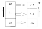
- FIG. 2 is a schematic diagram showing the distribution of the area of the cross section perpendicular to the air flow direction in the air flow path at the fresh air inlet in the air treatment apparatus shown in FIG. 1 and the corresponding distribution of each core fin group of the heat exchanger. is.
- FIG. 3 is a schematic diagram showing the detailed structure of the heat exchanger.
- FIG. 4 shows the distribution of the cross-sectional area perpendicular to the air flow direction in the air flow path at the new air port in the air treatment device according to the modification of the embodiment of the present invention, and the corresponding core fin groups of the heat exchanger. It is a schematic diagram showing the distribution of .
- the air treatment device 100 includes a case 10 having a fresh air port 11, an air supply port 12, a return air port 13, and an exhaust port 14.
- the case 10 contains fresh air.
- An air supply route RA from the inlet 11 to the air supply port 12 and an exhaust route RB from the return air port 13 to the exhaust port 14 are formed.
- 20 and an exhaust fan 30 are provided, the fresh air port 11 and the air supply port 12 are positioned diagonally on the case 10, the return air port 13 and the exhaust port 14 are positioned diagonally on the case 10,
- a heat exchanger 40 is provided at the intersection of the air supply route RA and the exhaust route RB to exchange heat between the air flowing through the air supply route RA and the air flowing through the air supply route RB.
- an internal circulation path RC from the return air port 13 to the air supply port 12 is further formed in the case 10 .
- the air treatment device 100 can not only treat the air in the room with outside air, but also can treat the air by directly using the room air.
- a cross section perpendicular to the air flow direction of the air flow path near the fresh air opening 11 is schematically illustrated as a block, and the long side direction of the block is defined as the first direction X.
- the first region Q1 is located substantially in the center in the first direction X
- the second region Q2 is located on both end sides in the first direction X
- the flow velocity of the air in the first region Q1 is the second region Q2 greater than the air velocity at
- the heat exchanger 40 used in the present embodiment is composed of a heat exchange core 41 and a cover plate 42.
- the heat exchange core 41 is composed of multi-layer heat exchange core fins and multi-layer heat exchange core fins alternately laminated in the first direction X.
- the heat exchange core 41 is composed of a membrane, wherein the heat exchange core 41 is mainly composed of paper made of special fibers by a special process, such paper has high moisture permeability, high airtightness, tear resistance, It has the characteristics of anti-aging and anti-mildew, and the gap between the fibers is small, so that only water vapor molecules with small particle size can pass through, so that the heat exchange core 41 achieves total heat exchange.
- the heat exchange core 41 is divided in the first direction X into a second core fin group 412, a first core fin group 411 and a second core fin group 412.
- the air supply passage RA1 and the exhaust passage RB1 in the heat exchanger 40 are separated from each other and intersect each other, so that the air in the air supply passage RA and the air in the exhaust passage RB can be sufficiently heat-exchanged. can.
- the first core fin group 411 is formed by alternately laminating a multilayer first core fin 411a and a multilayer first film 411b in the first direction X.
- An air supply passage RA1 through which the air of the air supply route RA circulates and an exhaust passage RB1 through which the air of the exhaust route RB circulates are formed between the membrane 411b.
- the intervals of the exhaust passage RB1 are all H1.
- the second core fin group 412 is formed by alternately laminating a multilayer second core fin 412a and a multilayer second film 412b in the first direction X.
- An air supply passage RA1 through which the air of the air supply route RA flows and an exhaust passage RB1 through which the air of the exhaust route RB flows are formed. are both H2, and H1 and H2 satisfy the relationship H1 ⁇ H2.
- the air in the first region Q1 flows into the first core fin group 411 of the heat exchanger 40 as indicated by the white arrow, and the air in the second region Q2 flows into the white arrow. , flows into the second core fin group 412 of the heat exchanger 40 .
- the dimension of the first region Q1 in the first direction X is substantially equal to the dimension of the first core fin group 411 in the first direction X
- the dimension of the second region Q2 in the first direction X is the dimension of the second core fin group 412. substantially equal to the dimension in the first direction X;
- the air in the air supply passage RA1 and the exhaust passage RB1 in the heat exchanger 40 can be independently heat-exchanged.
- the resistance received when the high-velocity air flowing out of the first region Q1 flows through the first core fin group 411 of the heat exchanger 40 is such that the low-velocity air flowing out of the second region Q2 passes through the heat exchanger 40. It is greater than the resistance received when flowing through the second core fin group 412 .
- the flow velocity distribution in the first direction X of the air that has flowed out after being heat-exchanged by the heat exchanger 40 becomes uniform, and the flow velocity distribution in the first direction X of the air on the inlet side of the heat exchanger 40 gradually increases. becomes uniform.
- the heat exchange in the first direction X of the heat exchanger 40 can be made uniform, and the heat exchange performance of the heat exchanger 40 as a whole can be improved.
- the heat exchange core fins divide the air supply route RA1 and the exhaust route RB1 into a plurality of branch passages,
- the dimension in the second direction Y of each branch passage in the first core fin group 411 is W1
- the dimension in the second direction Y of each branch passage in the second core fin group 412 is W2.
- W2 satisfy the relationship W1 ⁇ W2.
- the high-velocity air that has flowed out of the first region Q1 is caused to flow into the heat exchanger 40 in the second direction Y through the narrow branch passages, and at the same time, the low-velocity air that has flowed out of the second region Q2 is made to flow into the heat exchanger 40.
- the resistance that the air flowing out of the first region Q1 receives in the heat exchanger 40 is absorbed by the air flowing out of the second region Q2. It can be greater than the resistance encountered in exchanger 40 .
- the flow velocity distribution in the second direction Y of the air that has flowed out after being heat-exchanged by the heat exchanger 40 can be made uniform, and the flow velocity distribution of the air on the inlet side of the heat exchanger 40 in the first direction X can be made uniform.
- the flow velocity distribution also becomes uniform gradually.
- heat can be uniformly exchanged in the heat exchanger 40 in the second direction Y, and the heat exchange performance of the heat exchanger 40 as a whole can be improved.
- the air that flows out after being heat-exchanged by the heat exchanger 40 can make the flow velocity distribution more uniform.
- the dimension in the X direction, which is the first direction, of the air supply route RA1 and the exhaust route RB1 in the heat exchanger 40 is individually set, or the second dimension of the air supply route RA1 and the exhaust route RB1 in the heat exchanger 40 is set individually.
- the dimension in the Y direction, which is the direction, can also be set individually.
- a designer usually sets a predetermined average air supply amount q1 for an air treatment device, and matches the heat exchange areas S of the corresponding fans and heat exchangers based on the predetermined average air supply amount q1.
- the actual average air supply amount of the selected fan is set to q2, when q1>q2, it indicates that the pressure loss of the heat exchanger 40 is large. can be increased (i.e., the number m of combinations of the second core fins 412a and the second membranes 412b) in the heat exchanger 40 can be increased so as to reduce the , q1 ⁇ q2 indicates that the pressure loss of the heat exchanger 40 is small.
- the number of layers of the first core fin group 411 with a small interval in the heat exchanger 40 can be increased (that is, the number n of combinations of the first core fins 411a and the first membranes 411b can be increased).
- H1 is selected to be 2.0 mm and H2 to be 2.6 mm
- the air flowing through the first core fin group 411 and the air flowing through the second core fin group 412 can be sufficiently heat-exchanged, thereby making the heat exchange by the heat exchanger uniform, The performance of the entire heat exchanger can be improved.
- the air after heat exchange by the heat exchanger 40 flows into the room as uniformly as possible.
- the length L2 of the air flow path from the air port 11 to the inlet of the heat exchanger 40 is made smaller than the length L1 of the air flow path from the outlet of the heat exchanger 40 to the air supply port 12. is provided.
- the air that has flowed out of the heat exchanger 40 can be diffused as uniformly as possible before being introduced into the room through the air supply port 12 .
- the performance of the entire heat exchanger can be improved, and the heat exchange performance of the entire air treatment device can be improved.
- a first region Q1 with a high flow velocity and a second region Q2 with a low flow velocity are arranged along the first direction X in a cross section perpendicular to the air flow direction of the air flow path in the case 10.
- it is not limited thereto, and as shown in FIG. It can be further divided into a third region Q3 between Q2.
- the third A core fin group 413 is provided.
- the dimension in the first direction X of the first region Q1 is approximately equal to the dimension in the first direction X of the first core fin group 411
- the dimension in the first direction X of the second region Q2 is , the dimension in the first direction X of the second core fin group 412
- the dimension in the first direction X of the third region Q3 is approximately equal to the dimension in the first direction X of the third core fin group 413 .
- the cross section perpendicular to the air flow direction of the air flow path in the case 10 is further subdivided, and along the first direction X, the heat exchanger
- the flow velocity in the first direction X of the air after heat exchange by the heat exchanger 40 can be made more uniform.
- the heat exchange core fins of each layer of the heat exchange core 41 are made of paper, but the present invention is not limited to this, and the heat exchange core 41 is made of a material such as resin. and a moisture permeable membrane made of a polymer material.
- the first region where the air flow rate is high is the central region in the first direction
- the second region where the air flow rate is low is the region on both end sides in the first direction.
- the present invention is not limited to this, and the first region where the air flow rate is high may be the region on both end sides in the first direction, and the second region where the air flow rate is low may be the central region in the first direction. .
- the present invention is not limited to this, and may be divided into more regions.
- the dimension W1 in the second direction Y of each branch passage of the first core fin group 411 and the dimension W2 in the second direction Y of each branch passage of the second core fin group 412 satisfy W1 ⁇ W2.
- the present invention is not limited thereto, and the dimension W3 in the second direction Y of each branch passage of the third core fin group 413 satisfies the relationship W1 ⁇ W3 ⁇ W2. can be set as
- the first region is a region corresponding to the position of the fresh air port or the return air port in the first direction, but the present invention is not limited thereto, and the first region is It may be a region corresponding to the position of the fan volute in the first direction.
- the heat exchange cores may be assembled in combination in the form of core fin groups, independent core fins may be assembled layer by layer, and core fins with different spacing may be arranged in corresponding regions. It should be assembled so that the height is approximately the same.
- both the fresh air fan and the exhaust fan are provided horizontally, and the volute of the fresh air fan is located substantially in the center of the case in the first direction X.
- the area corresponding to the fresh air fan volute in the air supply path that enters from the fan air inlet and flows out from the fan air outlet is the second area where the air flow velocity is small, and the fresh air fan volute
- the area corresponding to the portion other than the first area is the first area where the air velocity is high, but the present invention is not limited to this.
- the area corresponding to the volute of the fresh air fan in the air supply path that is located substantially in the center of the second direction Y and enters from the intake port of the fan and flows out from the exhaust port of the fan is the second where the air flow velocity is low
- the area corresponding to the portion other than the volute of the fresh air fan may be the first area where the air velocity is high.
- the core fin group in the heat exchange core is laminated along the first direction X, but the present invention is not limited thereto, and the core fin group in the heat exchange core is provided in the second It may be provided in layers along the Y direction.
- heat exchanger is not limited to this, and a plurality of heat exchangers may be provided.
- Air treatment device 10 Case 11: Fresh air port 12: Air supply port 13: Return air port 14: Exhaust port 20: Fresh air fan 30: Exhaust fan 40: Heat exchanger 41: Heat exchange core 411: First Core fin group 411a: First core fin 411b: First membrane 412: Second core fin group 413: Third core fin group 412a: Second core fin 412b: Second membrane 42: Lid plate RA: Air supply path RB: Exhaust path RA1: Air supply Air passage RB1: Exhaust passage RC: Internal circulation route X: First direction Y: Second direction
Landscapes
- Engineering & Computer Science (AREA)
- Mechanical Engineering (AREA)
- General Engineering & Computer Science (AREA)
- Chemical & Material Sciences (AREA)
- Combustion & Propulsion (AREA)
- Physics & Mathematics (AREA)
- Thermal Sciences (AREA)
- Heat-Exchange Devices With Radiators And Conduit Assemblies (AREA)
- Filtering Of Dispersed Particles In Gases (AREA)
- Massaging Devices (AREA)
- Separation By Low-Temperature Treatments (AREA)
Priority Applications (4)
| Application Number | Priority Date | Filing Date | Title |
|---|---|---|---|
| JP2023515425A JPWO2022224878A1 (https=) | 2021-04-18 | 2022-04-12 | |
| AU2022262949A AU2022262949A1 (en) | 2021-04-18 | 2022-04-12 | Air treatment device |
| EP22791652.5A EP4328503A4 (en) | 2021-04-18 | 2022-04-12 | AIR TREATMENT DEVICE |
| US18/380,140 US20240035681A1 (en) | 2021-04-18 | 2023-10-13 | Air treatment device |
Applications Claiming Priority (2)
| Application Number | Priority Date | Filing Date | Title |
|---|---|---|---|
| CN202110415448.XA CN115218322B (zh) | 2021-04-18 | 2021-04-18 | 空气处理设备 |
| CN202110415448.X | 2021-04-18 |
Related Child Applications (1)
| Application Number | Title | Priority Date | Filing Date |
|---|---|---|---|
| US18/380,140 Continuation US20240035681A1 (en) | 2021-04-18 | 2023-10-13 | Air treatment device |
Publications (1)
| Publication Number | Publication Date |
|---|---|
| WO2022224878A1 true WO2022224878A1 (ja) | 2022-10-27 |
Family
ID=83605576
Family Applications (1)
| Application Number | Title | Priority Date | Filing Date |
|---|---|---|---|
| PCT/JP2022/017600 Ceased WO2022224878A1 (ja) | 2021-04-18 | 2022-04-12 | 空気処理装置 |
Country Status (6)
| Country | Link |
|---|---|
| US (1) | US20240035681A1 (https=) |
| EP (1) | EP4328503A4 (https=) |
| JP (1) | JPWO2022224878A1 (https=) |
| CN (1) | CN115218322B (https=) |
| AU (1) | AU2022262949A1 (https=) |
| WO (1) | WO2022224878A1 (https=) |
Citations (8)
| Publication number | Priority date | Publication date | Assignee | Title |
|---|---|---|---|---|
| JPS60238689A (ja) * | 1984-05-11 | 1985-11-27 | Mitsubishi Electric Corp | 熱交換器 |
| JPS63140295A (ja) * | 1986-11-30 | 1988-06-11 | Mikio Kususe | 対向流熱交換器 |
| JPH0618070A (ja) * | 1992-07-02 | 1994-01-25 | Mitsubishi Electric Corp | 換気装置 |
| JP2007315649A (ja) * | 2006-05-24 | 2007-12-06 | Mitsubishi Electric Corp | 全熱交換器 |
| WO2011030535A1 (ja) * | 2009-09-09 | 2011-03-17 | パナソニック株式会社 | 熱交換機器 |
| JP2012141121A (ja) * | 2010-12-16 | 2012-07-26 | Shimizu Corp | 全熱交換素子 |
| JP2013245871A (ja) * | 2012-05-25 | 2013-12-09 | Panasonic Corp | 熱交換気装置 |
| WO2014206483A1 (en) * | 2013-06-28 | 2014-12-31 | Electrolux Appliances Aktiebolag | Heat pump laundry dryer and method to optimize the heat exchange of such a heat pump laundry dryer |
Family Cites Families (11)
| Publication number | Priority date | Publication date | Assignee | Title |
|---|---|---|---|---|
| TW581227U (en) * | 2002-05-24 | 2004-03-21 | Ind Tech Res Inst | Full heat air-exchanging device |
| ATE502263T1 (de) * | 2002-07-22 | 2011-04-15 | Daikin Ind Ltd | Entfeuchtungselement und f r dieses verwendetes absorbierelement |
| KR100579373B1 (ko) * | 2003-11-24 | 2006-05-12 | 엘지전자 주식회사 | 환기장치의 열교환기에 사용되는 기능성 종이 |
| JP2008070070A (ja) * | 2006-09-15 | 2008-03-27 | Techno Frontier:Kk | 全熱交換器 |
| KR101151713B1 (ko) * | 2006-10-20 | 2012-06-15 | 삼성전자주식회사 | 환기장치 |
| KR20080073488A (ko) * | 2007-02-06 | 2008-08-11 | 삼성전자주식회사 | 환기장치 |
| DE102012201710A1 (de) * | 2011-02-14 | 2012-08-16 | Denso Corporation | Wärmetauscher |
| JP2013204913A (ja) * | 2012-03-28 | 2013-10-07 | Sharp Corp | 熱交換器 |
| CA3007452C (en) * | 2015-12-18 | 2018-10-23 | Core Energy Recovery Solutions Inc. | Enthalpy exchanger |
| JP2019027699A (ja) * | 2017-07-31 | 2019-02-21 | ダイキン工業株式会社 | 熱交換器、及び熱交換器の製造方法 |
| CN111380162A (zh) * | 2018-12-29 | 2020-07-07 | 大金工业株式会社 | 空气处理系统及其控制方法 |
-
2021
- 2021-04-18 CN CN202110415448.XA patent/CN115218322B/zh active Active
-
2022
- 2022-04-12 AU AU2022262949A patent/AU2022262949A1/en not_active Abandoned
- 2022-04-12 WO PCT/JP2022/017600 patent/WO2022224878A1/ja not_active Ceased
- 2022-04-12 JP JP2023515425A patent/JPWO2022224878A1/ja active Pending
- 2022-04-12 EP EP22791652.5A patent/EP4328503A4/en not_active Withdrawn
-
2023
- 2023-10-13 US US18/380,140 patent/US20240035681A1/en not_active Abandoned
Patent Citations (8)
| Publication number | Priority date | Publication date | Assignee | Title |
|---|---|---|---|---|
| JPS60238689A (ja) * | 1984-05-11 | 1985-11-27 | Mitsubishi Electric Corp | 熱交換器 |
| JPS63140295A (ja) * | 1986-11-30 | 1988-06-11 | Mikio Kususe | 対向流熱交換器 |
| JPH0618070A (ja) * | 1992-07-02 | 1994-01-25 | Mitsubishi Electric Corp | 換気装置 |
| JP2007315649A (ja) * | 2006-05-24 | 2007-12-06 | Mitsubishi Electric Corp | 全熱交換器 |
| WO2011030535A1 (ja) * | 2009-09-09 | 2011-03-17 | パナソニック株式会社 | 熱交換機器 |
| JP2012141121A (ja) * | 2010-12-16 | 2012-07-26 | Shimizu Corp | 全熱交換素子 |
| JP2013245871A (ja) * | 2012-05-25 | 2013-12-09 | Panasonic Corp | 熱交換気装置 |
| WO2014206483A1 (en) * | 2013-06-28 | 2014-12-31 | Electrolux Appliances Aktiebolag | Heat pump laundry dryer and method to optimize the heat exchange of such a heat pump laundry dryer |
Non-Patent Citations (1)
| Title |
|---|
| See also references of EP4328503A4 * |
Also Published As
| Publication number | Publication date |
|---|---|
| EP4328503A1 (en) | 2024-02-28 |
| US20240035681A1 (en) | 2024-02-01 |
| CN115218322B (zh) | 2024-05-24 |
| EP4328503A4 (en) | 2024-10-23 |
| AU2022262949A1 (en) | 2023-12-07 |
| JPWO2022224878A1 (https=) | 2022-10-27 |
| CN115218322A (zh) | 2022-10-21 |
Similar Documents
| Publication | Publication Date | Title |
|---|---|---|
| JP5126406B2 (ja) | 換気装置 | |
| CN101517346A (zh) | 热交换元件 | |
| US20250085004A1 (en) | Heat exchanging element and heat exchange ventilator | |
| WO2022224878A1 (ja) | 空気処理装置 | |
| WO2019244204A1 (ja) | 熱交換素子および熱交換換気装置 | |
| KR20080073488A (ko) | 환기장치 | |
| CN104321611B (zh) | 层叠型全热交换元件以及热交换换气装置 | |
| WO2022186302A1 (ja) | 熱交換器及び空気処理装置 | |
| JP2006250372A (ja) | 全熱交換器 | |
| KR102905969B1 (ko) | 전열교환기를 이용한 열회수장치. | |
| CN112097317B (zh) | 一种换热芯板、全热交换模块、换气装置和空调 | |
| WO2009110494A1 (ja) | 熱交換素子及びそれを用いた空気調和機または加熱・冷却装置 | |
| JP4391116B2 (ja) | 熱交換換気装置 | |
| KR100676258B1 (ko) | 전열교환기 | |
| JPH11316045A (ja) | 可変冷温風ミキシング分岐ダクト装置 | |
| CN214479899U (zh) | 一种燃气轮发电机的多风路结构 | |
| JPH0443245A (ja) | 熱交換気装置 | |
| JP2021036177A (ja) | 熱交換素子、及びそれを用いた熱交換形換気装置 | |
| CN115682783A (zh) | 热交换器和换气设备 | |
| WO2025141820A1 (ja) | 熱交換素子 | |
| JP2023065737A (ja) | 熱交換形換気装置 | |
| CN119063235A (zh) | 一种壳体组件及新风机 | |
| JP2001174172A (ja) | 熱交換素子 | |
| JPH02290493A (ja) | ヒートポンプ式ルームエアコン室内ユニットの熱交換器 | |
| CN115881070A (zh) | 低频吸声结构及通风散热设备 |
Legal Events
| Date | Code | Title | Description |
|---|---|---|---|
| 121 | Ep: the epo has been informed by wipo that ep was designated in this application |
Ref document number: 22791652 Country of ref document: EP Kind code of ref document: A1 |
|
| WWE | Wipo information: entry into national phase |
Ref document number: 2301006743 Country of ref document: TH |
|
| WWE | Wipo information: entry into national phase |
Ref document number: 2023515425 Country of ref document: JP |
|
| WWE | Wipo information: entry into national phase |
Ref document number: 2022262949 Country of ref document: AU Ref document number: AU2022262949 Country of ref document: AU |
|
| WWE | Wipo information: entry into national phase |
Ref document number: 2022791652 Country of ref document: EP |
|
| NENP | Non-entry into the national phase |
Ref country code: DE |
|
| ENP | Entry into the national phase |
Ref document number: 2022791652 Country of ref document: EP Effective date: 20231120 |
|
| ENP | Entry into the national phase |
Ref document number: 2022262949 Country of ref document: AU Date of ref document: 20220412 Kind code of ref document: A |
|
| WWW | Wipo information: withdrawn in national office |
Ref document number: 2022791652 Country of ref document: EP |