WO2022220215A1 - ボールねじ装置およびその製造方法 - Google Patents
ボールねじ装置およびその製造方法 Download PDFInfo
- Publication number
- WO2022220215A1 WO2022220215A1 PCT/JP2022/017477 JP2022017477W WO2022220215A1 WO 2022220215 A1 WO2022220215 A1 WO 2022220215A1 JP 2022017477 W JP2022017477 W JP 2022017477W WO 2022220215 A1 WO2022220215 A1 WO 2022220215A1
- Authority
- WO
- WIPO (PCT)
- Prior art keywords
- stopper
- axial
- ball screw
- axial direction
- screw device
- Prior art date
- Legal status (The legal status is an assumption and is not a legal conclusion. Google has not performed a legal analysis and makes no representation as to the accuracy of the status listed.)
- Ceased
Links
Images


Classifications
-
- F—MECHANICAL ENGINEERING; LIGHTING; HEATING; WEAPONS; BLASTING
- F16—ENGINEERING ELEMENTS AND UNITS; GENERAL MEASURES FOR PRODUCING AND MAINTAINING EFFECTIVE FUNCTIONING OF MACHINES OR INSTALLATIONS; THERMAL INSULATION IN GENERAL
- F16H—GEARING
- F16H25/00—Gearings comprising primarily only cams, cam-followers and screw-and-nut mechanisms
- F16H25/18—Gearings comprising primarily only cams, cam-followers and screw-and-nut mechanisms for conveying or interconverting oscillating or reciprocating motions
- F16H25/20—Screw mechanisms
- F16H25/24—Elements essential to such mechanisms, e.g. screws, nuts
-
- F—MECHANICAL ENGINEERING; LIGHTING; HEATING; WEAPONS; BLASTING
- F16—ENGINEERING ELEMENTS AND UNITS; GENERAL MEASURES FOR PRODUCING AND MAINTAINING EFFECTIVE FUNCTIONING OF MACHINES OR INSTALLATIONS; THERMAL INSULATION IN GENERAL
- F16H—GEARING
- F16H25/00—Gearings comprising primarily only cams, cam-followers and screw-and-nut mechanisms
- F16H25/18—Gearings comprising primarily only cams, cam-followers and screw-and-nut mechanisms for conveying or interconverting oscillating or reciprocating motions
- F16H25/20—Screw mechanisms
- F16H25/2015—Means specially adapted for stopping actuators in the end position; Position sensing means
-
- F—MECHANICAL ENGINEERING; LIGHTING; HEATING; WEAPONS; BLASTING
- F16—ENGINEERING ELEMENTS AND UNITS; GENERAL MEASURES FOR PRODUCING AND MAINTAINING EFFECTIVE FUNCTIONING OF MACHINES OR INSTALLATIONS; THERMAL INSULATION IN GENERAL
- F16H—GEARING
- F16H25/00—Gearings comprising primarily only cams, cam-followers and screw-and-nut mechanisms
- F16H25/18—Gearings comprising primarily only cams, cam-followers and screw-and-nut mechanisms for conveying or interconverting oscillating or reciprocating motions
- F16H25/20—Screw mechanisms
- F16H25/22—Screw mechanisms with balls, rollers, or similar members between the co-operating parts; Elements essential to the use of such members
- F16H25/2204—Screw mechanisms with balls, rollers, or similar members between the co-operating parts; Elements essential to the use of such members with balls
-
- F—MECHANICAL ENGINEERING; LIGHTING; HEATING; WEAPONS; BLASTING
- F16—ENGINEERING ELEMENTS AND UNITS; GENERAL MEASURES FOR PRODUCING AND MAINTAINING EFFECTIVE FUNCTIONING OF MACHINES OR INSTALLATIONS; THERMAL INSULATION IN GENERAL
- F16H—GEARING
- F16H25/00—Gearings comprising primarily only cams, cam-followers and screw-and-nut mechanisms
- F16H25/18—Gearings comprising primarily only cams, cam-followers and screw-and-nut mechanisms for conveying or interconverting oscillating or reciprocating motions
- F16H25/20—Screw mechanisms
- F16H25/24—Elements essential to such mechanisms, e.g. screws, nuts
- F16H2025/2481—Special features for facilitating the manufacturing of spindles, nuts, or sleeves of screw devices
-
- F—MECHANICAL ENGINEERING; LIGHTING; HEATING; WEAPONS; BLASTING
- F16—ENGINEERING ELEMENTS AND UNITS; GENERAL MEASURES FOR PRODUCING AND MAINTAINING EFFECTIVE FUNCTIONING OF MACHINES OR INSTALLATIONS; THERMAL INSULATION IN GENERAL
- F16H—GEARING
- F16H25/00—Gearings comprising primarily only cams, cam-followers and screw-and-nut mechanisms
- F16H25/18—Gearings comprising primarily only cams, cam-followers and screw-and-nut mechanisms for conveying or interconverting oscillating or reciprocating motions
- F16H25/20—Screw mechanisms
- F16H25/2021—Screw mechanisms with means for avoiding overloading
Definitions
- the present invention relates to a ball screw device and its manufacturing method.
- a ball screw device causes balls to roll between the screw shaft and the nut, so it is more efficient than a slide screw device that directly contacts the screw shaft and the nut. For this reason, the ball screw device converts rotary motion of a drive source such as an electric motor into linear motion, and is used in various mechanical devices such as electric brake devices and automatic manual transmissions (AMT) of automobiles, and positioning devices of machine tools. built in.
- AMT automatic manual transmissions
- a ball screw device includes a screw shaft having a spiral shaft-side ball screw groove on its outer peripheral surface, a nut having a spiral nut-side ball screw groove on its inner peripheral surface, and a shaft-side ball screw groove and a nut-side ball screw groove. and a plurality of balls disposed between.
- a ball screw device uses one of a screw shaft and a nut as a rotary motion element, and the other of the screw shaft and a nut as a linear motion element, depending on the application.
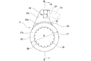
- FIG. 22 shows a conventional ball screw device 100 having a structure for regulating the stroke end of a linear motion element, which is described in Japanese Unexamined Patent Application Publication No. 2016-70281.
- the ball screw device 100 includes a screw shaft 101, a nut 102, a plurality of balls (not shown), and a stopper 103.
- the threaded shaft 101 has a threaded portion 104 and a fitting shaft portion 105 arranged adjacent to one side of the threaded portion 104 in the axial direction.
- the screw portion 104 has a spiral shaft-side ball screw groove 106 on its outer peripheral surface.
- the fitting shaft portion 105 has an outer diameter smaller than that of the threaded portion 104 and has male spline teeth at a plurality of circumferentially equally spaced locations on the outer peripheral surface.
- the threaded shaft 101 is arranged coaxially with the nut 102 with the threaded portion 104 inserted inside the nut 102 .
- the nut 102 has a cylindrical shape, and has a spiral nut-side ball screw groove (not shown) and a substantially S-shaped circulation groove on the inner peripheral surface.
- the nut 102 has a first engaging portion 107 at one end in the axial direction.
- the shaft-side ball screw groove 106 and the nut-side ball screw groove are arranged so as to face each other in the radial direction, forming a spiral load path.
- the start point and end point of the load path are connected by a circulation groove formed on the inner peripheral surface of the nut 102 . Therefore, the ball that has reached the end point of the load path is returned to the start point of the load path through the circulation groove.
- the start point and end point of the load path are interchanged according to the direction of relative displacement between the screw shaft 101 and the nut 102 in the axial direction.
- the stopper 103 has a boss portion 108 having an annular shape and a second engaging portion 109 having a projection shape.
- the boss portion 108 is fitted on the fitting shaft portion 105 of the screw shaft 101 so as not to rotate relative to the fitting shaft portion 105 .
- the boss portion 108 spline-engages the female spline teeth formed on the inner peripheral surface with the male spline teeth formed on the outer peripheral surface of the fitting shaft portion 105 so that the fitting shaft It is fitted to the portion 105 so as not to be relatively rotatable.
- the second engaging portion 109 radially protrudes from a portion of the outer peripheral surface of the boss portion 108 in the circumferential direction.
- the stopper 103 is used only to restrict the stroke end of the linear motion element.
- both side surfaces of the stopper 103 in the axial direction are formed into flat surfaces.
- the axial side surface of the boss portion 108 and the axial side surface of the second engaging portion 109 are positioned on the same plane.
- one axial side surface of the stopper 103 including the one axial side surface of the second engaging portion 109 is used.
- the entire side surface contacts the clamping member. Since the second engaging portion 109 is provided only on a part of the outer peripheral surface of the boss portion 108 in the circumferential direction, the contact surface of the stopper 103 with respect to the holding member is rotationally asymmetric with respect to the central axis of the stopper 103. Become. Therefore, the stopper 103 may be applied with an unbalanced load or a moment load.
- second engaging portion 109 extends from central axis O of stopper 103 .
- the screw shaft 101 to which the stopper 103 is fitted is likely to be tilted, making it difficult to evenly apply the load to the balls rolling on the load path. As a result, the service life of the ball screw device 100 may be shortened.
- a ball screw device includes a screw shaft, a nut, a plurality of balls, a stopper, and a holding member.
- the screw shaft includes a threaded portion having a helical shaft-side ball screw groove on an outer peripheral surface thereof, and a fitting shaft portion having an outer diameter smaller than that of the threaded portion and disposed adjacent to one axial side of the threaded portion.
- the nut has a helical nut-side ball screw groove on its inner peripheral surface, and a first engaging portion at one end in the axial direction.
- the plurality of balls are arranged between the shaft-side ball screw groove and the nut-side ball screw groove.
- the stopper protrudes in a radial direction from a boss portion that is fitted to the fitting shaft portion so as not to rotate relative to the boss portion, and is engageable with the first engaging portion in the circumferential direction. and a second engaging portion.
- the holding member is arranged adjacent to one axial side of the stopper and axially holds the stopper between itself and the threaded portion.
- a ball screw device transmits an axial load between the screw portion and the clamping member via the stopper without applying a moment to the stopper.
- the stopper is configured by a flat surface on one side surface in the axial direction, which exists on an imaginary plane orthogonal to the central axis of the stopper, and the center of the stopper. It may have a first contact surface contacting the clamping member having a shape rotationally symmetrical about an axis, and a flat surface existing on an imaginary plane orthogonal to the central axis of the stopper on the side surface on the other side in the axial direction. It can have a second contact surface which is configured by a surface, has a rotationally symmetrical shape with respect to the central axis of the stopper, and contacts the threaded portion.
- the first contact surface is configured from a side surface on one axial direction side of the boss portion
- the second contact surface is configured from a side surface on the other axial direction side of the boss portion.
- the side surface on one axial side of the second engaging portion is shifted axially to the other side in the axial direction with respect to the side surface on one axial side of the boss portion. and the side surface of the second engaging portion on the other axial side is displaced axially to the one axial side with respect to the side surface of the boss portion on the other axial direction. be able to.
- the side surface on the one axial side of the second engaging portion can be connected to the side surface on the one axial side of the boss portion via a stepped portion having an arcuate cross-sectional shape.
- the side surface on the other axial side of the second engaging portion can be connected to the side surface on the other axial side of the boss portion via a stepped portion having an arcuate cross-sectional shape.
- the amount of positional deviation of the side surface on the other axial side of the second engaging portion toward the one axial side with respect to the side surface on the side of the second engaging portion can be the same.
- the side surface on one side in the axial direction and the side surface on the other side in the axial direction of the stopper can be mirror symmetrical.
- the axial thickness of the second engaging portion can be made constant over the radial direction.
- the axial thickness of the second engaging portion can be made smaller toward the radially outer side.
- the side surface that engages with the first engaging portion in the circumferential direction is It can be smoothly connected to the outer peripheral surface of the boss portion via a concave curved surface having an arc-shaped contour shape, and the first engaging portion can be smoothly connected to the outer peripheral surface of the boss portion, and the first engaging portion
- the side surface on the side not engaged in the circumferential direction with the joining portion can be connected to the outer peripheral surface of the boss portion in the tangential direction of the outer peripheral surface of the boss portion when viewed from the axial direction.
- the fitting shaft portion may have a width across flat shape having a pair of flat outer surfaces parallel to each other on the outer peripheral surface
- the boss portion may have an inner peripheral surface.
- the fitting shaft portion can have male spline teeth on its outer peripheral surface
- the boss portion can have an engagement hole with female spline teeth on its inner peripheral surface
- the stopper can be loosely fitted on the fitting shaft portion so as to allow relative displacement in the axial direction, and the holding member can be attached to the screw shaft. , for example, can be fitted onto the fitting shaft by press-fitting.
- the stopper can be fitted onto the fitting shaft portion by press fitting, and the holding member can be fitted onto the screw shaft, for example, the fitting shaft portion by press fitting. .
- the screw shaft can be a rotary motion element that rotates during use
- the nut can be a linear motion element that linearly moves during use
- the clamping member may be a driving member for rotationally driving the screw shaft or a rolling bearing for rotatably supporting the screw shaft.
- the drive member can consist of a gear, pulley, sprocket or motor shaft.
- the screw shaft may be a linear motion element that performs linear motion during use
- the nut may be a rotary motion element that performs rotational motion during use
- the clamping member can be a piston that linearly moves together with the screw shaft.
- a method for manufacturing a ball screw device is a method for manufacturing a ball screw device according to one aspect of the present invention, in which an intermediate material having the approximate shape of the stopper is formed by forging a material. After forming, the step of machining both sides in the axial direction of the intermediate material to manufacture the stopper is provided.
- both sides of the intermediate material in the axial direction are machined to form the first contact surface and the second contact surface.
- the axial load can be transmitted between the threaded portion and the clamping member via the stopper without applying a moment to the stopper.
- Axial loads can be transferred between the threaded portion and the clamping member without causing any interference.
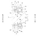
- FIG. 1 is an axial front view of a ball screw device according to a first embodiment of the present invention.
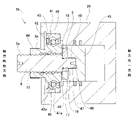
- FIG. 2 is a cross-sectional view taken along line AA of FIG. 3 is a partially enlarged view of FIG. 2.
- FIG. FIG. 4 is a perspective view showing the ball screw device according to the first example, omitting the driving member.
- FIG. 5 is a front view of the stopper that constitutes the ball screw device of the first example, viewed from one side in the axial direction. 6 is a cross-sectional view taken along the line BB of FIG. 5.
- FIG. FIG. 7 is a perspective view of the stopper of the first example.
- FIG. 8 is a diagram corresponding to FIG. 5 for the stopper of the second example.
- FIG. 9 is a diagram corresponding to FIG. 6 for the stopper of the second example.
- FIG. 10 is a diagram corresponding to FIG. 7 for the stopper of the second example.
- FIG. 11 is a diagram corresponding to FIG. 5 for the stopper of the third example.
- FIG. 12 is a diagram corresponding to FIG. 6 for the stopper of the third example.
- FIG. 13 is a diagram corresponding to FIG. 7 for the stopper of the third example.
- FIG. 14A is a diagram corresponding to FIG. 4 for a ball screw device of a fourth example
- FIG. 14B is a diagram corresponding to FIG. 4 for a ball screw device of a modification of the fourth example. is.
- FIG. 15 is a diagram corresponding to FIG.
- FIG. 16A is a diagram corresponding to FIG. 4 for a ball screw device of a fifth example
- FIG. 16B is a diagram corresponding to FIG. 4 for a ball screw device of a modification of the fifth example.
- FIG. 17 is a view corresponding to FIG. 7 of the stopper that constitutes the ball screw device of the fifth example
- FIG. 18 is a diagram corresponding to FIG. 2 of the stopper that constitutes the ball screw device of the sixth example.
- FIG. 19 is a diagram corresponding to FIG. 3 for the stopper of the sixth example.
- FIG. 20 is a view corresponding to FIG. 2 of the stopper that constitutes the ball screw device of the seventh example.
- FIG. 21 is a diagram corresponding to FIG. 3 for the stopper of the seventh example.
- FIG. 22 is a perspective view showing a conventional ball screw device.
- FIG. 23 is a cross-sectional view of a stopper that constitutes a conventional ball screw device, for explaining the problem of the conventional ball screw device.
- FIG. 1 A first example of an embodiment of the present invention will be described with reference to FIGS. 1 to 7.
- FIG. 1 A first example of an embodiment of the present invention will be described with reference to FIGS. 1 to 7.
- the ball screw device 1 of this example is incorporated in, for example, an electric brake booster device and used for applications such as converting rotary motion of an electric motor, which is a drive source, into linear motion to operate a piston of a hydraulic cylinder.
- the ball screw device 1 includes a screw shaft 2, a nut 3, a plurality of balls 4, a stopper 5, and a drive member 6 corresponding to a holding member.
- the screw shaft 2 constitutes a rotational motion element that rotates during use
- the nut 3 constitutes a linear motion element that linearly moves during use. That is, the ball screw device 1 of this example is used in a mode in which the screw shaft 2 is rotationally driven and the nut 3 is linearly moved.
- the screw shaft 2 is inserted inside the nut 3 and arranged coaxially with the nut 3 .
- a spiral load path 7 is provided between the outer peripheral surface of the screw shaft 2 and the inner peripheral surface of the nut 3 .
- a plurality of balls 4 are rotatably arranged in the load path 7 .
- axial direction, radial direction and circumferential direction refer to the axial direction, radial direction and circumferential direction with respect to the screw shaft unless otherwise specified. 2, 3 and 6 and the left side in FIG. 4, and the other axial side is the left side in FIGS. 2, 3 and 6 and the right side in FIG. Point.
- the threaded shaft 2 is made of metal and has a threaded portion 9 and a fitting shaft portion 10 arranged adjacent to one side of the threaded portion 9 in the axial direction.
- the threaded portion 9 and the fitting shaft portion 10 are coaxially arranged and integrally formed with each other.
- the fitting shaft portion 10 has an outer diameter smaller than that of the threaded portion 9 . Therefore, the screw shaft 2 has a stepped surface 11 facing one side in the axial direction between the threaded portion 9 and the fitting shaft portion 10 .
- the stepped surface 11 is formed by a side surface on one axial side of the threaded portion 9 , that is, a flat surface existing on a virtual plane perpendicular to the central axis of the screw shaft 2 .
- the screw portion 9 has a spiral shaft-side ball screw groove 12 on its outer peripheral surface.
- the shaft-side ball screw groove 12 is formed by subjecting the outer peripheral surface of the threaded portion 9 to grinding, cutting, or rolling.
- the number of threads of the shaft-side ball screw groove 12 is one.
- the shaft-side ball screw groove 12 has a Gothic arch or circular arc groove shape.
- the fitting shaft portion 10 has a plurality of male spline teeth 13 on its outer peripheral surface.
- the male spline teeth 13 are arranged at a plurality of locations on the outer peripheral surface of the fitting shaft portion 10 at equal intervals in the circumferential direction. That is, the fitting shaft portion 10 is configured by a spline shaft portion.
- each male spline tooth 13 is formed by an involute spline tooth, but it can also be formed by an angular spline tooth or a serration.
- the screw shaft 2 is arranged coaxially with the nut 3 with the threaded portion 9 inserted inside the nut 3 .
- the screw shaft 2 is composed of the threaded portion 9 and the fitting shaft portion 10.
- the screw shaft is rotatably supported on the housing or the like. It is also possible to provide a second fitting shaft portion or the like for fixing a rolling bearing or the like.
- the nut 3 is made of metal and has a cylindrical shape as a whole.
- the nut 3 has a helical nut-side ball screw groove 14 and a circulation groove 8 on its inner peripheral surface.
- the nut-side ball screw groove 14 has a spiral shape.
- the nut-side ball screw groove 14 is formed by subjecting the inner peripheral surface of the nut 3 to, for example, grinding, cutting, rolling tapping, or cutting tapping.
- the nut-side ball screw groove 14 has the same lead as the shaft-side ball screw groove 12 . Therefore, in a state in which the threaded portion 9 of the screw shaft 2 is inserted inside the nut 3, the shaft-side ball screw groove 12 and the nut-side ball screw groove 14 are arranged so as to face each other in the radial direction, forming a spiral shape. composes the load path 7 of.
- the number of threads of the nut-side ball screw groove 14 is one, like the shaft-side ball screw groove 12 .
- the nut-side ball screw groove 14 has a Gothic arch or circular arc groove shape.
- the circulation groove 8 has a substantially S-shape.
- the circulation groove 8 is formed in the inner peripheral surface of the nut 3 by cold forging, for example.
- the circulation groove 8 smoothly connects axially adjacent portions of the nut-side ball screw groove 14 and connects the start point and the end point of the load path 7 . Therefore, the ball 4 that has reached the end point of the load path 7 is returned to the start point of the load path 7 through the circulation groove 8 .
- the start point and end point of the load path 7 are interchanged according to the relative displacement direction of the screw shaft 2 and the nut 3 in the axial direction, in other words, the relative rotation direction of the screw shaft 2 and the nut 3 .
- the circulation groove 8 has a substantially semicircular cross-sectional shape.
- the circulation groove 8 has a groove width slightly larger than the diameter of the balls 4, and a groove depth that allows the balls 4 moving in the circulation groove 8 to climb over the thread of the shaft-side ball screw groove 12. have.
- the nut 3 has a first engaging portion 15 at one end in the axial direction.
- the first engaging portion 15 is provided at a part of the circumference of the end of the nut 3 on one side in the axial direction, and protrudes from the cylindrical body portion toward the one side in the axial direction.
- the first engaging portion 15 has a fan column shape, and has an axial protrusion amount that is approximately the same as the axial thickness dimension of the stopper 5 .
- the first engaging portion 15 has a flat first stopper surface 16 on one circumferential side surface (left side surface in FIG. 4).
- the first stopper surface 16 is arranged substantially parallel to the central axis of the nut 3 .
- the nut 3 is integrally constructed as a whole including the first engaging portion 15 .
- a cylindrical main body portion having a nut-side ball screw groove on the inner peripheral surface and a first engaging portion configured separately from the main body portion are attached to the main body portion. It can also be fixed against.
- the ball screw device 1 of this example uses the nut 3 as a linear motion element. Therefore, in this example, the nut 3 is prevented from rotating by a non-illustrated anti-rotation mechanism.
- the anti-rotation mechanism conventionally known various structures can be adopted. It is possible to employ a structure that engages with the concave groove 50 formed in the direction.
- Balls 4 are steel balls having a predetermined diameter, and are arranged in load path 7 and circulation groove 8 so as to be able to roll.
- the balls 4 arranged in the load path 7 roll while being subjected to a compressive load, whereas the balls 4 arranged in the circulation groove 8 are pushed by the succeeding balls 4 and roll without receiving a compressive load. move.
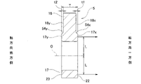
- the stopper 5 is made of metal and has a substantially six-character shape as a whole.
- the stopper 5 of this example not only has the function of regulating the stroke end of the nut 3, which is a linear motion element, but also has the function of transmitting an axial load between the threaded portion 9 and the drive member 6 arranged on both sides in the axial direction. have.
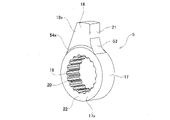
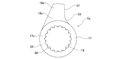
- the stopper 5 has a boss portion 17 having an annular shape and a second engaging portion 18 having a projection shape.
- the boss portion 17 is fitted on the fitting shaft portion 10 of the screw shaft 2 so as not to be relatively rotatable.
- the boss portion 17 has an engagement hole 19 in its radial center portion, through which the fitting shaft portion 10 can be axially inserted.
- the engagement hole 19 has a plurality of female spline teeth 20 on its inner peripheral surface.
- the female spline teeth 20 are arranged on the inner peripheral surface of the engagement hole 19 at a plurality of locations at regular intervals in the circumferential direction. That is, the engaging hole 19 is configured by a spline hole.
- the boss portion 17 is loosely spline-engaged with the fitting shaft portion 10 to allow relative displacement in the axial direction. It is also possible to have a spline fit.
- the axial thickness of the boss portion 17 is sufficiently smaller than the axial dimension of the fitting shaft portion 10 .
- the boss portion 17 has a cylindrical outer peripheral surface and has an outer diameter that is approximately the same as the outer diameter of the stepped surface 11 provided on the screw shaft 2 .
- the second engaging portion 18 is provided on a portion of the outer peripheral surface of the boss portion 17 in the circumferential direction and protrudes radially outward.
- the outer peripheral surface of the second engaging portion 18 is formed in a partially cylindrical surface shape, and has a circumscribed circle diameter substantially the same as the outer diameter of the nut 3 .
- the second engaging portion 18 has a flat second stopper surface 21 on the other circumferential side surface (the right side surface in FIG. 5).
- the second stopper surface 21 comes into surface contact with the first stopper surface 16 when the nut 3 has moved relative to the screw shaft 2 in one axial direction and reached the stroke end. Therefore, in this example, the second stopper surface 21 is arranged substantially parallel to the central axis of the stopper 5 .
- the side surface of the second engaging portion 18 on the other side in the circumferential direction corresponds to the side surface on the side that engages with the first engaging portion 15 in the circumferential direction
- the side surface on one side in the circumferential direction of the second engaging portion 18 corresponds to the side surface on the side that does not engage with the first engaging portion 15 in the circumferential direction.
- the second stopper surface 21 and the outer peripheral surface of the boss portion 17 are smoothly connected via a concave curved surface 53 having an arc-shaped profile when viewed from the axial direction.
- the radius of curvature R of the concave curved surface 53 is set to the largest possible value within the range that satisfies the following first and second conditions.
- the first condition is that the radial dimension L 21 of the second stopper surface 21 is larger than the radial dimension L 16 of the first stopper surface 16 (L 21 >L 16 ).
- the second condition is that the difference (L 21 ⁇ L 16 ) between the radial dimension L 21 of the second stopper surface 21 and the radial dimension L 16 of the first stopper surface 16 is equal to the radial dimension of the first stopper surface 16.
- the condition is that it is 1/10 times or more of L 16 (L 21 ⁇ L 16 ⁇ 1/10 ⁇ L 16 ).
- the magnitude of the radius of curvature R of the concave surface 53 is set so as to satisfy the first and second conditions.
- the radius of curvature R of the concave curved surface 53 is preferably 1/5 to 1/2 times the diameter D of the boss portion 17.
- the radius of curvature R of the concave curved surface 53 is , which is about 1/3 times the diameter D of the boss portion 17 .
- a side surface (left side surface in FIG. 5) of the second engaging portion 18 on one side in the circumferential direction is formed in a flat surface shape and extends in a tangential direction of the outer peripheral surface of the boss portion 17 . Therefore, the side surface on one side in the circumferential direction of the second engaging portion 18 is connected to the outer peripheral surface of the boss portion 17 in the tangential direction of the outer peripheral surface of the boss portion 17 when viewed from the axial direction.
- the second engaging portion 18 has a tapered shape in which the width in the circumferential direction decreases from the radially inner side to the radially outer side, in other words, it has a substantially trapezoidal end face shape when viewed in the axial direction.
- the side surface on one side in the circumferential direction of the second engaging portion is smoothly connected to the outer peripheral surface of the boss portion, that is, when viewed from the axial direction, the outer peripheral surface of the boss portion and the tangent line to the outer peripheral surface of the boss portion at the connection portion to the one circumferential side surface of the second engaging portion is the same straight line.
- the side surface on one side in the circumferential direction of the second engaging portion may be configured by a convex curved surface having a radius of curvature larger than the radius of curvature of the outer peripheral surface of the boss portion.
- the axial thickness of the second engaging portion 18 is constant in the radial direction and is smaller than the axial thickness of the boss portion 17 . Therefore, the side surface 18x on the one axial side of the second engaging portion 18 is displaced from the side surface 17x on the one axial side of the boss portion 17 in the axial direction on the other side in the axial direction.
- a side surface 18 y of the second engaging portion 18 on the other side in the axial direction is arranged so as to be shifted axially to the one side in the axial direction with respect to a side surface 17 y on the other side in the axial direction of the boss portion 17 .
- the side surface 17x on the one axial side of the boss portion 17 protrudes in the axial direction from the side surface 18x on the one axial side of the second engaging portion 18.
- the side surface 17y of the second engaging portion 18 protrudes in the axial direction from the side surface 18y of the second engaging portion 18 on the other side in the axial direction.
- each of the side surfaces on both sides in the axial direction of the stopper 5 has a stepped shape instead of a flat surface.
- a side surface 17x on one axial side of the boss portion 17 and a side surface 18x on one axial side of the second engaging portion 18 are connected via a stepped portion 54x having an arcuate cross-sectional shape.
- a side surface 17y on the other axial side of the boss portion 17 and a side surface 18y on the other axial side of the second engaging portion 18 are connected via a stepped portion 54y having an arcuate cross-sectional shape.
- the radius of curvature of each of the stepped portions 54x and 54y is about 1/25 to 1/2 times the axial dimension T of the stopper 5, preferably 1/10 to 1/3 times. It is set to a value of degree.
- the side surface of the stopper 5 on one side in the axial direction and the side surface on the other side in the axial direction are mirror symmetrical. As a result, even if the second engaging portion 18 contacts the first engaging portion 15 and is deformed, the second engaging portion 18 will still be in contact with the nut 3 and the driving member. 6 can be prevented, and the mounting state of the stopper 5 can be stabilized.
- the positional deviation amounts t1 and t2 of the axial side surfaces 18x and 18y of the second engaging portion 18 are approximately 1/20 to 1/5 times the axial dimension T of the stopper 5, preferably 1/15. It is set to a small value of about double to 1/8 times.
- the axial dimension T of the stopper 5 is set to 5 mm
- the displacement amounts t1 and t2 of the side surface 18x on one axial side and the side surface 18y on the other axial side of the second engaging portion 18 are set to 0.5 mm. It is set to 5 mm.
- one axial side surface of the boss portion 17 having an annular shape protrudes in the axial direction from the side surface 18 x of the second engaging portion 18 on the one axial side side of the stopper 5 .
- the side surface 17x is used as a first contact surface 22 that contacts an annular surface 28 of the driving member 6, which will be described later.
- a side surface 17y on the other axial side of the boss portion 17 having an annular shape and protruding in the axial direction from the side surface 18y on the other axial side of the second engaging portion 18. is a second contact surface 23 that contacts the stepped surface 11 of the threaded portion 9 .
- the first contact surface 22 is composed of a flat surface that exists on a virtual plane perpendicular to the central axis of the stopper 5 and has a rotationally symmetrical shape with respect to the central axis of the stopper 5 . Specifically, the first contact surface 22 has n-fold symmetry (n is the number of female spline teeth formed on the inner peripheral surface of the engagement hole 19).
- the second contact surface 23 is composed of a flat surface existing on a virtual plane perpendicular to the central axis of the stopper 5 and has a rotationally symmetrical shape with respect to the central axis of the stopper 5 . Specifically, the second contact surface 23 has n-fold symmetry (n is the number of female spline teeth formed on the inner peripheral surface of the engagement hole 19).
- the first contact surface 22 and the second contact surface 23 each have a circular outer peripheral edge and an uneven inner peripheral edge, and have the same shape and size.
- the stopper 5 of this example as described above has a symmetrical shape with respect to the axial direction (left-right symmetrical in FIG. 6).
- the stopper 5 of this example as described above can be manufactured, for example, as follows. First, for example, a metal material having a cylindrical shape is subjected to a plurality of stages of forging, such as cold forging, so that the shape of the material is gradually plastically deformed into the approximate shape of the stopper 5 , thereby forming the stopper 5 .
- An intermediate blank having a general shape is constructed. That is, by subjecting the material to forging, an intermediate material having an annular boss portion having a plurality of female spline teeth on the inner peripheral surface and a projecting second engaging portion is obtained.
- the side surfaces on both sides in the axial direction of the intermediate material are each subjected to machining such as cutting and grinding.
- machining such as cutting and grinding.
- the flatness of both sides of the boss in the axial direction is improved, and the first contact surface 22 and the second contact surface 23 are formed on both sides of the boss in the axial direction.
- the stopper 5, which is a finished product is obtained.
- the side surfaces on both sides in the axial direction of the second engaging portion can be used as they are after forging. However, the side surfaces on both axial sides of the second engaging portion can also be machined, such as by cutting or grinding.
- the amount of positional deviation t1 and the amount of positional deviation t2 When at least one of the amount of positional deviation t1 and the amount of positional deviation t2 is set to a large value, the amount of elongation (the amount of crushing) of the material during forging processing becomes large, and the stress in the axial direction concentrates, causing the second engagement to occur. Cracks are likely to occur at the boundary between the portion 18 and the boss portion 17 . As in this example, if the positional deviation amounts t1 and t2 of the axial side surfaces 18x and 18y of the second engaging portion 18 with respect to the axial dimension T of the stopper 5 are set small, the occurrence of cracks can be prevented.
- the position of the side surface on one axial side of the second engaging portion with respect to the side surface on the one axial side of the boss portion toward the other side in the axial direction as long as it is possible to prevent the occurrence of cracks. It is also possible to make the amount of displacement different from the positional displacement amount of the side surface of the second engaging portion on the other axial side with respect to the side surface of the boss portion on the other axial side.
- the drive member 6 is a member such as a gear or a pulley, and rotates the screw shaft 2 by transmitting torque input from a drive source such as an electric motor to the screw shaft 2 .
- the driving member 6 is arranged adjacent to one side of the stopper 5 in the axial direction, and sandwiches the stopper 5 in the axial direction with the threaded portion 9 .
- the driving member 6 has a disc portion 24 and a cylindrical tubular portion 25 .
- the disc portion 24 has a mounting hole 26 that penetrates in the axial direction at the center portion in the radial direction.
- the mounting hole 26 has a plurality of female spline teeth 27 on its inner peripheral surface.
- the female spline teeth 27 are arranged at a plurality of circumferentially equal intervals on the inner peripheral surface of the mounting hole 26 . That is, the mounting hole 26 is configured by a spline hole.
- the disk portion 24 is spline-engaged with the mounting hole 26 with a portion of the fitting shaft portion 10 that is deviated from the portion where the stopper 5 is fitted to the fitting shaft portion 10 in the axial direction. are fitted on the outside so that they cannot rotate relative to each other.
- the fitting shaft portion 10 is press-fitted into the mounting hole 26 of the disk portion 24 to be spline-engaged.
- the fitting shaft portion is loosely spline-engaged with the mounting hole of the drive member, and the lock nut is screwed to the portion of the fitting shaft portion that protrudes to one side in the axial direction from the disc portion of the drive member. Axial displacement of the drive member with respect to the screw shaft can also be prevented by mating or locking the retaining ring.
- the disk portion 24 has an annular surface 28 on the radially inner portion of the side surface on the other side in the axial direction.
- the annular surface 28 is formed by a flat surface existing on a virtual plane perpendicular to the central axis of the drive member 6 .
- the cylindrical portion 25 extends axially from the radially outer portion of the side surface on the other axial side of the disk portion 24 .
- the tubular portion 25 has an inner diameter slightly larger than the outer diameter of the nut 3 .
- the cylindrical portion 25 covers the ends of the stopper 5 and the threaded portion 9 on one side in the axial direction.
- a gear portion can be formed on the outer peripheral surface of the disk portion 24 or the cylindrical portion 25, and a belt can be stretched thereon.
- the stopper 5 is axially axially fixed between the driving member 6 and the threaded portion 9 . pinch.
- the annular surface 28 of the disk portion 24 constituting the driving member 6 is formed by the side surface 17 x of the boss portion 17 on one axial side of the side surface of the stopper 5 on one axial direction. It is brought into surface contact with the surface 22 over the entire circumference.
- the step surface 11 of the threaded portion 9 is formed along the entire circumference of the second contact surface 23 formed by the side surface 17y of the boss portion 17 on the other axial side of the stopper 5 on the other axial side. make contact.
- a gap is formed between the side surface of the disc portion 24 on the other side in the axial direction and the side surface 18 x of the second engaging portion 18 of the stopper 5 on the one side in the axial direction.
- a side surface 18 y on the other side in the axial direction of the second engaging portion 18 is arranged on the one side in the axial direction of the stepped surface 11 .
- the nut 3 By rotationally driving the screw shaft 2 in a predetermined direction, the nut 3 moves relative to the screw shaft 2 in one axial direction and reaches the stroke end.
- the first stopper surface 16 and the second stopper surface 21 of the second engaging portion 18 provided on the stopper 5 engage in the circumferential direction.
- the first stopper surface 16 and the second stopper surface 21 are in surface contact. This prevents the screw shaft 2 from rotating in the predetermined direction.
- the stopper 5 can restrict the stroke end associated with the relative movement of the nut 3 to the screw shaft 2 in the one axial direction.
- the stroke end associated with the relative movement of the nut 3 to the other side in the axial direction with respect to the screw shaft 2 can be regulated using various conventionally known stroke limiting mechanisms.
- the ball screw device 1 of this example transmits an axial load between the threaded portion 9 and the drive member 6 via the stopper 5 .
- the screw shaft 2 is rotationally driven in the direction opposite to the predetermined direction to move the nut 3 relative to the screw shaft 2 in the other axial direction, the screw shaft 2 is arranged in the load path 7.
- An axial load (reaction force) directed to one side in the axial direction acts via the ball 4 .
- the first contact surface 22 of the stopper 5 can be transmitted to the annular surface 28 of the disk portion 24 constituting the drive member 6 and supported by the drive member 6 .
- the axial load directed to the other side in the axial direction acting on the drive member 6 is also transmitted from the annular surface 28 of the disk portion 24 to the first contact surface 22 of the stopper 5, and then the second contact surface 22 of the stopper 5 is transmitted. It can be transmitted from the surface 23 to the stepped surface 11 of the threaded portion 9 .
- the axial load can be transmitted between the threaded portion 9 and the driving member 6 without reducing the service life of the ball screw device 1 .
- each of the first contact surface 22 and the second contact surface 23 is configured by a flat surface existing on an imaginary plane perpendicular to the central axis of the stopper 5 and rotationally symmetrical with respect to the central axis of the stopper 5. have a shape. Therefore, the magnitude of the load acting on the second contact surface 23 from the central axis of the stopper 5 and the distance L from the point of application of the load (load input point) is They are equal to each other at portions, ie, portions where the phases differ by 180 degrees.
- the magnitude of the load acting on the first contact surface 22 from the central axis of the stopper 5 and the distance L from the point of application of the load (load input point) are also determined with the central axis O of the stopper 5 interposed therebetween, as shown in FIG. are equal to each other at both side portions located on the opposite sides of , that is, portions where the phases differ by 180 degrees. Therefore, according to the ball screw device 1 of the present example, when the axial load distribution is converted into a concentrated load, the line of action of the concentrated load can be positioned on the central axis O of the stopper 5 .
- the axial load can be transmitted between the threaded portion 9 and the driving member 6 via the stopper 5 without applying a moment to the stopper 5 . Therefore, it is possible to prevent the screw shaft 2 to which the stopper 5 is fitted from being tilted, and to suppress uneven application of the load to the balls 4 rolling on the load path 7 . As a result, the axial load can be transmitted between the threaded portion 9 and the driving member 6 without shortening the life of the ball screw device 1 .
- the stopper 5 of the present example is configured such that the second stopper surface 21 of the second engaging portion 18 and the outer peripheral surface of the boss portion 17 are interposed through the concave curved surface 53 having an arc-shaped contour when viewed from the axial direction. connected smoothly. Furthermore, of the two circumferential side surfaces of the second engaging portion 18, one circumferential side surface that does not engage with the first engaging portion 15 in the circumferential direction is the same as the boss portion 17 when viewed from the axial direction.
- the stopper 5 of this example has a stepped portion 54x having an arcuate cross-sectional shape, which is formed between the side surface 17x on one axial side of the boss portion 17 and the side surface 18x on one axial direction side of the second engaging portion 18.
- the stopper 5 has a symmetrical shape with respect to the axial direction. For this reason, it is possible to prevent stress from being concentrated at the connecting portion between the base end portions on both sides in the axial direction of the second engaging portion 18 and the boss portion 17 .
- the stopper 5 when the first engaging portion 15 provided on the nut 3 and the second engaging portion 18 provided on the stopper 5 are engaged in the circumferential direction, the stopper 5 is stressed. Since the occurrence of concentration can be effectively prevented, local deformation of the stopper 5 can be prevented. Therefore, even when an axial load is transmitted from the threaded portion 9 to the drive member 6 via the stopper 5 based on the inertia force of the ball 4 and the inertia torque of the electric motor that rotationally drives the drive member 6, the stopper 5 does not move.
- the stopper 5 Since it is not necessary to change the distance (moment length) from the central axis to the load application point (load input point) of the axial load, the stopper 5 does not need to be subjected to a moment. Therefore, from such an aspect as well, it is possible to suppress the decrease in the life of the ball screw device 1 .
- the stopper 5 of this example is formed by forging a metal material to form an intermediate material having the general shape of the stopper 5, and then forming the first contact surface 22 and the second contact surface 23. It can be manufactured by applying machining such as cutting and grinding to each of the side surfaces on both sides in the direction. Therefore, the manufacturing cost of the stopper 5 can be suppressed, and the cost of the ball screw device 1 can be reduced.
- the axial thickness of the second engaging portion 18a is made smaller toward the radially outer side.
- the side surface 18x on the one axial side of the second engaging portion 18a is inclined toward the other axial side toward the radially outer side, and is inclined toward the other axial side of the second engaging portion 18a.
- the side surface 18y of is inclined in a direction toward one side in the axial direction as it goes radially outward.
- the angle of inclination of the side surface of the second engaging portion on one side in the axial direction with respect to the central axis of the stopper and the side surface on the other side in the axial direction of the second engaging portion with respect to the central axis of the stopper can be different from each other. In any case, by rotating the screw shaft 2 in a predetermined direction, the nut 3 moves to one side in the axial direction with respect to the screw shaft 2 and reaches the stroke end.
- a gap is formed between a side surface 18x on the one axial side of the portion 18a and a side surface on the other axial side of the disk portion 24, and a side surface 18y on the other axial side of the second engaging portion 18a It is arranged on one side in the axial direction of the step surface 11 .
- each of the axial side surfaces of the stopper 5a has a bent shape instead of a stepped shape. That is, the side surface 17x on the one axial side of the boss portion 17 that constitutes the first contact surface 22 and the side surface 18x on the one axial side of the second engaging portion 18a are directly connected without a stepped portion. ing. Further, the side surface 17y on the other axial side of the boss portion 17 that constitutes the second contact surface 23 and the side surface 18y on the other axial side of the second engaging portion 18a are directly connected without a stepped portion. ing.
- the side surface 18x on the one axial side of the second engaging portion 18a is directly connected to the side surface 17x on the one axial side of the boss portion 17 without shifting the position in the axial direction.
- a side surface 18y on the other axial side of the engaging portion 18a is directly connected to a side surface 17y on the other axial side of the boss portion 17 without shifting its axial position.
- the stopper 5a has a symmetrical shape with respect to the axial direction (left-right symmetrical in FIG. 9).
- each of the side surfaces on both sides of the stopper 5a in the axial direction has a bent shape instead of a stepped shape.
- the applied stress can be kept small. Therefore, the manufacturing cost of the stopper 5a can be suppressed.
- Other configurations and effects are the same as those of the first example.
- the axial thickness of the second engaging portion 18b is made smaller toward the radially outer side, and both sides of the second engaging portion 18b in the axial direction are
- the side surfaces 18x and 18y are arranged with their axial positions shifted with respect to the side surfaces 17x and 17y on both sides of the boss portion 17 in the axial direction. For this reason, the side surface 17x on the one axial side of the boss portion 17 and the side surface 18x on the one axial side of the second engaging portion 18b, which constitute the first contact surface 22, are not directly connected to each other. are connected via a stepped portion 54x having a cross-sectional shape of .
- the side surface 17y on the other axial side of the boss portion 17 and the side surface 18y on the other axial side of the second engaging portion 18b, which constitute the second contact surface 23, are not directly connected to each other. They are connected via a step portion 54y having a cross-sectional shape.
- the stopper 5b has an axially symmetrical shape (left-right symmetrical in FIG. 12).
- the respective contours of the first contact surface 22 and the second contact surface 23 provided on both sides in the axial direction of the boss portion 17 can be clarified.
- the boundaries between the outer peripheral edges of the first contact surface 22 and the second contact surface 23 and the side surfaces 18x and 18y on both sides in the axial direction of the second engaging portion 18b can be clarified.
- the side surfaces 18x and 18y on both sides in the axial direction of the second engaging portion 18b are aligned with the annular surface 28 (see FIG. 3) of the driving member 6 and the screw portion 9. can be effectively prevented from coming into contact with the step surface 11 (see FIG. 3).
- Other configurations and effects are the same as those of the first and second examples.
- the fixing structure of the boss portion 17a of the stopper 5c to the fitting shaft portion 10a of the screw shaft 2 is changed from the structure of the first example.
- the fitting shaft portion 10a is configured in a width across flat shape having an oval cross section (oval shape) and a pair of flat outer surfaces 29 parallel to each other on the outer peripheral surface.
- the engaging hole 19a of the boss portion 17a is an oblong hole (oval hole), and the inner circumferential surface is formed in a width across flat shape having a pair of flat inner surfaces 30 parallel to each other.
- the pair of flat inner surfaces 30 provided on the inner peripheral surface of the engagement hole 19a and a pair of flat outer surfaces 29 provided on the outer peripheral surface of the fitting shaft portion 10a are engaged with each other, that is, are in surface contact with each other.
- the stopper 5c is non-circularly fitted to the fitting shaft portion 10a so as not to be relatively rotatable.
- the boss portion 17a forming the stopper 5c may be press-fitted into the fitting shaft portion 10a in a non-circular manner.
- the screw shaft 2 further includes a second fitting shaft portion 31 on one side in the axial direction of the fitting shaft portion 10a for fitting a clamping member (not shown) such as the driving member 6 or a rolling bearing so as not to rotate relative to each other.
- the second fitting shaft portion 31 is provided at one end in the axial direction with an oval cross section and a pair of flat outer surfaces 51 parallel to each other on the outer peripheral surface. It can be configured to have a face width.
- the second fitting shaft portion 31 is provided with a spline shaft portion having male spline teeth 52 on the outer peripheral surface at one end in the axial direction. It can also be configured as In either case, the clamping member fitted to the second fitting shaft portion 31 so as not to rotate relative thereto prevents the stopper 5c from slipping out of the fitting shaft portion 10a to one side in the axial direction.
- the outer surface shape of the fitting shaft portion 10a and the inner surface shape of the engaging hole 19a can be simplified compared to the case of forming spline teeth. Therefore, the processing cost can be reduced, and the manufacturing cost can be reduced.
- the thickness of the stopper 5c in the axial direction can be reduced. Therefore, the axial dimension of the ball screw device 1 (see FIG. 2) can be reduced.
- Other configurations and effects are the same as those of the first example.
- the second fitting shaft portion 31 having a cross-sectional shape different from that of the fitting shaft portion 10a is provided on one side of the fitting shaft portion 10a in the axial direction, and the clamping member is disposed on the second fitting shaft portion 31.
- the configuration in which it is fitted onto the portion 31 so as not to rotate relative thereto has been described.
- the axial length of the fitting shaft portion 10a having a width across flat shape having a pair of flat outer surfaces 29 on the outer peripheral surface is extended, and the fitting shaft portion 10a is A clamping member having a mounting hole having a width across flat shape having a pair of flat inner surfaces on the inner peripheral surface is fitted on the portion projecting from the stopper 5c to one side in the axial direction so as to be non-rotatable relative to each other.
- FIG. 16A A fifth example of the embodiment of the present invention will be described with reference to FIGS. 16A, 16B, and 17.
- FIG. 16A A fifth example of the embodiment of the present invention will be described with reference to FIGS. 16A, 16B, and 17.
- the fixing structure of the boss portion 17b of the stopper 5d to the fitting shaft portion 10b of the screw shaft 2 is different from the structures of the first and fourth examples.
- engaging grooves 32 each extending in the axial direction are formed at a plurality of locations (three locations in the illustrated example) in the circumferential direction of the cylindrical outer peripheral surface of the fitting shaft portion 10b. It consists of The plurality of engaging grooves 32 are arranged at regular intervals in the circumferential direction.
- the engagement hole 19b of the boss portion 17b is formed with engagement claw portions 33 protruding radially inward at a plurality of locations (three locations in the illustrated example) in the circumferential direction of the inner peripheral surface of the cylindrical surface. It is composed by The plurality of engaging claw portions 33 are arranged at regular intervals in the circumferential direction.
- each of the plurality of engaging claw portions 33 is inserted into the plurality of engaging grooves 32 while the fitting shaft portion 10b of the screw shaft 2 is loosely inserted into the engaging hole 19b of the boss portion 17b. Engagement (key engagement) is made with respect to each.
- the stopper 5d is non-circularly fitted to the fitting shaft portion 10b so as not to be relatively rotatable.
- the boss portion 17b forming the stopper 5d may be press-fitted into the fitting shaft portion 10b in a non-circular manner.
- the screw shaft 2 is provided on one side of the fitting shaft portion 10b in the axial direction.
- a shaft coupling part 31 is further provided.
- the configurations shown in FIGS. 16A and 16B can be adopted as the second fitting shaft portion 31 .
- the structure of the fourth example Allowable torque can be increased compared to .
- the outer surface shape of the fitting shaft portion 10b and the inner surface shape of the engaging hole 19b can be simplified as compared with the case of forming spline teeth, the processing cost can be reduced and the manufacturing cost can be reduced. Cost can be reduced.
- Other configurations and effects are the same as those of the first and fourth examples.
- a second fitting shaft portion 31 having a cross-sectional shape different from that of the fitting shaft portion 10b is provided on one side of the fitting shaft portion 10b in the axial direction.
- the configuration has been described in which it is fitted to the outside so as not to rotate relative to it.
- the axial length of the fitting shaft portion 10b having a plurality of engaging grooves 32 on the outer peripheral surface is extended, and the fitting shaft portion 10b extends from the stopper 5d. It is also possible to adopt a configuration in which a holding member having a mounting hole having a plurality of engaging claws on the inner peripheral surface is fitted on the portion protruding to one side in the axial direction so as to be non-rotatable relative to the holding member.
- FIG. 18 A sixth example of the embodiment of the present invention will be described with reference to FIGS. 18 and 19.
- FIG. 18 A sixth example of the embodiment of the present invention will be described with reference to FIGS. 18 and 19.
- the ball screw device 1a of this example is arranged on one side of the stopper 5 in the axial direction, and uses the rolling bearing 34 as a sandwiching member that sandwiches the stopper 5 and the screw portion 9 in the axial direction.
- the rolling bearing 34 includes an annular outer ring 35 having an outer ring raceway 35a on its inner peripheral surface, an annular inner ring 36 having an inner ring raceway 36a on its outer peripheral surface, and rolling freely between the outer ring raceway 35a and the inner ring raceway 36a. and a plurality of rolling elements 37 arranged in the .
- the inner ring 36 has, on the side surface on the other side in the axial direction, an annular surface 28 a formed by a flat surface existing on a virtual plane perpendicular to the central axis of the inner ring 36 .
- the inner ring 36 that constitutes the rolling bearing 34 is press-fitted onto the second fitting shaft portion 31 that is provided on one axial side of the fitting shaft portion 10 and has a cylindrical outer peripheral surface.
- the inner ring 36 is externally fitted and fixed to the second fitting shaft portion 31 so as not to be relatively rotatable.
- the radially inner portion of the annular surface 28 a of the inner ring 36 is positioned between the fitting shaft portion 10 and the second fitting shaft portion 31 of the screw shaft 2 . is abutted against the second stepped surface 38 facing .
- the stopper 5 is axially sandwiched between the inner ring 36 and the threaded portion 9 by externally fitting and fixing the inner ring 36 that constitutes the rolling bearing 34 to the second fitting shaft portion 31 .
- the radial outer portion of the annular surface 28a of the inner ring 36 is the first contact surface formed by the side surface 17x of the boss portion 17 on one axial side of the side surface on the one axial side of the stopper 5. 22 over the entire circumference.
- the stepped surface 11 of the threaded portion 9 is positioned along the entire circumference of the second contact surface 23 formed by the side surface 17y of the boss portion 17 on the other axial side of the stopper 5 on the other axial side. make contact.
- a gap is formed between the side surface of the outer ring 35 on the other side in the axial direction and the side surface 18 x of the second engaging portion 18 of the stopper 5 on the one side in the axial direction.
- a side surface 18 y on the other side in the axial direction of the second engaging portion 18 is arranged so as to retreat from the stepped surface 11 in the axial direction.
- the axial load can be transmitted between the threaded portion 9 and the rolling bearing 34 without shortening the life of the ball screw device 1a.
- Other configurations and effects are the same as those of the first example.
- the nut 3a constitutes a rotary motion element that rotates during use
- the screw shaft 2a constitutes a linear motion element that performs linear motion during use. That is, the ball screw device 1b of this example is used in a mode in which the nut 3a is rotationally driven and the screw shaft 2a is linearly moved.
- the nut 3a is rotatably supported by a rolling bearing 40 with respect to a cylinder 39 having a cylindrical shape with a bottom, which is a fixed member.
- the rolling bearing 40 is internally fitted and fixed to the other side portion of the cylinder 39 in the axial direction, and has an annular outer ring 41 having an outer ring raceway 41a on its inner peripheral surface and an annular inner ring 42 having an inner ring raceway 42a on its outer peripheral surface. and a plurality of rolling elements 43 arranged to be free to roll between the outer ring raceway 41a and the inner ring raceway 42a.
- the inner ring 42 is configured integrally with the nut 3a. That is, the inner ring raceway 42a is directly formed on the outer peripheral surface of the nut 3a.
- the nut 3a has a gear portion 44 for rotationally driving the nut 3a on the other axial side portion of the outer peripheral surface. Further, the nut 3a has a first engagement portion 15 (see FIG. 4) (not shown) at one end in the axial direction.
- the threaded shaft 2a has a threaded portion 9 and a fitting shaft portion 10 arranged adjacent to one side of the threaded portion 9 in the axial direction. Also in this example, male spline teeth 13 are formed on the outer peripheral surface of the fitting shaft portion 10 .
- the stopper 5 has a boss portion 17 and a second engaging portion 18, and has an engaging hole 19, which is a through hole, in the radial center portion of the boss portion 17.
- the engagement hole 19 is configured by a spline hole having a plurality of female spline teeth 20 on its inner peripheral surface.
- the fitting shaft portion 10 is loosely spline-engaged with the engaging hole 19 of the boss portion 17 so as to allow relative displacement in the axial direction.
- the fitting shaft portion 10 may be spline-fitted into the engaging hole 19 of the boss portion 17 forming the stopper 5 in a press-fit state.
- the ball screw device 1b of this example is arranged on one side of the stopper 5 in the axial direction, and uses the piston 45 as a sandwiching member that sandwiches the stopper 5 and the screw portion 9 in the axial direction.
- the piston 45 has a substantially cylindrical shape and is fitted inside the cylinder 39 so as to be axially movable.
- the piston 45 has a mounting hole 46 that opens only on one side surface in the axial direction.
- the mounting hole 46 is a stepped hole and has a small diameter hole portion 47 on one axial side and a large diameter hole portion 48 on the other axial side.
- Female spline teeth 49 are formed on the inner peripheral surface of the small-diameter hole portion 47 .
- the large-diameter hole portion 48 has an inner diameter into which the stopper 5 can be inserted.
- the small-diameter hole portion 47 and the large-diameter hole portion 48 are connected by an annular surface 28b that is a flat surface facing the other side in the axial direction.
- the annular surface 28b exists on a virtual plane orthogonal to the central axis of the piston 45. As shown in FIG.
- the piston 45 has a female spline tooth 49 formed on the inner peripheral surface of the small-diameter hole portion 47 of the mounting hole 46 , and extends from the portion of the fitting shaft portion 10 of the screw shaft 2 to which the stopper 5 is fitted. By spline-engaging the male spline teeth 13 formed on the part that is deviated from the shaft 10, it is externally fitted to the fitting shaft portion 10 so as not to rotate relative to it.
- the piston 45 is spline-engaged with the fitting shaft portion 10 by press fitting.
- the stopper 5 is axially sandwiched between the piston 45 and the screw portion 9 by externally fitting and fixing the piston 45 to a position adjacent to one axial side of the stopper 5 in the fitting shaft portion 10 . .
- the annular surface 28 b provided on the piston 45 is positioned against the first contact surface 22 formed by the side surface 17 x of the boss portion 17 on the one axial side among the side surfaces on the one axial side of the stopper 5 .
- the stepped surface 11 of the threaded portion 9 is positioned over the entire circumference of the second contact surface 23 formed by the side surface 17y of the boss portion 17 on the other axial side of the stopper 5 on the other axial side. make contact.
- a gap is formed between the annular surface 28b of the piston 45 and the side surface 18x of the second engaging portion 18 of the stopper 5 on the one side in the axial direction.
- a side surface 18 y on the other side in the axial direction of the second engaging portion 18 is arranged so as to retreat from the stepped surface 11 in the axial direction.
- the ball screw device 1b of this example transmits an axial load between the screw portion 9 and the piston 45 via the stopper 5.
- the piston 45 is supplied with a liquid or gas disposed inside the cylinder 39, which causes the shaft to move.
- An axial load directed in the other direction acts.
- the axial load acting on the piston 45 toward the other side in the axial direction is transmitted from the annular surface 28 b of the piston 45 to the first contact surface 22 of the stopper 5 , and then from the second contact surface 23 of the stopper 5 . It can be transmitted to the stepped surface 11 of the threaded portion 9 .
- the axial load directed to one side in the axial direction acting on the threaded portion 9 is also transferred from the stepped surface 11 of the threaded portion 9 to the second contact surface 23 of the stopper 5 , and then to the first contact surface 22 of the stopper 5 . to the annular surface 28 b of the piston 45 .
- the axial load can be transmitted between the screw portion 9 and the piston 45 without reducing the life of the ball screw device 1b.
- Other configurations and effects are the same as those of the first example.
- the clamping member that clamps the stopper between the threaded portion and the drive member, the rolling bearing, and the piston are shown.
- the sandwiching member is not limited to these members.
- a gear and a pulley are illustrated as driving members, but the driving member is not limited to these members, and a sprocket or a motor shaft directly connected to a screw shaft , coupling, etc. can also be employed.
- the structure in which the circulation groove is formed directly on the inner peripheral surface of the nut has been described. It is also possible to form a circulatory component separate from a nut such as the nut and fix the circulatory component to the nut. Also, the first engaging portion may be configured separately from the nut, and the second engaging portion may be configured separately from the boss portion.
- the nut has only one first engaging portion and the stopper has only one second engaging portion.
- the same number of the first engaging portions and the second engaging portions may be provided.
- the first contact surface and the second contact surface are provided only on both sides of the boss portion in the axial direction among the side surfaces on both sides of the stopper in the axial direction.
Landscapes
- Engineering & Computer Science (AREA)
- General Engineering & Computer Science (AREA)
- Mechanical Engineering (AREA)
- Transmission Devices (AREA)
Priority Applications (4)
| Application Number | Priority Date | Filing Date | Title |
|---|---|---|---|
| US18/030,012 US11867264B2 (en) | 2021-04-15 | 2022-04-11 | Ball screw device and method for manufacturing same |
| JP2022555693A JP7235182B1 (ja) | 2021-04-15 | 2022-04-11 | ボールねじ装置およびその製造方法 |
| CN202280006875.5A CN116324221A (zh) | 2021-04-15 | 2022-04-11 | 滚珠丝杠装置及其制造方法 |
| EP22788140.6A EP4206491B1 (en) | 2021-04-15 | 2022-04-11 | Ball screw device and method for manufacturing the same |
Applications Claiming Priority (2)
| Application Number | Priority Date | Filing Date | Title |
|---|---|---|---|
| JP2021-069331 | 2021-04-15 | ||
| JP2021069331 | 2021-04-15 |
Publications (1)
| Publication Number | Publication Date |
|---|---|
| WO2022220215A1 true WO2022220215A1 (ja) | 2022-10-20 |
Family
ID=83640091
Family Applications (1)
| Application Number | Title | Priority Date | Filing Date |
|---|---|---|---|
| PCT/JP2022/017477 Ceased WO2022220215A1 (ja) | 2021-04-15 | 2022-04-11 | ボールねじ装置およびその製造方法 |
Country Status (5)
| Country | Link |
|---|---|
| US (1) | US11867264B2 (https=) |
| EP (1) | EP4206491B1 (https=) |
| JP (1) | JP7235182B1 (https=) |
| CN (1) | CN116324221A (https=) |
| WO (1) | WO2022220215A1 (https=) |
Families Citing this family (1)
| Publication number | Priority date | Publication date | Assignee | Title |
|---|---|---|---|---|
| US20240247697A1 (en) * | 2023-01-20 | 2024-07-25 | Akebono Brake Industry Co., Ltd. | Ball and nut assembly |
Citations (2)
| Publication number | Priority date | Publication date | Assignee | Title |
|---|---|---|---|---|
| US20110011191A1 (en) * | 2009-07-04 | 2011-01-20 | Schaeffler Technologies Gmbh & Co. Kg | Ball-screw drive with axial bearing |
| JP2016070281A (ja) | 2014-09-26 | 2016-05-09 | 日本精工株式会社 | ボールねじ機構 |
Family Cites Families (8)
| Publication number | Priority date | Publication date | Assignee | Title |
|---|---|---|---|---|
| JP4458225B2 (ja) * | 2003-03-03 | 2010-04-28 | 株式会社ジェイテクト | ボールねじ装置 |
| JP2009241697A (ja) * | 2008-03-31 | 2009-10-22 | Fuji Kiko Co Ltd | 電動シートスライド装置 |
| EP2532924B1 (en) * | 2010-03-17 | 2019-11-20 | NSK Ltd. | Ball screw, manufacturing method of nut for ball screw |
| DE102011003485B4 (de) * | 2011-02-02 | 2019-07-04 | Ford Global Technologies, Llc | Kugelgewindetrieb und damit ausgestattete Lenkeinrichtung |
| JP2014228046A (ja) * | 2013-05-21 | 2014-12-08 | 株式会社ジェイテクト | ねじ軸とストッパとの結合構造、およびそれを備えたボールねじ装置 |
| CN108006182B (zh) * | 2017-12-28 | 2024-12-24 | 洛阳众悦精密轴承有限公司 | 一种用于滚珠丝杠的轴承支撑装置 |
| EP3608557B1 (de) * | 2018-08-09 | 2023-08-02 | SFS Group International AG | Kugelgewindetrieb |
| CN110185758B (zh) * | 2019-05-06 | 2022-05-10 | 浙江非攻机械有限公司 | 滚珠丝杠装置及直线导轨系统 |
-
2022
- 2022-04-11 CN CN202280006875.5A patent/CN116324221A/zh active Pending
- 2022-04-11 JP JP2022555693A patent/JP7235182B1/ja active Active
- 2022-04-11 EP EP22788140.6A patent/EP4206491B1/en active Active
- 2022-04-11 US US18/030,012 patent/US11867264B2/en active Active
- 2022-04-11 WO PCT/JP2022/017477 patent/WO2022220215A1/ja not_active Ceased
Patent Citations (2)
| Publication number | Priority date | Publication date | Assignee | Title |
|---|---|---|---|---|
| US20110011191A1 (en) * | 2009-07-04 | 2011-01-20 | Schaeffler Technologies Gmbh & Co. Kg | Ball-screw drive with axial bearing |
| JP2016070281A (ja) | 2014-09-26 | 2016-05-09 | 日本精工株式会社 | ボールねじ機構 |
Non-Patent Citations (1)
| Title |
|---|
| See also references of EP4206491A4 |
Also Published As
| Publication number | Publication date |
|---|---|
| JP7235182B1 (ja) | 2023-03-08 |
| US20230383826A1 (en) | 2023-11-30 |
| EP4206491B1 (en) | 2024-07-17 |
| EP4206491A1 (en) | 2023-07-05 |
| CN116324221A (zh) | 2023-06-23 |
| US11867264B2 (en) | 2024-01-09 |
| EP4206491A4 (en) | 2023-10-25 |
| JPWO2022220215A1 (https=) | 2022-10-20 |
Similar Documents
| Publication | Publication Date | Title |
|---|---|---|
| US8167760B2 (en) | Toroidal continuously variable transmission unit and continuously variable transmission | |
| US20150217804A1 (en) | Torque transmission joint and electric power steering apparatus | |
| US20240026959A1 (en) | Ball screw device and manufacturing method thereof | |
| EP2565051B1 (en) | Wheel supporting device | |
| CN101031438B (zh) | 轮毂单元和滚动轴承装置及其制造方法、以及滚动轴承装置的组装装置及其组装方法 | |
| JP2013047056A5 (https=) | ||
| CN102762891B (zh) | 减速装置 | |
| JP6117991B2 (ja) | トロイダル無段変速機 | |
| JP7235182B1 (ja) | ボールねじ装置およびその製造方法 | |
| CN104813076A (zh) | 齿圈安装结构 | |
| JP2022189061A (ja) | ボールねじ装置 | |
| JP2022181439A (ja) | ボールねじ装置及びボールねじ装置の設計方法 | |
| JP7180824B1 (ja) | ボールねじ装置 | |
| JP7452766B2 (ja) | ボールねじ装置 | |
| US12085154B2 (en) | Ball screw device | |
| JP7632161B2 (ja) | ボールねじ装置 | |
| KR20160103564A (ko) | 휠 베어링 | |
| JPWO2022220215A5 (https=) | ||
| JP7473091B2 (ja) | ボールねじ装置およびその製造方法 | |
| JP2024021633A (ja) | ボールねじ装置 | |
| JP7226674B1 (ja) | ボールねじ装置 | |
| CN116529506A (zh) | 滚珠丝杠装置 | |
| JP5115712B2 (ja) | トロイダル型無段変速機 | |
| JP2022189062A (ja) | ボールねじ装置 | |
| JP2022166703A (ja) | ボールねじ装置 |
Legal Events
| Date | Code | Title | Description |
|---|---|---|---|
| ENP | Entry into the national phase |
Ref document number: 2022555693 Country of ref document: JP Kind code of ref document: A |
|
| 121 | Ep: the epo has been informed by wipo that ep was designated in this application |
Ref document number: 22788140 Country of ref document: EP Kind code of ref document: A1 |
|
| ENP | Entry into the national phase |
Ref document number: 2022788140 Country of ref document: EP Effective date: 20230331 |
|
| NENP | Non-entry into the national phase |
Ref country code: DE |