WO2022220055A1 - 給電制御システム及び処理方法 - Google Patents
給電制御システム及び処理方法 Download PDFInfo
- Publication number
- WO2022220055A1 WO2022220055A1 PCT/JP2022/014244 JP2022014244W WO2022220055A1 WO 2022220055 A1 WO2022220055 A1 WO 2022220055A1 JP 2022014244 W JP2022014244 W JP 2022014244W WO 2022220055 A1 WO2022220055 A1 WO 2022220055A1
- Authority
- WO
- WIPO (PCT)
- Prior art keywords
- switch
- power supply
- power
- failure
- supply switch
- Prior art date
- Legal status (The legal status is an assumption and is not a legal conclusion. Google has not performed a legal analysis and makes no representation as to the accuracy of the status listed.)
- Ceased
Links
Images


Classifications
-
- H—ELECTRICITY
- H02—GENERATION; CONVERSION OR DISTRIBUTION OF ELECTRIC POWER
- H02H—EMERGENCY PROTECTIVE CIRCUIT ARRANGEMENTS
- H02H3/00—Emergency protective circuit arrangements for automatic disconnection directly responsive to an undesired change from normal electric working condition with or without subsequent reconnection ; integrated protection
- H02H3/08—Emergency protective circuit arrangements for automatic disconnection directly responsive to an undesired change from normal electric working condition with or without subsequent reconnection ; integrated protection responsive to excess current
- H02H3/087—Emergency protective circuit arrangements for automatic disconnection directly responsive to an undesired change from normal electric working condition with or without subsequent reconnection ; integrated protection responsive to excess current for DC applications
-
- B—PERFORMING OPERATIONS; TRANSPORTING
- B60—VEHICLES IN GENERAL
- B60R—VEHICLES, VEHICLE FITTINGS, OR VEHICLE PARTS, NOT OTHERWISE PROVIDED FOR
- B60R16/00—Electric or fluid circuits specially adapted for vehicles and not otherwise provided for; Arrangement of elements of electric or fluid circuits specially adapted for vehicles and not otherwise provided for
- B60R16/02—Electric or fluid circuits specially adapted for vehicles and not otherwise provided for; Arrangement of elements of electric or fluid circuits specially adapted for vehicles and not otherwise provided for electric constitutive elements
-
- H—ELECTRICITY
- H02—GENERATION; CONVERSION OR DISTRIBUTION OF ELECTRIC POWER
- H02J—ELECTRIC POWER NETWORKS; CIRCUIT ARRANGEMENTS OR SYSTEMS FOR SUPPLYING OR DISTRIBUTING ELECTRIC POWER; SYSTEMS FOR STORING ELECTRIC ENERGY
- H02J1/00—Circuit arrangements for DC mains or DC distribution networks
-
- H—ELECTRICITY
- H02—GENERATION; CONVERSION OR DISTRIBUTION OF ELECTRIC POWER
- H02H—EMERGENCY PROTECTIVE CIRCUIT ARRANGEMENTS
- H02H1/00—Details of emergency protective circuit arrangements
- H02H1/0007—Details of emergency protective circuit arrangements concerning the detecting means
-
- H—ELECTRICITY
- H02—GENERATION; CONVERSION OR DISTRIBUTION OF ELECTRIC POWER
- H02H—EMERGENCY PROTECTIVE CIRCUIT ARRANGEMENTS
- H02H1/00—Details of emergency protective circuit arrangements
- H02H1/0061—Details of emergency protective circuit arrangements concerning transmission of signals
-
- H—ELECTRICITY
- H02—GENERATION; CONVERSION OR DISTRIBUTION OF ELECTRIC POWER
- H02H—EMERGENCY PROTECTIVE CIRCUIT ARRANGEMENTS
- H02H7/00—Emergency protective circuit arrangements specially adapted for specific types of electric machines or apparatus or for sectionalised protection of cable or line systems, and effecting automatic switching in the event of an undesired change from normal working conditions
- H02H7/10—Emergency protective circuit arrangements specially adapted for specific types of electric machines or apparatus or for sectionalised protection of cable or line systems, and effecting automatic switching in the event of an undesired change from normal working conditions for converters; for rectifiers
- H02H7/12—Emergency protective circuit arrangements specially adapted for specific types of electric machines or apparatus or for sectionalised protection of cable or line systems, and effecting automatic switching in the event of an undesired change from normal working conditions for converters; for rectifiers for static converters or rectifiers
- H02H7/1213—Emergency protective circuit arrangements specially adapted for specific types of electric machines or apparatus or for sectionalised protection of cable or line systems, and effecting automatic switching in the event of an undesired change from normal working conditions for converters; for rectifiers for static converters or rectifiers for DC-DC converters
Definitions
- the present disclosure relates to power supply control systems and processing methods.
- This application claims priority based on Japanese Application No. 2021-069075 filed on April 15, 2021, and incorporates all the descriptions described in the Japanese Application.
- Patent Document 1 discloses a power supply control device for a vehicle that controls power supply from a battery to a load.
- a power switch and a power supply switch are arranged on the current path of the current flowing from the capacitor to the load.
- the power switch is arranged upstream of the power supply switch.
- the power supply control device controls power supply by instructing the power supply switch to be turned on or off while the power switch is on. If an electrical failure occurs in which a current flows through the power supply switch despite an instruction to turn off the power supply switch, the power supply switch is turned off. This stops the power supply.
- a power supply control system includes a control device that controls power supply through the first switch by turning on or off the first switch, and a current that flows through the first switch.
- a non-power supply control process different from the process related to the control of power supply is executed, and an energization failure occurs in which a current flows through the first switch despite an instruction to turn off the first switch.
- the switching device alternately repeats switching on and off of the second switch.
- a processing method includes: connecting between a first switch and a second switch located upstream of the first switch in a current path of current flowing through the first switch; A processing method in which a first computer and a second computer to which power is supplied from a node execute processing, wherein the first computer turns on or off the first switch while the second switch is on. executing a non-power supply control process different from the process related to control of power supply through the first switch; and even if switching to off of the first switch is instructed and determining whether or not an electrical failure occurs in which a current flows through the first switch regardless of whether or not the electrical failure has occurred, and the second computer determines whether the electrical failure has occurred by the first computer. After it is determined that the second switch is alternately and repeatedly instructed to be turned on and off, the step is executed.
- the present disclosure can be realized not only as a power supply control system including such a characteristic processing unit, but also as a processing method in which such characteristic processing is performed as steps, or a computer can execute such steps. It can be realized as a computer program for causing Also, the present disclosure can be implemented as a semiconductor integrated circuit that implements part or all of a power supply control system, or as a power supply system that includes the power supply control system.
- FIG. 2 is a block diagram showing the configuration of main parts of the power supply system according to Embodiment 1.
- FIG. It is a block diagram which shows the principal part structure of 1ECU. It is a block diagram which shows the principal part structure of 2ECU. It is a flowchart which shows the procedure of the transmission process of 1ECU. It is a flowchart which shows the procedure of the electric power feeding control process of 1ECU. It is a flowchart which shows the procedure of switch control processing of 2ECU. It is a flowchart which shows the procedure of the write-in process of 1ECU. It is a timing chart for demonstrating operation
- FIG. It is a block diagram which shows the principal part structure of 1ECU. It is a block diagram which shows the principal part structure of 2ECU. It is a flowchart which shows the procedure of the transmission process of 1ECU. It is a flowchart which shows the procedure of the electric power feeding control process of 1ECU. It is
- FIG. 10 is a block diagram showing the main configuration of a power supply system according to Embodiment 2; It is a block diagram which shows the principal part structure of 1ECU.
- FIG. 2 is a block diagram showing the main configuration of a first microcomputer;
- FIG. 4 is a flowchart showing a procedure of load power supply control processing; It is a flowchart which shows the procedure of the execution stop processing of 1ECU.
- 4 is a chart showing the relationship between power supply switches indicated by failure data and transmission processes that need to be stopped; 4 is a chart showing the contents of a period table; It is a timing chart for demonstrating operation
- the power supply control device stops executing all processes when the power switch is turned off.
- the power supply control device when a non-power supply control process different from the process related to control of power supply via the power supply switch is being executed, the power supply switch is turned off, thereby stopping the execution of the non-power supply control process.
- a power supply system includes a control device that controls power supply through the first switch by turning on or off the first switch, and a current that flows through the first switch.
- power is supplied to the load via the second switch and the first switch.
- the switching device After the energization failure of the first switch is detected, the switching device alternately repeats switching on and off of the second switch. If the ON period is short, less power is delivered through the second switch and the first switch during the ON period. Therefore, during the ON period, the load is effectively stopped. Even if an electrical failure occurs, a processing unit of the control device, such as a CPU (Central Processing Unit), can execute non-power supply control processing because there is an ON period.
- a processing unit of the control device such as a CPU (Central Processing Unit) can execute non-power supply control processing because there is an ON period.
- the processing unit of the control device instructs transmission of data in the non-power supply control process.
- the control device transmits data during the ON period.
- the on period during which the second switch is on and the first The off period during which the two switches are off is constant and the on period is shorter than the off period.
- the switching device when an electrical failure occurs, alternately repeats switching on and off of the second switch. At this time, the ON period is shorter than the OFF period.
- the number of the first switches is two or more
- the current flowing through the second switch is divided into a plurality of currents, and each of the plurality of currents is , through a plurality of first switches
- the processing unit of the control device determines whether or not the energization failure has occurred for each of the plurality of first switches
- the switching device controls the processing unit
- the second switch is alternately turned on and off, and the on period is the energization failure. It depends on which first switch has failed.
- the switching device when an electrical failure occurs in one of the plurality of first switches, the switching device alternately repeats switching on and off of the second switch. At this time, the ON period varies depending on the first switch in which the conduction failure has occurred.
- the processing unit executes a plurality of non-power supply control processes before the energization failure occurs in one of the plurality of first switches, and When it is determined that the energization failure has occurred in one of the plurality of first switches, non-power-supply control processing according to the first switch in which the energization failure has occurred among the plurality of non-power-supply control processing. to run.
- the ON period differs depending on the first switch in which the energization failure has occurred.
- the non-power supply control process to be executed among the plurality of non-power supply control processes differs depending on the first switch in which the energization failure has occurred, that is, the length of the ON period. For example, the shorter the ON period, the fewer the number of non-power supply control processes executed during the ON period.
- a processing method is a method in which a first switch and a second switch arranged upstream of the first switch in a current path of current flowing through the first switch
- a processing method in which a first computer and a second computer to which power is supplied from a connection node therebetween execute processing, wherein the first computer turns on the first switch while the second switch is on.
- a step of instructing switching to on or off a step of executing a non-power supply control process different from a process related to control of power supply via the first switch; and determining whether or not an electrical failure has occurred in which a current flows through the first switch despite the fact that the current is flowing through the first switch, and the second computer causes the electrical failure due to the first computer After it is determined that the second switch is alternately and repeatedly instructed to be turned on and off.
- power is supplied to the load via the second switch and the first switch.
- the second switch is alternately turned on and off. If the on-period is short, the load is effectively stopped operating because less power is supplied through the second switch and the first switch while the second switch is on. Even if a power supply failure occurs, the first computer, for example, the CPU can execute the non-power supply control process because there is an ON period.
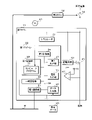
- FIG. 1 is a block diagram showing the main configuration of a power supply system 1 according to Embodiment 1.
- a power supply system 1 is mounted on a vehicle M.
- the power supply system 1 includes a first 1ECU11, a second 2ECU12, a second 3ECU13, a power switch 14, a DC power supply 15 and a load E1.
- ECU is an abbreviation for Electronic Control Unit.
- the power switch 14 is an FET, bipolar transistor, relay contact, or the like. FET is an abbreviation for Field Effect Transistor.
- the DC power supply 15 is, for example, a battery.
- the load E1 is an electric device. When load E1 is powered, load E1 operates. When the power supply to the load E1 stops, the load E1 stops operating.
- the first ECU 11 has a power supply switch F1.
- the power supply switch F1 is an N-channel FET. When the feed switch F1 is on, the resistance between the drain and source of the feed switch F1 is sufficiently small to allow current to flow through the drain and source. When the feed switch F1 is off, the resistance between the drain and source of the feed switch F1 is sufficiently large that no current flows through the drain and source.
- power lines and communication lines are indicated by thin solid lines and thick solid lines, respectively.
- 1ECU11, 2ECU12 and 3ECU13 are connected to the communication bus B.
- a drain of the power supply switch F1 of the first ECU11 is connected to one end of the power switch .
- the other end of the power switch 14 is connected to the positive electrode of the DC power supply 15 .
- a negative electrode of the DC power supply 15 is grounded.
- the source of the power supply switch F1 is connected to one end of the load E1.
- the other end of load E1 is grounded. Grounding is realized by connection to the body of the vehicle M, for example.
- the second 2ECU 12 switches the power switch 14 on or off.
- the first ECU 11 switches the power supply switch F1 on or off while the power switch 14 is on.
- the first ECU 11 turns on the power supply switch F1
- current flows from the positive terminal of the DC power supply 15 to the power switch 14, the power supply switch F1 and the load E1 in this order.
- power is supplied to the load E1, and the load E1 operates.
- the first ECU 11 controls power supply via the power switch 14 and the power supply switch F1 by switching the power supply switch F1 on or off.
- the 1ECU11 and the power supply switch F1 function as a control device and a first switch, respectively.
- the power switch 14 is arranged upstream of the power supply switch F1 in the current path of the current flowing through the power supply switch F1.
- Each of the 2ECU12 and the power switch 14 functions as a switching device and a second switch.
- a system including the first ECU 11, the second ECU 12, and the power switch 14 functions as a power supply control system Q.
- a power supply control system Q is included in the power supply system 1 .
- Vehicle data D1 is input to the first ECU11.
- the vehicle data D1 indicates detection values detected by sensors mounted on the vehicle M.
- FIG. An occupant of the vehicle M instructs an operation such as turning on the lamp, turning off the lamp, locking or unlocking the door, etc., by operating the operation unit.
- the vehicle data D1 indicates the action instructed by operating the operation unit.
- the first 1ECU11 transmits the vehicle data D1 to the second 3ECU13 via the communication bus B.
- An electrical device (not shown) is connected to the 3ECU 13.
- the second 3ECU13 when receiving the vehicle data D1 from the first 1ECU11, based on the received vehicle data D1, controls the operation of the electrical equipment.
- an energization failure may occur in which a current flows through the power supply switch F1 even though the power supply switch F1 has been instructed to be turned off.
- the resistance value between the drain and the source of the power supply switch F1 does not rise to a sufficiently high value when the power supply switch F1 is instructed to be turned off.
- the energization failure includes a short-circuit failure in which the drain and source of the power supply switch F1 remain short-circuited despite an instruction to turn off the power supply switch F1.
- the first ECU 11 detects the power failure.
- the 1ECU11 transmits the failure occurrence data indicating the occurrence of the energization failure to the 2ECU12 via the communication bus B.
- the 2ECU12 receives the failure occurrence data, the 2ECU12 alternately repeats switching the power switch 14 on and off.
- the period during which the power switch 14 is on is referred to as an on period.
- a period during which the power switch 14 is off is referred to as an off period.
- the ON period and OFF period are constant.
- the ON period is shorter than the OFF period.
- the ON period is, for example, one tenth of the OFF period.
- Power is supplied to the first ECU 11 from a connection node between the power switch 14 and the power supply switch F1.
- the first ECU 11 uses the power supplied from the connection node to transmit data or control power supply.
- the first 1ECU11 transmits the vehicle data D1 to the second 3ECU13 during the ON period.
- the load E1 is an inductive load, a resistive load, or the like.
- An inductive load has an inductor.
- An inductive load is, for example, a motor.
- a resistive load has only resistance.
- a resistive load is actuated by passing a current through the resistor.
- the 2ECU12 when the power switch 14 is switched from OFF to ON, transmits, via the communication bus B, failure notification data indicating the occurrence of an electrical failure in the power supply switch F1 to the 1ECU11.
- the on period is short.
- the load E1 is an inductive load
- the power switch 14 will turn off before the load E1 is actuated and the load E1 will remain deactivated.
- the load E1 is a resistive load
- the power switch 14 will turn off before the load E1 takes effect and the load E1 will stop operating.
- FIG. 2 is a block diagram showing the main configuration of the 1ECU 11.
- the first ECU 11 has a regulator 21, a first microcomputer (hereinafter referred to as a first microcomputer) 22, a drive circuit G1 and a comparator H1 in addition to the power supply switch F1.
- Comparator H1 has a plus end, a minus end and an output end.
- the drain of the power supply switch F1 is connected to one end of the power switch 14 as well as to the regulator 21 and the drive circuit G1.
- a gate of the power supply switch F1 is connected to the drive circuit G1.
- the drive circuit G1 is grounded.
- the source of the power supply switch F1 is connected to one end of the load E1 and also to the positive end of the comparator H1.
- a constant voltage Vc is applied to the negative end of the comparator H1.
- the reference potential of the constant voltage Vc is the ground potential.
- Output terminals of the driving circuit G1, the regulator 21 and the comparator H1 are connected to the first microcomputer 22 separately.
- the first microcomputer 22 is grounded.
- the DC power supply 15 supplies power to the driving circuit G1.
- the drive circuit G1 operates using power supplied from the DC power supply 15 .
- the regulator 21 steps down the output voltage of the DC power supply 15 to a constant voltage and applies the constant voltage generated by stepping down to the first microcomputer 22 .
- current flows from the positive electrode of the DC power supply 15 to the power switch 14, the regulator 21 and the first microcomputer 22 in this order.
- power is supplied to the first microcomputer 22 from the connection node between the power switch 14 and the power supply switch F1.
- the first microcomputer 22 operates using power supplied from the DC power supply 15 .
- regulator 21 When power switch 14 is on, regulator 21 applies a constant voltage to comparator H1. Current flows from the positive electrode of the DC power supply 15 to the power switch 14, the regulator 21 and the comparator H1 in this order, and power is supplied to the comparator H1.
- the comparator H1 operates using power supplied from the DC power supply 15 . Connection lines between the regulator 21 and the comparator H1 are omitted in order to avoid complication of the drawing. Comparator H1 is grounded. Note that the constant voltage Vc may be a voltage generated by the regulator 21 .
- the power supply switch F1 when the voltage of the gate whose reference potential is the potential of the source is equal to or higher than a certain voltage, the power supply switch F1 is on. For the feed switch F1, if the voltage at the gate whose reference potential is the potential of the source is less than a certain voltage, the feed switch F1 is off.
- the first microcomputer 22 has a first output section J1.
- the first output J1 is connected to the drive circuit G1.
- the first output section J1 outputs voltage to the driving circuit G1.
- the first output unit J1 switches the output voltage to a high level voltage or a low level voltage.
- the driving circuit G1 increases the voltage of the gate whose reference potential is the ground potential in the power supply switch F1.
- the voltage of the gate whose reference potential is the potential of the source rises to a voltage equal to or higher than the constant voltage.
- the power supply switch F1 is switched from off to on.
- the drive circuit G1 reduces the voltage of the gate whose reference potential is the ground potential in the power supply switch F1. As a result, in the power supply switch F1, the voltage of the gate whose reference potential is the potential of the source drops to a voltage less than the constant voltage. As a result, the power supply switch F1 is switched from on to off. As described above, the drive circuit G1 switches the power supply switch F1 on or off according to the output voltage of the first output section J1.
- the first microcomputer 22 further has a voltage input section T1.
- a voltage input T1 is connected to the output of the comparator H1.
- the source voltage the voltage of the source whose reference potential is the ground potential.
- a comparator H1 compares the source voltage of the power supply switch F1 with a constant voltage Vc.
- the comparator H1 outputs a high-level voltage to the voltage input section T1 when the source voltage of the power supply switch F1 is equal to or higher than the constant voltage Vc.
- the comparator H1 outputs a low level voltage to the voltage input section T1 when the source voltage of the power supply switch F1 is less than the constant voltage Vc.
- the constant voltage Vc exceeds zero V and is less than the power supply voltage across the DC power supply 15 .
- the source voltage of the power supply switch F1 substantially matches the power supply voltage of the DC power supply 15 . Therefore, when the power supply switch F1 is on, the output voltage of the comparator H1 is a high level voltage.
- the feed switch F1 is off, no current flows through the load E1. Therefore, the source voltage of the feed switch F1 is zero volts. Therefore, when the power supply switch F1 is off, the output voltage of the comparator H1 is a low level voltage.
- the first microcomputer 22 has a first communication section 31, a temporary storage section 32, a first storage section 33, a first control section 34, and a data input section U1, in addition to the first output section J1 and the voltage input section T1. While power is supplied to the first microcomputer 22 from the connection node between the power switch 14 and the power supply switch F1, the first communication unit 31, the temporary storage unit 32, the first storage unit 33, the first control unit 34, the first Power is supplied to 1 output J1, voltage input T1 and data input U1.
- the first communication unit 31, the temporary storage unit 32, the first storage unit 33, the first control unit 34, the first output unit J1, the voltage input unit T1, and the data input unit U1 are provided with the power switch 14 and the power supply switch, respectively. Power is supplied from the connection node between F1.
- the first communication section 31, the temporary storage section 32, the first storage section 33, the first control section 34, the first output section J1, the voltage input section T1 and the data input section U1 are connected to the first bus 35. As described above, the first output section J1 and the voltage input section T1 are connected to the driving circuit G1 and the comparator H1, respectively.
- the first communication section 31 is further connected to the communication bus B.
- the first output unit J1 switches the output voltage output to the drive circuit G1 to a high level voltage or a low level voltage according to an instruction from the first control unit 34 .
- the comparator H1 outputs a high level voltage or a low level voltage to the voltage input section T1.
- Vehicle data D1 is input to data input unit U1.
- the first communication unit 31 transmits the vehicle data D1 to the 3ECU 13 via the communication bus B according to the instruction of the first control unit 34.
- the first communication unit 31 transmits the failure occurrence data to the 2ECU 12 via the communication bus B according to the instruction of the first control unit 34 .
- the first communication unit 31 receives the failure notification data from the second ECU 12 via the communication bus B.
- the first control unit 34 writes data to the temporary storage unit 32.
- the data stored in the temporary storage unit 32 is deleted.
- Data stored in the temporary storage unit 32 is read by the first control unit 34 .
- the first storage unit 33 is, for example, a non-volatile memory.
- a computer program P1 is stored in the first storage unit 33 .
- the first control unit 34 has a processing element that executes processing, such as a CPU, and functions as a processing unit.
- the first controller 34 also functions as a first computer. By executing the computer program P1, the processing elements of the first control unit 34 concurrently execute transmission processing, power supply control processing, writing processing, and the like.
- the first control unit 34 executes a process for transmitting the vehicle data D1.
- the transmission process is different from the process for controlling power supply via the power supply switch F1.
- the transmission process corresponds to non-power supply control process.
- the first control unit 34 executes a process of controlling power supply to the load E1.
- the first control unit 34 writes into the temporary storage unit 32 failure data indicating that an electrical failure has occurred in the power supply switch F1.
- the computer program P1 may be provided to the first microcomputer 22 using a non-temporary storage medium A1 on which the computer program P1 is readable.
- the storage medium A1 is, for example, a portable memory. Examples of portable memory include CD-ROM, USB (Universal Serial Bus) memory, SD card, micro SD card, compact flash (registered trademark), and the like.
- the processing element of the first control unit 34 may read the computer program P1 from the storage medium A1 using a reading device (not shown).
- the read computer program P1 is stored in the first storage unit 33 .
- the computer program P1 may be provided to the first microcomputer 22 by a communication section (not shown) of the first microcomputer 22 communicating with an external device. In this case, the processing element of the first control unit 34 acquires the computer program P1 through the communication unit.
- the acquired computer program P1 is stored in the first storage unit 33 .
- the number of processing elements that the first control unit 34 has is not limited to one, and may be two or more.
- the plurality of processing elements may cooperatively execute transmission processing, power supply control processing, writing processing, and the like.
- FIG. 3 is a block diagram showing the main configuration of the 2ECU12.
- the second ECU 12 has a switching circuit 41 and a second microcomputer (hereinafter referred to as a second microcomputer) 42 .
- the second microcomputer 42 has a second output section 51 .
- the second output section 51 is connected to the switching circuit 41 .
- the second output section 51 outputs the voltage to the switching circuit 41 .
- the switching circuit 41 switches the power switch 14 from off to on.
- the switching circuit 41 switches the power switch 14 from ON to OFF.
- the second microcomputer 42 has a second communication section 52 , a second storage section 53 and a second control section 54 in addition to the second output section 51 .
- the second output section 51 , the second communication section 52 , the second storage section 53 and the second control section 54 are connected to the second bus 55 .
- the second communication section 52 is further connected to the communication bus B.
- the second output section 51 switches the output voltage output to the switching circuit 41 between the high level voltage and the low level voltage according to the instruction from the second control section 54 .
- the second communication unit 52 transmits failure notification data to the first communication unit 31 of the first ECU 11 via the communication bus B according to the instruction of the second control unit 54 .
- the second communication unit 52 receives failure occurrence data via the communication bus B from the first communication unit 31 of the first ECU 11 .
- the second storage unit 53 is, for example, a non-volatile memory.
- a computer program P2 is stored in the second storage unit 53 .
- the second control unit 54 has a processing element such as a CPU that executes processing.
- the second controller 54 also functions as a second computer.
- the processing element of the second control unit 54 executes the switch control process by executing the computer program P2. In the switch control process, the second control unit 54 executes a process of switching the power switch 14 on or off.
- the computer program P2 may be provided to the second microcomputer 42 using a non-temporary storage medium A2 that records the computer program P2 in a readable manner.
- the storage medium A2 is, for example, a portable memory. If the storage medium A2 is a portable memory, the processing element of the second controller 54 may read the computer program P2 from the storage medium A2 using a reading device (not shown). The read computer program P2 is stored in the second storage unit 53 .
- the computer program P2 may be provided to the second microcomputer 42 by the communication section (not shown) of the second microcomputer 42 communicating with an external device. In this case, the processing element of the second control unit 54 acquires the computer program P2 through the communication unit. The acquired computer program P2 is stored in the second storage unit 53 .
- the number of processing elements that the second control unit 54 has is not limited to one, and may be two or more.
- the plurality of processing elements may cooperatively execute switch control processing and the like.
- FIG. 4 is a flow chart showing the procedure of transmission processing of the first ECU 11.
- the first control unit 34 of the first ECU 11 first determines whether or not the vehicle data D1 is input to the data input unit U1 (step S1).
- the first control unit 34 determines that the vehicle data D1 has not been input (S1: NO)
- it executes step S1 again and waits until the vehicle data D1 is input to the data input unit U1.
- the first control unit 34 instructs the first communication unit 31 to transmit the vehicle data D1 to the 3ECU13 (step S2).
- step S2 the first control unit 34 ends the transmission process.
- the first control unit 34 executes the transmission process again. While power is being supplied to the first microcomputer 22, that is, while the power switch 14 is on, the first communication unit 31 receives the input vehicle data D1 each time the vehicle data D1 is input to the data input unit U1. D1 is sent to the 3ECU13.
- FIG. 5 is a flow chart showing the procedure of power supply control processing of the first ECU 11. As shown in FIG. When power is supplied to the first microcomputer 22 of the first ECU 11 by turning on the power switch 14, the first microcomputer 22 is activated. The first control unit 34 executes power supply control processing when the first microcomputer 22 is activated.
- the first control unit 34 first determines whether failure data is stored in the temporary storage unit 32 (step S11). When the first control unit 34 determines that the failure data is not stored in the temporary storage unit 32 (S11: NO), it determines whether or not to turn on the power supply switch F1 (step S12).
- step S12 for example, when an ON signal instructing to turn on the power supply switch F1 is input to a signal input unit (not shown), the first control unit 34 determines to turn on the power supply switch F1. .
- the first control section 34 determines not to turn on the power supply switch F1.
- step S13 determines whether to turn off the power supply switch F1 (step S13).
- step S13 for example, when an off signal instructing to turn off the power supply switch F1 is input to the signal input unit, the first control unit 34 determines to turn off the power supply switch F1. In this configuration, when the off signal is not input to the signal input section, the first control section 34 determines not to turn off the power supply switch F1.
- step S11 When the first control unit 34 determines not to turn off the power supply switch F1 (S13: NO), it executes step S11 again. The first control unit 34 waits until the failure data is written to the temporary storage unit 32 or until the timing to switch the power supply switch F1 on or off arrives.
- the first control unit 34 determines that failure data is stored in the temporary storage unit 32 (S11: YES), it ends the power supply control process. In this case, the first control unit 34 does not execute the power supply control process until the power supply to the first ECU 11 stops. The power supply to the first ECU 11 stops when the power switch 14 is turned off. When the first microcomputer 22 of the first ECU 11 is activated, the first control unit 34 executes the power supply control process again.
- the first control unit 34 determines to turn on the power supply switch F1 (S12: YES)
- the first control unit 34 instructs the first output unit J1 to switch the output voltage to the high level voltage, thereby turning on the power supply switch F1.
- the drive circuit G1 is instructed to switch to (step S14).
- the power supply switch F1 is turned on, power is supplied to the load E1 as described above.
- the first control unit 34 determines to turn off the power supply switch F1 (S13: YES)
- the first control unit 34 instructs the first output unit J1 to switch the output voltage to the low level voltage, thereby turning off the power supply switch F1.
- the drive circuit G1 is instructed to switch to (step S15).
- the power supply switch F1 is turned off, as described above, power supply to the load E1 is stopped.
- the feed switch F1 is off, the source voltage of the feed switch F1 is zero volts.
- step S15 the first control unit 34 determines whether or not an energization failure of the power supply switch F1 has occurred based on the output voltage of the comparator H1 (step S16).
- step S16 when the output voltage of the comparator H1 is a high level voltage, the first control unit 34 determines that an electrical failure has occurred.
- the output voltage of the comparator H1 is a low-level voltage, the first control unit 34 determines that no energization failure has occurred.
- the first control unit 34 determines that an electrical failure has occurred (S16: YES), it generates failure data (step S17) and writes the generated failure data to the temporary storage unit 32 (step S18). After executing step S18, the first control unit 34 instructs the first communication unit 31 to transmit the failure occurrence data to the second communication unit 52 of the second 2ECU 12 via the communication bus B (step S19). . After executing one of steps S14 and S19, or when it is determined that an electrical failure has not occurred (S16: NO), the first control unit 34 ends the power supply control process. In this case, the first control unit 34 executes the power supply control process again.
- the first control unit 34 of the first ECU 11 instructs the power supply switch F1 to be turned on or off while the power switch 14 is on.
- the drive circuit G1 turns the power supply switch on or off until the first control unit 34 detects the power failure.
- the first control unit 34 writes failure data to the temporary storage unit 32 and notifies the second ECU 12 of the occurrence of an electrical failure.
- failure data is stored in the temporary storage unit 32, the first control unit 34 stops executing the power supply control process until the power supply to the first ECU11 stops.
- FIG. 6 is a flow chart showing the procedure of the switch control process of the second ECU12.
- the second control unit 54 of the 2ECU12 determines whether the second communication unit 52 has received the failure occurrence data from the first communication unit 31 of the 1ECU11 (step S21).
- the second control unit 54 executes step S21 again, and the second communication unit 52 receives the failure occurrence data. wait until
- the second control unit 54 determines that the second communication unit 52 has received the failure occurrence data (S21: YES), by instructing the second output unit 51 to switch the output voltage to the low level voltage, The switching circuit 41 is caused to switch off the power switch 14 (step S22). As a result, power supply to the load E1 is stopped. When the power switch 14 is turned off, power supply to the first microcomputer 22, the drive circuit G1, the comparator H1, etc. of the first ECU 11 is stopped. When the power supply to the first microcomputer 22 stops, the first microcomputer 22 stops operating, and the failure data stored in the temporary storage section 32 of the first microcomputer 22 is erased.
- step S22 the second control unit 54 determines whether or not a certain off period has elapsed since the switching circuit 41 turned off the power switch 14 (step S23). When the second control unit 54 determines that the OFF period has not passed (S23: NO), it executes step S23 and waits until the OFF period passes.
- the second control unit 54 determines that the OFF period has elapsed (S23: YES)
- the second control unit 54 instructs the second output unit 51 to switch the output voltage to the high level voltage, thereby causing the switching circuit 41 to turn on the power switch 14. is switched on (step S24).
- the power switch 14 is turned on, power is supplied to the first microcomputer 22 of the first ECU 11, the drive circuit G1, the comparator H1, and the like.
- the first microcomputer 22 is activated. At this time, no failure data is stored in the temporary storage unit 32 of the first microcomputer 22 .
- the second control unit 54 instructs the second communication unit 52 to transmit failure notification data to the first communication unit 31 of the first ECU 11 (step S25). As a result, the first ECU 11 is notified of the occurrence of an electrical failure in the power supply switch F1.
- the second control unit 54 determines whether or not a certain ON period has elapsed since the power switch 14 was turned on (step S26). When the second control unit 54 determines that the ON period has not passed (S26: NO), it executes step S26 again and waits until the ON period passes.
- the first control unit 34 executes transmission processing. Therefore, when the vehicle data D1 is input to the data input unit U1 during the ON period, the first communication unit 31 transmits the vehicle data D1 input to the data input unit U1 to the 3ECU13.
- the second control unit 54 determines that the ON period has passed (S26: YES), it executes step S22 again.
- the switching circuit 41 alternately repeats switching on and off of the power switch 14 .
- the second control unit 54 alternately repeatedly turns on and off the power switch 14. instruct.
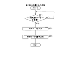
- FIG. 7 is a flow chart showing the procedure of the writing process of the 1ECU 11.
- the first control unit 34 executes writing processing.
- the first control unit 34 of the 1ECU11 determines whether the first communication unit 31 has received the failure notification data from the second communication unit 52 of the 2ECU12 (step S31).
- the first control unit 34 determines that the first communication unit 31 has not received the failure notification data (S31: NO)
- the first communication unit 31 executes step S31 again, and the first communication unit 31 receives the failure notification data. wait until
- the first control unit 34 When determining that the first communication unit 31 has received the failure notification data (S31: YES), the first control unit 34 generates failure data (step S32) and writes the generated failure data to the temporary storage unit 32. (Step S33). After executing step S33, the first control unit 34 ends the writing process.
- the first control unit 34 writes the failure data to the temporary storage unit 32.
- the second control unit 54 instructs the switching circuit 41 to turn on the power switch 14, and then causes the second communication unit 52 to transmit failure notification data.
- the first microcomputer 22 of the first ECU 11 is activated, and the first control unit 34 executes power supply control processing.
- the first control unit 34 causes the power switch 14 to control power supply immediately after the first microcomputer 22 is activated. End the process.
- FIG. 8 is a timing chart for explaining the operations of the 1ECU11 and the 2ECU12.
- FIG. 8 shows the state of the power switch 14, the state of the first communication unit 31 of the first ECU 11, the instruction of the power supply switch F1, and the transition of the source voltage of the power supply switch F1. Time is indicated on the horizontal axis of these transitions.
- Vb indicates the power supply voltage of the DC power supply 15 .
- the switching circuit 41 of the 2ECU 12 keeps the power switch 14 on before the energization failure is detected. While the switching circuit 41 keeps the power switch 14 on, in the first ECU 11, the first communication unit 31 transmits the vehicle data D1 each time the vehicle data D1 is input to the data input unit U1. While the switching circuit 41 keeps the power switch 14 on, the first control unit 34 instructs the drive circuit G1 to turn on or off the power supply switch F1.
- the drive circuit G1 follows an instruction from the first control unit 34 to switch the power supply switch F1 on or off. Therefore, the source voltage of the power supply switch F1 is the power supply voltage Vb of the DC power supply 15 while the first control unit 34 instructs to turn on the power supply switch F1.
- the power supply voltage Vb is equal to or higher than the constant voltage Vc.
- the source voltage of the power supply switch F1 is zero V while the first control unit 34 instructs to turn off the power supply switch F1. Zero V is less than a constant voltage Vc.
- the first control unit 34 determines that an energization failure of the power supply switch F1 has occurred. do. As a result, the first controller 34 detects an energization failure of the power supply switch F1.
- the switching circuit 41 of the 2ECU 12 switches the power switch 14 off.
- the first control unit 34 of the first ECU 11 terminates the power supply control process when detecting an electrical failure, and does not execute the power supply control process until the first microcomputer 22 of the first ECU 11 is restarted.
- the switching circuit 41 of the second 2ECU 12 alternately turns on and off the power switch 14 .
- the ON period and OFF period of the power switch 14 are constant. The ON period is shorter than the OFF period. Therefore, less power is supplied to the load E1 through the power switch 14 and the power supply switch F1 during the ON period.
- load E1 is an inductive load
- power switch 14 will turn off before load E1 is actuated.
- the operation of load E1 is substantially stopped. If the load E1 is a resistive load, the power switch 14 will turn off before the load E1 takes effect and the load E1 will stop operating.
- the first control unit 34 of the first ECU 11 can execute the transmission process because there is an ON period. Therefore, in the 1ECU 11, when the vehicle data D1 is input to the data input unit U1 during the ON period, the first communication unit 31 transmits the vehicle data D1.
- the switching circuit 41 switches the power switch 14 to ON
- the second communication unit 52 transmits failure notification data to the first communication unit 31 of the 1ECU11. Therefore, the first control unit 34 of the first ECU 11 terminates the power supply control process before instructing the power supply switch F1 to be turned on.
- the first ECU11 controls power supply to the load E1.
- the first ECU11 may control not only power supply to the load E1 but also power supply to other loads.
- Configurations other than those described later are the same as those of the first embodiment, so the same reference numerals as those of the first embodiment are given to the components that are common to the first embodiment, and the description thereof will be omitted.
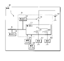
- FIG. 9 is a block diagram showing the main configuration of the power supply system 1 according to the second embodiment.
- the power supply system 1 according to the second embodiment is similarly equipped with the components of the power supply system 1 according to the first embodiment.
- the power supply system 1 in Embodiment 2 further includes a load E2.
- the load E2 is an electric device. Load E2 acts similarly to load E1.
- the first ECU11 has not only the power supply switch F1 but also the power supply switch F2.
- the power supply switch F2 is an N-channel FET. Feed switch F2 operates similarly to feed switch F1.
- the power supply switch F2 also functions as a first switch.
- power lines and communication lines are indicated by thin solid lines and thick solid lines, respectively.
- a drain of the power supply switch F2 is connected to one end of the power switch 14 .
- the source of feed switch F2 is connected to load E2.
- the other end of load E2 is grounded.
- the first ECU 11 switches the power supply switch F2 on or off while the power switch 14 is on.
- the first ECU 11 turns on the power supply switch F2
- current flows from the positive terminal of the DC power supply 15 to the power switch 14, the power supply switch F2 and the load E2 in this order.
- the load E2 operates.
- the first ECU 11 turns off the power supply switch F2
- current flow through the power switch 14 and the power supply switch F2 is stopped.
- power supply to the load E2 is stopped, and the load E2 stops operating.
- the current flowing through the power switch 14 is divided into two currents. Each of these currents flows through a feed switch F1, F2.
- the power switch 14 is arranged on the upstream side of the current path of the current flowing through the power supply switch F1, and arranged on the upstream side of the current path of the current flowing through the power supply switch F2.
- the first ECU 11 controls power supply through the power switch 14 and the power supply switch F1 by switching the power supply switch F1 on or off. As described above, the first ECU 11 controls power supply through the power switch 14 and the power supply switch F2 by switching the power supply switch F2 on or off.
- the first ECU 11 receives not only the vehicle data D1 but also the vehicle data D2.
- the vehicle data D2, like the vehicle data D1, indicates sensor detection values or operations.
- Two electric devices (not shown) are connected to the 3ECU13.
- the second 3ECU13 when receiving the vehicle data D1 from the first 1ECU11, based on the received vehicle data D1, controls the operation of one electrical equipment.
- the second 3ECU13 when receiving the vehicle data D2 from the first 1ECU11, based on the received vehicle data D2, controls the operation of the other electrical equipment.
- the energization failure of the power supply switch F2 includes the short-circuit failure of the power supply switch F2 as well as the energization failure of the power supply switch F1.
- the first ECU 11 detects the power supply failure of the power supply switch F1 or the power supply switch F2.
- the 1ECU11 transmits the failure occurrence data indicating the occurrence of the energization failure to the 2ECU12 via the communication bus B.
- the fault occurrence data indicates which of the power supply switches F1 and F2 has an energization fault.
- the 2ECU12 alternately repeats switching the power switch 14 on and off.
- the ON period differs depending on which of the power supply switches F1 and F2 has an energization failure.
- the ON period is long when the power supply switch F1 has an energization failure.
- the ON period is short when the power supply switch F2 has an energization failure.
- the vehicle data D1 and D2 are sent to the 3ECU13 during the ON period Send.
- the 1ECU11 transmits the vehicle data D2 to the 3ECU13 during the ON period.
- the first 1ECU11 does not transmit the vehicle data D1 to the second 3ECU13 during the ON period.
- the load E2 is an inductive load, a resistive load, or the like.
- the 2ECU12 when the power switch 14 is switched from OFF to ON, to the 1ECU11, via the communication bus B, the failure notification data indicating the occurrence of the power supply failure in the power supply switch F1 or the power supply switch F2.
- the failure notification data indicates which of the power supply switches F1 and F2 has an electrical failure.
- the load E2 is an inductive load.
- the power switch 14 is turned off before the load E2 is activated, and the load E2 remains deactivated.
- load E2 is a resistive load.
- the power switch 14 turns off before the effect of the load E2 appears, and the load E2 stops operating.
- the period from when the power switch 14 is turned on until the effect of the resistive load appears is referred to as the resistance period.
- a period from when the power switch 14 is turned on until the inductive load is activated is referred to as an induction period.
- the resistance period is usually longer than the induction period. Therefore, the ON period of the power supply switch connected to the resistive load can be set longer than the ON period of the power supply switch connected to the inductive load.
- each of the loads E1 and E2 is a resistive load and an inductive load.
- the ON period of the power supply switch F1 can be set longer than the ON period of the power supply switch F2.
- the 2ECU 12 transmits, via the communication bus B, failure notification data indicating the occurrence of an energization failure in the power supply switch F1 or the power supply switch F2 to the 1ECU 11.
- the failure notification data indicates which of the power supply switches F1 and F2 has an electrical failure.
- FIG. 10 is a block diagram showing the main configuration of the 1ECU 11. As shown in FIG.
- the 1ECU11 in the second embodiment similarly has the components of the 1ECU11 in the first embodiment.
- the first ECU11 in the second embodiment further has a power supply switch F2, a drive circuit G2 and a comparator H2.
- Comparator H2 has a plus end, a minus end and an output end.
- the drain of the power supply switch F2 is connected to one end of the power switch 14 and also to the drive circuit G2.
- a gate of the power supply switch F2 is connected to the drive circuit G2.
- the drive circuit G2 is grounded.
- the source of the power supply switch F2 is connected to one end of the load E2 and also to the positive end of the comparator H2.
- a constant voltage Vc is applied to the negative terminal of the comparator H2.
- Output terminals of the driving circuit G2 and the comparator H2 are connected to the first microcomputer 22 separately.
- Power is supplied to the drive circuit G2 and the comparator H2, respectively, in the same manner as the drive circuit G1 and the comparator H1.
- the power supply switch F2 is configured similarly to the power supply switch F1.
- FIG. 11 is a block diagram showing the main configuration of the first microcomputer 22.
- the first microcomputer 22 according to the second embodiment has the same components as the first microcomputer 22 according to the first embodiment.
- the first microcomputer 22 in the second embodiment further has a first output section J2, a voltage input section T2 and a data input section U2.
- the first output section J2 is connected to the driving circuit G2.
- the first output section J2 and the drive circuit G2 act similarly to the first output section J1 and the drive circuit G1, respectively. Therefore, when the first output section J2 switches the output voltage from the low level voltage to the high level voltage, the drive circuit G2 switches the power supply switch F2 from off to on. When the first output section J2 switches the output voltage from the high level voltage to the low level voltage, the drive circuit G2 switches the power supply switch F2 from on to off.
- the voltage input section T2 is connected to the output terminal of the comparator H2.
- the voltage of the source whose reference potential is the ground potential is referred to as the source voltage.
- Comparator H2 operates in the same manner as comparator H1. Therefore, the comparator H2 outputs a high level voltage to the voltage input section T2 when the source voltage of the power supply switch F2 is equal to or higher than the constant voltage Vc.
- the comparator H2 outputs a low level voltage to the voltage input section T2 when the source voltage of the power supply switch F2 is less than the constant voltage Vc.
- the source voltage of the power supply switch F2 substantially matches the power supply voltage of the DC power supply 15 . Therefore, when the power supply switch F2 is on, the output voltage of the comparator H2 is a high level voltage.
- the output voltage of the comparator H2 is a high level voltage.
- the source voltage of the feed switch F2 is zero volts. Therefore, when the power supply switch F2 is off, the output voltage of the comparator H2 is a low level voltage.
- first output section J2 the voltage input section T2 and the data input section U2 are connected to the first bus 35.
- the first communication section 31, the temporary storage section 32, the first storage section 33, the first control section 34, the first output sections J1 and J2, the voltage input sections T1 and T2, and the data input sections U1 and U2 each have Power is supplied from a connection node between the power switch 14 and the power supply switch F1.
- the first output section J2 switches the output voltage output to the driving circuit G1 between the high level voltage and the low level voltage according to the instruction of the first control section 34.
- the comparator H2 outputs a high level voltage or a low level voltage to the voltage input section T2.
- Vehicle data D2 is input to data input unit U2.
- the first communication unit 31 transmits not only the vehicle data D1 but also the vehicle data D2 to the 3ECU13 via the communication bus B according to the instruction of the first control unit 34.
- the processing elements of the first control unit 34 concurrently execute transmission processing of the vehicle data D1 and D2, power supply control processing of the loads E1 and E2, write processing, and execution stop processing.
- the first control unit 34 executes the process for transmitting the vehicle data D1 and D2.
- Transmission processing of vehicle data D1 and D2 is different from processing related to control of power supply via power supply switches F1 and F2. Transmission processing for each of the vehicle data D1 and D2 corresponds to non-power supply control processing.
- the first control unit 34 executes a process for controlling power supply to each of the loads E1 and E2.
- the first control unit 34 writes, in the temporary storage unit 32, failure data indicating that an electrical failure has occurred in the power supply switch F1 or the power supply switch F2.
- the fault data indicates which of the power supply switches F1 and F2 has an energization fault.
- the first control unit 34 stops one execution during the transmission processing of the vehicle data D1, D2.
- the number of processing elements that the first control unit 34 has is not limited to one, and may be two or more.
- the plurality of first control units 34 perform transmission processing of vehicle data D1 and D2, power supply control processing of loads E1 and E2, write processing, execution stop processing, and the like. may be performed jointly.
- the first control unit 34 of the first ECU 11 executes the transmission processing of the vehicle data D1 in the same manner as in the first embodiment.
- the transmission process of the vehicle data D2 is the same as the transmission process of the vehicle data D1.
- the transmission process of the vehicle data D2 can be explained by replacing the data input part U1 and the vehicle data D1 with the data input part U2 and the vehicle data D2.
- FIG. 12 is a flow chart showing the procedure of power supply control processing for the load E1.
- the first control unit 34 executes power supply control processing when the first microcomputer 22 is activated.
- step S11 of the power supply control process for the load E1 it is determined whether or not the temporary storage unit 32 stores failure data indicating the power supply switch F1 or the power supply switch F2.
- step S12 it executes step S12.
- the first control unit 34 determines that the failure data is stored in the temporary storage unit 32 (S11: YES), by instructing the first output unit J1 to switch the output voltage to the low level voltage, The drive circuit G1 is instructed to turn off the power supply switch F1 (step S41).
- the failure data stored in the temporary storage unit 32 indicates the power supply switch F2 and the power supply switch F1 is on
- the drive circuit G1 switches the power supply switch F1 from on to off.
- the first control unit 34 ends the power supply control process. In this case, the first control unit 34 does not execute the power supply control process for the load E1 until the power supply to the first ECU11 is stopped.
- the first control unit 34 generates failure data indicating the power supply switch F1.
- the first control unit 34 instructs the first communication unit 31 to transmit failure occurrence data indicating the power supply switch F1 to the second communication unit 52 of the 2ECU 12 via the communication bus B.
- the first control unit 34 executes the power supply control process for the load E2 in the same manner as the power supply control process for the load E1.
- the load E1 the power supply switches F1 and F2, the first output section J1, the drive circuit G1, and the comparator H1 are respectively connected to the load E2, the power supply switches F2 and F1, the first output section J2, the drive Replace with circuit G2 and comparator H2. Accordingly, the power supply control process for the load E2 can be explained. Therefore, in the power supply control process for the load E2, the first control unit 34 writes failure data indicating the power supply switch F2 into the temporary storage unit 32. FIG. Further, the first control unit 34 instructs the first communication unit 31 to transmit failure occurrence data indicating the power supply switch F2 to the second communication unit 52 of the 2ECU 12 via the communication bus B.
- step S16 of the power supply control process for the load E1 the first control unit 34 determines whether or not an energization failure has occurred in the power supply switch F1. In step S16 of the power supply control process for the load E2, the first control unit 34 determines whether or not an energization failure has occurred in the power supply switch F2. When the first control unit 34 determines that one of the power supply switches F1 and F2 has an electrical failure, it instructs the first communication unit 31 to transmit failure occurrence data indicating the power supply switch F1 or the power supply switch F2. is transmitted to the second communication unit 52 of the second ECU 12.
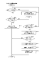
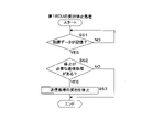
- FIG. 13 is a flow chart showing the procedure of the execution stop processing of the first ECU11.
- the first control unit 34 executes execution stop processing.
- the first control unit 34 of the first ECU 11 first determines whether or not the temporary storage unit 32 stores failure data indicating the power supply switch F1 or the power supply switch F2 (step S51).
- the first control unit 34 executes step S51 again and waits until the failure data is stored in the temporary storage unit 32. .
- the first control unit 34 determines whether or not the vehicle data D1 and D2 includes transmission processing that needs to be stopped (step S52). .
- FIG. 14 is a chart showing the relationship between a failed power switch and a transmission process that needs to be stopped. As shown in FIG. 14, when there is an energization failure of the power supply switch F1, there is no transmission process that needs to be stopped. If there is an energization failure of the power supply switch F2, it is necessary to stop the transmission process of the vehicle data D1.
- step S52 shown in FIG. 13 when the failure data stored in the temporary storage section 32 indicates the power supply switch F1, the first control section 34 determines that there is no transmission process that needs to be stopped. When the failure data stored in the temporary storage unit 32 indicates the power supply switch F2, the first control unit 34 determines that there is transmission processing that needs to be stopped.
- the first control unit 34 determines that there is a transmission process that needs to be stopped (S52: YES), it stops the transmission process that needs to be stopped, that is, the transmission process of the vehicle data D1 (step S53). If the first control unit 34 determines that there is no transmission process that needs to be stopped (S52: NO), or after executing step S53, it ends the execution stop process. As described above, when the failure data indicating the power supply switch F2 is stored in the temporary storage unit 32, the execution of the transmission process of the vehicle data D1 is stopped.
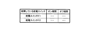
- the switch control process in the second embodiment is the same as the switch control process in the first embodiment. Therefore, when the second communication unit 52 receives the failure occurrence data from the first communication unit 31 of the 1ECU11, the switching circuit 41 of the 2ECU12 alternately turns on and off the power switch 14. As described above, the ON period differs depending on which of the power supply switches F1 and F2 has an energization failure. The off period also differs depending on which of the power supply switches F1 and F2 has an energization failure.
- the second storage unit 53 stores a period table indicating the ON period and the OFF period corresponding to the failed power supply switch.
- FIG. 15 is a chart showing the contents of the period table.
- the period table shows the ON period and OFF period corresponding to the power supply switch F1 and the ON period and OFF period corresponding to the power supply switch F2.
- the ON period of the power supply switch F1 is longer than the ON period of the power supply switch F2.
- the OFF period of the power supply switch F1 is shorter than the OFF period of the power supply switch F2.
- the total ON period and OFF period of the feed switch F1 is the same as the total ON period and OFF period of the feed switch F2. For each of the power supply switches F1 and F2, the ON period is shorter than the OFF period.
- step S21 of the switch control process in the second embodiment the second communication unit 52 of the second control unit 54 receives failure occurrence data indicating the power supply switch F1 or the power supply switch F2 from the first communication unit 31 of the first ECU 11. Determine whether or not When the failure occurrence data received by the second communication unit 52 indicates the power supply switch F1, the ON period and OFF period of the power supply switch F1 are used in the period table. When the failure occurrence data received by the second communication unit 52 indicates the power supply switch F2, the ON period and OFF period of the power supply switch F2 are used in the period table.
- the second control unit 54 instructs the second communication unit 52 to transmit the failure notification data indicating the power supply switch F1. It is made to transmit to the first communication unit 31 of the first ECU11.
- the failure occurrence data received by the second communication unit 52 indicates the power supply switch F2
- the second control unit 54 instructs the second communication unit 52 to transmit the failure notification data indicating the power supply switch F2. It is made to transmit to the first communication unit 31 of the first ECU11.
- the switching circuit 41 alternately turns on and off the power switch 14. repeat.
- the ON period and the OFF period differ depending on which power supply switch among the power supply switches F1 and F2 has an energization failure.
- step S31 the first control unit 34 of the 1ECU11, the first communication unit 31, from the second communication unit 52 of the 2ECU12, whether or not received failure notification data indicating the power supply switch F1 or the power supply switch F2. judge.
- step S32 failure data indicating the power supply switch F1 is generated.
- step S ⁇ b>33 failure data indicating the power supply switch F ⁇ b>1 is written to the temporary storage unit 32 .
- step S32 failure data indicating the power supply switch F2 is generated.
- step S ⁇ b>33 failure data indicating the power supply switch F ⁇ b>2 is written to the temporary storage unit 32 .
- the first communication unit 31 receives the failure notification data immediately after the power switch 14 is turned on. Immediately after, the power supply control process for the loads E1 and E2 is terminated. When the failure notification data received by the first communication unit 31 indicates the power supply switch F2, execution of the transmission process of the vehicle data D1 is stopped. When the failure notification data received by the first communication unit 31 indicates the power supply switch F1, transmission processing of the vehicle data D1 and D2 is executed.
- FIG. 16 is a timing chart for explaining the operations of the 1ECU11 and the 2ECU12. 16, the state of the power switch 14, the state of the first communication unit 31 of the first ECU 11, the instruction of the power supply switch F1, the source voltage of the power supply switch F1, the instruction of the power supply switch F2, and the transition of the source voltage of the power supply switch F2. It is shown. Time is indicated on the horizontal axis of these transitions.
- Fig. 16 shows the operation when an energization failure of the power supply switch F1 occurs.
- the switching circuit 41 of the second ECU 12 keeps the power switch 14 on before the power supply failure of the power supply switch F1 or the power supply switch F2 is detected. While the switching circuit 41 keeps the power switch 14 on, in the first ECU 11, the first communication unit 31 transmits the vehicle data D1 each time the vehicle data D1 is input to the data input unit U1. Each time the vehicle data D2 is input to the data input unit U2, the first communication unit 31 transmits the vehicle data D2.
- the first control unit 34 instructs the drive circuit G1 to turn on or off the power supply switch F1. Furthermore, the first control unit 34 instructs the drive circuit G2 to turn on or off the power supply switch F2.
- the driving circuits G1 and G2 follow instructions from the first control unit 34 to switch the power supply switches F1 and F2 on or off. Therefore, the source voltage of the power supply switch F1 is the power supply voltage Vb of the DC power supply 15 while the power supply switch F1 is on.
- the source voltage of the power supply switch F2 is the power supply voltage Vb of the DC power supply 15 while the power supply switch F2 is on. While the feed switch F1 is indicated off, the source voltage of the feed switch F1 is zero volts. While the feed switch F2 is indicated to be OFF, the source voltage of the feed switch F2 is zero volts.
- the power supply voltage Vb is equal to or higher than the constant voltage Vc. Zero V is less than a constant voltage Vc.
- the first control unit 34 determines that an energization failure of the power supply switch F1 has occurred. do. As a result, the first controller 34 detects an energization failure of the power supply switch F1.
- the first control unit 34 of the first ECU 11 detects an energization failure of the power supply switch F1
- the first control unit 34 instructs the drive circuit G2 to turn off the power supply switch F2.
- the switching circuit 41 of the second ECU 12 switches the power switch 14 off.
- the first control unit 34 of the first ECU 11 detects an energization failure of the power supply switch F1 or the power supply switch F2
- the switching circuit 41 of the second 2ECU 12 alternately turns on and off the power switch 14 . Even if an electrical failure occurs, the first control unit 34 of the first ECU 11 can execute the transmission process of the vehicle data D1 and D2 because there is an ON period. Therefore, in the 1ECU 11, when the vehicle data D1 is input to the data input unit U1 during the ON period, the first communication unit 31 transmits the vehicle data D1. Similarly, when the vehicle data D2 is input to the data input unit U2 during the ON period, the first communication unit 31 transmits the vehicle data D2.
- the second communication unit 52 transmits failure notification data indicating the power supply switch F1 to the first communication unit 31 of the first ECU 11. Therefore, the first control unit 34 of the first ECU 11 terminates the power supply control process for the loads E1 and E2 before instructing to turn on the power supply switches F1 and F2.
- FIG. 17 is another timing chart for explaining the operations of the 1ECU11 and the 2ECU12. 17 shows the state of the power switch 14, the state of the first communication unit 31 of the first ECU 11, the instruction of the power supply switch F1, the source voltage of the power supply switch F1, the instruction of the power supply switch F2, and the transition of the source voltage of the power supply switch F2. It is shown. Time is indicated on the horizontal axis of these transitions.
- Fig. 17 shows the operation when an energization failure of the power supply switch F2 occurs.
- the operation before detection of an energization failure of the power supply switch F1 or the power supply switch F2 is as described above. If the source voltage of the power supply switch F1 is equal to or higher than the constant voltage Vc despite the instruction to turn off the power supply switch F2, the first control unit 34 determines that an energization failure of the power supply switch F2 has occurred. do. As a result, the first control unit 34 detects an energization failure of the power supply switch F2.
- the first control unit 34 of the first ECU 11 detects an energization failure of the power supply switch F2
- the first control unit 34 instructs the drive circuit G1 to turn off the power supply switch F1.
- the switching circuit 41 of the second ECU 12 switches the power switch 14 off.
- the first control unit 34 of the first ECU 11 detects an energization failure of the power supply switch F1 or the power supply switch F2, it terminates the power supply control process for the loads E1 and E2, and continues until the first microcomputer 22 of the first ECU 11 is restarted. Power supply control processing for the loads E1 and E2 is not executed.
- the first control unit 34 of the first ECU 11 stops executing the transmission process of the vehicle data D1 when detecting an energization failure of the power supply switch F2.
- the switching circuit 41 of the second 2ECU 12 After the first control unit 34 detects an electrical failure, the switching circuit 41 of the second 2ECU 12 alternately turns on and off the power switch 14 . Even if an electrical failure occurs, the ON period exists, so the first control unit 34 of the first ECU 11 can execute the transmission process of the vehicle data D2. Therefore, in the 1ECU 11, when the vehicle data D2 is input to the data input unit U2 during the ON period, the first communication unit 31 transmits the vehicle data D2.
- the second communication unit 52 transmits failure notification data indicating the power supply switch F2 to the first communication unit 31 of the 1ECU11. Therefore, the first control unit 34 of the first ECU 11 terminates the power supply control process for the loads E1 and E2 before instructing to turn on the power supply switches F1 and F2. Further, the first control unit 34 stops executing the transmission process of the vehicle data D1 before the first communication unit 31 transmits the vehicle data D1.
- the ON period of the power switch 14 is short, so transmission of the vehicle data D1 is stopped and transmission of the vehicle data D2 is executed.
- the first control unit 34 of the first ECU 11 performs transmission processing (non-power feeding control processing) of the vehicle data D1 and D2 before an energization failure occurs in one of the two power feeding switches F1 and F2. Run.
- the first control unit 34 determines that one of the two power supply switches F1 and F2 has a power supply failure, the power supply switch in which the power supply failure has occurred during the transmission process of the vehicle data D1 and D2.
- the number of non-power supply control processes is not limited to two, and may be three or more.
- the number of non-power supply control processes executed by the first control unit 34 when an energization failure of the power supply switch F1 is detected is equal to the number of non-power supply control processes executed by the first control unit 34 when an energization failure of the power supply switch F2 is detected. If it is different from the number of control processes, there is no problem.
- the first control unit 34 may perform the same number of non-power supply control processes when it determines that one of the two power supply switches F1 and F2 has an energization failure.
- the total of the ON period and the OFF period when the power failure of the power supply switch F1 occurs may be different from the total of the ON period and the OFF period when the power failure of the power supply switch F2 occurs.
- the OFF period may be constant regardless of which of the two power supply switches F1 and F2 has a power failure.
- the number of power supply switches that the first ECU 11 has is not limited to two, and may be three or more. In this case, it is determined whether or not an energization failure has occurred for each of the plurality of power supply switches.
- the switching circuit 41 of the second ECU 12 alternately turns on and off the power switch 14. Repeat.
- the ON period varies depending on the power supply switch in which the energization failure has occurred.
- the first control unit 34 may perform the same or different number of non-power feeding control processes when determining that one of the plurality of power feeding switches has an energization failure. good.
- the method of determining whether or not an energization failure of the power supply switch has occurred is not limited to a method based on the source voltage of the power supply switch. An output current being output from the source of the power supply switch may be detected. The first control unit 34 of the first ECU 11 determines that an energization failure of the power supply switch has occurred when current is output from the source of the power supply switch despite the instruction to turn off the power supply switch. do.
- Non-power feeding control processing which is different from power feeding control, is not limited to data transmission processing, and may be, for example, determination processing.
- the power switch 14 may be arranged inside the second ECU 12 .
- the number of the 3ECU13 connected to the communication bus B is not limited to one, it may be two or more.
- the second 3ECU13 to which the vehicle data D1 is transmitted may be different from the second 3ECU13 to which the vehicle data D2 is transmitted.
- Each of the power supply switches F1 and F2 is not limited to an N-channel FET, and may be a P-channel FET, a bipolar transistor, a relay contact, or the like.
- 1 power supply system 11 1st ECU (control device) 12 2nd ECU (switching device) 13 3rd ECU 14 power switch (second switch) 15 DC power supply 21 regulator 22 first microcomputer 31 first communication unit 32 temporary storage unit 33 first storage unit 34 first control unit (processing unit, first computer) 35 first bus 41 switching circuit 42 second microcomputer 51 second output unit 52 second communication unit 53 second storage unit 54 second control unit (second computer) 55 Second bus A1, A2 Storage medium B Communication bus D1, D2 Vehicle data E1, E2 Load F1, F2 Power supply switch (first switch) G1, G2 drive circuit H1, H2 comparator J1, J2 first output unit M vehicle P1, P2 computer program Q power supply control system T1, T2 voltage input unit U1, U2 data input unit
Landscapes
- Engineering & Computer Science (AREA)
- Power Engineering (AREA)
- Mechanical Engineering (AREA)
- Direct Current Feeding And Distribution (AREA)
- Protection Of Static Devices (AREA)
Priority Applications (2)
| Application Number | Priority Date | Filing Date | Title |
|---|---|---|---|
| US18/555,447 US12407162B2 (en) | 2021-04-15 | 2022-03-25 | Power supply control system and processing method |
| CN202280024859.9A CN117121320A (zh) | 2021-04-15 | 2022-03-25 | 供电控制系统和处理方法 |
Applications Claiming Priority (2)
| Application Number | Priority Date | Filing Date | Title |
|---|---|---|---|
| JP2021-069075 | 2021-04-15 | ||
| JP2021069075A JP7552489B2 (ja) | 2021-04-15 | 2021-04-15 | 給電制御システム及び処理方法 |
Publications (1)
| Publication Number | Publication Date |
|---|---|
| WO2022220055A1 true WO2022220055A1 (ja) | 2022-10-20 |
Family
ID=83640594
Family Applications (1)
| Application Number | Title | Priority Date | Filing Date |
|---|---|---|---|
| PCT/JP2022/014244 Ceased WO2022220055A1 (ja) | 2021-04-15 | 2022-03-25 | 給電制御システム及び処理方法 |
Country Status (4)
| Country | Link |
|---|---|
| US (1) | US12407162B2 (https=) |
| JP (1) | JP7552489B2 (https=) |
| CN (1) | CN117121320A (https=) |
| WO (1) | WO2022220055A1 (https=) |
Families Citing this family (1)
| Publication number | Priority date | Publication date | Assignee | Title |
|---|---|---|---|---|
| JP2023169933A (ja) * | 2022-05-18 | 2023-12-01 | トヨタ自動車株式会社 | 制御装置、通信制御方法、通信制御プログラム |
Citations (4)
| Publication number | Priority date | Publication date | Assignee | Title |
|---|---|---|---|---|
| JP2004201410A (ja) * | 2002-12-18 | 2004-07-15 | Denso Corp | 誘導性負荷駆動装置及びその異常検出方法 |
| JP2019521323A (ja) * | 2016-12-12 | 2019-07-25 | エルジー・ケム・リミテッド | 常時電源供給のための並列回路を用いてバッテリーのリレーの故障を診断する装置及び方法 |
| JP2020005344A (ja) * | 2018-06-25 | 2020-01-09 | 株式会社オートネットワーク技術研究所 | 給電制御装置 |
| JP2020061827A (ja) * | 2018-10-05 | 2020-04-16 | 株式会社デンソー | 電子制御装置 |
Family Cites Families (16)
| Publication number | Priority date | Publication date | Assignee | Title |
|---|---|---|---|---|
| DE10325363A1 (de) * | 2003-05-23 | 2005-01-13 | Pilz Gmbh & Co. | Sicherheitsschaltgerät zum fehlersicheren Abschalten eines elektrischen Verbrauchers sowie entsprechendes Verfahren |
| JP4529666B2 (ja) * | 2004-03-03 | 2010-08-25 | 株式会社デンソー | 負荷駆動装置及び負荷駆動制御方法 |
| WO2006016400A1 (ja) * | 2004-08-10 | 2006-02-16 | Mitsubishi Denki Kabushiki Kaisha | 直流電圧駆動型マグネットコンタクタの駆動回路および電力変換装置 |
| JP4736545B2 (ja) * | 2005-06-02 | 2011-07-27 | 株式会社豊田自動織機 | スイッチング素子の過電流保護装置 |
| US20080247108A1 (en) * | 2007-04-03 | 2008-10-09 | Denso Corporation | Load drive device |
| JP5265931B2 (ja) * | 2008-01-16 | 2013-08-14 | 矢崎総業株式会社 | 電力供給装置 |
| JP5184947B2 (ja) * | 2008-04-09 | 2013-04-17 | 株式会社東海理化電機製作所 | 短絡保護回路及び短絡保護方法 |
| US8390974B2 (en) * | 2010-08-18 | 2013-03-05 | Snap-On Incorporated | Overvoltage and overcurrent protection scheme |
| US9678139B2 (en) * | 2011-12-22 | 2017-06-13 | Continental Automotive Systems, Inc. | Method and apparatus for high side transistor protection |
| DE112012007241B4 (de) * | 2012-12-21 | 2022-06-02 | Mitsubishi Electric Corp. | Ansteuerschutzschaltung, Halbleitermodul und Kraftfahrzeug |
| JP5709964B1 (ja) * | 2013-10-28 | 2015-04-30 | 三菱電機株式会社 | 内燃機関点火装置 |
| JP2015104305A (ja) * | 2013-11-28 | 2015-06-04 | 株式会社デンソー | スイッチング電源装置および電子制御装置 |
| JP6436025B2 (ja) | 2015-09-14 | 2018-12-12 | 株式会社オートネットワーク技術研究所 | 給電制御装置、通信システム及び給電制御方法 |
| JP7159565B2 (ja) | 2018-02-07 | 2022-10-25 | 株式会社オートネットワーク技術研究所 | 給電制御装置、給電制御方法及びコンピュータプログラム |
| WO2020139787A1 (en) * | 2018-12-28 | 2020-07-02 | Continental Automotive Systems, Inc. | Input voltage limiter for a microcontroller |
| JP7238703B2 (ja) * | 2019-08-30 | 2023-03-14 | 株式会社オートネットワーク技術研究所 | 駆動装置 |
-
2021
- 2021-04-15 JP JP2021069075A patent/JP7552489B2/ja active Active
-
2022
- 2022-03-25 US US18/555,447 patent/US12407162B2/en active Active
- 2022-03-25 CN CN202280024859.9A patent/CN117121320A/zh active Pending
- 2022-03-25 WO PCT/JP2022/014244 patent/WO2022220055A1/ja not_active Ceased
Patent Citations (4)
| Publication number | Priority date | Publication date | Assignee | Title |
|---|---|---|---|---|
| JP2004201410A (ja) * | 2002-12-18 | 2004-07-15 | Denso Corp | 誘導性負荷駆動装置及びその異常検出方法 |
| JP2019521323A (ja) * | 2016-12-12 | 2019-07-25 | エルジー・ケム・リミテッド | 常時電源供給のための並列回路を用いてバッテリーのリレーの故障を診断する装置及び方法 |
| JP2020005344A (ja) * | 2018-06-25 | 2020-01-09 | 株式会社オートネットワーク技術研究所 | 給電制御装置 |
| JP2020061827A (ja) * | 2018-10-05 | 2020-04-16 | 株式会社デンソー | 電子制御装置 |
Also Published As
| Publication number | Publication date |
|---|---|
| US12407162B2 (en) | 2025-09-02 |
| JP2022163927A (ja) | 2022-10-27 |
| JP7552489B2 (ja) | 2024-09-18 |
| CN117121320A (zh) | 2023-11-24 |
| US20240204507A1 (en) | 2024-06-20 |
Similar Documents
| Publication | Publication Date | Title |
|---|---|---|
| CN110884558B (zh) | 用于向车辆中的eps供应电力的控制装置和方法 | |
| EP1530795A2 (en) | Hold-up power supply for flash memory | |
| WO2020137506A1 (ja) | 通電制御装置 | |
| US20250044370A1 (en) | Power supply control device and failure detection method | |
| CN108701989A (zh) | 供电控制装置 | |
| WO2022220055A1 (ja) | 給電制御システム及び処理方法 | |
| JP2017225045A (ja) | 給電制御装置 | |
| JP2007010563A (ja) | 誘導性負荷の異常検出装置 | |
| US11233938B2 (en) | Power management apparatus and power management system | |
| CN107408828B (zh) | 控制车辆的电路的电力供应的包含电池和相关组件的设备 | |
| JP7504737B2 (ja) | 半導体回路、及び半導体回路の故障判定方法 | |
| JP7782657B2 (ja) | 給電制御装置及び給電制御方法 | |
| JP7340477B2 (ja) | 半導体装置及び電源システム | |
| CN117678135A (zh) | 电力供给装置 | |
| WO2022249728A1 (ja) | 給電制御装置及び給電制御方法 | |
| WO2022249719A1 (ja) | 給電制御装置及び給電制御方法 | |
| US20220216863A1 (en) | Semiconductor device | |
| CN114640145B (zh) | 用于车辆的功率装置 | |
| JP2019160487A (ja) | 電源供給回路 | |
| JP2024092543A (ja) | 車載装置、制御方法及びプログラム | |
| CN118827267A (zh) | 具有负载点电源的电源电路、负载点电源及其操作方法 | |
| CN117461132A (zh) | 半导体装置及电压施加方法 | |
| JP2025086240A (ja) | 車載装置、判定方法、及びコンピュータプログラム | |
| CN121180128A (zh) | 电子控制单元ecu以及故障信息传输电路 | |
| JP2021027740A (ja) | 電源装置 |
Legal Events
| Date | Code | Title | Description |
|---|---|---|---|
| 121 | Ep: the epo has been informed by wipo that ep was designated in this application |
Ref document number: 22787980 Country of ref document: EP Kind code of ref document: A1 |
|
| WWE | Wipo information: entry into national phase |
Ref document number: 18555447 Country of ref document: US |
|
| NENP | Non-entry into the national phase |
Ref country code: DE |
|
| 122 | Ep: pct application non-entry in european phase |
Ref document number: 22787980 Country of ref document: EP Kind code of ref document: A1 |
|
| WWG | Wipo information: grant in national office |
Ref document number: 18555447 Country of ref document: US |