WO2022215499A1 - ホログラフィー装置及び細胞の評価方法 - Google Patents
ホログラフィー装置及び細胞の評価方法 Download PDFInfo
- Publication number
- WO2022215499A1 WO2022215499A1 PCT/JP2022/012806 JP2022012806W WO2022215499A1 WO 2022215499 A1 WO2022215499 A1 WO 2022215499A1 JP 2022012806 W JP2022012806 W JP 2022012806W WO 2022215499 A1 WO2022215499 A1 WO 2022215499A1
- Authority
- WO
- WIPO (PCT)
- Prior art keywords
- image
- light
- interference
- phase
- object light
- Prior art date
- Legal status (The legal status is an assumption and is not a legal conclusion. Google has not performed a legal analysis and makes no representation as to the accuracy of the status listed.)
- Ceased
Links
Images


Classifications
-
- G—PHYSICS
- G03—PHOTOGRAPHY; CINEMATOGRAPHY; ANALOGOUS TECHNIQUES USING WAVES OTHER THAN OPTICAL WAVES; ELECTROGRAPHY; HOLOGRAPHY
- G03H—HOLOGRAPHIC PROCESSES OR APPARATUS
- G03H1/00—Holographic processes or apparatus using light, infrared or ultraviolet waves for obtaining holograms or for obtaining an image from them; Details peculiar thereto
- G03H1/22—Processes or apparatus for obtaining an optical image from holograms
-
- G—PHYSICS
- G01—MEASURING; TESTING
- G01N—INVESTIGATING OR ANALYSING MATERIALS BY DETERMINING THEIR CHEMICAL OR PHYSICAL PROPERTIES
- G01N21/00—Investigating or analysing materials by the use of optical means, i.e. using sub-millimetre waves, infrared, visible or ultraviolet light
- G01N21/17—Systems in which incident light is modified in accordance with the properties of the material investigated
- G01N21/41—Refractivity; Phase-affecting properties, e.g. optical path length
- G01N21/45—Refractivity; Phase-affecting properties, e.g. optical path length using interferometric methods; using Schlieren methods
- G01N21/453—Holographic interferometry
-
- G—PHYSICS
- G02—OPTICS
- G02B—OPTICAL ELEMENTS, SYSTEMS OR APPARATUS
- G02B21/00—Microscopes
- G02B21/06—Means for illuminating specimens
- G02B21/08—Condensers
- G02B21/14—Condensers affording illumination for phase-contrast observation
-
- G—PHYSICS
- G03—PHOTOGRAPHY; CINEMATOGRAPHY; ANALOGOUS TECHNIQUES USING WAVES OTHER THAN OPTICAL WAVES; ELECTROGRAPHY; HOLOGRAPHY
- G03H—HOLOGRAPHIC PROCESSES OR APPARATUS
- G03H1/00—Holographic processes or apparatus using light, infrared or ultraviolet waves for obtaining holograms or for obtaining an image from them; Details peculiar thereto
- G03H1/02—Details of features involved during the holographic process; Replication of holograms without interference recording
-
- G—PHYSICS
- G03—PHOTOGRAPHY; CINEMATOGRAPHY; ANALOGOUS TECHNIQUES USING WAVES OTHER THAN OPTICAL WAVES; ELECTROGRAPHY; HOLOGRAPHY
- G03H—HOLOGRAPHIC PROCESSES OR APPARATUS
- G03H1/00—Holographic processes or apparatus using light, infrared or ultraviolet waves for obtaining holograms or for obtaining an image from them; Details peculiar thereto
- G03H1/04—Processes or apparatus for producing holograms
- G03H1/0443—Digital holography, i.e. recording holograms with digital recording means
-
- G—PHYSICS
- G03—PHOTOGRAPHY; CINEMATOGRAPHY; ANALOGOUS TECHNIQUES USING WAVES OTHER THAN OPTICAL WAVES; ELECTROGRAPHY; HOLOGRAPHY
- G03H—HOLOGRAPHIC PROCESSES OR APPARATUS
- G03H1/00—Holographic processes or apparatus using light, infrared or ultraviolet waves for obtaining holograms or for obtaining an image from them; Details peculiar thereto
- G03H1/04—Processes or apparatus for producing holograms
- G03H1/0486—Improving or monitoring the quality of the record, e.g. by compensating distortions, aberrations
-
- G—PHYSICS
- G03—PHOTOGRAPHY; CINEMATOGRAPHY; ANALOGOUS TECHNIQUES USING WAVES OTHER THAN OPTICAL WAVES; ELECTROGRAPHY; HOLOGRAPHY
- G03H—HOLOGRAPHIC PROCESSES OR APPARATUS
- G03H1/00—Holographic processes or apparatus using light, infrared or ultraviolet waves for obtaining holograms or for obtaining an image from them; Details peculiar thereto
- G03H1/04—Processes or apparatus for producing holograms
- G03H1/08—Synthesising holograms, i.e. holograms synthesized from objects or objects from holograms
- G03H1/0866—Digital holographic imaging, i.e. synthesizing holobjects from holograms
-
- G—PHYSICS
- G03—PHOTOGRAPHY; CINEMATOGRAPHY; ANALOGOUS TECHNIQUES USING WAVES OTHER THAN OPTICAL WAVES; ELECTROGRAPHY; HOLOGRAPHY
- G03H—HOLOGRAPHIC PROCESSES OR APPARATUS
- G03H1/00—Holographic processes or apparatus using light, infrared or ultraviolet waves for obtaining holograms or for obtaining an image from them; Details peculiar thereto
- G03H1/0005—Adaptation of holography to specific applications
- G03H2001/005—Adaptation of holography to specific applications in microscopy, e.g. digital holographic microscope [DHM]
-
- G—PHYSICS
- G03—PHOTOGRAPHY; CINEMATOGRAPHY; ANALOGOUS TECHNIQUES USING WAVES OTHER THAN OPTICAL WAVES; ELECTROGRAPHY; HOLOGRAPHY
- G03H—HOLOGRAPHIC PROCESSES OR APPARATUS
- G03H1/00—Holographic processes or apparatus using light, infrared or ultraviolet waves for obtaining holograms or for obtaining an image from them; Details peculiar thereto
- G03H1/04—Processes or apparatus for producing holograms
- G03H1/0443—Digital holography, i.e. recording holograms with digital recording means
- G03H2001/0452—Digital holography, i.e. recording holograms with digital recording means arranged to record an image of the object
-
- G—PHYSICS
- G03—PHOTOGRAPHY; CINEMATOGRAPHY; ANALOGOUS TECHNIQUES USING WAVES OTHER THAN OPTICAL WAVES; ELECTROGRAPHY; HOLOGRAPHY
- G03H—HOLOGRAPHIC PROCESSES OR APPARATUS
- G03H1/00—Holographic processes or apparatus using light, infrared or ultraviolet waves for obtaining holograms or for obtaining an image from them; Details peculiar thereto
- G03H1/04—Processes or apparatus for producing holograms
- G03H1/0486—Improving or monitoring the quality of the record, e.g. by compensating distortions, aberrations
- G03H2001/0491—Improving or monitoring the quality of the record, e.g. by compensating distortions, aberrations by monitoring the hologram formation, e.g. via a feed-back loop
-
- G—PHYSICS
- G03—PHOTOGRAPHY; CINEMATOGRAPHY; ANALOGOUS TECHNIQUES USING WAVES OTHER THAN OPTICAL WAVES; ELECTROGRAPHY; HOLOGRAPHY
- G03H—HOLOGRAPHIC PROCESSES OR APPARATUS
- G03H2210/00—Object characteristics
- G03H2210/10—Modulation characteristics, e.g. amplitude, phase, polarisation
- G03H2210/12—Phase modulating object, e.g. living cell
-
- G—PHYSICS
- G03—PHOTOGRAPHY; CINEMATOGRAPHY; ANALOGOUS TECHNIQUES USING WAVES OTHER THAN OPTICAL WAVES; ELECTROGRAPHY; HOLOGRAPHY
- G03H—HOLOGRAPHIC PROCESSES OR APPARATUS
- G03H2222/00—Light sources or light beam properties
- G03H2222/31—Polarised light
-
- G—PHYSICS
- G03—PHOTOGRAPHY; CINEMATOGRAPHY; ANALOGOUS TECHNIQUES USING WAVES OTHER THAN OPTICAL WAVES; ELECTROGRAPHY; HOLOGRAPHY
- G03H—HOLOGRAPHIC PROCESSES OR APPARATUS
- G03H2223/00—Optical components
- G03H2223/20—Birefringent optical element, e.g. wave plate
-
- G—PHYSICS
- G03—PHOTOGRAPHY; CINEMATOGRAPHY; ANALOGOUS TECHNIQUES USING WAVES OTHER THAN OPTICAL WAVES; ELECTROGRAPHY; HOLOGRAPHY
- G03H—HOLOGRAPHIC PROCESSES OR APPARATUS
- G03H2223/00—Optical components
- G03H2223/22—Polariser
-
- G—PHYSICS
- G03—PHOTOGRAPHY; CINEMATOGRAPHY; ANALOGOUS TECHNIQUES USING WAVES OTHER THAN OPTICAL WAVES; ELECTROGRAPHY; HOLOGRAPHY
- G03H—HOLOGRAPHIC PROCESSES OR APPARATUS
- G03H2227/00—Mechanical components or mechanical aspects not otherwise provided for
- G03H2227/03—Means for moving one component
-
- G—PHYSICS
- G06—COMPUTING OR CALCULATING; COUNTING
- G06T—IMAGE DATA PROCESSING OR GENERATION, IN GENERAL
- G06T2207/00—Indexing scheme for image analysis or image enhancement
- G06T2207/30—Subject of image; Context of image processing
- G06T2207/30004—Biomedical image processing
- G06T2207/30024—Cell structures in vitro; Tissue sections in vitro
-
- G—PHYSICS
- G06—COMPUTING OR CALCULATING; COUNTING
- G06T—IMAGE DATA PROCESSING OR GENERATION, IN GENERAL
- G06T7/00—Image analysis
- G06T7/0002—Inspection of images, e.g. flaw detection
- G06T7/0012—Biomedical image inspection
Definitions
- the disclosed technology relates to a holography device and a cell evaluation method using the holography device.
- a phase-contrast image of cells is generated from a hologram that captures an image of a cell that is an aggregate of a plurality of cells, and a shape index value corresponding to the phase-contrast image and the shape of the cell is used. Based on this, a determination method for determining the state of cells is described.
- a hologram recording medium is irradiated with a laser beam as an object beam and a reference beam, and an exposure recording means for exposing and recording a hologram image; polarization state detection means for detecting the polarization state of the laser light; , an image exposure recording apparatus characterized by comprising polarization state changing means for changing the polarization state of a laser beam incident on a hologram recording medium.
- a polarizing plate, which is an optical element, and a photodetector, which is an intensity detecting means, are used as the polarization state detecting means.
- cells cultured on a light-transmitting substrate such as a petri dish are irradiated with object light.
- An imaging device captures an interference image (hologram) generated by interference between the object light that has passed through the cell and the substrate and the reference light that is coherent with the object light.
- hologram interference image
- the wavefront of the light wave transmitted through the cell is reconstructed.
- digital holography technology three-dimensional information of cells can be obtained.
- the present inventor discovered that the contrast of an interference image obtained using holography technology decreases depending on the position on the substrate, that is, the variation in the contrast of the interference image increases.
- the low contrast in the interference image means that the contrast of the interference fringes is small. If the decrease in contrast is caused by the optical system, it cannot be said that the interferometric image accurately represents the cell information, and it is not appropriate to evaluate cells based on such an interferometric image. Conceivable. In particular, an increase in measurement error poses a serious problem in the evaluation of cells, such as embryonic cells, which require individual evaluation.
- the interference image is formed by combining the object light L1 that has passed through the cell 60 and the substrate 61 and the reference light L2 that is coherent with the object light.
- the object light L1 and the reference light L2 need to be linearly polarized and have the same polarization direction (polarization axis).
- polarization axis polarization direction
- the polarization axis of the object light L1 is rotated, and the polarization direction of the object light L1 and the polarization direction of the reference light L2 are not aligned.
- the coherence between the object light L1 and the reference light L2 is lowered, and the contrast of the interference image is lowered. Since the magnitude of birefringence differs depending on the position on the substrate 61 , the contrast of the interference image changes depending on the irradiation position of the object light L 1 on the substrate 61 .
- the disclosed technology has been made in view of the above points, and aims to suppress variations in the contrast of interference images acquired using holography technology.
- a holography device is an optical system that forms an interference image by interference between an object beam and a reference beam, and includes a phase shifter arranged on the optical path of the object beam or the reference beam, and the object beam or the reference beam.
- An optical system including a rotation mechanism that rotates the phase shifter with the optical axis of as a rotation axis, an imaging unit that captures an interference image, and an evaluation value for the interference image captured by the imaging unit.
- a control unit that controls the rotational position of the rotating mechanism.
- the evaluation value may be the standard deviation or variance of the pixel values of the interference image, and the control unit may control the rotational position of the rotating mechanism so that the evaluation value is maximized.
- the retarder may be a half-wave plate.
- the optical system may further include a polarizer arranged on the optical path of the object light and an attenuator arranged on the optical path of the reference light to attenuate the light amount of the reference light.
- the control unit may control the amount of attenuation in the attenuator so that the difference between the brightness of the image by the object light captured by the imaging unit and the brightness of the image by the reference light is within a predetermined range.
- a cell evaluation method is a cell evaluation method using the above-described holography device, wherein cells cultured on a substrate having transparency to object light are placed on the optical path of the object light.
- An interference image is obtained by interference between the object light transmitted through the substrate and the cell and the reference light, a phase image is generated from the interference image, and the cell is evaluated using the phase image.
- the phase image is an interference image resulting from interference between the object light and the reference light that have passed through the substrate and cells, and is a state in which the rotational position of the rotating mechanism is controlled so that the standard deviation or variance of the pixel values of the interference image is maximized. is preferably generated from an interference image taken at .
- FIG. 4 is a diagram showing an example of the process of generating an interference image acquired using holography technology
- 1 is a diagram showing an example of a configuration of a holography device according to an embodiment of technology disclosed
- FIG. 4 is a flow chart showing an example of the flow of processing executed by a control unit according to an embodiment of technology disclosed herein
- 4 is a graph showing an example of the relationship between the rotational position of a phase shifter and the standard deviation of pixel values of image data of an interference image according to an embodiment of technology disclosed herein
- 1 is a diagram showing an example of a configuration of a holography device according to an embodiment of technology disclosed
- FIG. 1 is a diagram showing an example of a configuration of a holography device according to an embodiment of technology disclosed
- FIG. 1 is a diagram showing an example of a configuration of a holography device according to an embodiment of technology disclosed
- FIG. 1 is a diagram showing an example of a configuration of a holography device according to an embodiment of technology disclosed
- FIG. 4 is a flow chart showing an example of the flow of processing executed by a control unit according to an embodiment of technology disclosed herein
- 7 is a graph showing the results of comparing the standard deviation for each well number corresponding to the imaging position of the interference image between devices. 7 is a graph showing the results of comparing the average, maximum, and minimum standard deviations of pixel values obtained at 36 locations on a substrate between devices.
- It is a figure which shows an example of the interference image of an aggregate.
- It is a figure which shows an example of the Fourier-transform image of an aggregate.
- FIG. 2 is a diagram illustrating the concept of a phase contrast image according to an embodiment of technology disclosed; It is a graph which shows the result of having acquired the correlation characteristic of the volume of an aggregate, and a total amount of phases.
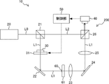
- FIG. 2 is a diagram showing an example of the configuration of the holography device 10 according to the first embodiment of the technology disclosed.
- the holography device 10 includes a laser light source 20 , an optical system 200 , an imaging section 40 and a control section 50 .
- the optical system 200 is configured to form an interference image by interference between the object light L1 and the reference light L2, and includes a demultiplexer 21, reflecting mirrors 22 and 24, an objective lens 23, an imaging lens 25, and a multiplexer. It includes an oscillator 26 , a phase shifter 30 and a rotating mechanism 31 .
- the holography device 10 according to this embodiment can be used for cell evaluation.
- a cell 60 to be evaluated is cultured on a substrate 61 and placed between the reflecting mirror 22 and the objective lens 23 while adhering to or floating from the substrate 61 .
- the type of cells 60 is not particularly limited, but may be, for example, embryonic cells that may require individual evaluation for each cell.
- a HeNe laser with a wavelength of 632.8 nm, for example, can be used for the laser light source 20 .
- a linearly polarized laser beam L0 emitted from the laser light source 20 is split into two laser beams by the demultiplexer 21 .
- One of the two laser beams is the object beam L1 and the other is the reference beam L2.
- a beam splitter can be used as the demultiplexer 21 .
- the object light L1 is incident on the reflecting mirror 22 via the phase shifter 30 held by the rotating mechanism 31 .
- the object light L1 whose traveling direction is bent by the reflecting mirror 22 is applied to the cells 60 on the substrate 61 .
- the substrate 61 may constitute containers generally used in cell culture, such as petri dishes and well plates.
- the substrate 61 is made of a material, such as polystyrene, which is transparent to the object light L1.
- Substrate 61 may be made of plastic or glass other than polystyrene.
- An image of the object light L1 that has passed through the cell 60 and the substrate 61 is magnified by the objective lens 23 .
- the object light L1 that has passed through the objective lens 23 has its traveling direction bent by the reflecting mirror 24 and enters the multiplexer 26 via the imaging lens 25 .
- the reference light L2 also enters the multiplexer 26 .
- the object light L ⁇ b>1 and the reference light L ⁇ b>2 are combined by the combiner 26 and imaged on the imaging surface of the imaging unit 40 .
- a beam splitter can be used as the multiplexer 26 .
- the imaging unit 40 includes an imaging device such as a CMOS (Complementary Metal-Oxide-Semiconductor) image sensor, and generates image data of an interference image. Image data of the interference image is supplied to the control unit 50 .
- CMOS Complementary Metal-Oxide-Semiconductor
- the phase shifter 30 is arranged between the demultiplexer 21 and the reflecting mirror 22 on the optical path of the object light L1.
- the phase shifter 30 has a function of changing the polarization direction of the object light L1. That is, the phase shifter 30 changes the polarization direction of the incident light to a direction corresponding to the rotational position of the phase shifter 30 and emits the light.
- the retarder 30 may be, for example, a half-wave plate ( ⁇ /2 plate).
- the rotation mechanism 31 rotates the phase shifter 30 around the optical axis of the object light L1 as a rotation axis based on a control signal supplied from the control unit 50 . By rotating the phase shifter 30, it is possible to set the polarization direction of the object light L1 transmitted through the phase shifter 30 to an arbitrary direction.
- An interference image of the object light L1 and the reference light L2 is formed by combining the object light L1 and the reference light L2 that have passed through the cell 60 and the substrate 61 .
- the object light L1 and the reference light L2 need to be linearly polarized and have the same polarization direction (polarization axis).
- the substrate 61 is made of a material that causes birefringence, birefringence occurs when the object light L1 passes through the substrate 61, and the object light L1 becomes elliptically polarized light.
- the polarization axis of the object light L1 is rotated, and the polarization direction of the object light L1 and the polarization direction of the reference light L2 are not aligned.
- the coherence between the object light L1 and the reference light L2 is lowered, and the contrast of the interference image is lowered.
- the control unit 50 derives an evaluation value for the interference image captured by the imaging unit 40, and controls the rotational position of the rotation mechanism 31 (and phase shifter 30) based on the evaluation value.
- the evaluation value is an index value indicating the contrast of the interference image, and may be, for example, the standard deviation or variance of pixel values in the image data of the interference image.
- a pixel value means a numerical value indicating the brightness of the pixel. The higher the coherence between the object light L1 and the reference light L2, the higher the contrast of the interference image and the larger the standard deviation or dispersion as an evaluation value.
- the evaluation value can also be said to be an index value indicating coherence between the object light L1 and the reference light L2.
- the control unit 50 controls the rotational position of the rotating mechanism 31 (and the phase shifter 30) so that the evaluation value is maximized.
- the control unit 50 includes a computer having a processor (not shown), and performs the following processes.
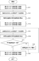
- FIG. 3 is a flowchart showing an example of the flow of processing executed by the control unit 50.
- the controller 50 sets the rotational position of the rotating mechanism 31 (and the phase shifter 30) to the initial position.
- step S ⁇ b>2 the control unit 50 acquires image data of the interference image from the imaging unit 40 .
- step S3 the control unit 50 derives an evaluation value for the image data of the interference image acquired in step S2.
- the control unit 50 derives, for example, the standard deviation of pixel values as an evaluation value and stores it in a memory (not shown).
- step S4 the control unit 50 determines whether or not the derivation of evaluation values has been completed for all predetermined rotational positions. If the control unit 50 determines that the derivation of evaluation values has not been completed for all rotational positions, the process proceeds to step S5, and if it is determined to have been completed, the process proceeds to step S6.
- step S5 the control unit 50 rotates the rotation position of the rotation mechanism 31 (and the phase shifter 30) by one step.
- the phase shifter 30 rotates by one step (for example, 5°) about the optical axis of the object light L1.
- the control unit 50 returns the process to step S2. That is, the control unit 50 acquires image data of an interference image in a state where the rotational position of the phase shifter 30 is rotated by one step, and derives an evaluation value for the image data.
- the control unit 50 repeats the processing from step S2 to step S5 until the amount of change in the polarization direction from the initial position by the phase shifter 30 reaches, for example, 180°.
- the phase shifter 30 is a half-wave plate ( ⁇ /2 plate)
- changing the phase shifter by 90° from the initial position changes the polarization direction of the object light L1 by 180°.
- step S6 the control unit 50 supplies a control signal to the rotation mechanism 31 to position the rotation mechanism 31 (and the phase shifter 30) at the rotation position where the evaluation value stored in the memory is maximized.
- the holography device 10 has the optical system 200 that forms an interference image by interference between the object light L1 and the reference light L2.
- the optical system 200 includes a phase shifter 30 arranged on the optical path of the object light L1, and a rotation mechanism 31 that rotates the phase shifter 30 around the optical axis of the object light L1 as a rotation axis.
- the holography device 10 derives an imaging unit 40 that captures an interference image, derives an evaluation value for the interference image captured by the imaging unit 40, and controls the rotational position of the rotation mechanism 31 (and phase shifter 30) based on the evaluation value.
- control unit 50 for As the evaluation value, an index value indicating the contrast state of the interference image, such as the standard deviation or dispersion of pixel values in the image data of the interference image, is used.
- the control unit 50 controls the rotational position of the rotating mechanism 31 (and the phase shifter 30) so that the evaluation value is maximized.
- the rotation mechanism 31 (and By controlling the rotational position of the phase shifter 30), the polarization direction of the object light L1 can be matched with the polarization direction of the reference light L2, thereby suppressing a decrease in the contrast of the interference image. That is, according to the holography device 10, the influence of birefringence in the substrate 61 can be suppressed.
- FIG. 4 is a graph showing an example of the relationship between the rotational position of the phase shifter 30 and the standard deviation of the pixel values of the image data of the interference image.
- FIG. 4 shows the relationship when the substrate 61 is arranged on the optical path of the object light L1 (with substrate) and when the substrate 61 is not arranged (without substrate).
- the standard deviation at the rotational position of the phase shifter 30 of 0° is descend.
- the standard deviation increased and reached its maximum value at a specific rotational position (near 35°).
- the maximum value of the standard deviation was the same between the case where the substrate 61 was arranged and the case where the substrate 61 was not arranged. This indicates that the control of the rotational position of the phase shifter 30 can improve the contrast of the interference image to the extent that the influence of the birefringence of the substrate 61 can be offset.
- the phase shifter 30 and the rotation mechanism 31 can be arranged behind the cell 60 and the substrate 61 in the traveling direction of the object light L1.
- the phase shifter 30 and the rotating mechanism 31 are arranged between the reflecting mirror 24 and the imaging lens 25 .
- the phase shifter 30 and the rotation mechanism 31 may be arranged on the optical path of the reference light L2. Also in this case, it is possible to suppress variations in the contrast of the interference image.
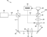
- FIG. 7 is a diagram showing an example of a configuration of a holography device 10A according to a second embodiment of technology disclosed herein.
- the holography device 10A according to the present embodiment further includes a polarizer 27, an attenuator 28, a first shutter 29A and a second shutter 29B, which is different from the holography device 10 according to the first embodiment (see FIG. 2).
- different from A polarizer 27 is arranged on the optical path of the object light L1.
- the polarizer 27 is arranged between the reflecting mirror 24 and the imaging lens 25 .
- the polarizer 27 is a polarizing filter having a function of removing a polarized component unnecessary for forming an interference image contained in the elliptically polarized light generated by the object light L1 passing through the substrate 61 .
- the attenuator 28 is arranged on the optical path of the reference light L2.
- the attenuator 28 has a function of attenuating the reference light L2 by an attenuation amount according to the control signal supplied from the control section 50 .
- the control unit 50 sets the average pixel value (average luminance value) of the image data of the image captured by the imaging unit 40 only by the object light L1 and the average pixel value (average luminance value) of the image data by only the reference light L2.
- the attenuation in the attenuator 28 is controlled so that .
- the first shutter 29A is arranged on the optical path of the object light L1.
- the first shutter 29A is arranged between the imaging lens 25 and the multiplexer 26, but it may be arranged anywhere on the optical path of the object light L1.
- the first shutter 29A switches between passage and blocking of the object light L1 according to a control signal supplied from the control section 50.
- the second shutter 29B is arranged on the optical path of the reference light L2. Although the second shutter 29B is arranged between the attenuator 28 and the multiplexer 26 in the example shown in FIG. 7, it may be arranged anywhere on the optical path of the reference light L2. The second shutter 29B switches between passing and blocking of the reference light L2 according to a control signal supplied from the control section 50. FIG.
- FIG. 8 is a flowchart showing an example of the flow of processing executed by the control unit 50 according to this embodiment. Each process shown in FIG. 8 is executed after the process shown in FIG. 3 ends.
- step S11 the control unit 50 controls the first shutter 29A to open and the second shutter 29B to close.
- the imaging unit 40 captures an image of only the object light L1.
- step S ⁇ b>12 the control unit 50 acquires image data of an image formed only by the object light L ⁇ b>1 from the imaging unit 40 .
- step S13 the control unit 50 derives the average pixel value (average luminance value) of the object light image indicated by the image data acquired in step S12, and stores it in a memory (not shown).
- step S14 the control unit 50 controls the first shutter 29A to be closed and the second shutter 29B to be opened.
- the imaging unit 40 captures an image formed only by the reference light L2.
- step S ⁇ b>15 the control unit 50 acquires image data of an image formed only by the reference light L ⁇ b>2 from the imaging unit 40 .
- step S16 the control unit 50 derives the average pixel value (average brightness value) of the reference light image indicated by the image data acquired in step S15, and stores it in a memory (not shown).
- step S17 the control unit 50 determines whether or not the average pixel value (average brightness value) of the object light image and the average pixel value (average brightness value) of the reference light image stored in the memory match. If the control unit 50 determines that the average pixel values (average luminance values) do not match, the process proceeds to step S18, and if it determines that the average pixel values (average luminance values) match, the process to step S19.
- step S18 the control unit 50 increases the attenuation amount of the attenuator 28 by one step, and returns the process to step S15. That is, the control unit 50 acquires image data, stores it in the memory, and derives the average pixel value (average luminance value) for the reference light image in which the attenuation amount in the attenuator 28 is increased by one step.
- the control unit 50 repeats the processing from step S15 to step S18 until the average pixel value (average luminance value) of the object light image and the average pixel value (average luminance value) of the reference light image stored in the memory match. Repeat.
- step S19 the control unit 50 controls the first shutter 29A to open and the second shutter 29B to open.
- the polarizer 27 removes the polarization component unnecessary for forming the interference image contained in the elliptically polarized light generated by the object light L1 passing through the substrate 61. Further, the attenuation amount of the attenuator 28 is controlled so that the light amount of the object light L1 and the light amount of the reference light L2 are the same. This promotes the effect of suppressing a decrease in the contrast of the interference image and the effect of suppressing the variation in the contrast of the interference image.
- the attenuation amount in the attenuator 28 is controlled so that the brightness of the image by the object light L1 captured by the imaging unit 40 and the brightness of the image by the reference light L2 match is illustrated.
- the attenuation amount in the attenuator 28 may be controlled so that the difference between the brightness of the image by the object light L1 and the brightness of the image by the reference light L2 is within a predetermined range.
- each holographic device The components of each holographic device are shown in Table 1 below.
- the holography device 10 according to the first embodiment does not have a polarizer and an attenuator among the components shown in Table 1.
- the holography device according to the comparative example does not include the phase shifter, rotating mechanism, polarizer, and attenuator among the components shown in Table 1. In other words, the holography device according to the comparative example has no means for correcting variations in the polarization direction of the object light caused by the birefringence of the substrate 61 .
- Embryonic cells were cultured in the 12 wells of the substrate.
- image data of interference images of embryonic cells were obtained for a total of 3 substrates at 12 locations for each substrate. That is, the number of acquisitions of interference images in each holography device is 36.
- a standard deviation of pixel values was derived for each of the acquired image data of the interference images.
- FIG. 9 is a graph showing the result of comparing the standard deviation for each well number corresponding to the imaging position of the interference image between devices.
- FIG. 10 is a graph showing the result of comparing the average value, maximum value, and minimum value of standard deviation for 36 points between devices. 9 and 10, Example 1 corresponds to the holography device 10 according to the first embodiment, Example 2 corresponds to the holography device 10A according to the second embodiment, and Comparative Example corresponds to the comparative example. Compatible with holographic devices.
- the holography device is provided with a phase shifter as a means for correcting variations in the polarization direction of the object light caused by the birefringence of the substrate 61, so that the standard deviation of the pixel values of the interference image is was confirmed to increase and the variation in standard deviation to decrease.
- a phase shifter as a means for correcting variations in the polarization direction of the object light caused by the birefringence of the substrate 61, so that the standard deviation of the pixel values of the interference image is was confirmed to increase and the variation in standard deviation to decrease.
- the cell evaluation method according to the present embodiment uses the holography device 10 according to the first embodiment or the holography device 10A according to the second embodiment.
- cells 60 cultured on a substrate 61 transparent to object light L1 are arranged on the optical path of object light L1, and the substrate 61 and cells 60 are transmitted. It includes acquiring an interference image by object light L1 and reference light L2, generating a phase image from the interference image, and evaluating cells using the phase image.
- FIGS. 11A to 11D An example of a method of acquiring a phase image from an interference image will be described below with reference to FIGS. 11A to 11D.
- Figures 11A to 11D were obtained for aggregates (spheres) of iPS cells (induced pluripotent stem cells).
- the interference image (hologram) of cells illustrated in FIG. 11A acquired by the imaging unit 40 is trimmed to a size of, for example, 2048 ⁇ 2048, and then subjected to a two-dimensional Fourier transform.
- FIG. 11B is an example of a Fourier transform image of cells obtained by this process.
- FIG. 11B shows images based on direct light, object light, and conjugate light.
- the position of the object light is specified by specifying the amount of deviation of the object light from the direct light in the Fourier transform image. Extract the amplitude component.
- the angular spectrum method is applied to reconstruct an image showing the phase of the cells at any spatial location.
- the angular spectrum U(f x , f y ; 0) of the Fourier transform image of the wavefront u(x, y; 0) captured by the imaging plane of the imaging unit 40 is obtained.
- the transfer function H (f x , f y ; z) is a frequency response function (Fourier transform of an impulse response function (Green's function)).
- the wavefront U (f x , f y ; z) at position z in the optical axis direction (z direction) is subjected to an inverse Fourier transform to obtain a solution at position z Derive u(x, y; z).
- FIG. 11C is an example of a phase image before unwrapping obtained by each of the above processes.
- phase in the phase difference image before unwrapping shown in FIG. 11C is convoluted to values between 0 and 2 ⁇ . Therefore, for example, by applying a phase unwrapping method such as Unweighted Least Squares (unweighted least squares method) or Flynn's Algorithm (Flynn's Algorithm) to join the parts of 2 ⁇ or more, as shown in FIG. 11D A final phase image can be obtained as illustrated. Many unwrapping methods have been proposed, and an appropriate method that does not cause phase mismatch may be selected as appropriate.
- phase unwrapping method such as Unweighted Least Squares (unweighted least squares method) or Flynn's Algorithm (Flynn's Algorithm)
- FIG. 12 is a diagram showing the concept of the phase image IP.
- the lower part of FIG. 12 is a three - dimensional representation of the phase amount at each pixel k of the phase image IP.
- the upper part of FIG. 12 shows the phase amount at each pixel k of the phase image IP in grayscale on a plane.
- phase image IP the phase image IP
- PS the phase image IP
- phase amount P is represented by the following equation (4).
- phase in this specification is the phase of the electric field amplitude when light is regarded as an electromagnetic wave, and is used in a more general sense.
- phase amount Pk at each pixel k of the phase image IP can be expressed by the following equation (5).
- nk is the refractive index of the cell at the site corresponding to each pixel k of the phase image IP
- dk is the thickness of the cell at the site corresponding to each pixel k of the phase image IP
- ⁇ is It is the wavelength of the object light in the hologram optical system.
- a phase image of a cell is an image that shows the optical path length distribution of the object light that has passed through the cell. Since the optical path length in the cell corresponds to the product of the refractive index of the cell and the thickness of the cell, the phase image of the cell can be obtained from the refractive index and the thickness of the cell, as shown in equation (5). (shape) information.
- An example of a cell evaluation method using a phase image is a method using the total phase amount P A derived from the phase image.
- the total phase amount P A is represented by the following equation (6).
- s is the area of each pixel k of the phase image
- vk is the volume of the cell at the site corresponding to each pixel k of the phase image.
- the total phase amount P A corresponds to the sum of the phase amounts P k for each pixel of the cell phase image for all pixels k.
- the pixel values of the phase image correspond to the phase quantity Pk .
- FIG. 13 is a graph showing the results of obtaining the correlation characteristics between the volume of iPS cell aggregates (spheres) and the total phase amount PA . As shown in FIG. 13, it was confirmed that there is a proportional relationship between the total phase amount PA and the aggregate volume.
- FIG. 13 shows a trend line L S indicating a measure of the correlation between the volume of aggregates and the total phase amount P A along with the plot.
- a regression line derived from each plot shown in FIG. 13 was applied as the trend line LS .
- FIG. 13 shows phase images of aggregates corresponding to plots a1 and a2 present on the trend line LS , and aggregates corresponding to plots a3, a4, and a5 present at positions diverging from the trend line LS .
- a phase image is shown.
- For the aggregates corresponding to plots a1 and a2 present on the trend line LS a phase image with uniform brightness throughout the aggregate was obtained. This indicates that the plurality of cells forming the aggregates is homogeneous, the density of the cells within the aggregates is uniform, and the like.
- the state of each aggregate can be determined according to the degree of divergence. Therefore, for example, for aggregates in which the negative width from the trend line LS of the total phase amount P A is equal to or greater than the threshold, the density of the plurality of cells contained in the aggregate, the homogeneity, and the outer shape of the sphere It can be determined that at least one of the is abnormal.
- phase images generated from high-contrast interference images it is preferable to use phase images generated from high-contrast interference images. That is, it is possible to use a phase image generated from an interference image captured while controlling the rotational position of the rotating mechanism 31 (and the phase shifter 30) such that the standard deviation or variance of pixel values in the interference image is maximized. preferable.
Landscapes
- Physics & Mathematics (AREA)
- General Physics & Mathematics (AREA)
- Engineering & Computer Science (AREA)
- Theoretical Computer Science (AREA)
- Computing Systems (AREA)
- Chemical & Material Sciences (AREA)
- Analytical Chemistry (AREA)
- General Health & Medical Sciences (AREA)
- Health & Medical Sciences (AREA)
- Biochemistry (AREA)
- Life Sciences & Earth Sciences (AREA)
- Optics & Photonics (AREA)
- Immunology (AREA)
- Pathology (AREA)
- Holo Graphy (AREA)
- Investigating Or Analysing Materials By Optical Means (AREA)
- Medical Informatics (AREA)
- Nuclear Medicine, Radiotherapy & Molecular Imaging (AREA)
- Radiology & Medical Imaging (AREA)
- Quality & Reliability (AREA)
- Computer Vision & Pattern Recognition (AREA)
Priority Applications (4)
| Application Number | Priority Date | Filing Date | Title |
|---|---|---|---|
| JP2023512907A JP7779905B2 (ja) | 2021-04-09 | 2022-03-18 | ホログラフィー装置及び細胞の評価方法 |
| CN202280026344.2A CN117098987A (zh) | 2021-04-09 | 2022-03-18 | 全息装置及细胞的评价方法 |
| EP22784484.2A EP4321936A4 (en) | 2021-04-09 | 2022-03-18 | HOLOGRAPHY DEVICE AND CELL ASSESSMENT METHODS |
| US18/476,317 US12591203B2 (en) | 2021-04-09 | 2023-09-28 | Holography apparatus and cell evaluation method |
Applications Claiming Priority (2)
| Application Number | Priority Date | Filing Date | Title |
|---|---|---|---|
| JP2021066769 | 2021-04-09 | ||
| JP2021-066769 | 2021-04-09 |
Related Child Applications (1)
| Application Number | Title | Priority Date | Filing Date |
|---|---|---|---|
| US18/476,317 Continuation US12591203B2 (en) | 2021-04-09 | 2023-09-28 | Holography apparatus and cell evaluation method |
Publications (1)
| Publication Number | Publication Date |
|---|---|
| WO2022215499A1 true WO2022215499A1 (ja) | 2022-10-13 |
Family
ID=83545426
Family Applications (1)
| Application Number | Title | Priority Date | Filing Date |
|---|---|---|---|
| PCT/JP2022/012806 Ceased WO2022215499A1 (ja) | 2021-04-09 | 2022-03-18 | ホログラフィー装置及び細胞の評価方法 |
Country Status (5)
| Country | Link |
|---|---|
| US (1) | US12591203B2 (https=) |
| EP (1) | EP4321936A4 (https=) |
| JP (1) | JP7779905B2 (https=) |
| CN (1) | CN117098987A (https=) |
| WO (1) | WO2022215499A1 (https=) |
Citations (9)
| Publication number | Priority date | Publication date | Assignee | Title |
|---|---|---|---|---|
| JP2003015509A (ja) | 2001-06-27 | 2003-01-17 | Sony Corp | 画像露光記録装置及び画像露光記録方法 |
| WO2008123408A1 (ja) * | 2007-04-04 | 2008-10-16 | Nikon Corporation | 3次元顕微鏡および3次元画像取得方法 |
| JP2013531787A (ja) * | 2010-05-25 | 2013-08-08 | アリックス インコーポレイテッド | 粒子の運動度および/または細胞の分散を求めるためのホログラフィック変動顕微鏡装置および方法 |
| JP2014010019A (ja) * | 2012-06-28 | 2014-01-20 | Nikon Corp | 干渉計測装置 |
| US20170356846A1 (en) * | 2014-12-17 | 2017-12-14 | Commissariat à I'énergie atomique et aux énergies alternatives | System for observing objects |
| WO2018147473A1 (ja) * | 2017-02-10 | 2018-08-16 | 国立大学法人京都工芸繊維大学 | 3次元物体情報計測装置 |
| WO2019176427A1 (ja) | 2018-03-12 | 2019-09-19 | 富士フイルム株式会社 | 判定方法 |
| WO2020261826A1 (ja) * | 2019-06-28 | 2020-12-30 | 富士フイルム株式会社 | 画像処理装置、評価システム、画像処理プログラム及び画像処理方法 |
| JP2021066769A (ja) | 2019-10-18 | 2021-04-30 | 日鉄テックスエンジ株式会社 | 窯芯検知装置 |
Family Cites Families (8)
| Publication number | Priority date | Publication date | Assignee | Title |
|---|---|---|---|---|
| JPS58176511A (ja) * | 1982-04-09 | 1983-10-17 | Hitachi Ltd | 干渉方法及びその装置 |
| JPH04269603A (ja) * | 1991-02-26 | 1992-09-25 | Olympus Optical Co Ltd | 干渉測定装置 |
| CN101509813A (zh) * | 2009-03-31 | 2009-08-19 | 昆明理工大学 | 旋转参考光偏振方向的数字全息光弹二维应力场检测方法 |
| EP2930461A4 (en) * | 2012-12-06 | 2015-12-02 | 3Dragons Llc | THREE-DIMENSIONAL FORM-MEASUREMENT DEVICE, METHOD FOR DETECTING A HOLOGRAM IMAGE, AND METHOD FOR MEASURING A THREE-DIMENSIONAL FORM |
| KR101990009B1 (ko) * | 2017-08-25 | 2019-09-30 | 주식회사 내일해 | 개선된 홀로그래픽 복원 장치 및 방법 |
| CN109946941A (zh) * | 2019-04-17 | 2019-06-28 | 上海师范大学 | 基于Sagnac效应的干涉的光学图像加密系统及方法 |
| CN110455799B (zh) * | 2019-07-23 | 2022-06-17 | 长春理工大学 | 一种用于活细胞成像的高分辨率全息显微镜及方法 |
| CN112506019B (zh) * | 2020-11-29 | 2022-05-03 | 北京工业大学 | 基于克罗内克积插值的离轴数字全息成像重建方法 |
-
2022
- 2022-03-18 EP EP22784484.2A patent/EP4321936A4/en active Pending
- 2022-03-18 JP JP2023512907A patent/JP7779905B2/ja active Active
- 2022-03-18 CN CN202280026344.2A patent/CN117098987A/zh active Pending
- 2022-03-18 WO PCT/JP2022/012806 patent/WO2022215499A1/ja not_active Ceased
-
2023
- 2023-09-28 US US18/476,317 patent/US12591203B2/en active Active
Patent Citations (9)
| Publication number | Priority date | Publication date | Assignee | Title |
|---|---|---|---|---|
| JP2003015509A (ja) | 2001-06-27 | 2003-01-17 | Sony Corp | 画像露光記録装置及び画像露光記録方法 |
| WO2008123408A1 (ja) * | 2007-04-04 | 2008-10-16 | Nikon Corporation | 3次元顕微鏡および3次元画像取得方法 |
| JP2013531787A (ja) * | 2010-05-25 | 2013-08-08 | アリックス インコーポレイテッド | 粒子の運動度および/または細胞の分散を求めるためのホログラフィック変動顕微鏡装置および方法 |
| JP2014010019A (ja) * | 2012-06-28 | 2014-01-20 | Nikon Corp | 干渉計測装置 |
| US20170356846A1 (en) * | 2014-12-17 | 2017-12-14 | Commissariat à I'énergie atomique et aux énergies alternatives | System for observing objects |
| WO2018147473A1 (ja) * | 2017-02-10 | 2018-08-16 | 国立大学法人京都工芸繊維大学 | 3次元物体情報計測装置 |
| WO2019176427A1 (ja) | 2018-03-12 | 2019-09-19 | 富士フイルム株式会社 | 判定方法 |
| WO2020261826A1 (ja) * | 2019-06-28 | 2020-12-30 | 富士フイルム株式会社 | 画像処理装置、評価システム、画像処理プログラム及び画像処理方法 |
| JP2021066769A (ja) | 2019-10-18 | 2021-04-30 | 日鉄テックスエンジ株式会社 | 窯芯検知装置 |
Non-Patent Citations (2)
| Title |
|---|
| NICOS MAGLAVERAS, IOANNA CHOUVARDA, AND PAULO DE CARVALHO: "IFMBE proceedings (International Federation for Medical and Biological Engineering)", vol. 87, 1 January 2022, SPRINGER , DE , ISSN: 1680-0737, article ACHIMOVA ELENA, ABASKIN V., CAZAC V., PRISACAR A., MASHALKIN A., LOSHMANSCHII C.: "The Anisotropy of Light Propagation in Biological Tissues", pages: 149 - 156, XP055976103, DOI: 10.1007/978-3-030-92328-0_20 * |
| See also references of EP4321936A4 |
Also Published As
| Publication number | Publication date |
|---|---|
| JPWO2022215499A1 (https=) | 2022-10-13 |
| EP4321936A4 (en) | 2024-09-18 |
| US20240027959A1 (en) | 2024-01-25 |
| EP4321936A1 (en) | 2024-02-14 |
| US12591203B2 (en) | 2026-03-31 |
| JP7779905B2 (ja) | 2025-12-03 |
| CN117098987A (zh) | 2023-11-21 |
Similar Documents
| Publication | Publication Date | Title |
|---|---|---|
| Bianco et al. | Strategies for reducing speckle noise in digital holography | |
| TWI752764B (zh) | 用於疊對測量之形貌相位控制 | |
| JP5339535B2 (ja) | デジタルホログラフィ装置及び位相板アレイ | |
| KR101159495B1 (ko) | 파면 조정 및 향상된 3?d 측정을 위한 방법 및 장치 | |
| Lai et al. | Digital wavefront reconstruction and its application to image encryption | |
| Nobukawa et al. | Bimodal incoherent digital holography for both three-dimensional imaging and quasi-infinite–depth-of-field imaging | |
| KR20100061820A (ko) | 액정 적응 광학을 사용하여 오토 포커스를 행하기 위한 방법 및 장치 | |
| JP2006023307A (ja) | 顕微鏡結像システムおよび高アパーチャ結像システムのエミュレーションのための、特にマスク検査のための方法 | |
| CN107037714B (zh) | 基于超快激光的高时间分辨全息偏振显微成像系统及方法 | |
| CN115867846A (zh) | 包括确定物体的定量色散图像的方法和数字同轴全息显微镜扫描仪 | |
| WO2018083573A1 (en) | Wavefront sensor and method of reconstructing distorted wavefronts | |
| Ibrahim | Fast phase-shifting technique for 3-D surface micro-topography measurement | |
| CN120112769A (zh) | 成像系统和方法 | |
| Das et al. | Parallel-quadrature phase-shifting digital holographic microscopy using polarization beam splitter | |
| KR101761014B1 (ko) | 마이크로 렌즈 3차원 광학 굴절률 촬영 장치 및 방법 | |
| Lin et al. | Determining the refractive index profile of micro-optical elements using transflective digital holographic microscopy | |
| WO2022215499A1 (ja) | ホログラフィー装置及び細胞の評価方法 | |
| JP2019511743A (ja) | 複屈折レンズ干渉計 | |
| JP2020190616A (ja) | ホログラム記録再生装置及び立体像再生方法 | |
| KR102897662B1 (ko) | 층밀림 간섭계를 이용한 거칠기 측정 장치 및 방법 | |
| JP7744766B2 (ja) | インコヒーレントデジタルホログラフィ撮像装置 | |
| WO2022224722A1 (ja) | 評価値の取得方法 | |
| Hsieh et al. | A simple arbitrary phase-step digital holographic reconstruction approach without blurring using two holograms | |
| Wang et al. | Dual-wavelength digital holographic phase reconstruction based on a polarization-multiplexing configuration | |
| JP6436753B2 (ja) | 位相差干渉顕微装置 |
Legal Events
| Date | Code | Title | Description |
|---|---|---|---|
| 121 | Ep: the epo has been informed by wipo that ep was designated in this application |
Ref document number: 22784484 Country of ref document: EP Kind code of ref document: A1 |
|
| WWE | Wipo information: entry into national phase |
Ref document number: 202280026344.2 Country of ref document: CN |
|
| WWE | Wipo information: entry into national phase |
Ref document number: 2023512907 Country of ref document: JP |
|
| WWE | Wipo information: entry into national phase |
Ref document number: 2022784484 Country of ref document: EP |
|
| NENP | Non-entry into the national phase |
Ref country code: DE |
|
| ENP | Entry into the national phase |
Ref document number: 2022784484 Country of ref document: EP Effective date: 20231109 |