WO2022211133A1 - レーザ溶接方法およびレーザ溶接装置 - Google Patents
レーザ溶接方法およびレーザ溶接装置 Download PDFInfo
- Publication number
- WO2022211133A1 WO2022211133A1 PCT/JP2022/017064 JP2022017064W WO2022211133A1 WO 2022211133 A1 WO2022211133 A1 WO 2022211133A1 JP 2022017064 W JP2022017064 W JP 2022017064W WO 2022211133 A1 WO2022211133 A1 WO 2022211133A1
- Authority
- WO
- WIPO (PCT)
- Prior art keywords
- section
- laser light
- laser
- scanning
- irradiation
- Prior art date
- Legal status (The legal status is an assumption and is not a legal conclusion. Google has not performed a legal analysis and makes no representation as to the accuracy of the status listed.)
- Ceased
Links
Images




Classifications
-
- B—PERFORMING OPERATIONS; TRANSPORTING
- B23—MACHINE TOOLS; METAL-WORKING NOT OTHERWISE PROVIDED FOR
- B23K—SOLDERING OR UNSOLDERING; WELDING; CLADDING OR PLATING BY SOLDERING OR WELDING; CUTTING BY APPLYING HEAT LOCALLY, e.g. FLAME CUTTING; WORKING BY LASER BEAM
- B23K26/00—Working by laser beam, e.g. welding, cutting or boring
-
- B—PERFORMING OPERATIONS; TRANSPORTING
- B23—MACHINE TOOLS; METAL-WORKING NOT OTHERWISE PROVIDED FOR
- B23K—SOLDERING OR UNSOLDERING; WELDING; CLADDING OR PLATING BY SOLDERING OR WELDING; CUTTING BY APPLYING HEAT LOCALLY, e.g. FLAME CUTTING; WORKING BY LASER BEAM
- B23K26/00—Working by laser beam, e.g. welding, cutting or boring
- B23K26/08—Devices involving relative movement between laser beam and workpiece
- B23K26/082—Scanning systems, i.e. devices involving movement of the laser beam relative to the laser head
-
- B—PERFORMING OPERATIONS; TRANSPORTING
- B23—MACHINE TOOLS; METAL-WORKING NOT OTHERWISE PROVIDED FOR
- B23K—SOLDERING OR UNSOLDERING; WELDING; CLADDING OR PLATING BY SOLDERING OR WELDING; CUTTING BY APPLYING HEAT LOCALLY, e.g. FLAME CUTTING; WORKING BY LASER BEAM
- B23K26/00—Working by laser beam, e.g. welding, cutting or boring
- B23K26/20—Bonding
- B23K26/21—Bonding by welding
Definitions
- the present invention relates to a laser welding method and a laser welding apparatus.
- Patent Document 1 A method of laser welding a plurality of metal members such as rectangular wires is known (for example, Patent Document 1).
- one of the objects of the present invention is to obtain an improved and novel laser welding method and laser welding apparatus that can, for example, suppress the generation of spatter.
- the first end of the first member made of a metal material in the first direction and the second end of the second member made of a metal material in the first direction wherein the step of arranging the first end and the second end so as to be adjacent to each other in a second direction that intersects the first direction; irradiating at least one of the second ends with a laser beam while scanning in a predetermined direction crossing the first direction; and solidifying the molten pool formed in a state of being bridged between the ends, and in the step of irradiating the laser beam, the laser beam of the first end or the second end is In the area to be irradiated, the irradiation state of the laser light is changed according to the irradiation position of the laser light.
- the power of the laser light to be irradiated may be changed according to the irradiation position of the laser light.
- the scanning path of the irradiation position of the laser beam at the first end or the second end is linearly scanned and curved. or a non-linear scanning section in which scanning is performed while bending, and in the non-linear scanning section, laser light is applied at a power lower than the power of the laser light with which at least part of the linear scanning section is irradiated. You can irradiate.
- the linear scanning section includes a first section and a second section scanned in a direction opposite to the first section, and the power of the laser beam irradiated in the first section may be the same as the maximum value of the power of the laser beam irradiated in the second section.
- the linear scanning section includes a first section and a second section scanned in a direction opposite to the first section, and the power of the laser beam irradiated in the first section may be different from the maximum value of the power of the laser beam irradiated in the second section.
- the second section is a section scanned after the first section, and the maximum power of the laser beam irradiated in the second section is irradiated in the first section. It may be larger than the maximum power of the laser light.
- the second section is a section scanned after the first section, includes the non-linear scanning section between the first section and the second section, and The one section and the second section may be separated from each other.
- the scanning path of the irradiation position of the laser light at the first end or the second end is changed according to the movement of the laser light.
- the scanning path of the irradiation position of the laser light at the first end or the second end is changed to the irradiation position while the power of the laser light to be irradiated is constant.
- the scanning path includes, as the power change section, a power increase section in which the power of the irradiated laser light is increased over time as the irradiation position of the laser light is moved immediately after the scanning of the laser light is started. may contain.
- the scanning path includes, as the power change section, a power reduction section in which the power of the irradiated laser light is reduced over time as the irradiation position of the laser light is moved immediately before the end of scanning of the laser light. may contain.
- the scanning path of the irradiation position of the laser beam at the first end or the second end is linearly scanned; a second section that is bent at a bending portion located at the end of one section and linearly scanned in a direction different from the scanning direction of the first section, and at least one of the first section and the second section
- One may include a third section in which the closer the irradiation position is to the bent portion, the lower the power of the laser beam is irradiated.
- the difference in the irradiation energy density of the laser beam depending on the location is reduced.
- the irradiation state of the laser light may be changed according to the irradiation position of the laser light.
- the laser beams include a first laser beam, a second laser beam having a wavelength higher than that of the first laser beam, and a second laser beam having a higher absorption rate with respect to the metal material of the first end portion or the second end portion; may include
- the power of the first laser beam in the step of irradiating the laser beam, the power of the first laser beam may be changed over time, and the power of the second laser beam may be kept substantially constant over time.
- the scanning path of the irradiation position of the laser beam at the first end portion or the second end portion is, before starting the irradiation with the first laser beam, A section in which scanning is performed while only the second laser light is emitted may be included.
- the laser welding method of the present invention is, for example, a laser welding method for laser welding a first member made of a metallic material and a second member made of a metallic material, wherein the first member and the second member are A step of irradiating at least one of the two members with a laser beam while scanning, and a step of solidifying a molten pool formed over the first member and the second member in the step of irradiating the laser beam. , and in the step of irradiating the laser beam, the irradiation state of the laser beam is changed according to the irradiation position of the laser beam.
- the laser welding apparatus of the present invention has a first end portion in the first direction of a first member made of a metallic material and a second end portion in the first direction of a second member made of a metallic material. , comprising a light source that outputs laser light, and an optical system that scans and irradiates at least one of the first end and the second end with the laser light from the light source and a head, and changes the irradiation state of the laser light according to the irradiation position of the laser light in the region irradiated with the laser light of the first end or the second end.
- the laser welding apparatus includes a controller that controls at least one of the output of the laser light from the light source and the scanning speed of the laser light from the optical head so as to be changeable, and a temperature sensor that detects the temperature of the molten pool.
- the controller may perform at least one of control to lower the output of the laser light from the light source and control to increase the scanning speed as the temperature detected by the temperature sensor increases.
- a controller that controls at least one of the output of the laser light from the light source and the scanning speed of the laser light from the optical head so as to be changeable; a motion sensor that detects the movement of the surface of the molten pool; wherein the control unit performs at least one of control to decrease the output of the laser light from the light source and control to increase the scanning speed as the motion of the surface detected by the motion sensor increases.
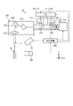
- FIG. 1 is an exemplary schematic configuration diagram of a laser welding device according to an embodiment.
- FIG. 2 is an exemplary schematic plan view showing an example of the shape of a spot of laser light irradiated onto an object from the laser welding apparatus of the embodiment.
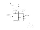
- FIG. 3 is an exemplary and schematic side view of an object before welding in the laser welding method of the embodiment.
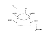
- FIG. 4 is an exemplary and schematic side view after welding of the object in the laser welding method of the embodiment.
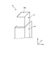
- FIG. 5 is an exemplary and schematic perspective view of a flat wire including a member as an object of the laser welding method of the embodiment.
- FIG. 6 is an exemplary and schematic plan view showing an example of a scanning path at an end portion in the laser welding method of the embodiment.
- FIG. 7 is a graph showing an example of changes in light source output according to the irradiation position in the scanning path in the laser welding method of the embodiment.
- FIG. 8 is an exemplary and schematic plan view showing an example of setting a range in which the light source output set near the edge is relatively low in the laser welding method of the embodiment.
- FIG. 9 is an exemplary schematic plan view showing an example of setting a range in which the light source output is set relatively low in the vicinity of the bent portion in the laser welding method of the embodiment.
- FIG. 10 is an exemplary and schematic plan view showing another example of the scanning path at the end in the laser welding method of the embodiment.
- FIG. 11 is an exemplary and schematic plan view showing another example of the scanning path at the end in the laser welding method of the embodiment.
- FIG. 12 is an exemplary schematic plan view showing a plurality of sections included in the scanning path of FIG. 11.
- FIG. FIG. 13 is a graph showing an example of temporal changes in light source output when scanning is performed in the scanning path of FIG. 11 and the interval of FIG. 12 .
- FIG. 14 is a graph showing another example of temporal changes in light source output when scanning is performed along the scanning path of FIG. 11 and the interval of FIG.
- FIG. 15 is an exemplary and schematic plan view showing still another example of the scanning path at the end in the laser welding method of the embodiment.
- the direction X is represented by an arrow X
- the direction Y is represented by an arrow Y
- the direction Z is represented by an arrow Z.
- Direction X, direction Y, and direction Z intersect and are orthogonal to each other.
- the Z direction is the direction in which the plurality of members that form the object W extend. Although the Z direction is substantially vertically upward, it may be tilted with respect to the vertically upward direction.
- FIG. 1 is a diagram showing a schematic configuration of a laser welding device 100 according to an embodiment.
- the laser welding device 100 includes a laser device 110 (111, 112), an optical head 120, an optical fiber 130, a driving mechanism 140, a sensor 150, and a control device 200. ing.
- the laser welding device 100 irradiates a laser beam L onto the surface of an object W to be laser-welded.
- the object W is partially melted by the energy of the laser beam L, cooled, and solidified, thereby welding the object W.
- the object W has a plurality of members, and by laser welding, a molten pool extending over the plurality of members is formed, and the plurality of members are joined by solidifying the molten pool.
- a plurality of members to be the object W can be made of, for example, a copper-based metal material such as copper or a copper alloy, an aluminum-based metal material such as aluminum or an aluminum alloy, or the like.
- a plurality of members may be made of the same metal material, or may be made of different metal materials. It should be noted that the plurality of members to be the object W may be conductors or may not be conductors.
- Each of the laser devices 111 and 112 has a laser oscillator, and is configured, for example, to output a single-mode laser beam with a power of several kW.
- the laser device 110 may include a plurality of semiconductor laser elements inside, and may be configured to output multimode laser light with a power of several kW as the total output of the plurality of semiconductor laser elements.
- the laser device 110 may also include various laser light sources such as fiber lasers, YAG lasers, disk lasers, and the like. Also, the laser device 110 outputs laser light with a wavelength of 400 [nm] or more and 1200 [nm] or less, for example.
- the laser device 111 outputs a first laser beam with a wavelength of, for example, 800 [nm] or more and 1200 [nm] or less.
- Laser device 111 may also be referred to as a first laser device.
- a laser oscillator included in the laser device 111 is a light source and can also be referred to as a first laser oscillator.
- the laser device 112 outputs a second laser beam with a wavelength of, for example, 300 [nm] or more and 600 [nm] or less.
- Laser device 112 may also be referred to as a second laser device.
- a laser oscillator included in the laser device 112 is a light source and can also be referred to as a second laser oscillator.
- the second laser light has a higher absorptance and a lower reflectance than the first laser light.
- the laser devices 111 and 112 may each output a continuous wave of laser light, or may output a pulse of laser light.
- the control device 200 can control the operation of the laser devices 111 and 112.
- the control device 200 can control the laser devices 111 and 112 to output laser light, stop outputting laser light, and change the output intensity.
- An optical fiber 130 optically connects the laser device 110 and the optical head 120 .
- the optical fiber 130 guides the laser light output from the laser device 110 to the optical head 120 .
- the laser device 110 outputs single-mode laser light
- the optical fiber 130 is configured to propagate the single-mode laser light.
- the M2 beam quality of single-mode laser light is set to 1.3 or less.
- the M2 beam quality may also be referred to as the M2 factor.
- the optical head 120 is an optical device for irradiating the object W with laser light input from the laser device 110 .
- the optical head 120 has a collimator lens 121 , a condenser lens 122 , a filter 123 , a mirror 124 , a DOE 125 and a galvanometer scanner 126 .
- Collimating lens 121, condenser lens 122, filter 123, mirror 124, DOE 125, and galvanometer scanner 126 may also be referred to as optics.
- the collimator lenses 121 collimate the laser beams input via the optical fibers 130 respectively.
- the collimated laser light becomes parallel light.
- the mirror 124 reflects the first laser beam collimated by the collimator lens 121 and directs it to the galvanometer scanner 126 .
- the filter 123 is a high-pass filter that transmits the first laser beam and reflects the second laser beam without transmitting it.
- the first laser light from mirror 124 is transmitted through filter 123 and directed to galvanometer scanner 126 .
- the second laser beam from the collimating lens 121 is reflected by the filter 123 and directed toward the galvanometer scanner 126 .
- the galvanometer scanner 126 has a plurality of mirrors 126a and 126b. By changing the angles of the plurality of mirrors 126a and 126b, it is possible to switch the emission direction of the laser light L from the optical head 120, thereby changing the irradiation position of the laser light L on the surface of the object W. .
- the angles of the mirrors 126a and 126b are respectively changed by motors (not shown) controlled by the controller 200, for example.
- the controller 200 for example.
- the condensing lens 122 condenses the laser light as parallel light coming from the galvanometer scanner 126, and irradiates the object W with the laser light L (output light).
- the DOE 125 shapes the beam of the first laser beam collimated by the collimating lens 121 .
- DOE 125 is an example of a beam shaper.
- the drive mechanism 140 changes the relative position of the optical head 120 with respect to the object W.
- the drive mechanism 140 includes, for example, a rotation mechanism such as a motor, a reduction mechanism that reduces the rotation output of the rotation mechanism, a motion conversion mechanism that converts the rotation reduced by the reduction mechanism into direct motion, and the like.
- the control device 200 can control the driving mechanism 140 so that the relative position of the optical head 120 with respect to the object W in the X, Y and Z directions is changed.
- the drive mechanism 140 can change (switch) the object W to be laser-welded among the plurality of objects W supported by the support mechanism (not shown). Further, the driving mechanism 140 can change the irradiation position of the laser beam L on the object W.
- the driving mechanism 140 can be used to change the irradiation point along with changing the irradiation direction of the laser beam with respect to the object W.
- the driving mechanism 140 can change the irradiation position while the surface of the object W is being irradiated with the laser light L.
- the driving mechanism 140 can scan the laser beam L on the surface of the object W.
- FIG. 2 is a plan view of the spot S formed on the edge 20a of the object W by irradiating the edge 20a with the laser beam L.
- the spot S includes a substantially circular irradiation area IA1 of the beam B1 of the first laser light output from the laser device 111 and a beam B2 of the second laser light output from the laser device 112. and a substantially circular irradiation area IA2 by .
- the irradiation area IA1 is positioned within the irradiation area IA2, and the center of the irradiation area IA1 substantially coincides with the center of the irradiation area IA2.
- the shape of the spot S is not limited to the example of FIG. 2, and the shapes of the irradiation areas IA1 and IA2 are not limited to circular shapes.
- the beam may be shaped by the DOE 125 so that the irradiation area IA1 includes a plurality of small areas arranged in a ring or matrix, for example. If the beam shape of the first laser beam output from the laser device 111 can be appropriately set by the DOE 125, the output of the second laser beam from the laser device 112 may be unnecessary.
- At least a part of the irradiation area IA2 should be located in front of the irradiation area IA1 in the scanning direction, and the center of the irradiation area IA1 and the center of the irradiation area IA2 are displaced from each other. good too.
- FIG. 3 is a side view showing the state of the object W before welding.
- the object W has two members 20 (21, 22). Both of the two members 20 are made of metal material. Examples of the object W shown in FIG. 3 include, for example, an example in which windings of an electromagnetic coil used in a motor of a vehicle are welded and connected to each other.
- Both of the two members 20 extend in the Z direction and have ends 20a (21a, 22a) in the Z direction.
- the end portion 20a spreads across the Z direction. That is, the end portion 20a extends in the X direction and in the Y direction.
- the Z direction is an example of a first direction.
- the end 21a is an example of a first end, and the end 22a is an example of a second end.
- the two members 20 Prior to welding, the two members 20 are arranged so as to be adjacent to each other in the X direction that intersects the Z direction and to line up in the X direction.
- a gap g is formed between the side surfaces facing each other in the X direction.
- the size of the gap g is 0 or more. That is, the two members 20 may be at least partially in contact.
- the X direction is an example of the second direction.
- the ends 21a and 22a are aligned in the X direction and are positioned at the same position in the Z direction. It may be shifted in the Z direction.
- the optical head 120 irradiates the laser beam L toward the end portion 20a.
- the irradiation direction of the laser light L is the direction opposite to the Z direction or the direction inclined with respect to the direction opposite to the Z direction.
- the laser beam L may be applied to both the end portion 21a and the end portion 22a, or may be applied to only one of the end portion 21a and the end portion 22a.
- FIG. 4 is a side view showing a state in which the welded portion 23 (molten pool) is formed on the object W.
- the two members 20 are melted at the end portion 20a, and a welded portion 23 is formed in a state in which the two end portions 20a are spanned. be.
- the welded portion 23 is formed by cooling and solidifying a molten pool formed in a state of being bridged between the two ends 20a.
- a molten pool which is a metal material having fluidity, has a shape that bulges in the Z direction due to surface tension.
- the welded portion 23 formed by solidifying the molten pool also has a bulging shape in the Z direction.
- the weld 23 mechanically connects the two members 21 and 22 .
- the welded portion 23 electrically connects the two members 21 and 22 .
- the sensor 150 (see FIG. 1) is, for example, a camera that captures the molten pool formed on the object W.
- sensor 150 is an example of a motion sensor.
- the control device 200 can acquire the movement (change over time) of the surface of the molten pool from the images acquired by the sensor 150 .
- the senor 150 may be a thermal camera capable of detecting the temperature of the molten pool.
- sensor 150 is an example of a temperature sensor.
- the control device 200 can acquire the temperature of the molten pool from the temperature image acquired by the sensor 150 .
- FIG. 5 is a perspective view of the flat wire 10 including the member 20.
- the member 20 is, for example, a core wire (inner conductor) of a rectangular wire 10 as shown in FIG.
- the rectangular wire 10 has a member 20 and a covering 30 of the member 20 .
- the member 20 is made of a conductive metal material.
- the shape of the cross section of the member 20 perpendicular to the extending direction is substantially rectangular.
- the coating 30 has insulating properties and is made of, for example, enamel or a synthetic resin material.
- the coating 30 may have an enamel layer and an extruded resin layer surrounding the enamel layer.
- the laser welding apparatus 100 is applied to welding the end portions 20a of the member 20 as the core wire of the rectangular wire 10 as described above.
- the coating 30 is removed in the vicinity of the ends of the two rectangular wires 10 in the extending direction. Then, as shown in FIG. 3 , the laser welding device 100 welds the end portions 20a of the two members 20 arranged so as to face each other in the same direction (extending direction).
- the rectangular wire 10 may constitute a segment coil provided in rotating electricity.
- the laser welding method by the laser welding apparatus 100 of this embodiment can be applied to welding the ends of adjacent segment coils set on the stator core.
- the member 20 that becomes the object W is not limited to the core wire of the rectangular wire 10, and may be members that extend in the Z direction and are adjacent to each other in the X direction, as shown in FIG. Further, the member 20 may be a plate-like member or a wire rod.
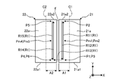
- FIG. 6 is a plan view showing an example of the scanning route R1 of the laser light L at the ends 21a and 22a. As shown in FIG. 6, in this embodiment, the laser light L is scanned along a scanning path R1 in a direction intersecting the Z direction.
- each of the end portion 21a and the end portion 22a has a rectangular shape. and has a rectangular shape that is relatively short in the X direction and relatively long in the Y direction.
- the Y direction can be referred to as the longitudinal direction and the X direction can be referred to as the lateral direction.
- the end portion 21a and the end portion 22a have the same shape, but the present invention is not limited to this.
- the laser light L is directed to an area A1 closer to the end 22a than the center C1 of the end 21a in the X direction and to the end 21a more than the center C2 of the end 22a in the X direction. are scanned in the near area A2 and .
- the scanning route R1 has sections R11, R12, R13, R14, and R15.
- the scanning route R1 is a continuous linear route connecting from the irradiation start point (irradiation position P1) to the irradiation end point (irradiation position P6).
- the end portions 21a and 22a It has been found that the temperature difference (temperature variation) depending on the location of the (molten pool) can be made smaller, and a more stable molten pool can be formed.
- the irradiation start point may also be referred to as a scan start position
- the irradiation end point may also be referred to as a scan end position.
- a section R11 is a section from the irradiation position P1 to the irradiation position P2, and a section R12 is a section from the irradiation position P2 to the irradiation position P3.
- the section R11 and the section R12 are shown shifted in the X direction for the sake of clarity. It is the same position as P3.
- the irradiation position P1 is the irradiation start point.
- the irradiation position P1 is located near the edge 21a1 opposite to the Y direction of the end 21a. Further, the irradiation position P2 is positioned near the Y-direction edge 21a2 of the end portion 21a.
- the laser beam L is scanned from the irradiation position P1 to the irradiation position P2 in a section R11 linearly extending in the Y direction, that is, in the longitudinal direction of the end portion 21a.
- the laser beam L scanned in the section R11 is bent in the opposite direction at the irradiation position P2 located at the end of the section R11, that is, folded back, and linearly extends in the opposite direction of the Y direction from the irradiation position P2 to the irradiation position P3. Scanning is performed in section R12.
- section R11 is an example of a first section
- section R12 is an example of a second section
- irradiation position P2 is an example of a bent portion.
- the section from section R11 to section R12 is an example of the bending scanning section.
- the angle change amount at the irradiation position P2 as the bending portion of the bending scanning section is 180°. In this specification, the angle change amount is set to a value of 180° or less.
- a section R13 is a section from the irradiation position P3 to the irradiation position P4.
- the irradiation position P4 is located near the edge 22a2 of the end portion 22a opposite to the Y direction.
- the laser beam L scanned in the section R12 is bent 90° at the irradiation position P3 located at the end of the section R12, and extends from the irradiation position P3 to the irradiation position P4 in the opposite direction of the X direction, i.e., the short sides of the ends 21a and 22a. Scanning is performed in a section R13 linearly extending in the direction. From section R12 to section R13, section R12 is an example of a first section, section R13 is an example of a second section, and irradiation position P3 is an example of a bending portion. Also, the section from section R12 to section R13 is an example of the bending scanning section. The angle change amount at the irradiation position P3 as the bending portion of the bending scanning section is 90°.
- a section R14 is a section from the irradiation position P4 to the irradiation position P5, and a section R15 is a section from the irradiation position P5 to the irradiation position P6.
- the section R14 and the section R15 are shown shifted in the X direction. It is the same position as P6.
- the irradiation position P5 is located near the Y-direction edge 22a2 of the end portion 22a. Further, the irradiation position P6 is the irradiation end point.
- the laser beam L scanned in the section R13 is bent 90° at the irradiation position P4 located at the end of the section R13, and extends linearly in the Y direction, that is, the longitudinal direction of the end portion 22a, from the irradiation position P4 to the irradiation position P5. Scanning is performed in the interval R14.
- section R13 is an example of a first section
- section R14 is an example of a second section
- irradiation position P4 is an example of a bent portion.
- the section from section R13 to section R14 is an example of the bending scanning section.
- the angle change amount at the irradiation position P4 as the bent portion of the bent scanning section is 90°.
- the laser beam L scanned in the section R14 is bent in the opposite direction at the irradiation position P5 located at the end of the section R14, that is, folded back, and linearly extends in the opposite direction of the Y direction from the irradiation position P5 to the irradiation position P6. Scanning is performed in section R15. From section R14 to section R15, section R14 is an example of a first section, section R15 is an example of a second section, and irradiation position P5 is an example of a bent portion. Also, the section from section R14 to section R15 is an example of the bending scanning section. The angle change amount at the irradiation position P5 as the bending portion of the bending scanning section is 180°.
- the sections R11, R12, R14, and R15 include irradiation positions farther from the edges 21a1, 21a2, 22a1, and 22a2 than the irradiation positions P1 to P6 as the ends of the sections. I'm in.
- the irradiation positions P1 to P6 are examples of irradiation ends.
- the inventors performed welding by scanning the laser beam L along the scanning path R1 in FIG.
- the first laser light having a wavelength of 1070 [nm] and , and a second laser beam having a wavelength of 450 [nm].
- a circular spot (beam) of the first laser light and a circular spot (beam) of the second laser light are concentrically arranged on a plane intersecting the Z direction of the ends 21a and 22a, and the end 21a , 22a, the diameter of the spot of the first laser beam is about 15 [ ⁇ m], and the diameter of the spot of the second laser beam is about 230 [ ⁇ m].
- the diameter of the spot can be defined as the diameter of the region including the peak of the beam and having an intensity of 1/e 2 or more of the peak intensity.
- the beam diameter can be defined as the length of the region where the intensity is 1/e2 or more of the peak intensity in the direction perpendicular to the scanning direction.
- the power distribution in the spot is not limited to a Gaussian shape.
- the scanning speed of the laser light L was kept constant at 80 [mm/s].
- the inventors conducted an experiment under the conditions described above, and found that at irradiation positions near the edges 21a1, 21a2, 22a1, 22a2 in the longitudinal direction, such as the irradiation positions P1 to P6, the edges 21a1, 21a2, 22a1, 22a1, 21a2, 22a2 It was found that the frequency of spattering is higher than that at irradiation positions farther from 22a2. This is because, in places near the edges 21a1, 21a2, 22a1, and 22a2 in the longitudinal direction, there is less metal material in the periphery than in the middle position in the longitudinal direction, so that heat tends to accumulate, and the temperature of the molten pool rises. It is presumed that the occurrence frequency of spatter is increasing.
- the inventors conducted repeated experiments and found that by appropriately changing the irradiation position of the output of the laser light, an excessive rise in the temperature of the molten pool can be suppressed. We have found that it is possible to achieve a suitable weld that is less prone to spillage.
- FIG. 7 shows the light source output (power) of the first laser light on the scanning route R1 from the irradiation position P1 to the irradiation position P6, that is, the output of the laser light from the laser device 111, depending on the irradiation position in the scanning route R1. It is a graph which shows an example of a change. Note that the output of the second laser light was constant at 150 [W].
- the light source outputs at intermediate positions Pm1, Pm2, Pm4 and Pm5 farther from the edges 21a1, 21a2, 22a1 and 22a2 , R14 and R15, and is set higher than the light source output at the irradiation positions P1, P2, P4, P5 and P6 closer to the edges 21a1, 21a2, 22a1 and 22a2.
- the scanning path R1 is bent or turned back at the irradiation positions P2 to P5.
- the time for which the spot of the laser beam stays in a relatively close range becomes longer, and regardless of the distance from the edges 21a1, 21a2, 22a1, and 22a2, It has been found that the temperature of the molten pool tends to rise more easily than in the section where the laser beam spot moves linearly without bending or folding back, which may increase the frequency of spatter generation.
- the larger the angle change amount at the bending portion of the bending scanning section described above the easier it is for the spot of the laser beam to stay at a closer position, so the temperature of the molten pool tends to rise. Therefore, the temperature rise of the molten pool can be suppressed by lowering the light source output at the bent portion as the angle change amount increases.
- the angle change amount increases.
- the temporary light source output drop amount D1 when passing through the irradiation position P2 as the bent portion in the bent scanning section where the angle change amount is 180° from the section R11 to the section R12 is It is larger than the temporary light source output decrease amount D2 when passing through the irradiation position P3 as the bent portion in the bent scanning section from the section R12 to the section R13 where the angle change amount is 90°.
- the light source output gradually and linearly changes in each of the sections R11, R12, R14, and R15.
- the setting may be such that the light source output is lowered within a range in which the light source becomes easier to light.
- FIG. 8 shows a range S3 (hatched area) in which the light source output is relatively low set near the edge 21a2 and the irradiation position P2, and a range S3 in which the light source output is relatively high outside the range S3. It is a top view which shows an example of range S4.
- Range S3 is an example of the third range and the predetermined region, and can also be referred to as an edge region.
- Range S4 is an example of the fourth range and other predetermined regions. In this way, the light source at the irradiation position included in the range (third range) within a predetermined distance from the irradiation positions P1 to P6 near the edges 21a1, 21a2, 22a1, 22a2 or the edges 21a1, 21a2, 22a1, 22a2.
- the output (power) is lower than the light source output at the irradiation position included in the range (fourth range) outside the range, or the irradiation position is the center of the members 21 and 22 in the Y direction, for example, 80 [ %], for example, it is possible to suppress the occurrence of spatter in the range S3, and to suppress the spillage of the molten pool.
- the width of the range S3 in the Y direction is preferably 2.4 [mm] or less, more preferably 1.8 [mm] or less.
- the ratio of the Y-direction width of the range S3 to the Y-direction dimension of the member 21 is 0. It is preferably 8 or less, more preferably 0.6 or less.
- FIG. 9 shows a range S1 (hatched area) in which the light source output is relatively low within a predetermined distance centering on the irradiation position P3 as the bent portion, and the light source output outside the range S1. It is a top view which shows an example of range S2 made relatively high. Range S1 is an example of the first range and the predetermined area, and range S2 is an example of the second range and another predetermined area.
- the light source output (power) at the irradiation position included in the range (first range) within a predetermined distance from the irradiation positions P2 to P5 as the bending portion is changed to the range outside the range (second range)
- the light source output lower than that at the irradiation positions included in , there is an advantage that the generation of spatter in the range S1 can be suppressed, for example.
- the bent portion is formed when the scanning direction of the laser beam changes by a predetermined angle (eg, 45 degrees) or more, and the radius of curvature of the scanning trajectory of the laser beam is a predetermined value (eg, 1.0 mm) or less. can be defined as the region where
- the lower the scanning speed the lower the light source output.
- the higher the light source output the higher the scanning speed.
- the light source output may be lowered, more preferably by 50% or more.
- the predetermined value is half the original scanning speed and can also be referred to as the threshold speed. According to such a setting, it is possible to suppress an increase in irradiation energy density due to an increase in light source output by increasing the scanning speed.
- the scanning speed is an example of the irradiation state of the laser light.
- the area of the cross section of the object W perpendicular to the irradiation direction of the laser beam is 30 [mm 2 ] or less, more preferably 20 [mm 2 ] or less, and still more preferably 10 [mm 2 ] or less, This is preferable because the frequency of spatter generation can be increased and the molten pool can be prevented from falling off the ends 21a and 22a.
- the rate of increase in temperature of the end portions 21a and 22a is slower than after the start of scanning.
- the light source output of the first laser beam is increased, a keyhole is generated and the temperature rises locally, making the molten pool unstable and possibly generating spatter. Therefore, the light source output of the second laser beam at the irradiation position P1 may be set higher than the light source output of the second laser beam after the start of scanning.
- the temperature of the end portions 21a and 22a can be raised more gently by the irradiation of the second laser beam having a higher absorptivity, and the molten pool can be formed more stably, which in turn reduces the sputtering. The occurrence can be suppressed.
- control device 200 acquires the movement amount (amplitude) of the surface of the molten pool from the image acquired by the sensor 150, and when the movement amount becomes large, the laser beam L is adjusted so that the irradiation energy density becomes low. , or the scanning speed of the laser beam L may be increased.
- the control device 200 controls the laser device 110 to lower the light source output when the movement amount exceeds a threshold value, or to lower the light source output as the movement amount increases. be able to.
- the control device can increase the scanning speed when the amount of movement exceeds a threshold value, or increase the scanning speed as the amount of movement increases. . According to such control, the molten pool can be more stabilized, and the occurrence of spatter can be suppressed.
- the control device 200 acquires the temperature of the molten pool from the image acquired by the sensor 150, and based on the temperature of the molten pool, for example, according to the irradiation position, the temperature of the molten pool is within a predetermined range. It is possible to control the irradiation state of the laser light, that is, the light source output and the scanning speed. Specifically, for example, by controlling the laser device 110, the control device 200 can lower the light source output when the temperature exceeds a threshold value, or lower the light source output as the temperature rises. can. Further, by controlling the galvanometer scanner 126 and the driving mechanism 140, the control device can increase the scanning speed when the temperature exceeds the threshold value, or increase the scanning speed as the temperature increases.
- the molten pool can be more stabilized, and the occurrence of spatter can be suppressed.
- the sensor 150 may detect the state of radiation emitted from the molten pool.
- the state of the emitted light that can be detected by the sensor 150 and that changes according to the temperature of the molten pool includes, for example, the intensity and wavelength.
- the control device 200 acquires the temperature of the molten pool from the detected value of the sensor 150 based on the correlation between the detected value and the temperature, and adjusts the temperature of the molten pool to the irradiation position, for example, so that the temperature of the molten pool falls within a predetermined range.
- the irradiation state of the laser light that is, the light source output and the scanning speed can be controlled accordingly.
- FIG. 10 is a plan view showing an example of the scanning route R2 of the laser light L at the ends 21a and 22a.
- the laser beam L is scanned along the scanning path R2 in the direction crossing the Z direction.
- the scanning route R2 includes a section R21 extending in the Y direction from an irradiation position P1 near the edge 21a1 on the end portion 21a to an irradiation position P2 near the edge 21a2, and an irradiation position from the irradiation position P2 to an irradiation position near the edge 22a2 on the end portion 22a.
- a section R24 extending in the X direction up to the position P4 is included.
- irradiation positions P2, P3, and P4 are bending portions with an angle change amount of 90°.
- FIG. 11 is a plan view showing an example of the scanning route R100 of the laser light L at the ends 21a and 22a.
- the spot S (see FIG. 2) of the laser beam L moves (is scanned) along the scanning route R100 in the direction intersecting the Z direction.
- a scanning route R100 indicates the locus of movement of the center of the spot S.
- the laser light L is scanned in a substantially U shape on the end portion 21a, and then scanned in a substantially U shape on the end portion 22a.
- scanning path R100 is set within areas A1 and A2.
- the shape of the scanning route R100 on the end portion 21a and the shape of the scanning route R100 on the end portion 22a are substantially the same. Further, the laser light L is not emitted from the optical head 120 on the movement path T between the end portions 21a and 22a.
- FIG. 12 is a plan view of the scanning route R100 of the laser light L at each end 21a, 22a. 12, the scanning path R100 is drawn with a width for the sake of clarity, but the width of the scanning path R100 in FIG. 12 is irrelevant to the size of the spot S.
- the scanning route R100 includes sections R101 to R109 in this order.
- the spot S moves linearly in the Y direction in the sections R101 to R105.
- section R106 the spot S moves while curving in a substantially U-shape that opens in the opposite direction of the Y direction.
- the spot S moves linearly in the direction opposite to the Y direction in the sections R107 to R109.
- sections R101 to R105 and sections R107 to R109 are examples of linear scanning sections
- section R106 is an example of non-linear scanning sections.
- Sections R101 to R105 are an example of a first section
- sections R107 to R109 are an example of a second section.
- sections R101 to R105 and sections R107 to R109 are separated from each other in the X direction, section R106 is smoothly connected to these sections R101 to R105 and sections R107 to R109, and has a predetermined radius.
- curved at The radius of curvature of section R106 is half the distance in the X direction of sections R101-R105 and sections R107-R109.
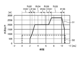
- FIG. 13 is a graph showing an example of temporal changes in the light source output (power) in the scanning path R100 shown in FIG. 12 at each end 21a, 22a.
- the solid line indicates the total output value of the laser device 111 that outputs the first laser light forming the beam B1, and the total output value of the laser device 112 that outputs the second laser light forming the beam B2. is indicated by a solid line.
- the light source output corresponding to beam B2 is constant between sections R101 to R109.
- the light source output corresponding to beam B1 is 0 in section R101, is constant in sections R104 and R108, and changes with time in sections R102, R103, R105, R107 and R109.
- sections R101, R104, and R108 are examples of constant power sections in which the irradiation position (spot S) moves while the power of the laser light L emitted from the optical head 120 is constant.
- Sections R102, R103, and R107 are examples of power increase sections in which the irradiation position (spot S) moves while the power of the laser light L emitted from the optical head 120 increases over time. is an example.
- Sections R105 and R109 are examples of power reduction sections in which the irradiation position (spot S) moves while the power of the laser light L emitted from the optical head 120 decreases over time.
- the light source output in the section R106 is set to be lower than the light source output in the sections R104 and R108 before and after it, for example, 80% or less. This is because the spot S of the laser beam L stays relatively close during movement in a non-linear scanning section such as a curved section like section R106 or a crooked (bent) section (not shown). , the irradiation energy density tends to be high. Therefore, as in the example of FIG.
- the other sections R101 to It suppresses the irradiation energy density from becoming higher than R105, R107 to R109, reduces the difference (variation) in the irradiation energy density depending on the location of the end portions 21a and 22a, and eventually spatters due to excessive temperature rise of the molten pool. , it is possible to suppress the spillage of the molten pool.
- sections R102, R103, and R107 in which the light source output increases with time, it is possible to suppress the occurrence of spatter due to an excessive temperature rise of the molten pool and the spillage of the molten pool.
- the increase over time may be a gradual increase or a stepwise increase.
- the sections where the light source output decreases with time such as sections R105 and R109, the formation of voids due to an increase in movement of the molten pool, such as disappearance of keyholes due to a rapid temperature drop of the molten pool. It is possible to suppress the occurrence of contamination and the occurrence of spatter.
- the decrease over time may be a gradual decrease or a stepwise decrease.
- the power increase rate or decrease rate (change rate) in sections R102, R103, R105, R107, and R109 can be appropriately set so that the state of the molten pool becomes moderate.
- the rate of decrease (rate of change) may be changed over time.
- the light source output in section R104 that is, the maximum value of the light source output in sections R101 to R105 in which the spot S moves in the Y direction
- the light source output in section R108 that is, the spot S moves in the Y direction.
- the maximum value of the light source output in the section R107 to R109 moving in the opposite direction is the same. In this case, for example, more energy can be supplied in a shorter time, so the processing time can be shortened, or the operation of the laser devices 111 and 112 can be managed more easily. You get the advantage.
- the second laser light has a relatively high absorption rate in the material, it has a short wavelength and relatively low convergence, so it is difficult to efficiently apply energy.
- the first laser light has a relatively low absorptivity in the material, but has a long wavelength and relatively high convergence, so it is easy to apply energy to the object W more efficiently. Therefore, by irradiating the second laser beam, the object W is preliminarily heated in a stage before the irradiation of the first laser beam, and by irradiating the first laser beam, the energy for melting the object W is input. Therefore, the object W can be melted more efficiently while suppressing rapid temperature changes of the object W.
- the beam B1 of the first laser light is irradiated from a stage before the irradiation. It is preferable to irradiate only the beam B2 of two laser beams.
- the irradiation start position Ps0 of the second laser light and the irradiation start position Ps1 of the first laser light are different from each other.
- the irradiation end position Pe of the first laser beam and the second laser beam in the Y direction corresponds to the irradiation start position Ps0 of the second laser beam in the Y direction and the irradiation start position Ps0 of the first laser beam in the Y direction.
- it is different from both of the start positions Ps1 it is not limited to this, and their relative positional relationship can be appropriately set so that the state of the molten pool becomes moderate.
- the second laser light may be irradiated at a fixed point without scanning for a certain period of time at the start of irradiation.
- the temperature of the object W can be raised to an appropriate temperature more quickly, and the object W can be processed more efficiently.
- the light source output of the second laser beam is set substantially constant over time as in the example of FIG. It is preferable to change the light source output of the first laser light over time.
- FIG. 14 is a graph showing another example of temporal changes in the light source output (power) in the scanning path R100 shown in FIG. 12 at each end 21a, 22a.
- the solid line indicates the total output value of the laser device 111 that outputs the first laser light forming the beam B1, and the total output value of the laser device 112 that outputs the second laser light forming the beam B2. is indicated by a solid line.
- the light source output in section R104 is set lower than the light source output in section R108.
- Experimental research by the inventors has revealed that, in sections R102 and R103, when the light source output of the laser device 111 suddenly rises from a low state, the molten pool moves violently and spatters are likely to occur in some cases. Therefore, in the example of FIG. 14, the light source output in section R104 is set lower than the light source output in section R108.
- the maximum value of the light source output in the section R101 to R105 is set lower than the maximum value of the light source output in the section R107 to R109.
- the value of the light source output in section R104 is set to the same value as the light source output in section R106 in the example of FIG. 14, but is not limited to this.
- the setting can be appropriately changed, such as setting the light source output to be lower than that of the section R108.
- an increase in light source output may be appropriately replaced with a decrease in scanning speed, and a decrease in light source output may be appropriately replaced with an increase in scanning speed.
- FIG. 15 is a plan view showing an example of the scanning route R100 of the laser light L at the ends 21a and 22a.
- the laser light L scans the ends 21a and 22a in a substantially U shape.
- the laser light L is at least partially distributed from regions outside the regions A1 and A2, that is, from the X-direction centers C1 and C2 of one of the ends 21a and 22a. are also scanned in regions far from the other end. Even when the laser beam L is scanned along the scanning path R100, the required welded portion 23 can be formed, and the generation of spatter due to an excessive temperature rise of the molten pool and the spillage of the molten pool can be suppressed.
- the required welded portion 23 can be formed, and the generation of spatter due to an excessive temperature rise of the molten pool and the spillage of the molten pool can be suppressed.
- the present embodiment in order to reduce the difference in the irradiation energy density of the laser light depending on the location in the regions irradiated with the laser light at the end portions 21a and 22a, The irradiation state of laser light can be changed. As a result, it is possible to suppress an excessive rise in the temperature of the molten pool, which leads to various effects such as suppressing the occurrence of spatter and suppressing spillage due to excessive growth of the molten pool.
- the object was a rectangular wire, but the object is not limited to this, and may be other conducting wires or other metal members. Also, the object may include three or more members. Also, the plurality of members included in the target object may not be the same member. Moreover, the target object is not limited to a plurality of members arranged side by side or butted against each other, and may be a plurality of superimposed members.
- known wobbling, weaving, output modulation, etc. may be performed to adjust the surface area of the molten pool.
- the position to be scanned that is, the irradiation area and the scanning path are not limited to the above examples, and can be set in various ways.
- the present invention can be implemented in the following modes.
- (21) In the laser welding method of the present invention, in at least a part of the power change section, even if the power increase rate or power decrease rate of the irradiated laser light changes over time according to the movement of the irradiation position of the laser light. good.
- (22) In the laser welding method, in the step of irradiating the laser beam, when a predetermined region of the first end portion or the second end portion is irradiated with the laser beam, another predetermined region is irradiated with the laser beam.
- the laser light may be applied at a lower output than in the case.
- the predetermined area may include a bent portion in the scanning path of the laser beam, and the other predetermined area may be an area other than the predetermined area.
- the predetermined region may be an edge region of the first end, and the other predetermined region may be a region other than the edge region of the first end.
- the predetermined region may be an edge region of the first end, and the other predetermined region may include a center of the first end in the predetermined direction.
- the scanning speed of the laser beam at the first end portion or the second end portion may be changed according to the irradiation position of the laser beam.
- the lower the scanning speed of the laser light at the first end portion or the second end portion the lower the power of the laser light to be irradiated.
- the power of the laser light to be irradiated is increased as the radius of curvature of the scanning path of the laser light at the first end or the second end is increased, or A lower scanning speed may be used.
- the scanning path of the irradiation position of the laser beam at the first end or the second end is linearly scanned; a second section which is bent at a bending portion located at the end of one section and linearly scanned in a direction different from the scanning direction of the first section; and the first section, the second section, or the bending section.
- laser light that is outside the first range and emits laser light with a power higher than that of the first range.
- the scanning path of the irradiation position of the laser beam at the first end or the second end is linearly scanned; a second section that is bent at a bending portion positioned at the end of one section and linearly scanned in a direction different from the scanning direction of the first section, from the first section toward the second section;
- a plurality of different bending scanning sections may be provided, and in the plurality of bending scanning sections, the larger the angular change amount, the larger the temporary power reduction amount.
- the scanning path of the irradiation position of the laser beam at the first end portion or the second end portion is the edge of the first end portion or the second end portion.
- a fourth section including an irradiation end close to an edge and an irradiation position farther from the edge than the irradiation end, and in the fourth section, the closer the irradiation position is to the irradiation end, the lower the Laser light may be applied with high power.
- the scanning path of the irradiation position of the laser beam at the first end portion or the second end portion is the edge of the first end portion or the second end portion.
- a fourth section including an irradiation end close to an edge and an irradiation position farther from the edge than the irradiation end, and from the edge or the irradiation end in the fourth section or the irradiation end It may include a third range within a predetermined distance, and a fourth range outside the third range in the fourth section, in which laser light is irradiated with a power higher than that of the third range.
- the second laser beam in the step of irradiating the laser beam, may be irradiated at the scanning start position with a power higher than that at the irradiation position after the scanning is started.
- the temperature of the molten pool is detected in the step of irradiating the laser beam, and the laser beam is emitted according to the irradiation position of the laser beam so that the higher the temperature of the molten pool, the lower the irradiation energy density. You may change the irradiation state.
- the laser welding method in the step of irradiating the laser beam, the movement of the molten pool is detected, and the laser beam is emitted according to the irradiation position of the laser beam so that the larger the movement of the molten pool, the lower the irradiation energy density. You may change the irradiation state.
- metal materials of the first member and the second member may be either copper-based metal or aluminum-based metal, respectively.
- the metallic material of the first member and the second member may be a conductive material.
- a laser welding method of the present invention is a laser welding method for laser welding a first member made of a metallic material and a second member made of a metallic material, wherein the first member and the second member are A step of irradiating at least one with a laser beam while scanning, and a step of solidifying a molten pool formed over the first member and the second member in the step of irradiating the laser beam,
- the irradiation state of the laser light may be changed according to the irradiation position of the laser light based on the temperature of the molten pool or the state of the radiant light output from the molten pool.
- the present invention can be used for laser welding methods and laser welding devices.
- Section (first section, linear scanning section, constant power section) R102... section (first section, linear scanning section, power change section, power increase section) R103 ... section (first section, linear scanning section, power change section, power increase section) R104 ... section (first section, linear scanning section, constant power section) R105... Sections (first section, linear scanning section, power change section, power decrease section, power constant section) R106... section (non-linear scanning section, constant power section) R107 ... section (second section, linear scanning section, power change section, power increase section) R108 ... section (second section, linear scanning section, constant power section) R109 ... section (second section, linear scanning section, power change section, power increase section) S... Spot S1... Range (first range) S2... range (second range) S3 ... range (third range) S4 ... range (fourth range) T... movement path W... object X... direction (second direction) Y... direction (third direction) Z direction (first direction)
Landscapes
- Physics & Mathematics (AREA)
- Optics & Photonics (AREA)
- Engineering & Computer Science (AREA)
- Plasma & Fusion (AREA)
- Mechanical Engineering (AREA)
- Laser Beam Processing (AREA)
Priority Applications (2)
| Application Number | Priority Date | Filing Date | Title |
|---|---|---|---|
| JP2023511766A JP7585464B2 (ja) | 2021-04-02 | 2022-04-04 | レーザ溶接方法およびレーザ溶接装置 |
| JP2024166716A JP2024169684A (ja) | 2021-04-02 | 2024-09-25 | レーザ溶接方法およびレーザ溶接装置 |
Applications Claiming Priority (2)
| Application Number | Priority Date | Filing Date | Title |
|---|---|---|---|
| JP2021063779 | 2021-04-02 | ||
| JP2021-063779 | 2021-04-02 |
Publications (1)
| Publication Number | Publication Date |
|---|---|
| WO2022211133A1 true WO2022211133A1 (ja) | 2022-10-06 |
Family
ID=83459654
Family Applications (1)
| Application Number | Title | Priority Date | Filing Date |
|---|---|---|---|
| PCT/JP2022/017064 Ceased WO2022211133A1 (ja) | 2021-04-02 | 2022-04-04 | レーザ溶接方法およびレーザ溶接装置 |
Country Status (2)
| Country | Link |
|---|---|
| JP (2) | JP7585464B2 (https=) |
| WO (1) | WO2022211133A1 (https=) |
Cited By (3)
| Publication number | Priority date | Publication date | Assignee | Title |
|---|---|---|---|---|
| CN116833563A (zh) * | 2023-07-21 | 2023-10-03 | 联合汽车电子有限公司 | 一种扁线电机定子焊接工艺 |
| KR20240053919A (ko) * | 2022-10-18 | 2024-04-25 | 주식회사휴비스 | 레이저 용접 광학장치 |
| CN119839406A (zh) * | 2025-03-19 | 2025-04-18 | 佛山市宝燊装备制造有限公司 | 一种不规则焊缝的追踪焊接控制方法、系统及设备 |
Citations (5)
| Publication number | Priority date | Publication date | Assignee | Title |
|---|---|---|---|---|
| JP2006297464A (ja) * | 2005-04-22 | 2006-11-02 | Miyachi Technos Corp | レーザ溶接方法及びレーザ溶接装置 |
| JP2011224655A (ja) * | 2010-03-30 | 2011-11-10 | Jfe Steel Corp | レーザ溶接鋼管の製造方法 |
| JP2016046132A (ja) * | 2014-08-25 | 2016-04-04 | 古河電気工業株式会社 | 黄銅圧着端子、ワイヤーハーネス及び黄銅圧着端子の製造方法 |
| WO2019159737A1 (ja) * | 2018-02-19 | 2019-08-22 | 株式会社小田原エンジニアリング | レーザ溶接方法及びレーザ溶接システム |
| JP2019181506A (ja) * | 2018-04-09 | 2019-10-24 | トヨタ自動車株式会社 | 平角線のレーザ溶接方法 |
Family Cites Families (3)
| Publication number | Priority date | Publication date | Assignee | Title |
|---|---|---|---|---|
| JP2007203346A (ja) * | 2006-02-02 | 2007-08-16 | Fanuc Ltd | レーザ制御方法及びレーザ制御装置 |
| JP6390672B2 (ja) * | 2016-08-02 | 2018-09-19 | トヨタ自動車株式会社 | 平角線のレーザ溶接方法 |
| JP2018030162A (ja) * | 2016-08-26 | 2018-03-01 | ファナック株式会社 | レーザ制御装置 |
-
2022
- 2022-04-04 JP JP2023511766A patent/JP7585464B2/ja active Active
- 2022-04-04 WO PCT/JP2022/017064 patent/WO2022211133A1/ja not_active Ceased
-
2024
- 2024-09-25 JP JP2024166716A patent/JP2024169684A/ja active Pending
Patent Citations (5)
| Publication number | Priority date | Publication date | Assignee | Title |
|---|---|---|---|---|
| JP2006297464A (ja) * | 2005-04-22 | 2006-11-02 | Miyachi Technos Corp | レーザ溶接方法及びレーザ溶接装置 |
| JP2011224655A (ja) * | 2010-03-30 | 2011-11-10 | Jfe Steel Corp | レーザ溶接鋼管の製造方法 |
| JP2016046132A (ja) * | 2014-08-25 | 2016-04-04 | 古河電気工業株式会社 | 黄銅圧着端子、ワイヤーハーネス及び黄銅圧着端子の製造方法 |
| WO2019159737A1 (ja) * | 2018-02-19 | 2019-08-22 | 株式会社小田原エンジニアリング | レーザ溶接方法及びレーザ溶接システム |
| JP2019181506A (ja) * | 2018-04-09 | 2019-10-24 | トヨタ自動車株式会社 | 平角線のレーザ溶接方法 |
Cited By (4)
| Publication number | Priority date | Publication date | Assignee | Title |
|---|---|---|---|---|
| KR20240053919A (ko) * | 2022-10-18 | 2024-04-25 | 주식회사휴비스 | 레이저 용접 광학장치 |
| KR102728091B1 (ko) * | 2022-10-18 | 2024-11-08 | 주식회사휴비스 | 레이저 용접 광학장치 |
| CN116833563A (zh) * | 2023-07-21 | 2023-10-03 | 联合汽车电子有限公司 | 一种扁线电机定子焊接工艺 |
| CN119839406A (zh) * | 2025-03-19 | 2025-04-18 | 佛山市宝燊装备制造有限公司 | 一种不规则焊缝的追踪焊接控制方法、系统及设备 |
Also Published As
| Publication number | Publication date |
|---|---|
| JP2024169684A (ja) | 2024-12-05 |
| JPWO2022211133A1 (https=) | 2022-10-06 |
| JP7585464B2 (ja) | 2024-11-18 |
Similar Documents
| Publication | Publication Date | Title |
|---|---|---|
| WO2022211133A1 (ja) | レーザ溶接方法およびレーザ溶接装置 | |
| US12397369B2 (en) | Welding method and welding apparatus | |
| KR102870602B1 (ko) | 레이저 용접 방법 및 레이저 용접 장치 | |
| CN116323069A (zh) | 激光焊接方法以及激光焊接装置 | |
| CN115697623B (zh) | 汇流条以及汇流条的制造方法 | |
| JP2025100655A (ja) | レーザ溶接方法およびレーザ溶接装置 | |
| EP4238684B1 (en) | Welding method and laser device | |
| JP2023059864A (ja) | レーザ溶接方法およびレーザ溶接装置 | |
| JP2025082124A (ja) | 金属接合体、レーザ溶接方法、およびレーザ溶接装置 | |
| JP2024052264A (ja) | レーザ溶接方法およびレーザ溶接装置 | |
| JP2024052263A (ja) | レーザ溶接方法およびレーザ溶接装置 | |
| JP6902378B2 (ja) | 溶接装置および溶接方法 | |
| JP7570044B2 (ja) | 積層金属箔のレーザー溶接方法 | |
| TWI869688B (zh) | 雷射銲接方法 | |
| JP2024076250A (ja) | レーザ溶接方法およびレーザ溶接装置 | |
| JPS6253566B2 (https=) | ||
| JP7570051B1 (ja) | 積層金属箔のレーザー溶接方法 | |
| JP7847190B1 (ja) | レーザ溶接機及びレーザ溶接方法 | |
| JP2023110638A (ja) | 溶接方法およびレーザ装置 | |
| WO2024135538A1 (ja) | レーザ溶接方法 | |
| JP5013720B2 (ja) | レーザ加工法 | |
| JP2024139513A (ja) | レーザ溶接方法およびレーザ溶接装置 | |
| JP2024072000A (ja) | レーザ加工装置及びレーザ加工方法 | |
| JP2024175078A (ja) | 積層金属箔のレーザー溶接方法 | |
| JP2023112742A (ja) | レーザ溶接装置及びこれを用いたレーザ溶接方法 |
Legal Events
| Date | Code | Title | Description |
|---|---|---|---|
| 121 | Ep: the epo has been informed by wipo that ep was designated in this application |
Ref document number: 22781340 Country of ref document: EP Kind code of ref document: A1 |
|
| WWE | Wipo information: entry into national phase |
Ref document number: 2023511766 Country of ref document: JP |
|
| NENP | Non-entry into the national phase |
Ref country code: DE |
|
| 122 | Ep: pct application non-entry in european phase |
Ref document number: 22781340 Country of ref document: EP Kind code of ref document: A1 |