WO2022211133A1 - レーザ溶接方法およびレーザ溶接装置 - Google Patents
レーザ溶接方法およびレーザ溶接装置 Download PDFInfo
- Publication number
- WO2022211133A1 WO2022211133A1 PCT/JP2022/017064 JP2022017064W WO2022211133A1 WO 2022211133 A1 WO2022211133 A1 WO 2022211133A1 JP 2022017064 W JP2022017064 W JP 2022017064W WO 2022211133 A1 WO2022211133 A1 WO 2022211133A1
- Authority
- WO
- WIPO (PCT)
- Prior art keywords
- section
- laser light
- laser
- scanning
- irradiation
- Prior art date
- Legal status (The legal status is an assumption and is not a legal conclusion. Google has not performed a legal analysis and makes no representation as to the accuracy of the status listed.)
- Ceased
Links
Images







Classifications
-
- B—PERFORMING OPERATIONS; TRANSPORTING
- B23—MACHINE TOOLS; METAL-WORKING NOT OTHERWISE PROVIDED FOR
- B23K—SOLDERING OR UNSOLDERING; WELDING; CLADDING OR PLATING BY SOLDERING OR WELDING; CUTTING BY APPLYING HEAT LOCALLY, e.g. FLAME CUTTING; WORKING BY LASER BEAM
- B23K26/00—Working by laser beam, e.g. welding, cutting or boring
- B23K26/08—Devices involving relative movement between laser beam and workpiece
- B23K26/082—Scanning systems, i.e. devices involving movement of the laser beam relative to the laser head
-
- B—PERFORMING OPERATIONS; TRANSPORTING
- B23—MACHINE TOOLS; METAL-WORKING NOT OTHERWISE PROVIDED FOR
- B23K—SOLDERING OR UNSOLDERING; WELDING; CLADDING OR PLATING BY SOLDERING OR WELDING; CUTTING BY APPLYING HEAT LOCALLY, e.g. FLAME CUTTING; WORKING BY LASER BEAM
- B23K26/00—Working by laser beam, e.g. welding, cutting or boring
- B23K26/20—Bonding
- B23K26/21—Bonding by welding
Definitions
- the present invention relates to a laser welding method and a laser welding apparatus.
- Patent Document 1 A method of laser welding a plurality of metal members such as rectangular wires is known (for example, Patent Document 1).
- one of the objects of the present invention is to obtain an improved and novel laser welding method and laser welding apparatus that can, for example, suppress the generation of spatter.
- the first end of the first member made of a metal material in the first direction and the second end of the second member made of a metal material in the first direction wherein the step of arranging the first end and the second end so as to be adjacent to each other in a second direction that intersects the first direction; irradiating at least one of the second ends with a laser beam while scanning in a predetermined direction crossing the first direction; and solidifying the molten pool formed in a state of being bridged between the ends, and in the step of irradiating the laser beam, the laser beam of the first end or the second end is In the area to be irradiated, the irradiation state of the laser light is changed according to the irradiation position of the laser light.
- the power of the laser light to be irradiated may be changed according to the irradiation position of the laser light.
- the scanning path of the irradiation position of the laser beam at the first end or the second end is linearly scanned and curved. or a non-linear scanning section in which scanning is performed while bending, and in the non-linear scanning section, laser light is applied at a power lower than the power of the laser light with which at least part of the linear scanning section is irradiated. You can irradiate.
- the linear scanning section includes a first section and a second section scanned in a direction opposite to the first section, and the power of the laser beam irradiated in the first section may be the same as the maximum value of the power of the laser beam irradiated in the second section.
- the linear scanning section includes a first section and a second section scanned in a direction opposite to the first section, and the power of the laser beam irradiated in the first section may be different from the maximum value of the power of the laser beam irradiated in the second section.
- the second section is a section scanned after the first section, and the maximum power of the laser beam irradiated in the second section is irradiated in the first section. It may be larger than the maximum power of the laser light.
- the second section is a section scanned after the first section, includes the non-linear scanning section between the first section and the second section, and The one section and the second section may be separated from each other.
- the scanning path of the irradiation position of the laser light at the first end or the second end is changed according to the movement of the laser light.
- the scanning path of the irradiation position of the laser light at the first end or the second end is changed to the irradiation position while the power of the laser light to be irradiated is constant.
- the scanning path includes, as the power change section, a power increase section in which the power of the irradiated laser light is increased over time as the irradiation position of the laser light is moved immediately after the scanning of the laser light is started. may contain.
- the scanning path includes, as the power change section, a power reduction section in which the power of the irradiated laser light is reduced over time as the irradiation position of the laser light is moved immediately before the end of scanning of the laser light. may contain.
- the scanning path of the irradiation position of the laser beam at the first end or the second end is linearly scanned; a second section that is bent at a bending portion located at the end of one section and linearly scanned in a direction different from the scanning direction of the first section, and at least one of the first section and the second section
- One may include a third section in which the closer the irradiation position is to the bent portion, the lower the power of the laser beam is irradiated.
- the difference in the irradiation energy density of the laser beam depending on the location is reduced.
- the irradiation state of the laser light may be changed according to the irradiation position of the laser light.
- the laser beams include a first laser beam, a second laser beam having a wavelength higher than that of the first laser beam, and a second laser beam having a higher absorption rate with respect to the metal material of the first end portion or the second end portion; may include
- the power of the first laser beam in the step of irradiating the laser beam, the power of the first laser beam may be changed over time, and the power of the second laser beam may be kept substantially constant over time.
- the scanning path of the irradiation position of the laser beam at the first end portion or the second end portion is, before starting the irradiation with the first laser beam, A section in which scanning is performed while only the second laser light is emitted may be included.
- the laser welding method of the present invention is, for example, a laser welding method for laser welding a first member made of a metallic material and a second member made of a metallic material, wherein the first member and the second member are A step of irradiating at least one of the two members with a laser beam while scanning, and a step of solidifying a molten pool formed over the first member and the second member in the step of irradiating the laser beam. , and in the step of irradiating the laser beam, the irradiation state of the laser beam is changed according to the irradiation position of the laser beam.
- the laser welding apparatus of the present invention has a first end portion in the first direction of a first member made of a metallic material and a second end portion in the first direction of a second member made of a metallic material. , comprising a light source that outputs laser light, and an optical system that scans and irradiates at least one of the first end and the second end with the laser light from the light source and a head, and changes the irradiation state of the laser light according to the irradiation position of the laser light in the region irradiated with the laser light of the first end or the second end.
- the laser welding apparatus includes a controller that controls at least one of the output of the laser light from the light source and the scanning speed of the laser light from the optical head so as to be changeable, and a temperature sensor that detects the temperature of the molten pool.
- the controller may perform at least one of control to lower the output of the laser light from the light source and control to increase the scanning speed as the temperature detected by the temperature sensor increases.
- a controller that controls at least one of the output of the laser light from the light source and the scanning speed of the laser light from the optical head so as to be changeable; a motion sensor that detects the movement of the surface of the molten pool; wherein the control unit performs at least one of control to decrease the output of the laser light from the light source and control to increase the scanning speed as the motion of the surface detected by the motion sensor increases.
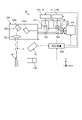
- FIG. 1 is an exemplary schematic configuration diagram of a laser welding device according to an embodiment.
- FIG. 2 is an exemplary schematic plan view showing an example of the shape of a spot of laser light irradiated onto an object from the laser welding apparatus of the embodiment.
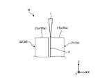
- FIG. 3 is an exemplary and schematic side view of an object before welding in the laser welding method of the embodiment.
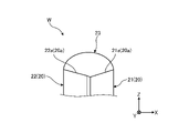
- FIG. 4 is an exemplary and schematic side view after welding of the object in the laser welding method of the embodiment.
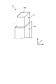
- FIG. 5 is an exemplary and schematic perspective view of a flat wire including a member as an object of the laser welding method of the embodiment.
- FIG. 6 is an exemplary and schematic plan view showing an example of a scanning path at an end portion in the laser welding method of the embodiment.
- FIG. 7 is a graph showing an example of changes in light source output according to the irradiation position in the scanning path in the laser welding method of the embodiment.
- FIG. 8 is an exemplary and schematic plan view showing an example of setting a range in which the light source output set near the edge is relatively low in the laser welding method of the embodiment.
- FIG. 9 is an exemplary schematic plan view showing an example of setting a range in which the light source output is set relatively low in the vicinity of the bent portion in the laser welding method of the embodiment.
- FIG. 10 is an exemplary and schematic plan view showing another example of the scanning path at the end in the laser welding method of the embodiment.
- FIG. 11 is an exemplary and schematic plan view showing another example of the scanning path at the end in the laser welding method of the embodiment.
- FIG. 12 is an exemplary schematic plan view showing a plurality of sections included in the scanning path of FIG. 11.
- FIG. FIG. 13 is a graph showing an example of temporal changes in light source output when scanning is performed in the scanning path of FIG. 11 and the interval of FIG. 12 .
- FIG. 14 is a graph showing another example of temporal changes in light source output when scanning is performed along the scanning path of FIG. 11 and the interval of FIG.
- FIG. 15 is an exemplary and schematic plan view showing still another example of the scanning path at the end in the laser welding method of the embodiment.
- the direction X is represented by an arrow X
- the direction Y is represented by an arrow Y
- the direction Z is represented by an arrow Z.
- Direction X, direction Y, and direction Z intersect and are orthogonal to each other.
- the Z direction is the direction in which the plurality of members that form the object W extend. Although the Z direction is substantially vertically upward, it may be tilted with respect to the vertically upward direction.
- FIG. 1 is a diagram showing a schematic configuration of a laser welding device 100 according to an embodiment.
- the laser welding device 100 includes a laser device 110 (111, 112), an optical head 120, an optical fiber 130, a driving mechanism 140, a sensor 150, and a control device 200. ing.
- the laser welding device 100 irradiates a laser beam L onto the surface of an object W to be laser-welded.
- the object W is partially melted by the energy of the laser beam L, cooled, and solidified, thereby welding the object W.
- the object W has a plurality of members, and by laser welding, a molten pool extending over the plurality of members is formed, and the plurality of members are joined by solidifying the molten pool.
- a plurality of members to be the object W can be made of, for example, a copper-based metal material such as copper or a copper alloy, an aluminum-based metal material such as aluminum or an aluminum alloy, or the like.
- a plurality of members may be made of the same metal material, or may be made of different metal materials. It should be noted that the plurality of members to be the object W may be conductors or may not be conductors.
- Each of the laser devices 111 and 112 has a laser oscillator, and is configured, for example, to output a single-mode laser beam with a power of several kW.
- the laser device 110 may include a plurality of semiconductor laser elements inside, and may be configured to output multimode laser light with a power of several kW as the total output of the plurality of semiconductor laser elements.
- the laser device 110 may also include various laser light sources such as fiber lasers, YAG lasers, disk lasers, and the like. Also, the laser device 110 outputs laser light with a wavelength of 400 [nm] or more and 1200 [nm] or less, for example.
- the laser device 111 outputs a first laser beam with a wavelength of, for example, 800 [nm] or more and 1200 [nm] or less.
- Laser device 111 may also be referred to as a first laser device.
- a laser oscillator included in the laser device 111 is a light source and can also be referred to as a first laser oscillator.
- the laser device 112 outputs a second laser beam with a wavelength of, for example, 300 [nm] or more and 600 [nm] or less.
- Laser device 112 may also be referred to as a second laser device.
- a laser oscillator included in the laser device 112 is a light source and can also be referred to as a second laser oscillator.
- the second laser light has a higher absorptance and a lower reflectance than the first laser light.
- the laser devices 111 and 112 may each output a continuous wave of laser light, or may output a pulse of laser light.
- the control device 200 can control the operation of the laser devices 111 and 112.
- the control device 200 can control the laser devices 111 and 112 to output laser light, stop outputting laser light, and change the output intensity.
- An optical fiber 130 optically connects the laser device 110 and the optical head 120 .
- the optical fiber 130 guides the laser light output from the laser device 110 to the optical head 120 .
- the laser device 110 outputs single-mode laser light
- the optical fiber 130 is configured to propagate the single-mode laser light.
- the M2 beam quality of single-mode laser light is set to 1.3 or less.
- the M2 beam quality may also be referred to as the M2 factor.
- the optical head 120 is an optical device for irradiating the object W with laser light input from the laser device 110 .
- the optical head 120 has a collimator lens 121 , a condenser lens 122 , a filter 123 , a mirror 124 , a DOE 125 and a galvanometer scanner 126 .
- Collimating lens 121, condenser lens 122, filter 123, mirror 124, DOE 125, and galvanometer scanner 126 may also be referred to as optics.
- the collimator lenses 121 collimate the laser beams input via the optical fibers 130 respectively.
- the collimated laser light becomes parallel light.
- the mirror 124 reflects the first laser beam collimated by the collimator lens 121 and directs it to the galvanometer scanner 126 .
- the filter 123 is a high-pass filter that transmits the first laser beam and reflects the second laser beam without transmitting it.
- the first laser light from mirror 124 is transmitted through filter 123 and directed to galvanometer scanner 126 .
- the second laser beam from the collimating lens 121 is reflected by the filter 123 and directed toward the galvanometer scanner 126 .
- the galvanometer scanner 126 has a plurality of mirrors 126a and 126b. By changing the angles of the plurality of mirrors 126a and 126b, it is possible to switch the emission direction of the laser light L from the optical head 120, thereby changing the irradiation position of the laser light L on the surface of the object W. .
- the angles of the mirrors 126a and 126b are respectively changed by motors (not shown) controlled by the controller 200, for example.
- the controller 200 for example.
- the condensing lens 122 condenses the laser light as parallel light coming from the galvanometer scanner 126, and irradiates the object W with the laser light L (output light).
- the DOE 125 shapes the beam of the first laser beam collimated by the collimating lens 121 .
- DOE 125 is an example of a beam shaper.
- the drive mechanism 140 changes the relative position of the optical head 120 with respect to the object W.
- the drive mechanism 140 includes, for example, a rotation mechanism such as a motor, a reduction mechanism that reduces the rotation output of the rotation mechanism, a motion conversion mechanism that converts the rotation reduced by the reduction mechanism into direct motion, and the like.
- the control device 200 can control the driving mechanism 140 so that the relative position of the optical head 120 with respect to the object W in the X, Y and Z directions is changed.
- the drive mechanism 140 can change (switch) the object W to be laser-welded among the plurality of objects W supported by the support mechanism (not shown). Further, the driving mechanism 140 can change the irradiation position of the laser beam L on the object W.
- the driving mechanism 140 can be used to change the irradiation point along with changing the irradiation direction of the laser beam with respect to the object W.
- the driving mechanism 140 can change the irradiation position while the surface of the object W is being irradiated with the laser light L.
- the driving mechanism 140 can scan the laser beam L on the surface of the object W.
- FIG. 2 is a plan view of the spot S formed on the edge 20a of the object W by irradiating the edge 20a with the laser beam L.
- the spot S includes a substantially circular irradiation area IA1 of the beam B1 of the first laser light output from the laser device 111 and a beam B2 of the second laser light output from the laser device 112. and a substantially circular irradiation area IA2 by .
- the irradiation area IA1 is positioned within the irradiation area IA2, and the center of the irradiation area IA1 substantially coincides with the center of the irradiation area IA2.
- the shape of the spot S is not limited to the example of FIG. 2, and the shapes of the irradiation areas IA1 and IA2 are not limited to circular shapes.
- the beam may be shaped by the DOE 125 so that the irradiation area IA1 includes a plurality of small areas arranged in a ring or matrix, for example. If the beam shape of the first laser beam output from the laser device 111 can be appropriately set by the DOE 125, the output of the second laser beam from the laser device 112 may be unnecessary.
- At least a part of the irradiation area IA2 should be located in front of the irradiation area IA1 in the scanning direction, and the center of the irradiation area IA1 and the center of the irradiation area IA2 are displaced from each other. good too.
- FIG. 3 is a side view showing the state of the object W before welding.
- the object W has two members 20 (21, 22). Both of the two members 20 are made of metal material. Examples of the object W shown in FIG. 3 include, for example, an example in which windings of an electromagnetic coil used in a motor of a vehicle are welded and connected to each other.
- Both of the two members 20 extend in the Z direction and have ends 20a (21a, 22a) in the Z direction.
- the end portion 20a spreads across the Z direction. That is, the end portion 20a extends in the X direction and in the Y direction.
- the Z direction is an example of a first direction.
- the end 21a is an example of a first end, and the end 22a is an example of a second end.
- the two members 20 Prior to welding, the two members 20 are arranged so as to be adjacent to each other in the X direction that intersects the Z direction and to line up in the X direction.
- a gap g is formed between the side surfaces facing each other in the X direction.
- the size of the gap g is 0 or more. That is, the two members 20 may be at least partially in contact.
- the X direction is an example of the second direction.
- the ends 21a and 22a are aligned in the X direction and are positioned at the same position in the Z direction. It may be shifted in the Z direction.
- the optical head 120 irradiates the laser beam L toward the end portion 20a.
- the irradiation direction of the laser light L is the direction opposite to the Z direction or the direction inclined with respect to the direction opposite to the Z direction.
- the laser beam L may be applied to both the end portion 21a and the end portion 22a, or may be applied to only one of the end portion 21a and the end portion 22a.
- FIG. 4 is a side view showing a state in which the welded portion 23 (molten pool) is formed on the object W.
- the two members 20 are melted at the end portion 20a, and a welded portion 23 is formed in a state in which the two end portions 20a are spanned. be.
- the welded portion 23 is formed by cooling and solidifying a molten pool formed in a state of being bridged between the two ends 20a.
- a molten pool which is a metal material having fluidity, has a shape that bulges in the Z direction due to surface tension.
- the welded portion 23 formed by solidifying the molten pool also has a bulging shape in the Z direction.
- the weld 23 mechanically connects the two members 21 and 22 .
- the welded portion 23 electrically connects the two members 21 and 22 .
- the sensor 150 (see FIG. 1) is, for example, a camera that captures the molten pool formed on the object W.
- sensor 150 is an example of a motion sensor.
- the control device 200 can acquire the movement (change over time) of the surface of the molten pool from the images acquired by the sensor 150 .
- the senor 150 may be a thermal camera capable of detecting the temperature of the molten pool.
- sensor 150 is an example of a temperature sensor.
- the control device 200 can acquire the temperature of the molten pool from the temperature image acquired by the sensor 150 .
- FIG. 5 is a perspective view of the flat wire 10 including the member 20.
- the member 20 is, for example, a core wire (inner conductor) of a rectangular wire 10 as shown in FIG.
- the rectangular wire 10 has a member 20 and a covering 30 of the member 20 .
- the member 20 is made of a conductive metal material.
- the shape of the cross section of the member 20 perpendicular to the extending direction is substantially rectangular.
- the coating 30 has insulating properties and is made of, for example, enamel or a synthetic resin material.
- the coating 30 may have an enamel layer and an extruded resin layer surrounding the enamel layer.
- the laser welding apparatus 100 is applied to welding the end portions 20a of the member 20 as the core wire of the rectangular wire 10 as described above.
- the coating 30 is removed in the vicinity of the ends of the two rectangular wires 10 in the extending direction. Then, as shown in FIG. 3 , the laser welding device 100 welds the end portions 20a of the two members 20 arranged so as to face each other in the same direction (extending direction).
- the rectangular wire 10 may constitute a segment coil provided in rotating electricity.
- the laser welding method by the laser welding apparatus 100 of this embodiment can be applied to welding the ends of adjacent segment coils set on the stator core.
- the member 20 that becomes the object W is not limited to the core wire of the rectangular wire 10, and may be members that extend in the Z direction and are adjacent to each other in the X direction, as shown in FIG. Further, the member 20 may be a plate-like member or a wire rod.
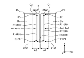
- FIG. 6 is a plan view showing an example of the scanning route R1 of the laser light L at the ends 21a and 22a. As shown in FIG. 6, in this embodiment, the laser light L is scanned along a scanning path R1 in a direction intersecting the Z direction.
- each of the end portion 21a and the end portion 22a has a rectangular shape. and has a rectangular shape that is relatively short in the X direction and relatively long in the Y direction.
- the Y direction can be referred to as the longitudinal direction and the X direction can be referred to as the lateral direction.
- the end portion 21a and the end portion 22a have the same shape, but the present invention is not limited to this.
- the laser light L is directed to an area A1 closer to the end 22a than the center C1 of the end 21a in the X direction and to the end 21a more than the center C2 of the end 22a in the X direction. are scanned in the near area A2 and .
- the scanning route R1 has sections R11, R12, R13, R14, and R15.
- the scanning route R1 is a continuous linear route connecting from the irradiation start point (irradiation position P1) to the irradiation end point (irradiation position P6).
- the end portions 21a and 22a It has been found that the temperature difference (temperature variation) depending on the location of the (molten pool) can be made smaller, and a more stable molten pool can be formed.
- the irradiation start point may also be referred to as a scan start position
- the irradiation end point may also be referred to as a scan end position.
- a section R11 is a section from the irradiation position P1 to the irradiation position P2, and a section R12 is a section from the irradiation position P2 to the irradiation position P3.
- the section R11 and the section R12 are shown shifted in the X direction for the sake of clarity. It is the same position as P3.
- the irradiation position P1 is the irradiation start point.
- the irradiation position P1 is located near the edge 21a1 opposite to the Y direction of the end 21a. Further, the irradiation position P2 is positioned near the Y-direction edge 21a2 of the end portion 21a.
- the laser beam L is scanned from the irradiation position P1 to the irradiation position P2 in a section R11 linearly extending in the Y direction, that is, in the longitudinal direction of the end portion 21a.
- the laser beam L scanned in the section R11 is bent in the opposite direction at the irradiation position P2 located at the end of the section R11, that is, folded back, and linearly extends in the opposite direction of the Y direction from the irradiation position P2 to the irradiation position P3. Scanning is performed in section R12.
- section R11 is an example of a first section
- section R12 is an example of a second section
- irradiation position P2 is an example of a bent portion.
- the section from section R11 to section R12 is an example of the bending scanning section.
- the angle change amount at the irradiation position P2 as the bending portion of the bending scanning section is 180°. In this specification, the angle change amount is set to a value of 180° or less.
- a section R13 is a section from the irradiation position P3 to the irradiation position P4.
- the irradiation position P4 is located near the edge 22a2 of the end portion 22a opposite to the Y direction.
- the laser beam L scanned in the section R12 is bent 90° at the irradiation position P3 located at the end of the section R12, and extends from the irradiation position P3 to the irradiation position P4 in the opposite direction of the X direction, i.e., the short sides of the ends 21a and 22a. Scanning is performed in a section R13 linearly extending in the direction. From section R12 to section R13, section R12 is an example of a first section, section R13 is an example of a second section, and irradiation position P3 is an example of a bending portion. Also, the section from section R12 to section R13 is an example of the bending scanning section. The angle change amount at the irradiation position P3 as the bending portion of the bending scanning section is 90°.
- a section R14 is a section from the irradiation position P4 to the irradiation position P5, and a section R15 is a section from the irradiation position P5 to the irradiation position P6.
- the section R14 and the section R15 are shown shifted in the X direction. It is the same position as P6.
- the irradiation position P5 is located near the Y-direction edge 22a2 of the end portion 22a. Further, the irradiation position P6 is the irradiation end point.
- the laser beam L scanned in the section R13 is bent 90° at the irradiation position P4 located at the end of the section R13, and extends linearly in the Y direction, that is, the longitudinal direction of the end portion 22a, from the irradiation position P4 to the irradiation position P5. Scanning is performed in the interval R14.
- section R13 is an example of a first section
- section R14 is an example of a second section
- irradiation position P4 is an example of a bent portion.
- the section from section R13 to section R14 is an example of the bending scanning section.
- the angle change amount at the irradiation position P4 as the bent portion of the bent scanning section is 90°.
- the laser beam L scanned in the section R14 is bent in the opposite direction at the irradiation position P5 located at the end of the section R14, that is, folded back, and linearly extends in the opposite direction of the Y direction from the irradiation position P5 to the irradiation position P6. Scanning is performed in section R15. From section R14 to section R15, section R14 is an example of a first section, section R15 is an example of a second section, and irradiation position P5 is an example of a bent portion. Also, the section from section R14 to section R15 is an example of the bending scanning section. The angle change amount at the irradiation position P5 as the bending portion of the bending scanning section is 180°.
- the sections R11, R12, R14, and R15 include irradiation positions farther from the edges 21a1, 21a2, 22a1, and 22a2 than the irradiation positions P1 to P6 as the ends of the sections. I'm in.
- the irradiation positions P1 to P6 are examples of irradiation ends.
- the inventors performed welding by scanning the laser beam L along the scanning path R1 in FIG.
- the first laser light having a wavelength of 1070 [nm] and , and a second laser beam having a wavelength of 450 [nm].
- a circular spot (beam) of the first laser light and a circular spot (beam) of the second laser light are concentrically arranged on a plane intersecting the Z direction of the ends 21a and 22a, and the end 21a , 22a, the diameter of the spot of the first laser beam is about 15 [ ⁇ m], and the diameter of the spot of the second laser beam is about 230 [ ⁇ m].
- the diameter of the spot can be defined as the diameter of the region including the peak of the beam and having an intensity of 1/e 2 or more of the peak intensity.
- the beam diameter can be defined as the length of the region where the intensity is 1/e2 or more of the peak intensity in the direction perpendicular to the scanning direction.
- the power distribution in the spot is not limited to a Gaussian shape.
- the scanning speed of the laser light L was kept constant at 80 [mm/s].
- the inventors conducted an experiment under the conditions described above, and found that at irradiation positions near the edges 21a1, 21a2, 22a1, 22a2 in the longitudinal direction, such as the irradiation positions P1 to P6, the edges 21a1, 21a2, 22a1, 22a1, 21a2, 22a2 It was found that the frequency of spattering is higher than that at irradiation positions farther from 22a2. This is because, in places near the edges 21a1, 21a2, 22a1, and 22a2 in the longitudinal direction, there is less metal material in the periphery than in the middle position in the longitudinal direction, so that heat tends to accumulate, and the temperature of the molten pool rises. It is presumed that the occurrence frequency of spatter is increasing.
- the inventors conducted repeated experiments and found that by appropriately changing the irradiation position of the output of the laser light, an excessive rise in the temperature of the molten pool can be suppressed. We have found that it is possible to achieve a suitable weld that is less prone to spillage.
- FIG. 7 shows the light source output (power) of the first laser light on the scanning route R1 from the irradiation position P1 to the irradiation position P6, that is, the output of the laser light from the laser device 111, depending on the irradiation position in the scanning route R1. It is a graph which shows an example of a change. Note that the output of the second laser light was constant at 150 [W].
- the light source outputs at intermediate positions Pm1, Pm2, Pm4 and Pm5 farther from the edges 21a1, 21a2, 22a1 and 22a2 , R14 and R15, and is set higher than the light source output at the irradiation positions P1, P2, P4, P5 and P6 closer to the edges 21a1, 21a2, 22a1 and 22a2.
- the scanning path R1 is bent or turned back at the irradiation positions P2 to P5.
- the time for which the spot of the laser beam stays in a relatively close range becomes longer, and regardless of the distance from the edges 21a1, 21a2, 22a1, and 22a2, It has been found that the temperature of the molten pool tends to rise more easily than in the section where the laser beam spot moves linearly without bending or folding back, which may increase the frequency of spatter generation.
- the larger the angle change amount at the bending portion of the bending scanning section described above the easier it is for the spot of the laser beam to stay at a closer position, so the temperature of the molten pool tends to rise. Therefore, the temperature rise of the molten pool can be suppressed by lowering the light source output at the bent portion as the angle change amount increases.
- the angle change amount increases.
- the temporary light source output drop amount D1 when passing through the irradiation position P2 as the bent portion in the bent scanning section where the angle change amount is 180° from the section R11 to the section R12 is It is larger than the temporary light source output decrease amount D2 when passing through the irradiation position P3 as the bent portion in the bent scanning section from the section R12 to the section R13 where the angle change amount is 90°.
- the light source output gradually and linearly changes in each of the sections R11, R12, R14, and R15.
- the setting may be such that the light source output is lowered within a range in which the light source becomes easier to light.
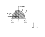
- FIG. 8 shows a range S3 (hatched area) in which the light source output is relatively low set near the edge 21a2 and the irradiation position P2, and a range S3 in which the light source output is relatively high outside the range S3. It is a top view which shows an example of range S4.
- Range S3 is an example of the third range and the predetermined region, and can also be referred to as an edge region.
- Range S4 is an example of the fourth range and other predetermined regions. In this way, the light source at the irradiation position included in the range (third range) within a predetermined distance from the irradiation positions P1 to P6 near the edges 21a1, 21a2, 22a1, 22a2 or the edges 21a1, 21a2, 22a1, 22a2.
- the output (power) is lower than the light source output at the irradiation position included in the range (fourth range) outside the range, or the irradiation position is the center of the members 21 and 22 in the Y direction, for example, 80 [ %], for example, it is possible to suppress the occurrence of spatter in the range S3, and to suppress the spillage of the molten pool.
- the width of the range S3 in the Y direction is preferably 2.4 [mm] or less, more preferably 1.8 [mm] or less.
- the ratio of the Y-direction width of the range S3 to the Y-direction dimension of the member 21 is 0. It is preferably 8 or less, more preferably 0.6 or less.
- FIG. 9 shows a range S1 (hatched area) in which the light source output is relatively low within a predetermined distance centering on the irradiation position P3 as the bent portion, and the light source output outside the range S1. It is a top view which shows an example of range S2 made relatively high. Range S1 is an example of the first range and the predetermined area, and range S2 is an example of the second range and another predetermined area.
- the light source output (power) at the irradiation position included in the range (first range) within a predetermined distance from the irradiation positions P2 to P5 as the bending portion is changed to the range outside the range (second range)
- the light source output lower than that at the irradiation positions included in , there is an advantage that the generation of spatter in the range S1 can be suppressed, for example.
- the bent portion is formed when the scanning direction of the laser beam changes by a predetermined angle (eg, 45 degrees) or more, and the radius of curvature of the scanning trajectory of the laser beam is a predetermined value (eg, 1.0 mm) or less. can be defined as the region where
- the lower the scanning speed the lower the light source output.
- the higher the light source output the higher the scanning speed.
- the light source output may be lowered, more preferably by 50% or more.
- the predetermined value is half the original scanning speed and can also be referred to as the threshold speed. According to such a setting, it is possible to suppress an increase in irradiation energy density due to an increase in light source output by increasing the scanning speed.
- the scanning speed is an example of the irradiation state of the laser light.
- the area of the cross section of the object W perpendicular to the irradiation direction of the laser beam is 30 [mm 2 ] or less, more preferably 20 [mm 2 ] or less, and still more preferably 10 [mm 2 ] or less, This is preferable because the frequency of spatter generation can be increased and the molten pool can be prevented from falling off the ends 21a and 22a.
- the rate of increase in temperature of the end portions 21a and 22a is slower than after the start of scanning.
- the light source output of the first laser beam is increased, a keyhole is generated and the temperature rises locally, making the molten pool unstable and possibly generating spatter. Therefore, the light source output of the second laser beam at the irradiation position P1 may be set higher than the light source output of the second laser beam after the start of scanning.
- the temperature of the end portions 21a and 22a can be raised more gently by the irradiation of the second laser beam having a higher absorptivity, and the molten pool can be formed more stably, which in turn reduces the sputtering. The occurrence can be suppressed.
- control device 200 acquires the movement amount (amplitude) of the surface of the molten pool from the image acquired by the sensor 150, and when the movement amount becomes large, the laser beam L is adjusted so that the irradiation energy density becomes low. , or the scanning speed of the laser beam L may be increased.
- the control device 200 controls the laser device 110 to lower the light source output when the movement amount exceeds a threshold value, or to lower the light source output as the movement amount increases. be able to.
- the control device can increase the scanning speed when the amount of movement exceeds a threshold value, or increase the scanning speed as the amount of movement increases. . According to such control, the molten pool can be more stabilized, and the occurrence of spatter can be suppressed.
- the control device 200 acquires the temperature of the molten pool from the image acquired by the sensor 150, and based on the temperature of the molten pool, for example, according to the irradiation position, the temperature of the molten pool is within a predetermined range. It is possible to control the irradiation state of the laser light, that is, the light source output and the scanning speed. Specifically, for example, by controlling the laser device 110, the control device 200 can lower the light source output when the temperature exceeds a threshold value, or lower the light source output as the temperature rises. can. Further, by controlling the galvanometer scanner 126 and the driving mechanism 140, the control device can increase the scanning speed when the temperature exceeds the threshold value, or increase the scanning speed as the temperature increases.
- the molten pool can be more stabilized, and the occurrence of spatter can be suppressed.
- the sensor 150 may detect the state of radiation emitted from the molten pool.
- the state of the emitted light that can be detected by the sensor 150 and that changes according to the temperature of the molten pool includes, for example, the intensity and wavelength.
- the control device 200 acquires the temperature of the molten pool from the detected value of the sensor 150 based on the correlation between the detected value and the temperature, and adjusts the temperature of the molten pool to the irradiation position, for example, so that the temperature of the molten pool falls within a predetermined range.
- the irradiation state of the laser light that is, the light source output and the scanning speed can be controlled accordingly.
- FIG. 10 is a plan view showing an example of the scanning route R2 of the laser light L at the ends 21a and 22a.
- the laser beam L is scanned along the scanning path R2 in the direction crossing the Z direction.
- the scanning route R2 includes a section R21 extending in the Y direction from an irradiation position P1 near the edge 21a1 on the end portion 21a to an irradiation position P2 near the edge 21a2, and an irradiation position from the irradiation position P2 to an irradiation position near the edge 22a2 on the end portion 22a.
- a section R24 extending in the X direction up to the position P4 is included.
- irradiation positions P2, P3, and P4 are bending portions with an angle change amount of 90°.
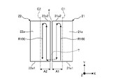
- FIG. 11 is a plan view showing an example of the scanning route R100 of the laser light L at the ends 21a and 22a.
- the spot S (see FIG. 2) of the laser beam L moves (is scanned) along the scanning route R100 in the direction intersecting the Z direction.
- a scanning route R100 indicates the locus of movement of the center of the spot S.
- the laser light L is scanned in a substantially U shape on the end portion 21a, and then scanned in a substantially U shape on the end portion 22a.
- scanning path R100 is set within areas A1 and A2.
- the shape of the scanning route R100 on the end portion 21a and the shape of the scanning route R100 on the end portion 22a are substantially the same. Further, the laser light L is not emitted from the optical head 120 on the movement path T between the end portions 21a and 22a.
- FIG. 12 is a plan view of the scanning route R100 of the laser light L at each end 21a, 22a. 12, the scanning path R100 is drawn with a width for the sake of clarity, but the width of the scanning path R100 in FIG. 12 is irrelevant to the size of the spot S.
- the scanning route R100 includes sections R101 to R109 in this order.
- the spot S moves linearly in the Y direction in the sections R101 to R105.
- section R106 the spot S moves while curving in a substantially U-shape that opens in the opposite direction of the Y direction.
- the spot S moves linearly in the direction opposite to the Y direction in the sections R107 to R109.
- sections R101 to R105 and sections R107 to R109 are examples of linear scanning sections
- section R106 is an example of non-linear scanning sections.
- Sections R101 to R105 are an example of a first section
- sections R107 to R109 are an example of a second section.
- sections R101 to R105 and sections R107 to R109 are separated from each other in the X direction, section R106 is smoothly connected to these sections R101 to R105 and sections R107 to R109, and has a predetermined radius.
- curved at The radius of curvature of section R106 is half the distance in the X direction of sections R101-R105 and sections R107-R109.
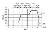
- FIG. 13 is a graph showing an example of temporal changes in the light source output (power) in the scanning path R100 shown in FIG. 12 at each end 21a, 22a.
- the solid line indicates the total output value of the laser device 111 that outputs the first laser light forming the beam B1, and the total output value of the laser device 112 that outputs the second laser light forming the beam B2. is indicated by a solid line.
- the light source output corresponding to beam B2 is constant between sections R101 to R109.
- the light source output corresponding to beam B1 is 0 in section R101, is constant in sections R104 and R108, and changes with time in sections R102, R103, R105, R107 and R109.
- sections R101, R104, and R108 are examples of constant power sections in which the irradiation position (spot S) moves while the power of the laser light L emitted from the optical head 120 is constant.
- Sections R102, R103, and R107 are examples of power increase sections in which the irradiation position (spot S) moves while the power of the laser light L emitted from the optical head 120 increases over time. is an example.
- Sections R105 and R109 are examples of power reduction sections in which the irradiation position (spot S) moves while the power of the laser light L emitted from the optical head 120 decreases over time.
- the light source output in the section R106 is set to be lower than the light source output in the sections R104 and R108 before and after it, for example, 80% or less. This is because the spot S of the laser beam L stays relatively close during movement in a non-linear scanning section such as a curved section like section R106 or a crooked (bent) section (not shown). , the irradiation energy density tends to be high. Therefore, as in the example of FIG.
- the other sections R101 to It suppresses the irradiation energy density from becoming higher than R105, R107 to R109, reduces the difference (variation) in the irradiation energy density depending on the location of the end portions 21a and 22a, and eventually spatters due to excessive temperature rise of the molten pool. , it is possible to suppress the spillage of the molten pool.
- sections R102, R103, and R107 in which the light source output increases with time, it is possible to suppress the occurrence of spatter due to an excessive temperature rise of the molten pool and the spillage of the molten pool.
- the increase over time may be a gradual increase or a stepwise increase.
- the sections where the light source output decreases with time such as sections R105 and R109, the formation of voids due to an increase in movement of the molten pool, such as disappearance of keyholes due to a rapid temperature drop of the molten pool. It is possible to suppress the occurrence of contamination and the occurrence of spatter.
- the decrease over time may be a gradual decrease or a stepwise decrease.
- the power increase rate or decrease rate (change rate) in sections R102, R103, R105, R107, and R109 can be appropriately set so that the state of the molten pool becomes moderate.
- the rate of decrease (rate of change) may be changed over time.
- the light source output in section R104 that is, the maximum value of the light source output in sections R101 to R105 in which the spot S moves in the Y direction
- the light source output in section R108 that is, the spot S moves in the Y direction.
- the maximum value of the light source output in the section R107 to R109 moving in the opposite direction is the same. In this case, for example, more energy can be supplied in a shorter time, so the processing time can be shortened, or the operation of the laser devices 111 and 112 can be managed more easily. You get the advantage.
- the second laser light has a relatively high absorption rate in the material, it has a short wavelength and relatively low convergence, so it is difficult to efficiently apply energy.
- the first laser light has a relatively low absorptivity in the material, but has a long wavelength and relatively high convergence, so it is easy to apply energy to the object W more efficiently. Therefore, by irradiating the second laser beam, the object W is preliminarily heated in a stage before the irradiation of the first laser beam, and by irradiating the first laser beam, the energy for melting the object W is input. Therefore, the object W can be melted more efficiently while suppressing rapid temperature changes of the object W.
- the beam B1 of the first laser light is irradiated from a stage before the irradiation. It is preferable to irradiate only the beam B2 of two laser beams.
- the irradiation start position Ps0 of the second laser light and the irradiation start position Ps1 of the first laser light are different from each other.
- the irradiation end position Pe of the first laser beam and the second laser beam in the Y direction corresponds to the irradiation start position Ps0 of the second laser beam in the Y direction and the irradiation start position Ps0 of the first laser beam in the Y direction.
- it is different from both of the start positions Ps1 it is not limited to this, and their relative positional relationship can be appropriately set so that the state of the molten pool becomes moderate.
- the second laser light may be irradiated at a fixed point without scanning for a certain period of time at the start of irradiation.
- the temperature of the object W can be raised to an appropriate temperature more quickly, and the object W can be processed more efficiently.
- the light source output of the second laser beam is set substantially constant over time as in the example of FIG. It is preferable to change the light source output of the first laser light over time.
- FIG. 14 is a graph showing another example of temporal changes in the light source output (power) in the scanning path R100 shown in FIG. 12 at each end 21a, 22a.
- the solid line indicates the total output value of the laser device 111 that outputs the first laser light forming the beam B1, and the total output value of the laser device 112 that outputs the second laser light forming the beam B2. is indicated by a solid line.
- the light source output in section R104 is set lower than the light source output in section R108.
- Experimental research by the inventors has revealed that, in sections R102 and R103, when the light source output of the laser device 111 suddenly rises from a low state, the molten pool moves violently and spatters are likely to occur in some cases. Therefore, in the example of FIG. 14, the light source output in section R104 is set lower than the light source output in section R108.
- the maximum value of the light source output in the section R101 to R105 is set lower than the maximum value of the light source output in the section R107 to R109.
- the value of the light source output in section R104 is set to the same value as the light source output in section R106 in the example of FIG. 14, but is not limited to this.
- the setting can be appropriately changed, such as setting the light source output to be lower than that of the section R108.
- an increase in light source output may be appropriately replaced with a decrease in scanning speed, and a decrease in light source output may be appropriately replaced with an increase in scanning speed.
- FIG. 15 is a plan view showing an example of the scanning route R100 of the laser light L at the ends 21a and 22a.
- the laser light L scans the ends 21a and 22a in a substantially U shape.
- the laser light L is at least partially distributed from regions outside the regions A1 and A2, that is, from the X-direction centers C1 and C2 of one of the ends 21a and 22a. are also scanned in regions far from the other end. Even when the laser beam L is scanned along the scanning path R100, the required welded portion 23 can be formed, and the generation of spatter due to an excessive temperature rise of the molten pool and the spillage of the molten pool can be suppressed.
- the required welded portion 23 can be formed, and the generation of spatter due to an excessive temperature rise of the molten pool and the spillage of the molten pool can be suppressed.
- the present embodiment in order to reduce the difference in the irradiation energy density of the laser light depending on the location in the regions irradiated with the laser light at the end portions 21a and 22a, The irradiation state of laser light can be changed. As a result, it is possible to suppress an excessive rise in the temperature of the molten pool, which leads to various effects such as suppressing the occurrence of spatter and suppressing spillage due to excessive growth of the molten pool.
- the object was a rectangular wire, but the object is not limited to this, and may be other conducting wires or other metal members. Also, the object may include three or more members. Also, the plurality of members included in the target object may not be the same member. Moreover, the target object is not limited to a plurality of members arranged side by side or butted against each other, and may be a plurality of superimposed members.
- known wobbling, weaving, output modulation, etc. may be performed to adjust the surface area of the molten pool.
- the position to be scanned that is, the irradiation area and the scanning path are not limited to the above examples, and can be set in various ways.
- the present invention can be implemented in the following modes.
- (21) In the laser welding method of the present invention, in at least a part of the power change section, even if the power increase rate or power decrease rate of the irradiated laser light changes over time according to the movement of the irradiation position of the laser light. good.
- (22) In the laser welding method, in the step of irradiating the laser beam, when a predetermined region of the first end portion or the second end portion is irradiated with the laser beam, another predetermined region is irradiated with the laser beam.
- the laser light may be applied at a lower output than in the case.
- the predetermined area may include a bent portion in the scanning path of the laser beam, and the other predetermined area may be an area other than the predetermined area.
- the predetermined region may be an edge region of the first end, and the other predetermined region may be a region other than the edge region of the first end.
- the predetermined region may be an edge region of the first end, and the other predetermined region may include a center of the first end in the predetermined direction.
- the scanning speed of the laser beam at the first end portion or the second end portion may be changed according to the irradiation position of the laser beam.
- the lower the scanning speed of the laser light at the first end portion or the second end portion the lower the power of the laser light to be irradiated.
- the power of the laser light to be irradiated is increased as the radius of curvature of the scanning path of the laser light at the first end or the second end is increased, or A lower scanning speed may be used.
- the scanning path of the irradiation position of the laser beam at the first end or the second end is linearly scanned; a second section which is bent at a bending portion located at the end of one section and linearly scanned in a direction different from the scanning direction of the first section; and the first section, the second section, or the bending section.
- laser light that is outside the first range and emits laser light with a power higher than that of the first range.
- the scanning path of the irradiation position of the laser beam at the first end or the second end is linearly scanned; a second section that is bent at a bending portion positioned at the end of one section and linearly scanned in a direction different from the scanning direction of the first section, from the first section toward the second section;
- a plurality of different bending scanning sections may be provided, and in the plurality of bending scanning sections, the larger the angular change amount, the larger the temporary power reduction amount.
- the scanning path of the irradiation position of the laser beam at the first end portion or the second end portion is the edge of the first end portion or the second end portion.
- a fourth section including an irradiation end close to an edge and an irradiation position farther from the edge than the irradiation end, and in the fourth section, the closer the irradiation position is to the irradiation end, the lower the Laser light may be applied with high power.
- the scanning path of the irradiation position of the laser beam at the first end portion or the second end portion is the edge of the first end portion or the second end portion.
- a fourth section including an irradiation end close to an edge and an irradiation position farther from the edge than the irradiation end, and from the edge or the irradiation end in the fourth section or the irradiation end It may include a third range within a predetermined distance, and a fourth range outside the third range in the fourth section, in which laser light is irradiated with a power higher than that of the third range.
- the second laser beam in the step of irradiating the laser beam, may be irradiated at the scanning start position with a power higher than that at the irradiation position after the scanning is started.
- the temperature of the molten pool is detected in the step of irradiating the laser beam, and the laser beam is emitted according to the irradiation position of the laser beam so that the higher the temperature of the molten pool, the lower the irradiation energy density. You may change the irradiation state.
- the laser welding method in the step of irradiating the laser beam, the movement of the molten pool is detected, and the laser beam is emitted according to the irradiation position of the laser beam so that the larger the movement of the molten pool, the lower the irradiation energy density. You may change the irradiation state.
- metal materials of the first member and the second member may be either copper-based metal or aluminum-based metal, respectively.
- the metallic material of the first member and the second member may be a conductive material.
- a laser welding method of the present invention is a laser welding method for laser welding a first member made of a metallic material and a second member made of a metallic material, wherein the first member and the second member are A step of irradiating at least one with a laser beam while scanning, and a step of solidifying a molten pool formed over the first member and the second member in the step of irradiating the laser beam,
- the irradiation state of the laser light may be changed according to the irradiation position of the laser light based on the temperature of the molten pool or the state of the radiant light output from the molten pool.
- the present invention can be used for laser welding methods and laser welding devices.
- Section (first section, linear scanning section, constant power section) R102... section (first section, linear scanning section, power change section, power increase section) R103 ... section (first section, linear scanning section, power change section, power increase section) R104 ... section (first section, linear scanning section, constant power section) R105... Sections (first section, linear scanning section, power change section, power decrease section, power constant section) R106... section (non-linear scanning section, constant power section) R107 ... section (second section, linear scanning section, power change section, power increase section) R108 ... section (second section, linear scanning section, constant power section) R109 ... section (second section, linear scanning section, power change section, power increase section) S... Spot S1... Range (first range) S2... range (second range) S3 ... range (third range) S4 ... range (fourth range) T... movement path W... object X... direction (second direction) Y... direction (third direction) Z direction (first direction)
Landscapes
- Physics & Mathematics (AREA)
- Optics & Photonics (AREA)
- Engineering & Computer Science (AREA)
- Plasma & Fusion (AREA)
- Mechanical Engineering (AREA)
- Laser Beam Processing (AREA)
Abstract
金属材料で作られた第一部材の第一方向の第一端部と、金属材料で作られた第二部材の第一方向の第二端部と、をレーザ溶接するレーザ溶接方法であって、第一端部および第二端部を第一方向と交差した第二方向に隣り合うように配置する工程と、第一端部および第二端部のうち少なくとも一方に、第一方向と交差した方向に走査しながらレーザ光を照射する工程と、レーザ光を照射する工程において第一端部と第二端部との間で掛け渡された状態で形成された溶融池を固化する工程と、を備え、レーザ光を照射する工程では、第一端部または第二端部のレーザ光を照射する領域において、レーザ光の照射位置に応じてレーザ光の照射状態を変更する。
Description
本発明は、レーザ溶接方法およびレーザ溶接装置に関する。
平角線のような複数の金属部材をレーザ溶接する方法が知られている(例えば、特許文献1)。
この種の溶接においてスパッタが生じると、例えば、溶接金属内にボイドが発生したり、周囲に残渣が付着したり、当該残渣によって周囲に不要な電気回路が形成されたりといった問題が生じる虞がある。
そこで、本発明の課題の一つは、例えば、スパッタの発生を抑制することを可能とするような、改善された新規なレーザ溶接方法およびレーザ溶接装置を得ること、である。
本発明のレーザ溶接方法は、例えば、金属材料で作られた第一部材の第一方向の第一端部と、金属材料で作られた第二部材の前記第一方向の第二端部と、をレーザ溶接するレーザ溶接方法であって、前記第一端部および前記第二端部を前記第一方向と交差した第二方向に隣り合うように配置する工程と、前記第一端部および前記第二端部のうち少なくとも一方に、前記第一方向と交差した所定の方向に走査しながらレーザ光を照射する工程と、前記レーザ光を照射する工程において前記第一端部と前記第二端部との間で掛け渡された状態で形成された溶融池を固化する工程と、を備え、前記レーザ光を照射する工程では、前記第一端部または前記第二端部のレーザ光を照射する領域において、レーザ光の照射位置に応じてレーザ光の照射状態を変更する。
前記レーザ溶接方法では、前記レーザ光を照射する工程において、レーザ光の照射位置に応じて照射するレーザ光のパワーを変更してもよい。
前記レーザ溶接方法では、前記レーザ光を照射する工程において、前記第一端部または前記第二端部におけるレーザ光の照射位置の走査経路が、直線状に走査される線状走査区間と、湾曲または屈曲して走査される非線状走査区間と、を含み、前記非線状走査区間において、前記線状走査区間の少なくとも一部に対して照射するレーザ光のパワーより低いパワーでレーザ光を照射してもよい。
前記レーザ溶接方法では、前記線状走査区間は、第一区間と、当該第一区間とは逆方向に走査される第二区間と、を含み、前記第一区間において照射されるレーザ光のパワーの最大値と、前記第二区間において照射されるレーザ光のパワーの最大値と、が同じであってもよい。
前記レーザ溶接方法では、前記線状走査区間は、第一区間と、当該第一区間とは逆方向に走査される第二区間と、を含み、前記第一区間において照射されるレーザ光のパワーの最大値と、前記第二区間において照射されるレーザ光のパワーの最大値と、が互いに異なってもよい。
前記レーザ溶接方法では、前記第二区間は、前記第一区間の後に走査される区間であり、前記第二区間において照射されるレーザ光のパワーの最大値が、前記第一区間において照射されるレーザ光のパワーの最大値より大きくてもよい。
前記レーザ溶接方法では、前記第二区間は、前記第一区間の後に走査される区間であり、前記第一区間と前記第二区間との間に、前記非線状走査区間を含み、前記第一区間と前記第二区間とが互いに離れてもよい。
前記レーザ溶接方法では、前記レーザ光を照射する工程において、前記第一端部または前記第二端部におけるレーザ光の照射位置の走査経路が、レーザ光の移動に伴って照射するレーザ光のパワーを経時的に変更するパワー変更区間を含んでもよい。
前記レーザ溶接方法では、前記レーザ光を照射する工程において、前記第一端部または前記第二端部におけるレーザ光の照射位置の走査経路が、照射するレーザ光のパワーが一定の状態で照射位置が移動するパワー一定区間を含んでもよい。
前記レーザ溶接方法では、前記走査経路が、前記パワー変更区間として、レーザ光の走査開始直後においてレーザ光の照射位置の移動に伴って照射するレーザ光のパワーを経時的に増大するパワー増加区間を含んでもよい。
前記レーザ溶接方法では、前記走査経路が、前記パワー変更区間として、レーザ光の走査終了直前においてレーザ光の照射位置の移動に伴って照射するレーザ光のパワーを経時的に減少するパワー減少区間を含んでもよい。
前記レーザ溶接方法では、前記レーザ光を照射する工程において、前記第一端部または前記第二端部におけるレーザ光の照射位置の走査経路が、直線状に走査される第一区間と、当該第一区間の端に位置した折曲部で折れ曲がり前記第一区間の走査方向とは異なる方向に直線状に走査される第二区間と、を含み、前記第一区間および前記第二区間のうち少なくとも一方が、前記照射位置が前記折曲部に近いほどより低いパワーでレーザ光を照射する第三区間を含んでもよい。
前記レーザ溶接方法では、前記レーザ光を照射する工程では、前記第一端部または前記第二端部のレーザ光を照射する領域において、場所によるレーザ光の照射エネルギ密度の差が小さくなるよう、レーザ光の照射位置に応じてレーザ光の照射状態を変更してもよい。
前記レーザ溶接方法では、前記レーザ光は、第一レーザ光と、前記第一端部または前記第二端部の金属材料に対する吸収率が前記第一レーザ光より高い波長の第二レーザ光と、を含んでもよい。
前記レーザ溶接方法では、前記レーザ光を照射する工程において、前記第一レーザ光のパワーを経時的に変更し、前記第二レーザ光のパワーを経時的に略一定としてもよい。
前記レーザ溶接方法では、前記レーザ光を照射する工程において、前記第一端部または前記第二端部におけるレーザ光の照射位置の走査経路が、前記第一レーザ光の照射を開始する前に、前記第二レーザ光のみを照射しながら走査する区間を含んでもよい。
また、本発明のレーザ溶接方法は、例えば、金属材料で作られた第一部材と金属材料で作られた第二部材とをレーザ溶接するレーザ溶接方法であって、前記第一部材および前記第二部材のうち少なくとも一方に、レーザ光を走査しながら照射する工程と、前記レーザ光を照射する工程において前記第一部材と前記第二部材とに渡って形成された溶融池を固化する工程と、を備え、前記レーザ光を照射する工程では、レーザ光の照射位置に応じてレーザ光の照射状態を変更する。
また、本発明のレーザ溶接装置は、金属材料で作られた第一部材の第一方向の第一端部と、金属材料で作られた第二部材の前記第一方向の第二端部と、をレーザ溶接するレーザ溶接装置であって、レーザ光を出力する光源と、前記第一端部および前記第二端部のうち少なくとも一方に前記光源からの前記レーザ光を走査しながら照射する光学ヘッドと、を備え、前記第一端部または前記第二端部のレーザ光を照射する領域において、レーザ光の照射位置に応じてレーザ光の照射状態を変更する。
前記レーザ溶接装置では、前記光源によるレーザ光の出力および前記光学ヘッドによるレーザ光の走査速度のうち少なくとも一方を変更可能に制御する制御部と、溶融池の温度を検出する温度センサと、を備え、前記制御部は、前記温度センサによって検出された温度が高いほど、前記光源によるレーザ光の出力を下げる制御、および前記走査速度を高くする制御のうち、少なくとも一方を実行してもよい。
前記レーザ溶接装置では、前記光源によるレーザ光の出力および前記光学ヘッドによるレーザ光の走査速度のうち少なくとも一方を変更可能に制御する制御部と、溶融池の表面の動きを検出する動きセンサと、を備え、前記制御部は、前記動きセンサによって検出された前記表面の動きが大きいほど、前記光源によるレーザ光の出力を下げる制御、および前記走査速度を高くする制御のうち、少なくとも一方を実行してもよい。
本発明によれば、例えば、スパッタの発生を抑制することを可能とするような、改善された新規なレーザ溶接方法およびレーザ溶接装置を得ることができる。
以下、本発明の例示的な実施形態および変形例が開示される。以下に示される実施形態および変形例の構成、ならびに当該構成によってもたらされる作用および結果(効果)は、一例である。本発明は、以下の実施形態および変形例に開示される構成以外によっても実現可能である。また、本発明によれば、構成によって得られる種々の効果(派生的な効果も含む)のうち少なくとも一つを得ることが可能である。
以下の実施形態および変形例は、同様の構成要素を有している。以下では、それら同様の構成要素については、共通の符号を付与するとともに、重複する説明を省略する場合がある。
また、各図において、方向Xを矢印Xで表し、方向Yを矢印Yで表し、方向Zを矢印Zで表している。方向X、方向Y、および方向Zは、互いに交差するとともに直交している。Z方向は、対象物Wとなる複数の部材が延びる方向である。なお、Z方向は、略鉛直上方であるが、鉛直上方に対して傾いていてもよい。
また、本明細書において、序数は、部品や、部材、部位、方向、区間、位置等を区別するために便宜上付与されており、優先度や順番を示すものではない。
[レーザ溶接装置およびレーザ溶接の概要]
図1は、実施形態のレーザ溶接装置100の概略構成を示す図である。図1に示されるように、レーザ溶接装置100は、レーザ装置110(111,112)と、光学ヘッド120と、光ファイバ130と、駆動機構140と、センサ150と、制御装置200と、を備えている。
図1は、実施形態のレーザ溶接装置100の概略構成を示す図である。図1に示されるように、レーザ溶接装置100は、レーザ装置110(111,112)と、光学ヘッド120と、光ファイバ130と、駆動機構140と、センサ150と、制御装置200と、を備えている。
レーザ溶接装置100は、レーザ溶接の対象物Wの表面にレーザ光Lを照射する。レーザ光Lのエネルギによって、対象物Wが部分的に溶融し、冷却されて固化することにより、当該対象物Wが溶接される。対象物Wは、複数の部材を有しており、レーザ溶接によって、当該複数の部材に渡る溶融池が形成され、当該溶融池が固化されることにより、複数の部材が接合される。
対象物Wとなる複数の部材は、それぞれ、例えば、銅や銅合金のような銅系の金属材料や、アルミニウムやアルミニウム合金のようなアルミニウム系の金属材料等で、作られうる。複数の部材は、同じ金属材料で作られてもよいし、互いに異なる金属材料で作られてもよい。なお、対象物Wとなる複数の部材は、導体であってもよいし、導体で無くてもよい。
レーザ装置111,112は、それぞれ、レーザ発振器を備えており、一例としては、数kWのパワーのシングルモードのレーザ光を出力できるよう構成されている。なお、レーザ装置110は、例えば、内部に複数の半導体レーザ素子を備え、当該複数の半導体レーザ素子の合計の出力として数kWのパワーのマルチモードのレーザ光を出力できるよう構成されてもよい。また、レーザ装置110は、ファイバレーザ、YAGレーザ、ディスクレーザ等、様々なレーザ光源を備えてもよい。また、レーザ装置110は、例えば、400[nm]以上かつ1200[nm]以下の波長のレーザ光を出力する。
レーザ装置111は、例えば、800[nm]以上かつ1200[nm]以下の波長の第一レーザ光を出力する。レーザ装置111は、第一レーザ装置とも称されうる。レーザ装置111が有するレーザ発振器は、光源であり、第一レーザ発振器とも称されうる。
他方、レーザ装置112は、例えば、300[nm]以上かつ600[nm]以下の波長の第二レーザ光を出力する。レーザ装置112は、第二レーザ装置とも称されうる。レーザ装置112が有するレーザ発振器は、光源であり、第二レーザ発振器とも称されうる。
銅系材料やアルミニウム系材料については、第二レーザ光の方が第一レーザ光よりも吸収率が高く、かつ反射率が低い。
また、レーザ装置111,112は、それぞれ、レーザ光の連続波を出力してもよいし、レーザ光のパルスを出力してもよい。
制御装置200は、レーザ装置111,112の作動を制御することができる。例えば、制御装置200は、レーザ光を出力したり、レーザ光の出力を停止したり、出力強度を変更したりするよう、レーザ装置111,112を、それぞれ、制御することができる。
光ファイバ130は、レーザ装置110と光学ヘッド120とを光学的に接続している。言い換えると、光ファイバ130は、レーザ装置110から出力されたレーザ光を光学ヘッド120に導く。レーザ装置110が、シングルモードレーザ光を出力する場合、光ファイバ130は、シングルモードレーザ光を伝播するよう構成される。この場合、シングルモードレーザ光のM2ビーム品質は、1.3以下に設定される。M2ビーム品質は、M2ファクタとも称されうる。
光学ヘッド120は、レーザ装置110から入力されたレーザ光を、対象物Wに向かって照射するための光学装置である。光学ヘッド120は、コリメートレンズ121と、集光レンズ122と、フィルタ123と、ミラー124と、DOE125と、ガルバノスキャナ126と、を有している。コリメートレンズ121、集光レンズ122、フィルタ123、ミラー124、DOE125、およびガルバノスキャナ126は、光学部品とも称されうる。
コリメートレンズ121は、それぞれ、光ファイバ130を介して入力されたレーザ光をコリメートする。コリメートされたレーザ光は、平行光になる。
ミラー124は、コリメートレンズ121で平行光となった第一レーザ光を反射し、ガルバノスキャナ126へ向かわせる。
フィルタ123は、第一レーザ光を透過し、かつ第二レーザ光を透過せずに反射するハイパスフィルタである。ミラー124からの第一レーザ光は、フィルタ123を透過し、ガルバノスキャナ126へ向かう。他方、コリメートレンズ121からの第二レーザ光は、フィルタ123で反射され、ガルバノスキャナ126へ向かう。
ガルバノスキャナ126は、複数のミラー126a,126bを有している。複数のミラー126a,126bの角度を変更することで、光学ヘッド120からのレーザ光Lの出射方向を切り替え、これにより、対象物Wの表面上でレーザ光Lの照射位置を変更することができる。ミラー126a,126bの角度は、それぞれ、例えば制御装置200によって制御された不図示のモータによって変更される。レーザ光Lを照射しながら、レーザ光Lの出射方向を変更することにより、対象物Wの表面上で、レーザ光Lを走査することができる。
集光レンズ122は、ガルバノスキャナ126から到来した平行光としてのレーザ光を集光し、レーザ光L(出力光)として、対象物Wへ照射する。
DOE125(DOE:diffractive optical element、回折光学素子)は、コリメートレンズ121で平行光となった第一レーザ光のビームを成形する。DOE125は、ビームシェイパの一例である。
駆動機構140は、対象物Wに対する光学ヘッド120の相対的な位置を変更する。駆動機構140は、例えば、モータのような回転機構や、当該回転機構の回転出力を減速する減速機構、減速機構によって減速された回転を直動に変換する運動変換機構等を、有する。制御装置200は、対象物Wに対する光学ヘッド120のX方向、Y方向、およびZ方向における相対位置が変化するよう、駆動機構140を制御することができる。駆動機構140は、支持機構(不図示)に支持されている複数の対象物Wのうち、レーザ溶接を行う対象物Wを変更する(切り替える)ことができる。また、駆動機構140は、対象物Wにおけるレーザ光Lの照射位置を変更することができる。また、駆動機構140は、対象物Wに対するレーザ光の照射方向を変更するのに伴って照射点を変更するのに利用されうる。さらに、駆動機構140は、レーザ光Lが対象物Wの表面上に照射されている状態で、当該照射位置を変更することができる。すなわち、駆動機構140は、対象物Wの表面上で、レーザ光Lを走査することができる。
図2は、対象物Wの端部20aへのレーザ光Lの照射により当該端部20a上に形成されたスポットSの平面図である。図2に示されるように、スポットSには、レーザ装置111から出力された第一レーザ光のビームB1による略円形の照射領域IA1と、レーザ装置112から出力された第二レーザ光のビームB2による略円形の照射領域IA2と、が含まれている。図2の例では、照射領域IA1が照射領域IA2内に位置し、照射領域IA1の中心と照射領域IA2の中心とが略一致している。しかしながら、スポットSの形状は、図2の例には限定されず、照射領域IA1,IA2の形状は円形には限定されない。また、DOE125により、照射領域IA1が、例えば、環状やマトリクス状に配置された複数の小領域を含むよう、ビームを成形してもよい。DOE125によってレーザ装置111から出力された第一レーザ光のビーム形状を適宜に設定できた場合にあっては、レーザ装置112からの第二レーザ光の出力が不要となる場合もある。また、スポットSでは、照射領域IA1の走査方向の前方に、照射領域IA2の少なくとも一部が位置していればよく、照射領域IA1の中心と、照射領域IA2の中心とは、互いにずれていてもよい。
図3は、対象物Wの溶接する前の状態を示す側面図である。図3に示されるように、対象物Wは、二つの部材20(21,22)を有している。二つの部材20は、いずれも金属材料で作られている。図3に示す対象物Wの例として、例えば、車両等のモータに用いられる電磁コイルの巻き線を互いに溶接して接続する例等が挙げられる。
二つの部材20は、いずれもZ方向に延びており、Z方向の端部20a(21a,22a)を有している。端部20aは、Z方向と交差して広がっている。すなわち、端部20aは、X方向に延びるとともにY方向に延びている。Z方向は、第一方向の一例である。端部21aは、第一端部の一例であり、端部22aは、第二端部の一例である。
溶接に先立ち、二つの部材20は、Z方向と交差したX方向に互いに隣り合い、かつX方向に並ぶように配置される。X方向において互いに面する側面の間には、隙間gが形成されている。隙間gの大きさは、0以上である。すなわち、二つの部材20は、少なくとも部分的に接触していてもよい。X方向は、第二方向の一例である。
なお、図3の例では、端部21aと端部22aとは、X方向に並び、Z方向における位置が同じであるが、これには限定されず、端部21aと端部22aとは、Z方向にずれていてもよい。
対象物W、すなわち二つの部材20の溶接に際し、光学ヘッド120は、レーザ光Lを、端部20aに向けて照射する。レーザ光Lの照射方向は、Z方向の反対方向か、あるいはZ方向の反対方向に対して傾斜した方向である。なお、レーザ光Lは、端部21aおよび端部22aの双方に照射してもよいし、端部21aおよび端部22aのうちいずれか一方のみに照射してもよい。
図4は、対象物Wに溶接部23(溶融池)が形成された状態を示す側面図である。図4に示されるように、端部20aに対するレーザ光Lの照射により、端部20aにおいて二つの部材20は溶融し、二つの端部20a上で掛け渡された状態に溶接部23が形成される。溶接部23は、二つの端部20a間で掛け渡された状態に形成された溶融池が、冷却され、固化したものである。流動性を有した金属材料である溶融池は、表面張力によってZ方向に膨らんだ形状を有している。これに伴って、当該溶融池が固化した溶接部23もZ方向に膨らんだ形状を有している。溶接部23は、二つの部材21,22を機械的に接続する。また、二つの部材21,22が導電性を有する金属である場合、溶接部23は、当該二つの部材21,22を電気的に接続する。
センサ150(図1参照)は、例えば、対象物Wに形成される溶融池を撮影するカメラである。この場合、センサ150は、動きセンサの一例である。制御装置200は、センサ150によって取得される画像から、溶融池の表面の動き(経時変化)を取得することができる。
また、センサ150は、溶融池の温度を検出することが可能なサーマルカメラであってもよい。この場合、センサ150は、温度センサの一例である。制御装置200は、センサ150によって取得される温度画像から、溶融池の温度を取得することができる。
図5は、部材20を含む平角線10の斜視図である。部材20は、一例として、図5に示されるような平角線10の芯線(内部導体)である。平角線10は、部材20と、部材20の被覆30と、を有している。部材20は、導電性を有した金属材料で作られている。部材20の、延び方向に対して直交する断面の形状は、略四角形状である。被覆30は、絶縁性を有しており、例えば、エナメルや、合成樹脂材料等で作られる。被覆30は、エナメル層と、当該エナメル層を取り囲む押出樹脂層と、を有してもよい。レーザ溶接装置100は、このような平角線10の芯線としての部材20の、端部20a同士の溶接に適用される。この場合、二つの平角線10の延び方向の端部の近傍において、被覆30が除去される。そして、図3に示されるように、同じ方向(延び方向)を向く姿勢で隣り合うように配置された二つの部材20の端部20aが、レーザ溶接装置100によって溶接される。
平角線10は、回転電気に設けられるセグメントコイルを構成してもよい。本実施形態のレーザ溶接装置100によるレーザ溶接方法は、ステータコアにセットされた互いに隣り合うセグメントコイルの端部の溶接に適用することができる。
ただし、対象物Wとなる部材20は、平角線10の芯線には限定されず、図3に示されるように、互いにZ方向に延び、X方向に隣り合った部材であればよい。また、部材20は、板状の部材であってもよいし、線材であってもよい。
[走査経路]
図6は、端部21a,22aにおけるレーザ光Lの走査経路R1の一例を示す平面図である。図6に示されるように、本実施形態では、レーザ光Lは、Z方向と交差する方向に、走査経路R1に沿って走査される。
図6は、端部21a,22aにおけるレーザ光Lの走査経路R1の一例を示す平面図である。図6に示されるように、本実施形態では、レーザ光Lは、Z方向と交差する方向に、走査経路R1に沿って走査される。
図6に示されるように、端部21aおよび端部22aは、いずれも四角形状の形状を有しており、本実施形態では、一例として、X方向に延びた辺とY方向に延びた辺とを有するとともに、X方向に相対的に短くかつY方向に相対的に長い、長方形状の形状を有している。この場合、Y方向は長手方向と称することができ、X方向は短手方向と称することができる。なお、図6の例では、一例として、端部21aおよび端部22aは同一の形状を有しているが、これには限定されない。
また、図6の例では、レーザ光Lは、例えば、端部21aのX方向の中心C1よりも端部22aに近い領域A1と、端部22aのX方向の中心C2よりも端部21aに近い領域A2と、において走査されている。
走査経路R1は、区間R11、区間R12、区間R13、区間R14、および区間R15を有している。ここで、走査経路R1は、照射開始点(照射位置P1)から照射終了点(照射位置P6)まで繋がった、連続した線状の経路である。発明者らの研究により、照射開始点から照射終了点まで連続した走査経路である場合の方が、互いに離間した複数の走査経路が分散して設けられた場合に比べて、端部21a,22a(溶融池)の場所による温度差(温度ばらつき)をより小さくすることができ、より安定的な溶融池を形成できることが判明している。照射開始点は、走査開始位置とも称され、照射終了点は、走査終了位置とも称されうる。
区間R11は、照射位置P1から照射位置P2までの区間であり、区間R12は、照射位置P2から照射位置P3までの区間である。なお、図6では、わかりやすくするため、区間R11と区間R12とがX方向にずらして描かれているが、実際には、区間R11と区間R12とは重なっており、照射位置P1と照射位置P3とは同じ位置である。
照射位置P1は、照射開始点である。照射位置P1は、端部21aのY方向の反対方向の端縁21a1の近くに位置している。また、照射位置P2は、端部21aのY方向の端縁21a2の近くに位置している。
レーザ光Lは、照射位置P1から照射位置P2まで、Y方向、すなわち端部21aの長手方向に直線状に延びた区間R11において、走査される。区間R11において走査されたレーザ光Lは、区間R11の終端に位置した照射位置P2において反対方向に折れ曲がり、すなわち折り返し、照射位置P2から照射位置P3まで、Y方向の反対方向に直線状に延びた区間R12において、走査される。区間R11から区間R12にかけて、区間R11は、第一区間の一例であり、区間R12は、第二区間の一例であり、照射位置P2は、折曲部の一例である。また、区間R11から区間R12にかけての区間は、折曲走査区間の一例である。当該折曲走査区間の折曲部としての照射位置P2における角度変化量は、180°である。なお、本明細書において、角度変化量は、180°以下の値とする。
区間R13は、照射位置P3から照射位置P4までの区間である。照射位置P4は、端部22aのY方向の反対方向の端縁22a2の近くに位置している。
区間R12において走査されたレーザ光Lは、区間R12の終端に位置した照射位置P3において90°折れ曲がり、照射位置P3から照射位置P4まで、X方向の反対方向、すなわち端部21a,22aの短手方向に直線状に延びた区間R13において、走査される。区間R12から区間R13にかけて、区間R12は、第一区間の一例であり、区間R13は、第二区間の一例であり、照射位置P3は、折曲部の一例である。また、区間R12から区間R13にかけての区間は、折曲走査区間の一例である。当該折曲走査区間の折曲部としての照射位置P3における角度変化量は、90°である。
区間R14は、照射位置P4から照射位置P5までの区間であり、区間R15は、照射位置P5から照射位置P6までの区間である。なお、図6では、わかりやすくするため、区間R14と区間R15とがX方向にずらして描かれているが、実際には、区間R14と区間R15とは重なっており、照射位置P4と照射位置P6とは同じ位置である。
照射位置P5は、端部22aのY方向の端縁22a2の近くに位置している。また、照射位置P6は、照射終了点である。
区間R13において走査されたレーザ光Lは、区間R13の終端に位置した照射位置P4において90°折れ曲がり、照射位置P4から照射位置P5まで、Y方向、すなわち端部22aの長手方向に直線状に延びた区間R14において、走査される。区間R13から区間R14にかけて、区間R13は、第一区間の一例であり、区間R14は、第二区間の一例であり、照射位置P4は、折曲部の一例である。また、区間R13から区間R14にかけての区間は、折曲走査区間の一例である。当該折曲走査区間の折曲部としての照射位置P4における角度変化量は、90°である。
区間R14において走査されたレーザ光Lは、区間R14の終端に位置した照射位置P5において反対方向に折れ曲がり、すなわち折り返し、照射位置P5から照射位置P6まで、Y方向の反対方向に直線状に延びた区間R15において、走査される。区間R14から区間R15にかけて、区間R14は、第一区間の一例であり、区間R15は、第二区間の一例であり、照射位置P5は、折曲部の一例である。また、区間R14から区間R15にかけての区間は、折曲走査区間の一例である。当該折曲走査区間の折曲部としての照射位置P5における角度変化量は、180°である。
また、図6から明らかとなるように、区間R11,R12,R14,R15は、各区間の端部としての照射位置P1~P6よりも端縁21a1,21a2,22a1,22a2から遠い照射位置を含んでいる。照射位置P1~P6は、照射端部の一例である。
[走査経路の照射位置による光源出力の変更]
発明者らは、図6の走査経路R1でレーザ光Lを走査して溶接を行った。当該実験では、X方向の長さが約2[mm]およびY方向の長さが約3[mm]の端部21a,22aに対して、波長が1070[nm]である第一レーザ光と、波長が450[nm]である第二レーザ光とを含むレーザ光を照射した。端部21a,22aのZ方向と交差した平面において、第一レーザ光の円形のスポット(ビーム)と、第二レーザ光の円形のスポット(ビーム)とを、同心円状に配置し、端部21a,22aにおける第一レーザ光のスポットの直径を約15[μm]とし、第二レーザ光のスポットの直径を約230[μm]とした。なお、スポットの直径は、ビームのピークを含み、ピーク強度の1/e2以上の強度の領域の径として定義することができる。なお、円形でないビームの場合は、走査方向と垂直な方向における、ピーク強度の1/e2以上の強度となる領域の長さをビーム径と定義することができる。また、スポットにおけるパワー分布はガウシアン形状に限定されない。レーザ光Lの走査速度は、80[mm/s]で一定とした。
発明者らは、図6の走査経路R1でレーザ光Lを走査して溶接を行った。当該実験では、X方向の長さが約2[mm]およびY方向の長さが約3[mm]の端部21a,22aに対して、波長が1070[nm]である第一レーザ光と、波長が450[nm]である第二レーザ光とを含むレーザ光を照射した。端部21a,22aのZ方向と交差した平面において、第一レーザ光の円形のスポット(ビーム)と、第二レーザ光の円形のスポット(ビーム)とを、同心円状に配置し、端部21a,22aにおける第一レーザ光のスポットの直径を約15[μm]とし、第二レーザ光のスポットの直径を約230[μm]とした。なお、スポットの直径は、ビームのピークを含み、ピーク強度の1/e2以上の強度の領域の径として定義することができる。なお、円形でないビームの場合は、走査方向と垂直な方向における、ピーク強度の1/e2以上の強度となる領域の長さをビーム径と定義することができる。また、スポットにおけるパワー分布はガウシアン形状に限定されない。レーザ光Lの走査速度は、80[mm/s]で一定とした。
発明者らは、上述した条件において実験を行ったところ、照射位置P1~P6のような長手方向の端縁21a1,21a2,22a1,22a2に近い照射位置では、これら端縁21a1,21a2,22a1,22a2からより遠い照射位置と比べて、スパッタの発生頻度が高いことを見出した。これは、長手方向の端縁21a1,21a2,22a1,22a2に近い場所においては、長手方向の中間位置と比較して、周辺の金属材料が少ない分、熱がこもりやすく、溶融池の温度が上昇しやすくなり、ひいてはスパッタの発生頻度が増大しているものと推察される。
また、溶融池の温度が上昇すると、溶融池がより大きく成長し、ひいては、当該溶融池が端部21a,22aからこぼれ落ちてしまう虞もある。
そこで、発明者らは、実験を重ね、レーザ光の出力の照射位置に応じた適宜な変更によって、溶融池の温度の過度な上昇を抑制し、例えば、スパッタをより少なくできたり、溶融池がこぼれ落ち難くなったりするような、好適な溶接を実行可能であることを見出した。
図7は、照射位置P1から照射位置P6に至る走査経路R1における第一レーザ光の光源出力(パワー)、すなわちレーザ装置111からのレーザ光の出力の、走査経路R1内の照射位置に応じた変化の一例を示すグラフである。なお、第二レーザ光の出力は、150[W]で一定とした。
図7に示されるように、区間R11,R12,R14,R15においては、端縁21a1,21a2,22a1,22a2からより遠い中間位置Pm1,Pm2,Pm4,Pm5における光源出力が、各区間R11,R12,R14,R15のピークに設定され、端縁21a1,21a2,22a1,22a2により近い照射位置P1,P2,P4,P5,P6における光源出力よりも高く設定されている。
このため、図7の設定においては、区間R11のうち照射位置P1と中間位置Pm1との間では、照射位置P1に近いほど光源出力がより低く設定され、区間R11のうち中間位置Pm1と照射位置P2との間では、照射位置P2に近いほど光源出力がより低く設定されている。これと同様に、区間R12のうち照射位置P2と中間位置Pm2との間、区間R12のうち中間位置Pm2と照射位置P3との間、区間R14のうち照射位置P4と中間位置Pm4との間、区間R14のうち中間位置Pm4と照射位置P5との間、区間R15のうち照射位置P5と中間位置Pm5との間、および区間R15のうち中間位置Pm5と照射位置P6との間でも、各区間の照射端部としての照射位置P1~P6に近いほど、光源出力がより低くなるよう設定されている。中間位置Pm1,Pm2,Pm4,Pm5と、当該中間位置Pm1,Pm2,Pm4,Pm5と隣接した照射位置P1~P6との間の区間は、第四区間の一例である。
また、図6に示されるように、照射位置P2~P5では、走査経路R1が折れ曲がるかあるいは折り返している。発明者らの鋭意検討により、このような折曲部の近傍では、レーザ光のスポットが比較的近い範囲にとどまる時間が長くなり、端縁21a1,21a2,22a1,22a2からの距離によらず、レーザ光のスポットが折れ曲がったり折り返したりすることなく線状に移動する区間に比べて、溶融池の温度が上昇しやすくなり、ひいてはスパッタの発生頻度が増大する虞があることが判明した。
このため、図7のように、走査経路R1における折曲部としての照射位置P2~P5に近いほど、光源出力がより低くなる設定は、照射位置P2~P5が端縁21a1,21a2,22a1,22a2から遠い場合においてもスパッタを抑制できる効果が得られる。中間位置Pm1,Pm2,Pm4,Pm5と、当該中間位置Pm1,Pm2,Pm4,Pm5と隣接した折曲部としての照射位置P2~P5との間の区間は、第三区間の一例である。
すなわち、平面視における走査経路R1の照射位置における曲率半径が小さいほど当該照射位置における光源出力を低くすることにより、溶融池の温度上昇を抑制することができる。
また、上述した折曲走査区間の折曲部における角度変化量が大きいほど、レーザ光のスポットはより近い位置にとどまりやすくなるため、溶融池の温度が上昇しやすくなる。このため、角度変化量が大きいほど折曲部における光源出力を低くすることにより、溶融池の温度上昇を抑制することができる。図7の例では、区間R11から区間R12にかけての、角度変化量が180°の折曲走査区間において折曲部としての照射位置P2を通過する際の一時的な光源出力の低下量D1は、区間R12から区間R13にかけての、角度変化量が90°の折曲走査区間において折曲部としての照射位置P3を通過する際の一時的な光源出力の低下量D2よりも大きい。
また、図7の設定では、各区間R11,R12,R14,R15において、光源出力が徐々に線形的に変化したが、これには限定されず、走査経路R1のうち、溶融池の温度が上昇しやすくなる範囲において、光源出力を低くするような設定であってもよい。
図8は、端縁21a2および照射位置P2の近傍に設定された光源出力を相対的に低くする範囲S3(ハッチングを施した領域)、および当該範囲S3から外れて光源出力を相対的に高くする範囲S4の一例を示す平面図である。範囲S3は、第三範囲および所定領域の一例であり、端縁領域とも称されうる。範囲S4は、第四範囲および他の所定領域の一例である。このように、端縁21a1,21a2,22a1,22a2または当該端縁21a1,21a2,22a1,22a2に近い照射位置P1~P6から所定距離以内となる範囲(第三範囲)に含まれる照射位置における光源出力(パワー)を、当該範囲から外れた範囲(第四範囲)に含まれる照射位置、または、照射位置が部材21,22のY方向中央となる場合における光源出力よりも低く、例えば、80[%]以下となるように設定することにより、例えば、範囲S3におけるスパッタの発生を抑制できたり、溶融池のこぼれ落ちを抑制できたり、といった利点が得られる。範囲S3のY方向の幅としては、2.4[mm]以下である場合が好ましく、1.8[mm]以下である場合がさらに好ましい。また、部材21のY方向の寸法に対する、範囲S3のY方向の幅の比((範囲S3のY方向の幅[mm])/(部材21のY方向の寸法[mm]))が0.8以下である場合が好ましく、0.6以下である場合がさらに好ましい。
また、図9は、折曲部としての照射位置P3を中心として所定距離以内となる光源出力を相対的に低くする範囲S1(ハッチングを施した領域)、および当該範囲S1から外れて光源出力を相対的に高くする範囲S2の一例を示す平面図である。範囲S1は、第一範囲および所定領域の一例であり、範囲S2は、第二範囲および他の所定領域の一例である。このように、折曲部としての照射位置P2~P5から所定距離以内となる範囲(第一範囲)に含まれる照射位置における光源出力(パワー)を、当該範囲から外れた範囲(第二範囲)に含まれる照射位置における光源出力よりも低く設定することにより、例えば、範囲S1におけるスパッタの発生を抑制できるという利点が得られる。なお、折曲部は、レーザ光の走査方向が所定の角度(例えば、45度)以上変化する場合であって、レーザ光の走査軌跡の曲率半径が所定の値(例えば、1.0mm)以下となる領域と定義することができる。
[走査経路の照射位置による走査速度の変更]
図7のような照射位置に応じた光源出力の変化により、端部21a,22aの単位面積あたりのレーザ光の照射エネルギ、すなわち端部21a,22aに対する照射エネルギ密度の、場所による差(ばらつき)が小さくなっていると考えることができる。
図7のような照射位置に応じた光源出力の変化により、端部21a,22aの単位面積あたりのレーザ光の照射エネルギ、すなわち端部21a,22aに対する照射エネルギ密度の、場所による差(ばらつき)が小さくなっていると考えることができる。
照射エネルギ密度は、端部21a,22aにおけるレーザ光Lの走査速度が低いほど高くなり、走査速度が高いほど低くなる。したがって、例えば、中間位置Pm1,Pm2,Pm4,Pm5のような、端縁21a1,21a2,22a1,22a2や、折曲部としての照射位置P2~P5から比較的遠い照射位置においては、相対的に走査速度を遅くし、端縁21a1,21a2,22a1,22a2あるいは照射位置P2~P5に近づくほど、走査速度を高くしてもよい。この場合、折曲部としての照射位置P2~P5あるいはその近傍において、走査速度を高くするのが難しい場合には、光源出力を低くしてもよい。
すなわち、走査速度が低いほど、光源出力を低くしてもよい。このような設定によれば、走査速度が低くなることによる照射エネルギ密度の上昇を、光源出力を低下することによって抑制することができる。逆に、光源出力が高いほど、走査速度を高くしてもよい。また、レーザ光の走査速度が所定の値以下となる場合に光源出力を低くする、より好ましくは50[%]以上低くするようにしてもよい。一例として、走査速度が当初の走査速度100[mm/sec]に対してその半分の50[mm/sec]以下になった場合に光源出力をより低くすればよい。この場合、所定の値は、当初の走査速度の半分の値であり、閾値速度とも称されうる。このような設定によれば、光源出力が高くなることによる照射エネルギ密度の上昇を、走査速度を高くすることによって抑制することができる。走査速度は、レーザ光の照射状態の一例である。
また、対象物Wのレーザ光の照射方向に垂直な断面の面積が30[mm2]以下、より好ましくは20[mm2]以下、さらに好ましくは10[mm2]以下である場合には、スパッタの発生頻度が増大、および溶融池が端部21a,22aからこぼれ落ちてしまうことを好適に抑制することができるため好ましい。
[他の制御例]
走査開始時においては、走査開始後に比べて、端部21a,22aの温度の上昇速度が遅い。かと言って、第一レーザ光の光源出力を高くすると、キーホールが生じて局所的には温度が高くなり、溶融池が不安定になり、スパッタが発生してしまう虞がある。そこで、照射位置P1における第二レーザ光の光源出力を、走査開始後の第二レーザ光の光源出力よりも高くしてもよい。このような設定によれば、吸収率がより高い第二レーザ光の照射によって、端部21a,22aの温度をより緩やかに高めることができ、より安定的に溶融池を形成し、ひいてはスパッタの発生を抑制することができる。
走査開始時においては、走査開始後に比べて、端部21a,22aの温度の上昇速度が遅い。かと言って、第一レーザ光の光源出力を高くすると、キーホールが生じて局所的には温度が高くなり、溶融池が不安定になり、スパッタが発生してしまう虞がある。そこで、照射位置P1における第二レーザ光の光源出力を、走査開始後の第二レーザ光の光源出力よりも高くしてもよい。このような設定によれば、吸収率がより高い第二レーザ光の照射によって、端部21a,22aの温度をより緩やかに高めることができ、より安定的に溶融池を形成し、ひいてはスパッタの発生を抑制することができる。
また、制御装置200は、センサ150によって取得された画像から溶融池の表面の移動量(振幅)を取得し、当該移動量が大きくなった場合に、照射エネルギ密度が低くなるよう、レーザ光Lの光源出力を低くしたり、レーザ光Lの走査速度を高くしたりしてもよい。具体的には、例えば、制御装置200は、レーザ装置110を制御することにより、移動量が閾値を超えた場合に光源出力を低くしたり、あるいは移動量が大きくなるほど光源出力を低くしたりすることができる。また、制御装置は、ガルバノスキャナ126や駆動機構140を制御することにより、移動量が閾値を超えた場合に走査速度を高くしたり、移動量が大きくなるほど走査速度を高くしたりすることができる。このような制御によれば、溶融池をより安定化することができ、ひいてはスパッタの発生を抑制することができる。
さらに、制御装置200は、センサ150によって取得された画像から溶融池の温度を取得し、当該溶融池の温度に基づいて、例えば、溶融池の温度が所定範囲内に収まるよう、照射位置に応じたレーザ光の照射状態、すなわち光源出力や走査速度を制御することができる。具体的には、例えば、制御装置200は、レーザ装置110を制御することにより、温度が閾値を超えた場合に光源出力を低くしたり、あるいは温度が高くなるほど光源出力を低くしたりすることができる。また、制御装置は、ガルバノスキャナ126や駆動機構140を制御することにより、温度が閾値を超えた場合に走査速度を高くしたり、温度が高くなるほど走査速度を高くしたりすることができる。このような制御によれば、溶融池をより安定化することができ、ひいてはスパッタの発生を抑制することができる。センサ150は、溶融池から出力される放射光の状態を検出するものであってもよい。この場合、センサ150によって検出可能な、溶融池の温度に応じて変化する放射光の状態としては、例えば、強度や、波長等がある。制御装置200は、センサ150の検出値から、当該検出値と温度との相関関係に基づいて、溶融池の温度を取得し、例えば、溶融池の温度が所定範囲内に収まるよう、照射位置に応じたレーザ光の照射状態、すなわち光源出力や走査速度を制御することができる。
[走査経路の別の例]
図10は、端部21a,22aにおけるレーザ光Lの走査経路R2の一例を示す平面図である。図10の例では、レーザ光Lは、Z方向と交差する方向に、走査経路R2に沿って走査される。走査経路R2は、端部21a上の端縁21a1に近い照射位置P1から端縁21a2に近い照射位置P2までY方向に向かう区間R21、照射位置P2から端部22a上の端縁22a2に近い照射位置P3までX方向の反対方向に向かう区間R22、照射位置P3から端縁22a1に近い照射位置P4までY方向の反対方向に向かう区間R23、および照射位置P4から照射位置P1と同じ位置である照射位置P4までのX方向へ向かう区間R24を含んでいる。この例では、照射位置P2,P3,P4は、角度変化量が90°の折曲部となる。この場合も、照射位置P1~P4に近いほど光源出力を低くしたり走査速度を高くしたりすることにより、端部21a,22aの場所による照射エネルギ密度の差(ばらつき)を減らし、これにより、溶融池の過度な温度上昇によるスパッタの発生や、溶融池のこぼれ落ちを抑制することができる。
図10は、端部21a,22aにおけるレーザ光Lの走査経路R2の一例を示す平面図である。図10の例では、レーザ光Lは、Z方向と交差する方向に、走査経路R2に沿って走査される。走査経路R2は、端部21a上の端縁21a1に近い照射位置P1から端縁21a2に近い照射位置P2までY方向に向かう区間R21、照射位置P2から端部22a上の端縁22a2に近い照射位置P3までX方向の反対方向に向かう区間R22、照射位置P3から端縁22a1に近い照射位置P4までY方向の反対方向に向かう区間R23、および照射位置P4から照射位置P1と同じ位置である照射位置P4までのX方向へ向かう区間R24を含んでいる。この例では、照射位置P2,P3,P4は、角度変化量が90°の折曲部となる。この場合も、照射位置P1~P4に近いほど光源出力を低くしたり走査速度を高くしたりすることにより、端部21a,22aの場所による照射エネルギ密度の差(ばらつき)を減らし、これにより、溶融池の過度な温度上昇によるスパッタの発生や、溶融池のこぼれ落ちを抑制することができる。
[走査経路の照射位置による光源出力の変更の別の例]
図11は、端部21a,22aにおけるレーザ光Lの走査経路R100の一例を示す平面図である。図11の例では、レーザ光LのスポットS(図2参照)は、Z方向と交差する方向に、走査経路R100に沿って移動する(走査される)。走査経路R100は、スポットSの中心の移動軌跡を示している。レーザ光Lは、端部21a上で略U字状に走査された後、端部22a上で略U字状に走査される。端部21a,22aの双方において、走査経路R100は、領域A1,A2内に設定されている。端部21a上での走査経路R100の形状と、端部22a上での走査経路R100の形状とは、略同一である。また、端部21a,22a間での移動経路Tにおいては、光学ヘッド120からレーザ光Lは照射されない。
図11は、端部21a,22aにおけるレーザ光Lの走査経路R100の一例を示す平面図である。図11の例では、レーザ光LのスポットS(図2参照)は、Z方向と交差する方向に、走査経路R100に沿って移動する(走査される)。走査経路R100は、スポットSの中心の移動軌跡を示している。レーザ光Lは、端部21a上で略U字状に走査された後、端部22a上で略U字状に走査される。端部21a,22aの双方において、走査経路R100は、領域A1,A2内に設定されている。端部21a上での走査経路R100の形状と、端部22a上での走査経路R100の形状とは、略同一である。また、端部21a,22a間での移動経路Tにおいては、光学ヘッド120からレーザ光Lは照射されない。
図12は、各端部21a,22aにおけるレーザ光Lの走査経路R100の平面図である。なお、図12では、わかりやすさのため、走査経路R100は幅を持たせて描かれているが、図12中の走査経路R100の幅は、スポットSのサイズとは無関係である。
図12に示されるように、走査経路R100は、区間R101~R109をこの順に含んでいる。スポットSは、区間R101~R105において、Y方向に直線状に移動する。次に、スポットSは、区間R106において、スポットSは、Y方向の反対方向に開放された略U字状に曲がりながら移動する。次に、スポットSは、区間R107~R109において、Y方向の反対方向に直線状に移動する。図12の例では、区間R101~R105、および区間R107~R109は、線状走査区間の一例であり、区間R106は、非線状走査区間の一例である。また、区間R101~R105は、第一区間の一例であり、区間R107~R109は、第二区間の一例である。
図12の例では、区間R101~R105と区間R107~R109とが、X方向に互いに離間し、区間R106が、これら区間R101~R105および区間R107~R109と円滑に接続されるとともに、所定の半径で湾曲している。区間R106の湾曲半径は、区間R101~R105および区間R107~R109のX方向における距離の半分である。このような走査経路R100の設定により、区間R106で直線状に逆方向に(180°)折り返した場合に比べて、区間R106における照射エネルギ密度をより低くすることができ、ひいては溶融池の過度な温度上昇によるスパッタの発生や、溶融池のこぼれ落ちをより一層抑制できる場合がある。
図13は、各端部21a,22aでの図12に示された走査経路R100における光源出力(パワー)の経時変化の一例を示すグラフである。図13では、ビームB1を形成する第一レーザ光を出力するレーザ装置111の出力の合計値が実線で示され、ビームB2を形成する第二レーザ光を出力するレーザ装置112の出力の合計値が実線で示されている。
図13に示されるように、ビームB2に対応した光源出力は、区間R101~R109の間で一定である。また、ビームB1に対応した光源出力は、区間R101では0であり、区間R104,R108では一定であり、区間R102,R103,R105,R107,R109では経時的に変化している。この場合、区間R101,R104,R108は、光学ヘッド120から照射されるレーザ光Lのパワーが一定の状態で照射位置(スポットS)が移動するパワー一定区間の一例である。また、区間R102,R103,R107は、光学ヘッド120から照射されるレーザ光Lのパワーが経時的に増加する状態で照射位置(スポットS)が移動するパワー増加区間の一例であり、パワー変更区間の一例である。また、区間R105,R109は、光学ヘッド120から照射されるレーザ光Lのパワーが経時的に減少する状態で照射位置(スポットS)が移動するパワー減少区間の一例である。
図13から明らかとなるように、図12の区間R101~R105におけるY方向へのレーザ光Lの走査から、区間R107~R109におけるY方向の反対方向へのレーザ光Lの走査への折り返し区間となる区間R106における光源出力は、その前後の区間R104,R108での光源出力よりも低く、例えば80[%]以下となるように、設定されている。区間R106のような湾曲した区間や、屈曲した(折れ曲がった)区間(不図示)のような、非線状走査区間での移動中においては、レーザ光LのスポットSは比較的近くに留まるため、照射エネルギ密度が高くなりやすい。そこで、図13の例のように、非線状走査区間としての区間R106では、線状走査区間としての区間R104,R108よりも低いパワーで照射することにより、区間R106において、他の区間R101~R105,R107~R109よりも照射エネルギ密度が高くなるのを抑制し、端部21a,22aの場所による照射エネルギ密度の差(ばらつき)を減らし、ひいては溶融池の過度な温度上昇によるスパッタの発生や、溶融池のこぼれ落ちを抑制することができる。
また、区間R102,R103,R107のように、光源出力が経時的に増加する区間が設けられることにより、溶融池の過度な温度上昇によるスパッタの発生や、溶融池のこぼれ落ちを抑制することができる。なお、経時的な増加は、漸増であってもよいし、段階的な増加であってもよい。
さらに、区間R105,R109のように、光源出力が経時的に減少する区間が設けられることにより、溶融池の急激な温度下降によるキーホールの消滅のような溶融池の動きの増加に伴うボイドの発生やスパッタの発生を抑制することができる。なお、経時的な減少は、漸減であってもよいし、段階的な減少であってもよい。
また、溶融池の状態が穏やかになるよう、区間R102,R103,R105,R107,R109におけるパワーの増加率あるいは減少率(変化率)の値は、適宜に設定することができるし、増加率あるいは減少率(変化率)は、経時的に変化させてもよい。
また、図13の例では、区間R104における光源出力、すなわち、スポットSがY方向に移動している区間R101~R105における光源出力の最大値と、区間R108における光源出力、すなわち、スポットSがY方向の反対方向に移動している区間R107~R109における光源出力の最大値とが、同じである。この場合、例えば、より多くのエネルギをより短時間で投入することができる分、処理時間をより短くできたり、あるいはレーザ装置111,112の作動の管理をより容易に行うことができたり、といった利点が得られる。
また、第二レーザ光は、材料における吸収率が比較的高いものの、波長が短く収束性が比較的低いため、エネルギを効率良く与えにくい。他方、第一レーザ光は、材料における吸収率が比較的低い反面、波長が長く収束性が比較的高いため、対象物Wにエネルギをより効率良く与えやすい。したがって、第二レーザ光の照射によって、第一レーザ光を照射する前の段階で対象物Wを予備的に加熱し、第一レーザ光の照射によって、対象物Wを溶融するエネルギを投入することで、対象物Wの急激な温度変化を抑制しながら、より効率良く対象物Wを溶融することができる。
このような観点から、図13に示されるように、第一レーザ光のビームB1を照射する前の段階から照射しておく、すなわち区間R101において、第一レーザ光のビームB1を照射せず第二レーザ光のビームB2のみを照射しておくのが好ましい。この場合、図12に示されるように、第二レーザ光の照射開始位置Ps0と、第一レーザ光の照射開始位置Ps1とが互いに異なることになる。なお、図12の例では、Y方向における第一レーザ光および第二レーザ光の照射終了位置Peは、Y方向における第二レーザ光の照射開始位置Ps0、およびY方向における第一レーザ光の照射開始位置Ps1の双方と相違しているが、これには限定されず、これらの相対的な位置関係は、溶融池の状態が穏やかになるよう、適宜に設定されうる。
また、第二レーザ光は、照射開始時点においては、一定時間、走査することなく定点照射してもよい。これにより、対象物Wの温度を、より速やかに適宜な温度まで上昇させ、対象物Wの加工をより効率良く行うことができる場合がある。
また、対象物Wの急激な温度変化を抑制しながら、より効率良く対象物Wを溶融する観点から、図13の例のように、第二レーザ光の光源出力は経時的に略一定とし、第一レーザ光の光源出力は経時的に変化させるのが好ましい。
[走査経路の照射位置による光源出力の変更のさらに別の例]
図14は、各端部21a,22aでの図12に示された走査経路R100における光源出力(パワー)の経時変化の別の一例を示すグラフである。図14でも、ビームB1を形成する第一レーザ光を出力するレーザ装置111の出力の合計値が実線で示され、ビームB2を形成する第二レーザ光を出力するレーザ装置112の出力の合計値が実線で示されている。
図14は、各端部21a,22aでの図12に示された走査経路R100における光源出力(パワー)の経時変化の別の一例を示すグラフである。図14でも、ビームB1を形成する第一レーザ光を出力するレーザ装置111の出力の合計値が実線で示され、ビームB2を形成する第二レーザ光を出力するレーザ装置112の出力の合計値が実線で示されている。
図13と図14とを比較すれば明らかとなるように、図14の例では、区間R104における光源出力を、区間R108における光源出力よりも低く設定している。発明者の実験的な研究により、区間R102,R103において、レーザ装置111の光源出力が低い状態から急激に上昇すると、溶融池の動きが激しくなり、スパッタが生じやすい場合があることが判明した。そこで、図14の例では、区間R104における光源出力を、区間R108における光源出力よりも低く設定している。言い換えると、区間R101~R105における光源出力の最大値を、区間R107~区間R109における光源出力の最大値よりも低く設定している。これにより、溶融池の状態をより穏やかにし、スパッタを抑制することができる。なお、区間R104における光源出力の値は、図14の例では、区間R106における光源出力と同じ値に設定されているが、これには限定されず、例えば、区間R106における光源出力より大きく、かつ区間R108の光源出力より低く設定するなど、適宜に変更して設定することができる。
また、図11~14に示す例においては、光源出力の増大を、適宜走査速度の減少に置き換えてもよいし、光源出力の減少を、適宜走査速度の増加に置き換えてもよい。
[走査経路のさらに別の例]
図15は、端部21a,22aにおけるレーザ光Lの走査経路R100の一例を示す平面図である。図15の例でも、レーザ光Lは、端部21a,22a上で略U字状に走査されている。ただし、図15の例では、レーザ光Lは、少なくとも部分的に、領域A1,A2とは外れた領域、すなわち、端部21a,22aのうち一方の端部のX方向の中心C1,C2よりも他方の端部から遠い領域において、走査されている。このような走査経路R100においてレーザ光Lを走査した場合にあっても、所要の溶接部23を形成できるとともに、溶融池の過度な温度上昇によるスパッタの発生や、溶融池のこぼれ落ちを抑制できる場合がある。
図15は、端部21a,22aにおけるレーザ光Lの走査経路R100の一例を示す平面図である。図15の例でも、レーザ光Lは、端部21a,22a上で略U字状に走査されている。ただし、図15の例では、レーザ光Lは、少なくとも部分的に、領域A1,A2とは外れた領域、すなわち、端部21a,22aのうち一方の端部のX方向の中心C1,C2よりも他方の端部から遠い領域において、走査されている。このような走査経路R100においてレーザ光Lを走査した場合にあっても、所要の溶接部23を形成できるとともに、溶融池の過度な温度上昇によるスパッタの発生や、溶融池のこぼれ落ちを抑制できる場合がある。
以上、説明したように、本実施形態によれば、端部21a,22aのレーザ光を照射する領域において場所によるレーザ光の照射エネルギ密度の差が小さくなるよう、レーザ光の照射位置に応じてレーザ光の照射状態を変更することができる。これにより、溶融池の温度の過度な上昇を抑制することができ、ひいては、スパッタの発生を抑制できたり、溶融池の過度な成長によるこぼれ落ちを抑制できたり、といった種々の効果が得られる。
以上、本発明の実施形態および変形例が例示されたが、上記実施形態および変形例は一例であって、発明の範囲を限定することは意図していない。上記実施形態および変形例は、その他の様々な形態で実施されることが可能であり、発明の要旨を逸脱しない範囲で、種々の省略、置き換え、組み合わせ、変更を行うことができる。また、各構成や、形状、等のスペック(構造や、種類、方向、型式、大きさ、長さ、幅、厚さ、高さ、数、配置、位置、材質等)は、適宜に変更して実施することができる。
例えば、上記実施形態では、対象物は、平角線であったが、対象物はこれには限定されず、他の導線や、他の金属部材であってもよい。また、対象物は、三つ以上の部材を含んでもよい。また、対象物に含まれる複数の部材は、同一の部材でなくてもよい。また、対象物は、並べられたり突き合わせられたりした複数の部材には限定されず、重ね合わせられた複数の部材であってもよい。
例えば、レーザ光の照射に際し、公知のウォブリングや、ウィービング、出力変調等が行われ、溶融池の表面積が調節されてもよい。
また、走査される位置、すなわち照射領域や、走査経路は、上述した例には限定されず、種々に設定することができる。
また、本発明は、以下のような形態によって実施することができる。
(21)
本発明のレーザ溶接方法では、前記パワー変更区間の少なくとも一部において、レーザ光の照射位置の移動に応じた照射するレーザ光のパワーの増加率またはパワーの減少率が経時的に変化してもよい。
(22)
前記レーザ溶接方法では、前記レーザ光を照射する工程において、前記第一端部または前記第二端部のうち所定領域に前記レーザ光を照射する場合、他の所定領域に前記レーザ光を照射する場合よりも低い出力で前記レーザ光を照射してもよい。
(23)
前記レーザ溶接方法では、前記所定領域は、前記レーザ光の走査経路における折曲部を含み、前記他の所定領域は、前記所定領域以外の領域であってもよい。
(24)
前記レーザ溶接方法では、前記所定領域は、前記第一端部の端縁領域であり、前記他の所定領域は、前記第一端部の当該端縁領域以外の領域であってもよい。
(25)
前記レーザ溶接方法では、前記所定領域は、前記第一端部の端縁領域であり、前記他の所定領域は、前記第一端部の前記所定の方向における中央を含んでもよい。
(26)
前記レーザ溶接方法では、前記レーザ光を照射する工程において、レーザ光の照射位置に応じて前記第一端部または前記第二端部におけるレーザ光の走査速度を変更してもよい。
(27)
前記レーザ溶接方法では、前記レーザ光を照射する工程において、前記第一端部または前記第二端部におけるレーザ光の走査速度が低いほど、照射するレーザ光のパワーを低くしてもよい。
(28)
前記レーザ溶接方法では、前記レーザ光を照射する工程において、前記第一端部または前記第二端部におけるレーザ光の走査経路の曲率半径が大きいほど、照射するレーザ光のパワーを高くするかあるいは走査速度を低くしてもよい。
(29)
前記レーザ溶接方法では、前記レーザ光を照射する工程において、前記第一端部または前記第二端部におけるレーザ光の照射位置の走査経路が、直線状に走査される第一区間と、当該第一区間の端に位置した折曲部で折れ曲がり前記第一区間の走査方向とは異なる方向に直線状に走査される第二区間と、前記第一区間、前記第二区間、または前記折曲部において、前記折曲部から所定距離以内の第一範囲と、前記第一区間または前記第二区間において、前記第一範囲から外れ、当該第一範囲よりも高いパワーでレーザ光を照射するレーザ光を照射する第二範囲と、を含んでもよい。
(30)
前記レーザ溶接方法では、前記レーザ光を照射する工程において、前記第一端部または前記第二端部におけるレーザ光の照射位置の走査経路が、直線状に走査される第一区間と、当該第一区間の端に位置した折曲部で折れ曲がり前記第一区間の走査方向とは異なる方向に直線状に走査される第二区間と、を含み、前記第一区間から前記第二区間に向けて前記折曲部を通過する際に一時的に照射するレーザ光のパワーを低下させる折曲走査区間であって、前記第一区間における走査方向から前記第二区間における走査方向への角度変化量が異なる複数の折曲走査区間を有し、前記複数の折曲走査区間において、前記角度変化量が大きいほど、一時的なパワーの低下量が大きくてもよい。
(31)
前記レーザ溶接方法では、前記レーザ光を照射する工程において、前記第一端部または前記第二端部におけるレーザ光の照射位置の走査経路が、前記第一端部または前記第二端部の端縁に近い照射端部と、当該照射端部よりも前記端縁から遠い照射位置と、を含む第四区間を含み、前記第四区間では、前記照射位置が前記照射端部に近いほどより低いパワーでレーザ光を照射してもよい。
(32)
前記レーザ溶接方法では、前記レーザ光を照射する工程において、前記第一端部または前記第二端部におけるレーザ光の照射位置の走査経路が、前記第一端部または前記第二端部の端縁に近い照射端部と、当該照射端部よりも前記端縁から遠い照射位置と、を含む第四区間と、前記第四区間または前記照射端部において、前記端縁または前記照射端部から所定距離以内の第三範囲と、前記第四区間において、前記第三範囲から外れ、前記第三範囲よりも高いパワーでレーザ光を照射する第四範囲と、を含んでもよい。
(33)
前記レーザ溶接方法では、前記レーザ光を照射する工程において、走査開始位置において、走査開始後の照射位置よりも高いパワーで第二レーザ光を照射してもよい。
(34)
前記レーザ溶接方法では、前記レーザ光を照射する工程において、溶融池の温度を検出し、当該溶融池の温度が高いほど照射エネルギ密度が低くなるよう、レーザ光の照射位置に応じてレーザ光の照射状態を変更してもよい。
(35)
前記レーザ溶接方法では、前記レーザ光を照射する工程において、溶融池の動きを検出し、当該溶融池の動きが大きいほど照射エネルギ密度が低くなるよう、レーザ光の照射位置に応じてレーザ光の照射状態を変更してもよい。
(36)
前記レーザ溶接方法では、前記第一部材および前記第二部材の金属材料は、それぞれ銅系金属およびアルミニウム系金属のうちのいずれかであってもよい。
(37)
前記レーザ溶接方法では、前記第一部材および前記第二部材の金属材料は、導電材料であってもよい。
(38)
本発明のレーザ溶接方法は、金属材料で作られた第一部材と金属材料で作られた第二部材とをレーザ溶接するレーザ溶接方法であって、前記第一部材および前記第二部材のうち少なくとも一方に、走査しながらレーザ光を照射する工程と、前記レーザ光を照射する工程において前記第一部材と前記第二部材とに渡って形成された溶融池を固化する工程と、を備え、前記レーザ光を照射する工程では、溶融池の温度または溶融池から出力された放射光の状態に基づいて、レーザ光の照射位置に応じたレーザ光の照射状態を変更してもよい。
本発明は、レーザ溶接方法およびレーザ溶接装置に利用することができる。
10…平角線
20…部材
20a…端部
21…部材(第一部材)
21a…端部(第一端部)
21a1,21a2…端縁
22…部材(第二部材)
22a…端部(第二端部)
22a1,22a2…端縁
23…溶接部(溶融池)
30…被覆
100…レーザ溶接装置
110,111,112…レーザ装置(光源)
120…光学ヘッド
121…コリメートレンズ
122…集光レンズ
123…フィルタ
124…ミラー
125…DOE
126…ガルバノスキャナ
126a,126b…ミラー
130…光ファイバ
140…駆動機構
150…センサ
200…制御装置
g…隙間
A1…領域
A2…領域
B1,B2…ビーム
C1…中心
C2…中心
D1,D2…低下量
IA1,IA2…照射領域
L…レーザ光
P1,P6…照射位置
P2~P5…照射位置(折曲部)
Pe…照射終了位置
Pm1,Pm2,Pm4,Pm5…中間位置
Ps0,Ps1…照射開始位置
R1,R2,R100…走査経路
R11~R15…区間(第一区間、第二区間)
R21~R24…区間(第一区間、第二区間)
R101…区間(第一区間、線状走査区間、パワー一定区間)
R102…区間(第一区間、線状走査区間、パワー変更区間、パワー増加区間)
R103…区間(第一区間、線状走査区間、パワー変更区間、パワー増加区間)
R104…区間(第一区間、線状走査区間、パワー一定区間)
R105…区間(第一区間、線状走査区間、パワー変更区間、パワー減少区間、パワー一定区間)
R106…区間(非線状走査区間、パワー一定区間)
R107…区間(第二区間、線状走査区間、パワー変更区間、パワー増加区間)
R108…区間(第二区間、線状走査区間、パワー一定区間)
R109…区間(第二区間、線状走査区間、パワー変更区間、パワー増加区間)
S…スポット
S1…範囲(第一範囲)
S2…範囲(第二範囲)
S3…範囲(第三範囲)
S4…範囲(第四範囲)
T…移動経路
W…対象物
X…方向(第二方向)
Y…方向(第三方向)
Z…方向(第一方向)
Claims (20)
- 金属材料で作られた第一部材の第一方向の第一端部と、金属材料で作られた第二部材の前記第一方向の第二端部と、をレーザ溶接するレーザ溶接方法であって、
前記第一端部および前記第二端部を前記第一方向と交差した第二方向に隣り合うように配置する工程と、
前記第一端部および前記第二端部のうち少なくとも一方に、前記第一方向と交差した所定の方向に走査しながらレーザ光を照射する工程と、
前記レーザ光を照射する工程において前記第一端部と前記第二端部との間で掛け渡された状態で形成された溶融池を固化する工程と、
を備え、
前記レーザ光を照射する工程では、前記第一端部または前記第二端部のレーザ光を照射する領域において、レーザ光の照射位置に応じてレーザ光の照射状態を変更する、レーザ溶接方法。 - 前記レーザ光を照射する工程において、レーザ光の照射位置に応じて照射するレーザ光のパワーを変更する、請求項1に記載のレーザ溶接方法。
- 前記レーザ光を照射する工程において、前記第一端部または前記第二端部におけるレーザ光の照射位置の走査経路が、直線状に走査される線状走査区間と、湾曲または屈曲して走査される非線状走査区間と、を含み、
前記非線状走査区間において、前記線状走査区間の少なくとも一部に対して照射するレーザ光のパワーよりも低いパワーでレーザ光を照射する、請求項2に記載のレーザ溶接方法。 - 前記線状走査区間は、第一区間と、当該第一区間とは逆方向に走査される第二区間と、を含み、
前記第一区間において照射されるレーザ光のパワーの最大値と、前記第二区間において照射されるレーザ光のパワーの最大値と、が同じである、請求項3に記載のレーザ溶接方法。 - 前記線状走査区間は、第一区間と、当該第一区間とは逆方向に走査される第二区間と、を含み、
前記第一区間において照射されるレーザ光のパワーの最大値と、前記第二区間において照射されるレーザ光のパワーの最大値と、が互いに異なる、請求項3に記載のレーザ溶接方法。 - 前記第二区間は、前記第一区間の後に走査される区間であり、
前記第二区間において照射されるレーザ光のパワーの最大値が、前記第一区間において照射されるレーザ光のパワーの最大値よりも大きい、請求項5に記載のレーザ溶接方法。 - 前記第二区間は、前記第一区間の後に走査される区間であり、
前記第一区間と前記第二区間との間に、前記非線状走査区間を含み、
前記第一区間と前記第二区間とが互いに離れた、請求項4または5に記載のレーザ溶接方法。 - 前記レーザ光を照射する工程において、前記第一端部または前記第二端部におけるレーザ光の照射位置の走査経路が、レーザ光の移動に伴って照射するレーザ光のパワーを経時的に変更するパワー変更区間を含む、請求項2に記載のレーザ溶接方法。
- 前記レーザ光を照射する工程において、前記第一端部または前記第二端部におけるレーザ光の照射位置の走査経路が、照射するレーザ光のパワーが一定の状態で照射位置が移動するパワー一定区間を含む、請求項8に記載のレーザ溶接方法。
- 前記走査経路が、前記パワー変更区間として、レーザ光の走査開始直後においてレーザ光の照射位置の移動に伴って照射するレーザ光のパワーを経時的に増大するパワー増加区間を含む、請求項8または9に記載のレーザ溶接方法。
- 前記走査経路が、前記パワー変更区間として、レーザ光の走査終了直前においてレーザ光の照射位置の移動に伴って照射するレーザ光のパワーを経時的に減少するパワー減少区間を含む、請求項8または9に記載のレーザ溶接方法。
- 前記レーザ光を照射する工程において、
前記第一端部または前記第二端部におけるレーザ光の照射位置の走査経路が、
直線状に走査される第一区間と、
当該第一区間の端に位置した折曲部で折れ曲がり前記第一区間の走査方向とは異なる方向に直線状に走査される第二区間と、
を含み、
前記第一区間および前記第二区間のうち少なくとも一方が、前記照射位置が前記折曲部に近いほどより低いパワーでレーザ光を照射する第三区間を含む、請求項2に記載のレーザ溶接方法。 - 前記レーザ光を照射する工程では、前記第一端部または前記第二端部のレーザ光を照射する領域において、場所によるレーザ光の照射エネルギ密度の差が小さくなるよう、レーザ光の照射位置に応じてレーザ光の照射状態を変更する、請求項1に記載のレーザ溶接方法。
- 前記レーザ光は、第一レーザ光と、前記第一端部または前記第二端部の金属材料に対する吸収率が前記第一レーザ光よりも高い波長の第二レーザ光と、を含む、請求項1または2に記載のレーザ溶接方法。
- 前記レーザ光を照射する工程において、前記第一レーザ光のパワーを経時的に変更し、前記第二レーザ光のパワーを経時的に略一定とする、請求項14に記載のレーザ溶接方法。
- 前記レーザ光を照射する工程において、前記第一端部または前記第二端部におけるレーザ光の照射位置の走査経路が、前記第一レーザ光の照射を開始する前に、前記第二レーザ光のみを照射しながら走査する区間を含む、請求項14に記載のレーザ溶接方法。
- 金属材料で作られた第一部材と金属材料で作られた第二部材とをレーザ溶接するレーザ溶接方法であって、
前記第一部材および前記第二部材のうち少なくとも一方に、レーザ光を走査しながら照射する工程と、
前記レーザ光を照射する工程において前記第一部材と前記第二部材とに渡って形成された溶融池を固化する工程と、
を備え、
前記レーザ光を照射する工程では、レーザ光の照射位置に応じてレーザ光の照射状態を変更する、レーザ溶接方法。 - 金属材料で作られた第一部材の第一方向の第一端部と、金属材料で作られた第二部材の前記第一方向の第二端部と、をレーザ溶接するレーザ溶接装置であって、
レーザ光を出力する光源と、
前記第一端部および前記第二端部のうち少なくとも一方に前記光源からの前記レーザ光を走査しながら照射する光学ヘッドと、
を備え、
前記第一端部または前記第二端部のレーザ光を照射する領域において、レーザ光の照射位置に応じてレーザ光の照射状態を変更する、レーザ溶接装置。 - 前記光源によるレーザ光の出力および前記光学ヘッドによるレーザ光の走査速度のうち少なくとも一方を変更可能に制御する制御部と、
溶融池の温度を検出する温度センサと、
を備え、
前記制御部は、前記温度センサによって検出された温度が高いほど、前記光源によるレーザ光の出力を下げる制御、および前記走査速度を高くする制御のうち、少なくとも一方を実行する、請求項18に記載のレーザ溶接装置。 - 前記光源によるレーザ光の出力および前記光学ヘッドによるレーザ光の走査速度のうち少なくとも一方を変更可能に制御する制御部と、
溶融池の表面の動きを検出する動きセンサと、
を備え、
前記制御部は、前記動きセンサによって検出された前記表面の動きが大きいほど、前記光源によるレーザ光の出力を下げる制御、および前記走査速度を高くする制御のうち、少なくとも一方を実行する、請求項18または19に記載のレーザ溶接装置。
Priority Applications (2)
| Application Number | Priority Date | Filing Date | Title |
|---|---|---|---|
| JP2023511766A JP7585464B2 (ja) | 2021-04-02 | 2022-04-04 | レーザ溶接方法およびレーザ溶接装置 |
| JP2024166716A JP2024169684A (ja) | 2021-04-02 | 2024-09-25 | レーザ溶接方法およびレーザ溶接装置 |
Applications Claiming Priority (2)
| Application Number | Priority Date | Filing Date | Title |
|---|---|---|---|
| JP2021063779 | 2021-04-02 | ||
| JP2021-063779 | 2021-04-02 |
Publications (1)
| Publication Number | Publication Date |
|---|---|
| WO2022211133A1 true WO2022211133A1 (ja) | 2022-10-06 |
Family
ID=83459654
Family Applications (1)
| Application Number | Title | Priority Date | Filing Date |
|---|---|---|---|
| PCT/JP2022/017064 Ceased WO2022211133A1 (ja) | 2021-04-02 | 2022-04-04 | レーザ溶接方法およびレーザ溶接装置 |
Country Status (2)
| Country | Link |
|---|---|
| JP (2) | JP7585464B2 (ja) |
| WO (1) | WO2022211133A1 (ja) |
Cited By (3)
| Publication number | Priority date | Publication date | Assignee | Title |
|---|---|---|---|---|
| CN116833563A (zh) * | 2023-07-21 | 2023-10-03 | 联合汽车电子有限公司 | 一种扁线电机定子焊接工艺 |
| KR20240053919A (ko) * | 2022-10-18 | 2024-04-25 | 주식회사휴비스 | 레이저 용접 광학장치 |
| CN119839406A (zh) * | 2025-03-19 | 2025-04-18 | 佛山市宝燊装备制造有限公司 | 一种不规则焊缝的追踪焊接控制方法、系统及设备 |
Citations (5)
| Publication number | Priority date | Publication date | Assignee | Title |
|---|---|---|---|---|
| JP2006297464A (ja) * | 2005-04-22 | 2006-11-02 | Miyachi Technos Corp | レーザ溶接方法及びレーザ溶接装置 |
| JP2011224655A (ja) * | 2010-03-30 | 2011-11-10 | Jfe Steel Corp | レーザ溶接鋼管の製造方法 |
| JP2016046132A (ja) * | 2014-08-25 | 2016-04-04 | 古河電気工業株式会社 | 黄銅圧着端子、ワイヤーハーネス及び黄銅圧着端子の製造方法 |
| WO2019159737A1 (ja) * | 2018-02-19 | 2019-08-22 | 株式会社小田原エンジニアリング | レーザ溶接方法及びレーザ溶接システム |
| JP2019181506A (ja) * | 2018-04-09 | 2019-10-24 | トヨタ自動車株式会社 | 平角線のレーザ溶接方法 |
Family Cites Families (3)
| Publication number | Priority date | Publication date | Assignee | Title |
|---|---|---|---|---|
| JP2007203346A (ja) * | 2006-02-02 | 2007-08-16 | Fanuc Ltd | レーザ制御方法及びレーザ制御装置 |
| JP6390672B2 (ja) * | 2016-08-02 | 2018-09-19 | トヨタ自動車株式会社 | 平角線のレーザ溶接方法 |
| JP2018030162A (ja) * | 2016-08-26 | 2018-03-01 | ファナック株式会社 | レーザ制御装置 |
-
2022
- 2022-04-04 WO PCT/JP2022/017064 patent/WO2022211133A1/ja not_active Ceased
- 2022-04-04 JP JP2023511766A patent/JP7585464B2/ja active Active
-
2024
- 2024-09-25 JP JP2024166716A patent/JP2024169684A/ja active Pending
Patent Citations (5)
| Publication number | Priority date | Publication date | Assignee | Title |
|---|---|---|---|---|
| JP2006297464A (ja) * | 2005-04-22 | 2006-11-02 | Miyachi Technos Corp | レーザ溶接方法及びレーザ溶接装置 |
| JP2011224655A (ja) * | 2010-03-30 | 2011-11-10 | Jfe Steel Corp | レーザ溶接鋼管の製造方法 |
| JP2016046132A (ja) * | 2014-08-25 | 2016-04-04 | 古河電気工業株式会社 | 黄銅圧着端子、ワイヤーハーネス及び黄銅圧着端子の製造方法 |
| WO2019159737A1 (ja) * | 2018-02-19 | 2019-08-22 | 株式会社小田原エンジニアリング | レーザ溶接方法及びレーザ溶接システム |
| JP2019181506A (ja) * | 2018-04-09 | 2019-10-24 | トヨタ自動車株式会社 | 平角線のレーザ溶接方法 |
Cited By (5)
| Publication number | Priority date | Publication date | Assignee | Title |
|---|---|---|---|---|
| KR20240053919A (ko) * | 2022-10-18 | 2024-04-25 | 주식회사휴비스 | 레이저 용접 광학장치 |
| KR102728091B1 (ko) * | 2022-10-18 | 2024-11-08 | 주식회사휴비스 | 레이저 용접 광학장치 |
| CN116833563A (zh) * | 2023-07-21 | 2023-10-03 | 联合汽车电子有限公司 | 一种扁线电机定子焊接工艺 |
| CN116833563B (zh) * | 2023-07-21 | 2026-07-10 | 联合汽车电子有限公司 | 一种扁线电机定子焊接工艺 |
| CN119839406A (zh) * | 2025-03-19 | 2025-04-18 | 佛山市宝燊装备制造有限公司 | 一种不规则焊缝的追踪焊接控制方法、系统及设备 |
Also Published As
| Publication number | Publication date |
|---|---|
| JP7585464B2 (ja) | 2024-11-18 |
| JPWO2022211133A1 (ja) | 2022-10-06 |
| JP2024169684A (ja) | 2024-12-05 |
Similar Documents
| Publication | Publication Date | Title |
|---|---|---|
| KR102870602B1 (ko) | 레이저 용접 방법 및 레이저 용접 장치 | |
| US12036624B2 (en) | Welding method and welding apparatus | |
| JP7585464B2 (ja) | レーザ溶接方法およびレーザ溶接装置 | |
| CN116323069A (zh) | 激光焊接方法以及激光焊接装置 | |
| CN115697623B (zh) | 汇流条以及汇流条的制造方法 | |
| EP4238684B1 (en) | Welding method and laser device | |
| JP2025100655A (ja) | レーザ溶接方法およびレーザ溶接装置 | |
| JP2023059864A (ja) | レーザ溶接方法およびレーザ溶接装置 | |
| JP2025082124A (ja) | 金属接合体、レーザ溶接方法、およびレーザ溶接装置 | |
| JP2023110638A (ja) | 溶接方法およびレーザ装置 | |
| JP2024052264A (ja) | レーザ溶接方法およびレーザ溶接装置 | |
| JP2024052263A (ja) | レーザ溶接方法およびレーザ溶接装置 | |
| JP6902378B2 (ja) | 溶接装置および溶接方法 | |
| JP7570044B2 (ja) | 積層金属箔のレーザー溶接方法 | |
| TWI869688B (zh) | 雷射銲接方法 | |
| JP2024076250A (ja) | レーザ溶接方法およびレーザ溶接装置 | |
| JPS6253566B2 (ja) | ||
| JP7570051B1 (ja) | 積層金属箔のレーザー溶接方法 | |
| JP2026079818A (ja) | レーザ溶接方法およびレーザ溶接装置 | |
| WO2026088720A1 (ja) | レーザ溶接機及びレーザ溶接方法 | |
| WO2024135538A1 (ja) | レーザ溶接方法 | |
| JP2024072000A (ja) | レーザ加工装置及びレーザ加工方法 | |
| JP2024175078A (ja) | 積層金属箔のレーザー溶接方法 | |
| JP2024143700A (ja) | 溶接方法および溶接装置 | |
| JP2023112742A (ja) | レーザ溶接装置及びこれを用いたレーザ溶接方法 |
Legal Events
| Date | Code | Title | Description |
|---|---|---|---|
| 121 | Ep: the epo has been informed by wipo that ep was designated in this application |
Ref document number: 22781340 Country of ref document: EP Kind code of ref document: A1 |
|
| WWE | Wipo information: entry into national phase |
Ref document number: 2023511766 Country of ref document: JP |
|
| NENP | Non-entry into the national phase |
Ref country code: DE |
|
| 122 | Ep: pct application non-entry in european phase |
Ref document number: 22781340 Country of ref document: EP Kind code of ref document: A1 |