WO2022210982A1 - 熱電変換モジュール - Google Patents
熱電変換モジュール Download PDFInfo
- Publication number
- WO2022210982A1 WO2022210982A1 PCT/JP2022/016309 JP2022016309W WO2022210982A1 WO 2022210982 A1 WO2022210982 A1 WO 2022210982A1 JP 2022016309 W JP2022016309 W JP 2022016309W WO 2022210982 A1 WO2022210982 A1 WO 2022210982A1
- Authority
- WO
- WIPO (PCT)
- Prior art keywords
- thermoelectric conversion
- conversion module
- element body
- sheet
- state
- Prior art date
- Legal status (The legal status is an assumption and is not a legal conclusion. Google has not performed a legal analysis and makes no representation as to the accuracy of the status listed.)
- Ceased
Links
Images














Classifications
-
- H—ELECTRICITY
- H10—SEMICONDUCTOR DEVICES; ELECTRIC SOLID-STATE DEVICES NOT OTHERWISE PROVIDED FOR
- H10N—ELECTRIC SOLID-STATE DEVICES NOT OTHERWISE PROVIDED FOR
- H10N10/00—Thermoelectric devices comprising a junction of dissimilar materials, i.e. devices exhibiting Seebeck or Peltier effects
- H10N10/10—Thermoelectric devices comprising a junction of dissimilar materials, i.e. devices exhibiting Seebeck or Peltier effects operating with only the Peltier or Seebeck effects
- H10N10/17—Thermoelectric devices comprising a junction of dissimilar materials, i.e. devices exhibiting Seebeck or Peltier effects operating with only the Peltier or Seebeck effects characterised by the structure or configuration of the cell or thermocouple forming the device
-
- H—ELECTRICITY
- H10—SEMICONDUCTOR DEVICES; ELECTRIC SOLID-STATE DEVICES NOT OTHERWISE PROVIDED FOR
- H10N—ELECTRIC SOLID-STATE DEVICES NOT OTHERWISE PROVIDED FOR
- H10N10/00—Thermoelectric devices comprising a junction of dissimilar materials, i.e. devices exhibiting Seebeck or Peltier effects
- H10N10/01—Manufacture or treatment
Definitions
- thermoelectric conversion modules The present disclosure relates to thermoelectric conversion modules.
- thermoelectric conversion modules using sheet-shaped thermoelectric conversion elements
- Patent Document 1 flexible film-like substrates made of materials with different thermal conductivities are provided on both sides of a thermoelectric conversion module so that the material with high thermal conductivity is positioned on a part of the outer surface of the substrate.
- a thermoelectric conversion element is disclosed which is configured as follows.
- Patent Document 1 since the temperature gradient in the thickness direction of the substrate is converted into the temperature gradient in the in-plane direction of the substrate, it is difficult to obtain the temperature difference required for power generation unless the area of the thermoelectric conversion element is increased. . In addition, it is difficult to flexibly cope with heat sources having various shapes and directions of temperature difference, and there is room for improvement in these points.
- an object of the present disclosure is to solve the above-described problems and to provide a sheet-shaped thermoelectric conversion module with excellent thermoelectric conversion characteristics.
- thermoelectric conversion module of the present disclosure is arranged in contact with or in close proximity to a heat source, and includes a portion near the heat source and a portion spaced apart from the heat source.
- the thermoelectric conversion module is formed in a sheet shape and generates power based on the temperature difference, and has a cut portion penetrating in the thickness direction of the sheet. The edge portions facing each other are separated from each other, and the sheet-like form A is transformed into a three-dimensional structure form B protruding in the sheet thickness direction.
- the sheet-like thermoelectric conversion module is deformed into a three-dimensional structure by a simple method of stretching in a predetermined direction and brought close to the heat source, thereby increasing the temperature inside the sheet-like thermoelectric conversion module.
- Thermoelectric conversion characteristics can be improved by increasing the temperature difference.
- thermoelectric conversion module of the present disclosure preferably includes a sheet-like base material and an element main body formed on the base material.
- the element body includes an element body formed in an elongated shape, and the element body has both ends in the longitudinal direction of the element body in the state of the form B. are preferably arranged so as to be separated from each other in the projecting direction of the .
- the element body includes a plurality of element bodies formed in a long shape, and the plurality of element bodies are electrically preferably connected in series.
- the thermoelectromotive force generated in the element body can be increased by the series connection and output.
- the element body preferably contains carbon nanotubes.
- the longitudinal length of the element body is preferably 30 mm or more.
- the longitudinal length of the element body is preferably 5 mm or more and 12 mm or less.
- the thermal conductivity of the substrate is preferably 5.0 [W/(m ⁇ K)] or less.
- the thermoelectric conversion module in the state of the form B, includes the element main body as a power generation unit, a heat absorption unit in contact with or in close proximity to a heat source, and heat dissipation at a temperature lower than that of the heat source. It is preferable to include a heat radiating section which is in contact with or close to the body and which is arranged on the opposite side of the heat absorbing section in the projecting direction of the sheet. By adopting such a configuration, the temperature difference in the longitudinal direction of the element body can be increased, so that the thermoelectric conversion characteristics can be improved.
- thermoelectric conversion module of the present disclosure preferably has a plurality of cut portions. By adopting such a configuration, it is possible to easily secure the temperature difference between the plurality of element bodies, and to improve the thermoelectric conversion characteristics.
- the predetermined direction is a direction substantially orthogonal to the extending direction of the cut portion in the thermoelectric conversion module in the state A.
- the thermoelectric conversion module can be stretched in a predetermined direction to increase the bending around the cut portion and protrude in the thickness direction of the sheet, thereby effectively creating a temperature difference within the element body.
- the predetermined direction is a direction substantially orthogonal to the extending direction of the cut portion in the in-plane direction of the thermoelectric conversion module in the state A.
- the thermoelectric conversion module can be stretched in a predetermined direction to increase the bending around the cut portion and protrude in the thickness direction of the sheet, thereby effectively creating a temperature difference within the element body.
- the cut portion is a first cut arranged at a substantially central position in a direction perpendicular to the predetermined direction in a region between the plurality of element bodies arranged in the predetermined direction. and second cuts extending from both sides of the element body in a direction perpendicular to the predetermined direction to both ends of the thermoelectric conversion module, wherein the first cuts and the second cuts extend in the predetermined direction. It is preferable that they are provided alternately.
- the separation of the edges of the first cut makes it easier to displace the end of the element body in a predetermined direction in the direction orthogonal to the sheet thickness, and the separation of the edges of the second cut makes it easier to move the element.
- the rigidity in the direction in which the main body stands up can be further reduced.
- the predetermined direction is preferably a direction substantially perpendicular to the in-plane direction of the sheet-like thermoelectric conversion module of Mode A.
- the cut portion spirally extends from the inner peripheral portion of the thermoelectric conversion module in the state A to the outer peripheral portion provided concentrically with the inner peripheral portion.
- the inner peripheral portion protrudes in the thickness direction of the thermoelectric conversion module, and either the inner peripheral portion or the outer peripheral portion is arranged in contact with or close to a heat source. It is preferable that By adopting such a configuration, the thermoelectric conversion module has an axially symmetrical structure, and each element body can stably generate power corresponding to the protrusion amount of the inner peripheral portion.
- thermoelectric conversion module of the present disclosure a plurality of the cut portions extending substantially in the same in-plane direction of the thermoelectric conversion module in the state of Mode A are spaced apart in a direction substantially orthogonal to the extending direction of the cut portions;
- the extending means alternately pierces the plurality of cut portions from the surface to the back surface and from the back surface to the surface of the thermoelectric conversion module, so that the regions between the adjacent cut portions extend to the front side and the back side of the thermoelectric conversion module. It is preferable to transform into the state of the alternately projecting form B.
- the rod-shaped member alternately pierces the notches from the front surface to the back surface and from the back surface to the front surface of the thermoelectric conversion module, thereby stably protruding a part of the base material in the thickness direction of the sheet.
- a temperature difference can be reliably provided in the element body. Therefore, thermoelectric conversion characteristics can be improved.
- thermoelectric conversion module of the present disclosure A center portion provided at a substantially central position in the in-plane direction of the thermoelectric conversion module in the state of Mode A and partitioned from the outer peripheral portion by the cut portion is partitioned from the outer peripheral portion by the cut portion.
- the thermoelectric conversion module is connected to the outer peripheral portion via an arm portion, and the extending means is arranged between the back surface of the central portion and the surface of the outer peripheral portion, so that the central portion protrudes to the front side of the thermoelectric conversion module. It is preferable to transform to the state of form B that has been formed.
- thermoelectric conversion module with excellent thermoelectric conversion characteristics.
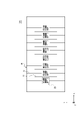
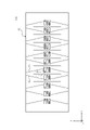
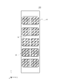
- FIG. 1 is a plan view showing a state of form A of a thermoelectric conversion module (an element body having a plurality of element bodies) according to the first embodiment of the present disclosure
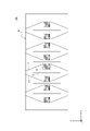
- FIG. 1 is a plan view showing a state of form A of a thermoelectric conversion module (an element body having a single element body) according to the first embodiment of the present disclosure
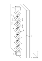
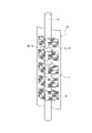
- FIG. 1 is a perspective view showing a state of form B of a thermoelectric conversion module (an element body having a plurality of element bodies) according to the first embodiment of the present disclosure
- FIG. 1 is a perspective view showing a state of form B of a thermoelectric conversion module (an element body having a single element body) according to the first embodiment of the present disclosure
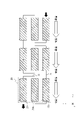
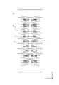
- FIG. 1 is a diagram showing a configuration (uni-leg type) of an element body in a thermoelectric conversion module (an element body having a plurality of element bodies) according to the first embodiment of the present disclosure
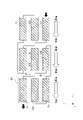
- FIG. FIG. 4 is a diagram showing a modification of the configuration of the element body in the thermoelectric conversion module (the element body having a plurality of element bodies) according to the first embodiment of the present disclosure
- FIG. 4 is a diagram showing a modification of the configuration ( ⁇ type) of the element body in the thermoelectric conversion module (the element body having a plurality of element bodies) according to the first embodiment of the present disclosure
- FIG. 4 is a diagram showing a modification of the configuration (uni-leg type) of the element body in the thermoelectric conversion module (the element body having a single element body) according to the first embodiment of the present disclosure
- FIG. 4 is a diagram showing a modification of the configuration ( ⁇ type) of the element body in the thermoelectric conversion module (the element body having a single element body) according to the first embodiment of the present disclosure
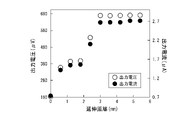
- FIG. 5 is a diagram showing the relationship between the extension distance, the output voltage, and the output current when the thermoelectric conversion module is extended in the longitudinal direction.
- FIG. 5 is a diagram showing the relationship between the extension distance and the output power when the thermoelectric conversion module is extended in the longitudinal direction.
- FIG. 4 is a diagram showing the relationship between the stretching distance and the tensile stress when the thermoelectric conversion module is stretched in the longitudinal direction;
- FIG. 4 is a diagram showing the relationship between the stretching distance and the Seebeck coefficient when the thermoelectric conversion module is stretched in the longitudinal direction.
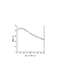
- FIG. 3 is a diagram showing the relationship between the longitudinal length of an element body and the temperature difference occurring in the longitudinal direction of the element body;
- FIG. 4 is a diagram showing the relationship between the longitudinal length of an element body and the generated electromotive force;
- FIG. 4 is a plan view showing a state of form A of a first modified example of the thermoelectric conversion module according to the first embodiment of the present disclosure;
- FIG. 11 is a perspective view showing a state of form B of the first modified example of the thermoelectric conversion module according to the first embodiment of the present disclosure
- FIG. 4 is a plan view showing a state of form A of a second modification of the thermoelectric conversion module according to the first embodiment of the present disclosure
- FIG. 11 is a perspective view showing a state of form B of a second modification of the thermoelectric conversion module according to the first embodiment of the present disclosure
- FIG. 11 is a plan view showing a state of form A of a third modified example of the thermoelectric conversion module according to the first embodiment of the present disclosure
- FIG. 11 is a plan view showing a state of form A of a fourth modified example of the thermoelectric conversion module according to the first embodiment of the present disclosure
- FIG. 11 is a plan view showing a state of form A of a fifth modified example of the thermoelectric conversion module according to the first embodiment of the present disclosure
- FIG. 11 is a perspective view showing a state of form B of a fifth modification of the thermoelectric conversion module according to the first embodiment of the present disclosure
- FIG. 11 is a plan view showing a state of form A of a sixth modification of the thermoelectric conversion module according to the first embodiment of the present disclosure
- FIG. 11 is a plan view showing a state of form A of a seventh modification of the thermoelectric conversion module according to the first embodiment of the present disclosure
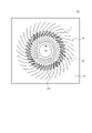
- FIG. 10 is a plan view showing a state of form A of the thermoelectric conversion module according to the second embodiment of the present disclosure
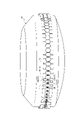
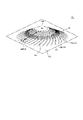
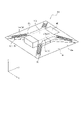
- FIG. 11 is a perspective view showing a state of form B of the thermoelectric conversion module according to the second embodiment of the present disclosure
- FIG. 10 is a plan view showing a state of form A of the thermoelectric conversion module according to the third embodiment of the present disclosure
- FIG. 11 is a perspective view showing a state of form B of the thermoelectric conversion module according to the third embodiment of the present disclosure
- FIG. 10 is a plan view showing a state of form A of the first modified example of the thermoelectric conversion module according to the third embodiment of the present disclosure
- FIG. 11 is a perspective view showing a state of form B of the first modified example of the thermoelectric conversion module according to the third embodiment of the present disclosure
- thermoelectric conversion module 100 includes a base material 10 formed in a sheet shape, and an element body 20 formed on the base material 10 and generating power based on a temperature difference within the thermoelectric conversion module 100 .
- the horizontal direction in FIG. 1A is the X-axis direction
- the vertical direction in FIG. 1A is the Y-axis direction
- the direction perpendicular to the paper surface in FIG. 1A is the Z-axis direction
- the positive side of the Z-axis direction is the front side of the thermoelectric conversion module 100
- the negative side of the Z-axis direction is the rear side of the thermoelectric conversion module 100.
- the base material 10 has a rectangular shape whose longitudinal direction is the X-axis direction in plan view shown in FIG. 1A.
- a plurality of element bodies 20 that perform thermoelectric conversion are arranged at equal intervals in the longitudinal direction (X-axis direction) of the base material 10 .
- the element body 20 includes a plurality of elongated element bodies 21-23, which are p-type thermoelectric conversion elements. can be configured to be electrically connected in series by
- the element body 20 has three element bodies 21-23 arranged in the Y-axis direction.
- the element bodies 21-23 can be composed of carbon nanotubes (CNT), which are p-type thermoelectric conversion elements, for example.
- CNT carbon nanotubes
- the element body 20 may be configured to have a single element body 21 as shown in FIGS. 1B and 3D.
- the element body 20 in the substrate 10, in the region between the plurality of element bodies 20 arranged in the X-axis direction, the element body 20 extends in the Y-axis direction and is arranged at a substantially central position in the Y-axis direction on the substrate 10. and second cuts 13 extending from both sides of the element body 20 in the Y-axis direction to both ends of the substrate 10 in the Y-axis direction.
- the first cut portions 11 and the second cut portions 13 are cut portions penetrating the base material 10 in the thickness direction, and are alternately provided at approximately equal intervals in the longitudinal direction (X-axis direction) of the base material 10 .
- the first cut portion 11 extends beyond the element body 20 in the lateral direction (Y-axis direction) of the base material 10, and is arranged at a substantially central position in the lateral direction (Y-axis direction) of the base material 10. there is In the example of FIG. 1A, the first cut portion 11 has a length of half or more of the length of the base material 10 in the width direction, and both ends of the first cut portion 11 extend in the width direction of the base material 10. It terminates on the inner side of both ends.
- the element main body 20 is arranged at a substantially central position in the lateral direction (Y-axis direction) of the base material 10.
- the second notch 13 extends to both ends.
- the first notches 11 and the second notches 13 extend parallel to each other in the Y-axis direction and are alternately arranged at approximately equal intervals in the X-axis direction.
- thermoelectric conversion module 100 shown in FIG. 1A shows an initial sheet-like state. This sheet-like form will be referred to as "form A" in the specification and claims of the present application.
- form A This sheet-like form will be referred to as "form A" in the specification and claims of the present application.
- the thermoelectric conversion module 100 of form A is stretched in the left-right direction of FIG. 1A and both ends in the longitudinal direction of the thermoelectric conversion module 100 are mounted on the mounting portion 40 that is the stretching means, the first thermoelectric conversion module 100 as shown in FIG.
- the edges 11a and 11b facing each other in the cut portion 11 and the edges 13a and 13b facing each other in the second cut portion 13 are spaced apart in the horizontal direction of FIGS. 1A and 2A, which is the predetermined extending direction.
- thermoelectric conversion module 100 is stretched in the left-right direction of FIG. 1A, which is a predetermined direction, from the state of form A, thereby protruding in the thickness direction of the sheet and forming a three-dimensional structure as shown in FIG. 2A. .
- this conformational form will be referred to as "Form B”.
- the form B is identified by changing the code like "thermoelectric conversion module 101".
- thermoelectric conversion module 101 in the state of form B is placed above the heat source 30 as shown in FIG. 2A.
- the peripheral region of the right end in the longitudinal direction of the plurality of element bodies 21 to 23 (see FIG. 3A) constituting the element body 20 becomes a heat absorbing portion arranged close to the heat source 30 .
- the longitudinal left end regions of the plurality of element bodies 21 to 23 located on the side opposite to the heat source 30 function as heat radiating portions cooled by natural convection of air.
- FIG. 2A shows the configuration of form B in which the element body 20 has a single element body as shown in FIG. 1B.
- FIG. 3A shows an example (so-called "uni-leg type") in which the element body 20 is configured by a plurality of elongated element bodies 21 to 23 that are p-type thermoelectric conversion elements.
- the area labeled 20 in FIG. 1A corresponds to the area labeled 20 in FIG. 3A.
- White arrows in the figure indicate the heat flux from the high temperature side to the low temperature side of the element bodies 21-23, and black arrows indicate the direction of the current flowing through the element bodies 21-23.
- the p-type thermoelectric conversion element when a temperature difference occurs in the element bodies 21-23, holes move from the high temperature side to the low temperature side, so that the low temperature side generates a positive thermoelectromotive force. Therefore, as shown in FIG.
- the high-temperature-side ends of the plurality of element bodies 21-23 are connected in series with the low-temperature-side ends of the adjacent element bodies 21-23 by the wiring 25, and the low-temperature-side ends are connected in series. are connected in series with the ends of the adjacent element bodies 21-23 on the high temperature side by the wiring 25, the element body 20 can obtain a large thermoelectromotive force corresponding to the number of connections of the element bodies 21-23.
- the element body 20 has a single element body as shown in FIG. 1B, for example, as shown in FIG. A body 20 may be configured.
- the high temperature side end of the element body 21 and the low temperature side end of the adjacent element body 21 are connected in series by the wiring 25
- the low temperature side end of the element body 21 is connected to the high temperature side of the adjacent element body 21 . It is configured by connecting in series with the end on the side and the wiring 25 .
- thermoelectric conversion elements for the element bodies 21-23, but n-type thermoelectric conversion elements may be used instead.
- FIG. 3B shows a modification in which the element body 20 is composed of a plurality of elongated element bodies 21, 22A, and 23 including p-type thermoelectric conversion elements and n-type thermoelectric conversion elements.
- the area labeled 20 in FIG. 1A corresponds to the area labeled 20 in FIG. 3B.
- the p-type thermoelectric conversion element when there is a temperature difference between the element bodies 21 and 23 as described above, holes move from the high temperature side to the low temperature side, so that the low temperature side generates thermoelectromotive force with the positive electrode.
- thermoelectric conversion element when a temperature difference occurs in the element body 22A, electrons move from the high temperature side to the low temperature side, so that the high temperature side generates thermoelectromotive force with the positive electrode. Therefore, as shown in FIG. 3B, the high-temperature-side ends of the element bodies 21 and 23, which are p-type thermoelectric conversion elements, are connected to the high-temperature-side ends of the adjacent n-type thermoelectric conversion element 22A or the adjacent p-type thermoelectric conversion elements.
- the low-temperature side ends of the element bodies 21 and 23, which are p-type thermoelectric conversion elements, are connected in series to the low-temperature side ends of the element bodies 21 and 23, which are p-type thermoelectric conversion elements, and the adjacent n-type thermoelectric elements are connected to the low-temperature side ends of the element bodies 21 and 23, which are p-type thermoelectric conversion elements.
- the element body 20 By connecting the low-temperature side end of the element body 22A that is a conversion element or the high-temperature side ends of the adjacent element bodies 21 and 23 that are p-type thermoelectric conversion elements in series with the wiring 25, the element body 20 can A large thermoelectromotive force corresponding to the number of connections of the bodies 21, 22A, 23 can be obtained.
- FIG. 3C shows a modification ( The so-called " ⁇ -type") is shown.
- the area labeled 20 in FIG. 1A corresponds to the area labeled 20 in FIG. 3C.
- the p-type thermoelectric conversion element when a temperature difference occurs in the element bodies 21, 22, and 23 as described above, holes move from the high temperature side to the low temperature side, so that the low temperature side generates thermoelectromotive force with the positive electrode.
- the n-type thermoelectric conversion element when a temperature difference occurs in the element bodies 21A, 22A, and 23A, electrons move from the high temperature side to the low temperature side, so that the high temperature side generates thermoelectromotive force with the positive electrode. Therefore, as shown in FIG.
- the high-temperature side ends of the element bodies 21, 22, and 23, which are p-type thermoelectric conversion elements are connected to the high-temperature side ends of the adjacent n-type thermoelectric conversion element bodies 21A, 22A, and 23A.
- the ends of the element bodies 21, 22, and 23, which are p-type thermoelectric conversion elements, are connected in series with the wiring 25, and the ends of the element bodies 21, 22, and 23, which are p-type thermoelectric conversion elements, on the low temperature side are connected to the adjacent element bodies 21A, 22A, and 23A which are n-type thermoelectric conversion elements.
- the element body 20 can be configured by an elongated element body 21A that is an element.
- the high temperature side end of the element body 21 is connected in series with the high temperature side end of the adjacent element body 21A by the wiring 25, and the low temperature side end of the element body 21 is connected to the low temperature side of the adjacent element body 21A. It is configured by connecting in series with the end on the side and the wiring 25 .
- thermoelectric conversion material for forming the p-type thermoelectric conversion elements and the n-type thermoelectric conversion elements constituting the element bodies 21 to 23 is not particularly limited, and bismuth tellurium is used. based compounds, antimony-based compounds, silicon-based compounds, metal oxide-based compounds, Heusler alloy-based compounds, conductive polymer compounds, conductive fibers, composite materials thereof, and the like. Among them, conductive fibers are preferably used, and fibrous carbon nanostructures such as carbon nanotubes (hereinafter also referred to as CNTs) are more preferably used. If CNTs are used, the mechanical strength of the thermoelectric conversion module 100 of the present disclosure can be further improved and the weight can be reduced.
- CNTs fibrous carbon nanostructures
- CNTs are not particularly limited, and single-walled CNTs and/or multi-walled CNTs can be used, but the CNTs are preferably single-walled CNTs. This is because single-walled CNTs tend to have superior thermoelectric properties (Seebeck coefficient).
- single-walled carbon nanotubes when synthesizing CNTs by a chemical vapor deposition method (CVD method) by supplying a raw material compound and a carrier gas onto a base material having a catalyst layer for CNT production on the surface,
- CVD method chemical vapor deposition method
- a method of dramatically improving the catalytic activity of the catalyst layer by allowing a trace amount of oxidizing agent (catalyst activating substance) to exist in the system (super-growth method; see International Publication No. 2006/011655).
- oxidizing agent catalyst activating substance
- SGCNT Manufactured CNTs can be used (hereinafter, CNTs manufactured according to such a method may be referred to as "SGCNT").
- SGCNT has the characteristic that there are many bends.
- CNTs have high thermal conductivity due to electron transfer, they are also considered to have a high effect of lowering thermal conductivity due to phonon vibration.
- SGCNTs have more bends than CNTs produced according to other general methods, they have a structure in which phonon vibrations are less likely to be amplified, and a decrease in thermal conductivity due to phonon vibrations can be suppressed. . Therefore, SGCNT can be a superior material as a thermoelectric conversion material compared to other general CNTs.
- FIG. 4A shows the output voltage of the thermoelectric conversion element when the thermoelectric conversion module (however, in FIG. 1A, the entire shape of the base material 10 is composed of thermoelectric conversion elements) is stretched in a state of being close to the heat source.
- 4B shows the output current
- FIG. 4B shows the output power of the thermoelectric conversion element when the thermoelectric conversion module is extended.
- thermoelectric conversion module by extending the thermoelectric conversion module in the longitudinal direction, the angle between the longitudinal direction of the thermoelectric conversion element and the surface of the heat source increases, so the temperature difference within the thermoelectric conversion element increases. It is thought that the thermoelectromotive force in the thermoelectric conversion element increases as a result.
- thermoelectric conversion module by stretching the thermoelectric conversion module in the longitudinal direction, as shown in FIG. 4C, the tensile stress applied to the thermoelectric conversion module increases, and accordingly, as shown in FIG. This is considered to be because the heat energy itself increases and the thermoelectric conversion efficiency increases.
- thermoelectric conversion module the increase in the Seebeck coefficient itself due to the stretching of the thermoelectric conversion module is caused by the change in the electronic structure when a single CNT undergoes a structural change such as bending. That is, it is thought that the bending of the CNTs changes the electrical properties and increases the Seebeck coefficient.
- thermoelectric conversion element When the Seebeck coefficient itself is increased by stretching the thermoelectric conversion module in the longitudinal direction, only CNT may be used as the material of the thermoelectric conversion element.
- a material obtained by blending (VDF-TrFE) with CNT may also be used.
- the CNT When the CNT is mixed with another material to increase the Seebeck coefficient by stretching, the other material is not limited to those mentioned above, and may be any material that enhances the change in the electronic state of the CNT. It is preferably a ferroelectric material with polarization.
- the longitudinal length of the elongated element bodies 21-23 is preferably 30 [mm] or more, more preferably 40 [mm] or more, and most preferably 60 [mm] or more. preferable.
- the element body contains CNT, the thickness of the element body: 80 [ ⁇ m], the thermal conductivity in the plane direction of the element body: 10 [W / (m K)], the thermal conductivity in the thickness direction of the element body: Assuming the conditions of 0.1 [W/(mK)] and the temperature difference between the heat source temperature and the ambient temperature: 100 [K], the temperature difference in the element body erected on the surface of the heat source is as shown in FIG. The simulation results were as shown in .
- the length of the element body is at least 30 [mm] or longer, it becomes easier to ensure the temperature difference in the element body.
- the thickness of the base material which has thermal conductivity smaller than that of CNT by two orders of magnitude or more, does not significantly affect the temperature difference of the element body. I found out.
- the width of the element body is d
- the length in the longitudinal direction is L: L1
- the number of element bodies is n1
- the longer the length L in the longitudinal direction the larger the temperature difference between the longitudinal ends can be taken, so the electromotive force of one element body increases, but the number of element bodies n decreases. .
- the final electromotive force obtained in the thermoelectric conversion module is the electromotive force of one element multiplied by the number n of element bodies
- the length L of the element bodies in the longitudinal direction can be increased.
- the temperature difference of one element body is increased by increasing the temperature difference of one element body, and when the longitudinal length L of the element body is shortened and the number n of element bodies is increased, the final electromotive force obtained changes, and the maximum It is believed that there is an optimal value for the longitudinal length L of the element assembly that provides a large electromotive force.
- FIG. 5B shows the result of examining this by simulation, and it was found that the largest electromotive force was obtained when the length L of the element body in the longitudinal direction was 6 mm.
- the longitudinal length L of the element body is 5 mm or less, the electromotive force is significantly reduced, whereas when the longitudinal length L of the element body is increased, the electromotive force is gently reduced.
- the longitudinal length L of the element body is preferably 5 mm or more and 12 mm or less, more preferably 5 mm or more and 8 mm or less.
- thermoelectric conversion module according to the first embodiment of the present disclosure will be described with reference to FIGS. 6 and 7.
- FIG. 6 first modified example of the thermoelectric conversion module according to the first embodiment of the present disclosure will be described with reference to FIGS. 6 and 7.
- thermoelectric conversion module 110 according to a first modification of the first embodiment, as shown in FIG. and an element body 20 for generating power.
- the base material 10 is a sheet-like member having an annular shape in plan view shown in FIG.
- the base 10 has a first element body 20 extending radially in a region between the plurality of element bodies 20 arranged in the circumferential direction and arranged at a substantially central position in the radial direction of the base 10 . It has cuts 11 and second cuts 13 extending from both radial sides of the element body 20 to both radial ends of the substrate 10 .
- the first cut portions 11 and the second cut portions 13 are cut portions penetrating the base material 10 in the thickness direction, and are provided alternately in the circumferential direction of the base material 10 .
- the first cut portion 11 extends beyond the element body 20 in the radial direction of the base material 10 and is arranged at a substantially central position in the radial direction of the base material 10 .
- the first cut portion 11 has a length of at least half the radial length of the substrate 10 , and both ends of the first cut portion 11 terminate inside the both radial ends of the substrate 10 . ing.
- the element body 20 is arranged at a substantially central position in the radial direction of the base material 10, and the second incision is made from both sides of the element body 20 in the radial direction to both ends of the base material 10 in the radial direction.
- a portion 13 extends.
- the first cuts 11 and the second cuts 13 both extend in the radial direction and are alternately arranged at substantially equal intervals in the circumferential direction.
- thermoelectric conversion module 110 shown in FIG. 6 is in a sheet-like initial state (form A).
- the thermoelectric conversion module 110 of form A is deformed so that the radial direction thereof is oriented in the vertical direction, and is attached to the outer peripheral surface of the substantially cylindrical heat source 41 shown in FIG.
- the edges 11a and 11b facing each other in 11 and the edges 13a and 13b facing each other in the second notch 13 are separated in the circumferential direction of the cylindrical heat source 41, which is the predetermined extending direction.
- one of the edges 11b and 13b of the first cut portion 11 and the second cut portion 13 is flexurally deformed radially outward of the heat source 41, and the other edge 11a and 13a is flexed radially inward of the heat source 41. transform. Due to the bending deformation of the edge portions of the first cut portion 11 and the second cut portion 13, in the example of FIG. 7, the left end portion of the element body 20 protrudes radially outward of the heat source 41 in the thickness direction of the sheet. Further, the right end portion of the element body 20 protrudes radially inward of the heat source 41 in the thickness direction of the sheet (see FIG. 7).
- thermoelectric conversion module 110 extends in the circumferential direction of the heat source 41, which is a predetermined direction, from the state of form A, thereby protruding in the thickness direction of the sheet and forming a three-dimensional structure as shown in FIG. B).
- Form B is identified by changing the sign from form A, such as "thermoelectric conversion module 111".
- thermoelectric conversion module 111 in the state of form B is arranged on the outer peripheral surface of the heat source 41 as shown in FIG.
- the left end region in the longitudinal direction located on the side opposite to the heat source 41 in the plurality of element bodies functions as a heat radiating section cooled by natural convection of air.
- third cuts 11A are provided at four locations in the circumferential direction.
- the third cut portion 11A is used as a boundary when the annular shape A in FIG. 6 is transformed into the shape B shown in FIG.
- One side can be reversed and the inner circumference side and the outer circumference side can be exchanged.
- the modification shown in FIG. 6 has a shape in which the thermoelectric conversion module 100 extending in the horizontal direction in FIG. 1A is extended in the circumferential direction. Therefore, for the configuration of the element body 20, for example, configurations shown in FIGS. 3A to 3E can be adopted.
- thermoelectric conversion module [Second Modification of First Embodiment] Next, a second modification of the thermoelectric conversion module according to the first embodiment of the present disclosure will be described with reference to FIGS. 8 and 9.
- FIG. 8
- thermoelectric conversion module 120 includes a sheet-like base material 10 formed in a rectangular shape and a and an element body 20 for generating power.
- the base material 10 is a sheet-like member having a rectangular shape in plan view shown in FIG. As shown in FIG. 8, on the substrate 10, a total of four element bodies (FIG. 8 ) is defined as one unit (element body 20), and a plurality of these are arranged in the longitudinal direction of the substrate 10. As shown in FIG. In the region between the plurality of element bodies 20 in the X-axis direction, the first cut portions 12 arranged at substantially the center position in the Y-axis direction of the base material 10 and crossing each other, and the base material from both sides of the element body 20 in the Y-axis direction. and second cut portions 13 extending to both ends of the material 10 in the Y-axis direction. The first cut portion 12 and the second cut portion 13 are cut portions penetrating through the base material 10 in the thickness direction.
- thermoelectric conversion module 120 shown in FIG. 8 is in a sheet-like initial state "form A". With the thermoelectric conversion module 120 of form A stretched in the left-right direction (X-axis direction) in FIG. The edge portions 12a and 12b facing each other in the portion 12 and the edge portions 13a and 13b facing each other in the second cut portion 13 are separated from each other in the lateral direction of FIGS. 8 and 9, which is the predetermined extending direction. As a result, the spear point-like portion surrounded by the first cut portion 12 and the second cut portion 13 connecting the element bodies 20 in FIG. 8 extends in the X-axis direction.
- thermoelectric conversion module 121 of form B shown in FIG. 9 When the thermoelectric conversion module 121 of form B shown in FIG. 9 is placed on a heat source (not shown), the above-mentioned spearhead-shaped portion extending in the X-axis direction functions as a heat absorbing portion by being close to the heat source, and the element in FIG.
- the temperature of both ends of the main body 20 in the Y-axis direction is increased.
- both ends of the element body 20 in the Y-axis direction are on the high temperature side, and the central portion of the element body 20 on the Y-axis direction is on the low temperature side, and a temperature difference occurs in the longitudinal direction of the element body.
- the high-temperature-side ends of the element bodies which are a plurality of p-type thermoelectric conversion elements, are connected in series to the low-temperature-side ends of the adjacent element bodies by wiring, and the low-temperature-side is connected in series with the high-temperature side end of the adjacent element body by wiring, the element body 20 can obtain a large thermoelectromotive force corresponding to the number of connected element bodies.
- the high temperature side end of the element body that is the p-type thermoelectric conversion element is the high temperature side end of the element body that is the adjacent n-type thermoelectric conversion element or the adjacent p
- the element body, which is an n-type thermoelectric conversion element is connected in series with the low-temperature side end of the element body, which is a p-type thermoelectric conversion element, by wiring, and is adjacent to the low-temperature side end of the element body, which is a p-type thermoelectric conversion element.
- the element body 20 By connecting the end on the low temperature side or the end on the high temperature side of the element body which is the adjacent p-type thermoelectric conversion element in series by wiring, the element body 20 generates a large thermoelectromotive force corresponding to the number of connected element bodies. Obtainable.
- the high temperature side end of the element body that is the p-type thermoelectric conversion element is connected in series with the high temperature side end of the adjacent n-type thermoelectric conversion element by wiring.
- the element body 20 is connected in series with the low temperature side end of the element body that is the p-type thermoelectric conversion element and the adjacent n-type thermoelectric conversion element that is the low temperature side end of the element body by wiring. , a large thermoelectromotive force corresponding to the number of connections of the element bodies can be obtained.
- thermoelectric conversion module [Third Modification and Fourth Modification of First Embodiment] Next, a third modified example and a fourth modified example of the thermoelectric conversion module according to the first embodiment of the present disclosure will be described with reference to FIGS. 10 and 11.
- FIG. 10 shows a third modified example and a fourth modified example of the thermoelectric conversion module according to the first embodiment of the present disclosure.
- thermoelectric conversion module 130 according to a third modified example and a thermoelectric conversion module 140 according to a fourth modified example of the first embodiment are, as shown in FIGS. and an element body 20 which is formed on the substrate 10 and generates power based on the temperature difference.
- thermoelectric conversion module 130 in the thermoelectric conversion module 130 according to the third modification, the second cut portions 13 provided at line-symmetrical positions with respect to the first cut portions 11 oriented in the Y-axis direction are different from the first embodiment. It is similar to the first embodiment except that it extends at an angle to the axial direction.
- a fourth modification shown in FIG. 11 also has a configuration similar to that of the third modification, except that the pitch of the cut portions in the X-axis direction is different from that of the third modification. Therefore, detailed description here is omitted.
- thermoelectric conversion module [Fifth Modification of First Embodiment] Next, a fifth modification of the thermoelectric conversion module according to the first embodiment of the present disclosure will be described with reference to FIGS. 12 and 13.
- FIG. 12 a fifth modification of the thermoelectric conversion module according to the first embodiment of the present disclosure will be described with reference to FIGS. 12 and 13.
- FIG. 12 a fifth modification of the thermoelectric conversion module according to the first embodiment of the present disclosure will be described with reference to FIGS. 12 and 13.
- thermoelectric conversion module 150 includes a sheet-like base material 10 formed in a rectangular shape and a and an element body 20 for generating power.
- the base material 10 is a sheet-like member having a rectangular shape in plan view shown in FIG.
- the substrate 10 is provided with an element body 20 in which three element bodies are arranged in a direction toward the positive side in the X-axis direction and the brass side in the Y-axis direction.
- the element bodies 20 are arranged side by side at substantially equal intervals in the X-axis direction.
- a first notch 14 extending in the arrangement direction of the element bodies is provided outside the longitudinal end of each element body in the element body 20 .
- the first cut portion 14 is arranged at a substantially central position in the Y-axis direction of the base material 10 and is inclined with respect to the Y-axis direction, and terminates in a region inside both ends of the base material 10 in the Y-axis direction. is doing.
- the base material 10 has second cuts 13 extending to both ends of the base material 10 in the Y-axis direction except for the region of the element body 20 .
- the first cut portion 12 and the second cut portion 13 are cut portions penetrating through the base material 10 in the thickness direction.
- the thermoelectric conversion module 150 shown in FIG. 12 is in a sheet-like initial state (form A).
- the thermoelectric conversion module 150 of form A is stretched in the left-right direction of FIG. 12 and both ends in the longitudinal direction of the thermoelectric conversion module 150 are mounted on mounting portions (not shown) that are extension means, a second
- the edges 14a and 14b facing each other in the first notch 14 and the edges 13a and 13b facing each other in the second notch 13 are separated from each other in the horizontal direction of FIGS. 12 and 13, which is the predetermined extending direction.
- the edges 14a and 13a on the left side in FIG. 13 are flexurally deformed upward
- the edge portions 14b and 13b on the right side in FIG. 13 are flexurally deformed downward. Due to the bending deformation of the edges of the first cut portion 14 and the second cut portion 13, in the example of FIG. Further, the left end portion of the element body 20 protrudes downward (back side) in the thickness direction of the sheet (see FIG. 13).
- thermoelectric conversion module 150 is stretched in the left-right direction of FIG. 12, which is a predetermined direction, from the state of form A, so that it protrudes in the thickness direction of the sheet and has a three-dimensional structure as shown in FIG. B).
- the longitudinal right end portion of each element body constituting the element body 20 protrudes upward, and the longitudinal left end portion of each element body protrudes downward. Therefore, by arranging the thermoelectric conversion module 150 shown in FIG. 13 on a heat source, it is possible to create a temperature difference in the longitudinal direction of each element body constituting the element body 20 . Therefore, thermoelectric conversion characteristics can be enhanced.
- thermoelectric conversion module 160 according to a sixth modification of the first embodiment and a thermoelectric conversion module 170 according to a seventh modification are, as shown in FIGS. and an element main body 20 which is formed in the body and generates power based on the temperature difference.
- thermoelectric conversion module 160 compared to the first embodiment, the plurality of first cuts 11 oriented in the Y-axis direction and arranged at equal intervals in the X-axis direction are arranged in the X-axis direction. It is similar to the first embodiment, except that it is gradually offset in the negative direction along the Y axis toward the positive side.
- the outer shape of the base material 10 is a rhombus, and the element main body 20 and the notch are not provided in the central portion in the X-axis direction. Others are similar to the configuration of the first embodiment. Therefore, detailed description here is omitted.
- the present embodiment is a sheet-shaped thermoelectric conversion module that is placed in contact with or in close proximity to a heat source and generates power based on the temperature difference between a portion near the heat source and a portion away from the heat source.
- the thermoelectric conversion module 100 has a cut portion penetrating in the thickness direction of the sheet, and the thermoelectric conversion module 100 is stretched in a predetermined direction so that the edges of the cut portion facing each other are separated from each other from the sheet-like form A. It was constructed so as to deform into a three-dimensional structure form B projecting in the sheet thickness direction.
- the sheet-shaped thermoelectric conversion module 100 is deformed into a three-dimensional structure by a simple method of stretching in a predetermined direction and brought close to the heat source, thereby increasing the temperature inside the sheet-shaped thermoelectric conversion module 100.
- the thermoelectric conversion characteristics can be improved.
- the sheet-like base material 10 and the element body 20 formed on the base material 10 are provided.
- the portions protruding in the thickness direction of the sheet in the thermoelectric conversion module 100 can be formed with thermoelectric conversion elements, so that the thermoelectric conversion characteristics can be improved using a smaller amount of thermoelectric conversion material. be able to.
- the element body 20 includes element bodies 21 to 23 formed in an elongated shape, and the element bodies 21 to 23 have both ends in the longitudinal direction of the element body in the state of the form B. It is preferable that they are arranged so as to be separated from each other in the projecting direction. By adopting such a configuration, it is possible to efficiently obtain a temperature difference in the longitudinal direction of the element body by bringing the back surface of the sheet close to the heat source, thereby improving thermoelectric conversion characteristics.
- the element body 20 includes a plurality of element bodies 21 to 23 formed in an elongated shape, and the plurality of element bodies 21 to 23 have adjacent element bodies at the ends in the longitudinal direction. Electrically connected in series is preferred. By adopting such a configuration, the thermoelectromotive force generated in the element body can be increased by the series connection and output.
- the element bodies 21 to 23 are configured to contain carbon nanotubes.
- the length in the longitudinal direction of the element bodies 21-23 is configured to be 30 mm or more.
- the length in the longitudinal direction of the element bodies 21-23 is configured to be 5 mm or more and 12 mm or less.
- the thermal conductivity of the base material is configured to be 5.0 [W/(m ⁇ K)] or less.
- thermoelectric conversion module 100 in the state of form B corresponds to the element main body 20 as the power generation section, the heat absorption section in contact with or in close proximity to the heat source 30, and the radiator having a temperature lower than that of the heat source 30.
- a heat radiating section may be provided that is in contact with or in close proximity to the heat absorbing section and that is disposed on the opposite side of the heat absorbing section in the direction in which the sheet protrudes.
- thermoelectric conversion characteristics can be improved.
- the predetermined direction is configured to be a direction substantially perpendicular to the extending direction of the notch in the in-plane direction of the thermoelectric conversion module 100 in the state A.
- the thermoelectric conversion module 100 can be stretched in a predetermined direction to increase the bending around the cut portion and protrude in the thickness direction of the sheet, thereby effectively creating a temperature difference within the element body 20 . can be done.
- the cut portions include the first cut portion 11 arranged at a substantially central position in the direction perpendicular to the predetermined direction in the region between the plurality of element bodies 20 arranged in the predetermined direction, and the element bodies 20 second cuts 13 extending to both ends of the thermoelectric conversion module 100 from both sides in a direction orthogonal to a predetermined direction in did.
- the edge portions 11a and 11b of the first cut portion 11 are separated to facilitate displacement of the end portion of the element body 20 in a predetermined direction in the direction orthogonal to the sheet thickness, and the second cut portion 13 can be easily displaced.
- the edges 13a and 13b the rigidity in the direction in which the element body 20 stands up can be further reduced.
- thermoelectric conversion module 200 includes a sheet-like substrate 10 and an element body 20 formed on the substrate 10 and generating power based on the temperature difference within the thermoelectric conversion module 200. ing.
- the base material 10 has a substantially square shape in plan view shown in FIG.
- the base material 10 has a cut portion 15 spirally extending from an annular inner peripheral portion 10b having an opening 10a toward an outer peripheral portion 10c provided concentrically with the inner peripheral portion 10b.
- a plurality of cut portions 15 are formed at approximately equal intervals in the circumferential direction.
- an element body 20 for thermoelectric conversion is arranged in a region between the notches 15 adjacent in the circumferential direction.
- thermoelectric conversion module 200 shown in FIG. 16 is in a sheet-like initial state (form A).
- the inner peripheral portion 10b of the thermoelectric conversion module 200 of Mode A is stretched in the thickness direction of the sheet in FIG.
- the edge portions 15a and 15b of the cut portion 15 facing each other are separated from each other in the substantially horizontal direction.
- the end portion on the inner peripheral side of the element main body 20 is displaced upward (front side) in the thickness direction of the sheet (see FIG. 17).
- thermoelectric conversion module 200 is stretched in a predetermined direction perpendicular to the paper surface of FIG. 16 from the state of form A, thereby protruding in the thickness direction of the sheet and having a three-dimensional structure as shown in FIG. (Form B). Moreover, the form B is identified by changing the code like "thermoelectric conversion module 201".
- thermoelectric conversion module 201 in form B can be placed on a heat source (not shown).
- a heat source not shown
- the outer peripheral side in the longitudinal direction of the element body that constitutes the element body 20 becomes a heat absorbing portion arranged close to the heat source 30 .
- the longitudinally inner peripheral side of the element body located on the side opposite to the heat source functions as a heat radiating section cooled by natural convection of air.
- thermoelectric conversion element When a p-type thermoelectric conversion element is used for the element body constituting the element main body 20, similarly to the configuration of FIG.
- the low-temperature side end (the radially inner end in the example of FIG. 17) of one element body adjacent in the direction is connected in series by wiring, and the low-temperature side end is connected in the circumferential direction to the other element body adjacent in the circumferential direction.
- the element body 20 can obtain a large thermoelectromotive force corresponding to the number of connected element bodies by connecting in series with the end on the high temperature side by wiring.
- an element body which is one p-type thermoelectric conversion element, is arranged on the upper surface (surface) of each spiral arm 15c partitioned by the notch 15, but it is not limited to this aspect.
- n-type thermoelectric conversion elements may be arranged.
- the entire spiral arm 15c may be formed of a thermoelectric conversion element.
- one p-type thermoelectric conversion element and one n-type thermoelectric conversion element are arranged on each of the front and back sides of each spiral arm 15c, and the end of the element body, which is the p-type thermoelectric conversion element, on the high temperature side is on the opposite side of the spiral arm 15c.
- thermoelectric conversion element It is an n-type thermoelectric conversion element that is connected in series with the high temperature side end of the element body that is the n-type thermoelectric conversion element of the surface by wiring, and that the low temperature side end of the element body that is the p-type thermoelectric conversion element is adjacent. It may be configured so as to be connected in series with the low-temperature side end of the element assembly by wiring.
- the predetermined direction is configured to be substantially perpendicular to the in-plane direction of the sheet-like thermoelectric conversion module 200 of form A.
- the direction in which the stretching means pulls the thermoelectric conversion module 200 coincides with the stretching direction of the thermoelectric conversion module 200, so that the thermoelectric conversion module 200 can be reliably stretched by the stretching amount necessary for desired power generation. can be done.
- the notch 15 spirally extends from the inner peripheral portion 10b of the thermoelectric conversion module 200 in the state of A to the outer peripheral portion 10c provided concentrically with the inner peripheral portion 10b.
- the inner peripheral portion 10b protrudes in the thickness direction of the thermoelectric conversion module 200, and either the inner peripheral portion 10b or the outer peripheral portion 10c is arranged in contact with or close to the heat source.
- the thermoelectric conversion module 200 has an axially symmetrical structure, and each element body can stably generate power corresponding to the protrusion amount of the inner peripheral portion 10b.
- thermoelectric conversion module 300 includes a sheet-like substrate 10 and an element body 20 formed on the substrate 10 and generating power based on the temperature difference within the thermoelectric conversion module 300. ing.
- the base material 10 has a rectangular shape elongated in the Y-axis direction in plan view shown in FIG.
- the substrate 10 is formed with an element body 20 that performs thermoelectric conversion and is composed of a total of six element bodies arranged in two in the X-axis direction and three in the Y-axis direction.
- four element bodies 20 are arranged at predetermined intervals in the Y-axis direction as shown in FIG. 10 are provided with notches 16 that terminate inside of both ends in the X-axis direction. Therefore, two parallel cuts 16 are provided between the element bodies 20 as shown in FIG.
- the notches 16 extend substantially in the same direction (X-axis direction) in the in-plane direction of the thermoelectric conversion module 300 and are spaced apart in the Y-axis direction.
- thermoelectric conversion module 300 shown in FIG. 18 is in a sheet-like initial state (form A).
- a rod-shaped member 43 as an extending means extends from the front surface of the thermoelectric conversion module 300 (the surface where the element body 20 is arranged in FIG. 18) to the rear surface.
- the rod-like members 43 are mounted so as to alternately pierce the cut portions 16 from the rear surface to the front surface.
- the opposing edges 16a and 16b of the cut portion 16 are spaced apart in the thickness direction of the sheet, and the central position of the element body 20 in the X-axis direction is located from the thermoelectric conversion module 300 of form A to the thickness of the sheet.
- thermoelectric conversion module 300 protrudes upward (front side) and transforms into a three-dimensional form (form B).
- the regions where the element bodies 20 are arranged protrude to the front side of the thermoelectric conversion module 300, and the regions between the element bodies 20 in the Y-axis direction are the thermoelectric conversion modules 300. protrude on the back side.
- thermoelectric conversion module 301 in the state of form B can be placed on a heat source (not shown) such that the back surface of the thermoelectric conversion module 301 is close to the heat source.
- the longitudinal outer side of the element body that constitutes the element body 20 becomes a heat absorbing portion that is arranged close to the heat source 30 .
- the longitudinal inner side of the element body located on the side opposite to the heat source functions as a heat radiating section cooled by natural convection of air.
- the high temperature side end of the element body (the outer end in the example of FIG. 19) is adjacent to By connecting the low-temperature side end of the element body (inside end in the example of FIG. 19) in series with the wiring, and connecting the low-temperature side end with the high-temperature side of the adjacent element body in series with the wiring. , the element body 20 can obtain a large thermoelectromotive force corresponding to the number of connections of the element bodies.
- the ends of the p-type thermoelectric conversion elements on the high temperature side are adjacent to each other as in the configuration of FIG. 3B.
- the high temperature side end of the n-type thermoelectric conversion element or the low temperature side end of the adjacent p-type thermoelectric conversion element is connected in series by wiring, and the low temperature side end is connected to the low temperature side of the adjacent n-type thermoelectric conversion element or the high-temperature-side ends of the adjacent p-type thermoelectric conversion elements in series by wiring, the element body 20 can obtain a large thermoelectromotive force corresponding to the number of connected element bodies.
- the high temperature side end of the p-type thermoelectric conversion element is connected in series with the high temperature side end of the adjacent n-type thermoelectric conversion element by wiring, and the low temperature side end is connected to the adjacent n-type thermoelectric conversion element.
- the element body 20 can obtain a large thermoelectromotive force corresponding to the number of connected element bodies by connecting in series with the ends of the n-type thermoelectric conversion elements on the low temperature side by wiring.
- thermoelectric conversion module [First Modification of Third Embodiment] Next, a first modification of the thermoelectric conversion module according to the third embodiment of the present disclosure will be described with reference to FIGS. 20 and 21.
- FIG. 20 First Modification of Third Embodiment
- the thermoelectric conversion module 310 includes a sheet-like substrate 10 and an element body 20 formed on the substrate 10 and generating power based on the temperature difference within the thermoelectric conversion module 310. ing.
- the base material 10 has a substantially square shape in plan view shown in FIG.
- the substrate 10 has a central cut portion 17 for forming a substantially square central portion 17c of the substrate 10, and radially extending from the central portion 17c toward the corners of the substrate 10.
- An arm notch 18 is provided to define the arm 18c.
- the arm portion 18c is partitioned from the outer peripheral portion 10e by the arm cut portion 18.
- an element body 20 extending in the longitudinal direction of the arm portions 18c is arranged.
- thermoelectric conversion module 310 shown in FIG. 20 is in a sheet-like initial state (form A).
- a rectangular parallelepiped corner member 45 as an extending means is attached to the rear surface of the central portion 17c and the outer peripheral portion 10e.
- the opposing edges 17a, 17b of the central cutout 17 are spaced apart in the thickness direction of the sheet, and the opposing edges 18a, 18b of the arm cuts 18 are spaced apart in the thickness direction of the sheet.
- the central portion 17c of the thermoelectric conversion module 310 of form A protrudes upward (front side) in the thickness direction of the sheet, and is deformed into a three-dimensional form (form B).
- thermoelectric conversion module 311 in the state of form B can be placed on a heat source (not shown) such that the back surface of the thermoelectric conversion module 311 is close to the heat source.
- the longitudinal outer side of the element body that constitutes the element body 20 becomes a heat absorbing portion that is arranged close to the heat source 30 .
- the longitudinal inner side of the element body located on the side opposite to the heat source functions as a heat radiating section cooled by natural convection of air.
- the high temperature side end of the element body (the outer end in the example of FIG. 21) is replaced with another By connecting the end of the element body on the low temperature side (the inner end in the example of FIG. 21) in series by wiring, and by connecting the end on the low temperature side to the end on the high temperature side of the other element body in series by wiring. , the element body 20 can obtain a large thermoelectromotive force corresponding to the number of connections of the element bodies.
- the high temperature side end of the p-type thermoelectric conversion element is The high temperature side end of the n-type thermoelectric conversion element or the low temperature side end of the other p-type thermoelectric conversion element is connected in series by wiring, and the low temperature side end is connected to the low temperature side of the other n-type thermoelectric conversion element or the high-temperature-side end of another p-type thermoelectric conversion element in series by wiring, the element body 20 can obtain a large thermoelectromotive force corresponding to the number of connected element bodies.
- the high temperature side end of the p-type thermoelectric conversion element is connected in series with the high temperature side end of another n-type thermoelectric conversion element by wiring,
- the element body 20 can obtain a large thermoelectromotive force corresponding to the number of connected element bodies.
- the plurality of cut portions 16 extending substantially in the same in-plane direction of the thermoelectric conversion module 300 in the state of A are spaced apart in a direction substantially orthogonal to the extending direction of the cut portions.
- the extending means alternately pierces the plurality of cuts 16 from the front surface to the back surface and from the back surface to the front surface of the thermoelectric conversion module 300, so that the area between the adjacent cuts 16 extends to the front side of the thermoelectric conversion module. And it was configured to transform into the state of form B alternately protruding to the back side.
- the rod-shaped member alternately pierces the notches 16 from the front surface to the back surface and from the back surface to the front surface of the thermoelectric conversion module 300, so that a part of the base material 10 is stabilized in the thickness direction of the sheet.
- a temperature difference can be reliably provided in the element body 20 . Therefore, thermoelectric conversion characteristics can be improved.
- the center portion 17 c provided at the substantially center position in the in-plane direction of the thermoelectric conversion module 310 in the state of Mode A and formed by the center cut portion 17 to be partitioned with respect to the outer peripheral portion 10 e is the arm cut portion 18 .
- a part of the substrate 10 stably protrudes in the thickness direction of the sheet, so that a temperature difference can be reliably provided in the element body 20 . Therefore, thermoelectric conversion characteristics can be improved.
- thermoelectric conversion module may be entirely formed of thermoelectric conversion elements without providing the substrate 10 .
- the ends of the thermoelectric conversion module in the extension direction are configured to extend in a predetermined direction by being attached to the attachment portion, but the present invention is not limited to this aspect.
- the thermoelectric conversion module may be stretched in a predetermined direction when the user wears clothing or the like sewn with the thermoelectric conversion module, or the user may stretch the thermoelectric conversion module by pulling it in a predetermined direction.
- the stretching means of the present disclosure includes a broad concept that can stretch the thermoelectric conversion module in a predetermined direction.
- thermoelectric conversion module 100 it is possible to provide a sheet-shaped thermoelectric conversion module 100 with excellent thermoelectric conversion characteristics.
Landscapes
- Engineering & Computer Science (AREA)
- Manufacturing & Machinery (AREA)
- Cooling Or The Like Of Semiconductors Or Solid State Devices (AREA)
- Electromechanical Clocks (AREA)
- Electric Clocks (AREA)
Abstract
Description
前記形態Aの状態の前記熱電変換モジュールの面内方向における略同一方向に延びる複数の前記切込み部が、該切込み部の延在方向に略直交する方向に離間して配置され、
延伸手段が前記複数の前記切込み部を前記熱電変換モジュールの表面から裏面へ及び裏面から表面へと交互に貫くことによって、隣接する前記切込み部の間の領域が前記熱電変換モジュールの表側及び裏側に交互に突出した形態Bの状態へと変形することが好ましい。このような構成の採用によって、棒状部材が切込み部を熱電変換モジュールの表面から裏面へ及び裏面から表面へと交互に貫くことによって基材の一部をシートの厚み方向に安定して突出させることにより素子本体に確実に温度差を設けることができる。従って、熱電変換特性を改善することができる。
前記形態Aの状態の前記熱電変換モジュールにおける面内方向略中央位置に設けられ前記切込み部により外周部に対して区画形成された中央部が、前記切込み部により前記外周部に対して区画形成されたアーム部を介して前記外周部と連結されており、延伸手段が前記中央部の裏面と前記外周部の表面に間に配置されることによって、前記中央部が前記熱電変換モジュールの表側に突出した形態Bの状態へと変形することが好ましい。このような構成の採用によって、基材の一部をシートの厚み方向に安定して突出させることにより素子本体に確実に温度差を設けることができる。従って、熱電変換特性を改善することができる。
図1Aから図3Eは、本開示の第1実施形態に係る熱電変換モジュール100,101の構成を示す図である。熱電変換モジュール100は、シート状に形成された基材10と、基材10上に形成され熱電変換モジュール100内の温度差に基づいて発電する素子本体20とを備えている。
次に、本開示の第1実施形態に係る熱電変換モジュールの第1変形例について、図6及び図7を用いて説明する。
次に、本開示の第1実施形態に係る熱電変換モジュールの第2変形例について、図8及び図9を用いて説明する。
次に、本開示の第1実施形態に係る熱電変換モジュールの第3変形例及び第4変形例について、図10及び図11を用いて説明する。
次に、本開示の第1実施形態に係る熱電変換モジュールの第5変形例について、図12及び図13を用いて説明する。
次に、本開示の第1実施形態に係る熱電変換モジュールの第6変形例及び第7変形例について、図14及び図15を用いて説明する。
図16及び図17は、本開示の第2実施形態に係る熱電変換モジュール200,201の構成を示す図である。熱電変換モジュール200は、図16に示すように、シート状に形成された基材10と、基材10上に形成され熱電変換モジュール200内の温度差に基づいて発電する素子本体20とを備えている。
図18及び図19は、本開示の第3実施形態に係る熱電変換モジュール300,301の構成を示す図である。熱電変換モジュール300は、図18に示すように、シート状に形成された基材10と、基材10上に形成され熱電変換モジュール300内の温度差に基づいて発電する素子本体20とを備えている。
次に、本開示の第3実施形態に係る熱電変換モジュールの第1変形例について、図20及び図21を用いて説明する。
10a 開口
10b 内周部
10c 外周部
10e 外周部
11 第1切込み部
11a,11b 縁部
12 第1切込み部
12a,12b 縁部
13 第2切込み部
13a,13b 縁部
14 第1切込み部
14a,14b 縁部
15 切込み部
15a,15b 縁部
15c 螺旋アーム
16 切込み部
16a,16b 縁部
17 中央切込み部
17a,17b 縁部
17c 中央部
18 アーム切込み部
18a,18b 縁部
18c アーム部
20 素子本体
21,21A,22,22A,23,23A 素子体
25 配線
30 熱源
40 装着部(延伸手段)
41 熱源(延伸手段)
43 棒状部材(延伸手段)
45 角部材(延伸手段)
100,110,120,130,140,150,160,170,200,300,310 熱電変換モジュール(形態A)
101,111,121,151,201,301,311 熱電変換モジュール(形態B)
Claims (17)
- 熱源に当接または近接して配置され、熱源近傍の部分と熱源から離間した部分との温度差に基づいて発電する、シート状に形成された熱電変換モジュールであって、
シートの厚み方向に貫通する切込み部を有し、
前記熱電変換モジュールは、所定方向に延伸させることによって前記切込み部の互いに対向する縁部同士が離間し、シート状の形態Aからシート厚み方向へ突出する立体構造状の形態Bへと変形する、熱電変換モジュール。 - シート状の基材と、前記基材上に形成された素子本体とを備える、請求項1に記載の熱電変換モジュール。
- 前記素子本体は、長尺状に形成された素子体を備え、
前記素子体は、該素子体の長手方向両端部が、前記形態Bの状態においてシートの突出方向に互いに離れるように配置されている、請求項2に記載の熱電変換モジュール。 - 前記素子本体は、長尺状に形成された複数の素子体を備え、
前記複数の素子体は、長手方向端部において、隣接する素子体同士が電気的に直列に接続されている、請求項2又は3に記載の熱電変換モジュール。 - 前記素子体は、カーボンナノチューブを含む、請求項3又は4に記載の熱電変換モジュール。
- 前記素子体の長手方向の長さは、30mm以上である、請求項5に記載の熱電変換モジュール。
- 前記素子体の長手方向の長さは、5mm以上12mm以下である、請求項5に記載の熱電変換モジュール。
- 前記基材の熱伝導率は、5.0[W/(m・K)]以下である、請求項2から7のいずれか一項に記載の熱電変換モジュール。
- 前記熱電変換モジュールは、前記形態Bの状態において、発電部としての前記素子本体と、熱源に当接または近接する吸熱部と、熱源より低い温度の放熱体に当接または近接するとともにシートの突出方向における前記吸熱部の反対側に配置される放熱部とを備える、請求項2から8のいずれか一項に記載の熱電変換モジュール。
- 複数の前記切込み部を有する、請求項1から9のいずれか一項に記載の熱電変換モジュール。
- 前記所定方向は、前記形態Aの状態の前記熱電変換モジュールにおける前記切込み部の延在方向に略直交する方向である、請求項1から10のいずれか一項に記載の熱電変換モジュール。
- 前記所定方向は、前記形態Aの状態の前記熱電変換モジュールの面内方向における前記切込み部の延在方向に略直交する方向である、請求項11に記載の熱電変換モジュール。
- 前記切込み部は、前記所定方向に並べられた複数の前記素子本体の間の領域において前記所定方向に直交する方向略中央位置に配置される第1切込み部と、前記素子本体における前記所定方向に直交する方向両側から前記熱電変換モジュールの両端部まで延びる第2切込み部とを有し、前記第1切込み部と前記第2切込み部が前記所定方向に交互に設けられている、請求項2に従属する場合の請求項12に記載の熱電変換モジュール。
- 前記所定方向は、前記形態Aのシート状の前記熱電変換モジュールの面内方向に略直交する方向である、請求項11に記載の熱電変換モジュール。
- 前記切込み部は、前記形態Aの状態の前記熱電変換モジュールにおける内周部から該内周部と同心状に設けられた外周部に向かって螺旋状に延びており、前記形態Bの状態において、前記内周部が前記熱電変換モジュールの厚み方向に突出するとともに、前記内周部又は前記外周部のいずれか一方が熱源に当接または近接して配置されている、請求項14に記載の熱電変換モジュール。
- 前記形態Aの状態の前記熱電変換モジュールの面内方向における略同一方向に延びる複数の前記切込み部が、該切込み部の延在方向に略直交する方向に離間して配置され、
延伸手段が前記複数の前記切込み部を前記熱電変換モジュールの表面から裏面へ及び裏面から表面へと交互に貫くことによって、隣接する前記切込み部の間の領域が前記熱電変換モジュールの表側及び裏側に交互に突出した形態Bの状態へと変形する、請求項14に記載の熱電変換モジュール。 - 前記形態Aの状態の前記熱電変換モジュールにおける面内方向略中央位置に設けられ前記切込み部により外周部に対して区画形成された中央部が、前記切込み部により前記外周部に対して区画形成されたアーム部を介して前記外周部と連結されており、
延伸手段が前記中央部の裏面と前記外周部の表面に間に配置されることによって、前記中央部が前記熱電変換モジュールの表側に突出した形態Bの状態へと変形する、請求項14に記載の熱電変換モジュール。
Priority Applications (3)
| Application Number | Priority Date | Filing Date | Title |
|---|---|---|---|
| US18/550,680 US12414465B2 (en) | 2021-03-31 | 2022-03-30 | Thermoelectric conversion module |
| CN202280013985.4A CN116848964A (zh) | 2021-03-31 | 2022-03-30 | 热电转换模块 |
| JP2023511535A JP7784671B2 (ja) | 2021-03-31 | 2022-03-30 | 熱電変換モジュール |
Applications Claiming Priority (2)
| Application Number | Priority Date | Filing Date | Title |
|---|---|---|---|
| JP2021-062105 | 2021-03-31 | ||
| JP2021062105 | 2021-03-31 |
Publications (1)
| Publication Number | Publication Date |
|---|---|
| WO2022210982A1 true WO2022210982A1 (ja) | 2022-10-06 |
Family
ID=83459645
Family Applications (1)
| Application Number | Title | Priority Date | Filing Date |
|---|---|---|---|
| PCT/JP2022/016309 Ceased WO2022210982A1 (ja) | 2021-03-31 | 2022-03-30 | 熱電変換モジュール |
Country Status (4)
| Country | Link |
|---|---|
| US (1) | US12414465B2 (ja) |
| JP (1) | JP7784671B2 (ja) |
| CN (1) | CN116848964A (ja) |
| WO (1) | WO2022210982A1 (ja) |
Citations (4)
| Publication number | Priority date | Publication date | Assignee | Title |
|---|---|---|---|---|
| JP2005328000A (ja) * | 2004-05-17 | 2005-11-24 | Ritsumeikan | 熱電変換デバイス |
| US20110220162A1 (en) * | 2010-03-15 | 2011-09-15 | Siivola Edward P | Thermoelectric (TE) Devices/Structures Including Thermoelectric Elements with Exposed Major Surfaces |
| JP2014060333A (ja) * | 2012-09-19 | 2014-04-03 | Fujitsu Ltd | 熱電デバイス及びその製造方法 |
| US20160163949A1 (en) * | 2014-12-03 | 2016-06-09 | Perpetua Power Source Technologies | Flexible thermoelectric generator |
Family Cites Families (8)
| Publication number | Priority date | Publication date | Assignee | Title |
|---|---|---|---|---|
| JP3981783B2 (ja) | 1998-07-03 | 2007-09-26 | ブリヂストンスポーツ株式会社 | 球状体の研磨方法及び研磨装置 |
| US6700052B2 (en) | 2001-11-05 | 2004-03-02 | Amerigon Incorporated | Flexible thermoelectric circuit |
| JP2004186538A (ja) | 2002-12-05 | 2004-07-02 | Seiko Instruments Inc | 熱電変換素子とその製造方法 |
| EP1787955A4 (en) | 2004-07-27 | 2010-06-23 | Nat Inst Of Advanced Ind Scien | A SINGLE-LAYER CARBONNANE TUBE AND ARRANGED CARBONNANORA TUBE COLLAR STRUCTURE, AND METHOD OF MANUFACTURING THEREOF, MANUFACTURING DEVICE THEREFOR AND USE THEREOF |
| JP6035970B2 (ja) | 2012-08-03 | 2016-11-30 | 富士通株式会社 | 熱電変換デバイス及びその製造方法 |
| JP6398340B2 (ja) | 2014-06-09 | 2018-10-03 | 株式会社村田製作所 | 圧電フィルム、振動デバイス、および、歪検出デバイス |
| JP2017092437A (ja) | 2015-11-04 | 2017-05-25 | 大日本印刷株式会社 | 熱電変換モジュールの実装構造、および熱電変換モジュール |
| US11813829B2 (en) | 2018-07-10 | 2023-11-14 | Georgia Tech Research Corporation | Cut processing of layered composites by water vapor annealing |
-
2022
- 2022-03-30 CN CN202280013985.4A patent/CN116848964A/zh active Pending
- 2022-03-30 JP JP2023511535A patent/JP7784671B2/ja active Active
- 2022-03-30 WO PCT/JP2022/016309 patent/WO2022210982A1/ja not_active Ceased
- 2022-03-30 US US18/550,680 patent/US12414465B2/en active Active
Patent Citations (4)
| Publication number | Priority date | Publication date | Assignee | Title |
|---|---|---|---|---|
| JP2005328000A (ja) * | 2004-05-17 | 2005-11-24 | Ritsumeikan | 熱電変換デバイス |
| US20110220162A1 (en) * | 2010-03-15 | 2011-09-15 | Siivola Edward P | Thermoelectric (TE) Devices/Structures Including Thermoelectric Elements with Exposed Major Surfaces |
| JP2014060333A (ja) * | 2012-09-19 | 2014-04-03 | Fujitsu Ltd | 熱電デバイス及びその製造方法 |
| US20160163949A1 (en) * | 2014-12-03 | 2016-06-09 | Perpetua Power Source Technologies | Flexible thermoelectric generator |
Also Published As
| Publication number | Publication date |
|---|---|
| JP7784671B2 (ja) | 2025-12-12 |
| JPWO2022210982A1 (ja) | 2022-10-06 |
| US20240164212A1 (en) | 2024-05-16 |
| CN116848964A (zh) | 2023-10-03 |
| US12414465B2 (en) | 2025-09-09 |
Similar Documents
| Publication | Publication Date | Title |
|---|---|---|
| KR102326234B1 (ko) | 유연 열전 모듈 및 이를 포함하는 열전 장치 | |
| KR102046099B1 (ko) | 열전재료 및 이를 포함하는 열전소자 | |
| US8692104B2 (en) | Thermoelectric element | |
| JP6417050B2 (ja) | 熱電変換モジュール | |
| US20180190892A1 (en) | Thermoelectric conversion module, method of manufacturing thermoelectric conversion module, and thermally conductive substrate | |
| JP6067745B2 (ja) | 熱効率を改善可能な構造を有する熱電素子 | |
| US20180182947A1 (en) | Thermoelectric conversion device | |
| JPWO2018143185A1 (ja) | 熱電変換モジュール | |
| JP7183794B2 (ja) | 熱電変換モジュール | |
| JP5293748B2 (ja) | 熱電変換素子及びその製造方法並びに電子機器 | |
| JP2016018867A (ja) | フレキシブル熱電変換デバイス | |
| WO2022210982A1 (ja) | 熱電変換モジュール | |
| US20240365668A1 (en) | Thermoelectric power generation device, thermoelectric power generation device component, and manufacturing method therefor | |
| WO2021025060A1 (ja) | 熱電変換素子 | |
| JP2017188574A (ja) | 熱電変換デバイス | |
| WO2021025059A1 (ja) | 熱電変換素子 | |
| WO2017051699A1 (ja) | 熱電変換素子 | |
| JP6856361B2 (ja) | 積層熱電変換デバイス及び放熱構造体 | |
| JP2013251309A (ja) | 熱電変換装置 | |
| KR20110136619A (ko) | 이종 열전소자를 구비한 열전모듈 | |
| JP2022041264A (ja) | 熱電変換モジュール | |
| US12514121B2 (en) | Thermoelectric conversion module and method of producing thermoelectric conversion module | |
| JP2018088444A (ja) | 熱電変換素子 | |
| CN107851702A (zh) | 热电转换材料及热电转换器件 | |
| JP2018063767A (ja) | 冷却部材及びそれを有する電池モジュール |
Legal Events
| Date | Code | Title | Description |
|---|---|---|---|
| 121 | Ep: the epo has been informed by wipo that ep was designated in this application |
Ref document number: 22781192 Country of ref document: EP Kind code of ref document: A1 |
|
| WWE | Wipo information: entry into national phase |
Ref document number: 202280013985.4 Country of ref document: CN |
|
| WWE | Wipo information: entry into national phase |
Ref document number: 2023511535 Country of ref document: JP |
|
| WWE | Wipo information: entry into national phase |
Ref document number: 18550680 Country of ref document: US |
|
| NENP | Non-entry into the national phase |
Ref country code: DE |
|
| 122 | Ep: pct application non-entry in european phase |
Ref document number: 22781192 Country of ref document: EP Kind code of ref document: A1 |
|
| WWG | Wipo information: grant in national office |
Ref document number: 18550680 Country of ref document: US |