WO2022209930A1 - レーザ加工ヘッド及びこれを備えたレーザ加工システム - Google Patents
レーザ加工ヘッド及びこれを備えたレーザ加工システム Download PDFInfo
- Publication number
- WO2022209930A1 WO2022209930A1 PCT/JP2022/012128 JP2022012128W WO2022209930A1 WO 2022209930 A1 WO2022209930 A1 WO 2022209930A1 JP 2022012128 W JP2022012128 W JP 2022012128W WO 2022209930 A1 WO2022209930 A1 WO 2022209930A1
- Authority
- WO
- WIPO (PCT)
- Prior art keywords
- laser beam
- laser
- light
- processing head
- laser processing
- Prior art date
- Legal status (The legal status is an assumption and is not a legal conclusion. Google has not performed a legal analysis and makes no representation as to the accuracy of the status listed.)
- Ceased
Links
Images





Classifications
-
- B—PERFORMING OPERATIONS; TRANSPORTING
- B23—MACHINE TOOLS; METAL-WORKING NOT OTHERWISE PROVIDED FOR
- B23K—SOLDERING OR UNSOLDERING; WELDING; CLADDING OR PLATING BY SOLDERING OR WELDING; CUTTING BY APPLYING HEAT LOCALLY, e.g. FLAME CUTTING; WORKING BY LASER BEAM
- B23K26/00—Working by laser beam, e.g. welding, cutting or boring
- B23K26/36—Removing material
- B23K26/38—Removing material by boring or cutting
- B23K26/382—Removing material by boring or cutting by boring
-
- B—PERFORMING OPERATIONS; TRANSPORTING
- B23—MACHINE TOOLS; METAL-WORKING NOT OTHERWISE PROVIDED FOR
- B23K—SOLDERING OR UNSOLDERING; WELDING; CLADDING OR PLATING BY SOLDERING OR WELDING; CUTTING BY APPLYING HEAT LOCALLY, e.g. FLAME CUTTING; WORKING BY LASER BEAM
- B23K26/00—Working by laser beam, e.g. welding, cutting or boring
- B23K26/02—Positioning or observing the workpiece, e.g. with respect to the point of impact; Aligning, aiming or focusing the laser beam
- B23K26/06—Shaping the laser beam, e.g. by masks or multi-focusing
- B23K26/064—Shaping the laser beam, e.g. by masks or multi-focusing by means of optical elements, e.g. lenses, mirrors or prisms
- B23K26/0643—Shaping the laser beam, e.g. by masks or multi-focusing by means of optical elements, e.g. lenses, mirrors or prisms comprising mirrors
-
- B—PERFORMING OPERATIONS; TRANSPORTING
- B23—MACHINE TOOLS; METAL-WORKING NOT OTHERWISE PROVIDED FOR
- B23K—SOLDERING OR UNSOLDERING; WELDING; CLADDING OR PLATING BY SOLDERING OR WELDING; CUTTING BY APPLYING HEAT LOCALLY, e.g. FLAME CUTTING; WORKING BY LASER BEAM
- B23K26/00—Working by laser beam, e.g. welding, cutting or boring
- B23K26/02—Positioning or observing the workpiece, e.g. with respect to the point of impact; Aligning, aiming or focusing the laser beam
- B23K26/06—Shaping the laser beam, e.g. by masks or multi-focusing
- B23K26/0604—Shaping the laser beam, e.g. by masks or multi-focusing by a combination of beams
- B23K26/0608—Shaping the laser beam, e.g. by masks or multi-focusing by a combination of beams in the same heat affected zone [HAZ]
-
- B—PERFORMING OPERATIONS; TRANSPORTING
- B23—MACHINE TOOLS; METAL-WORKING NOT OTHERWISE PROVIDED FOR
- B23K—SOLDERING OR UNSOLDERING; WELDING; CLADDING OR PLATING BY SOLDERING OR WELDING; CUTTING BY APPLYING HEAT LOCALLY, e.g. FLAME CUTTING; WORKING BY LASER BEAM
- B23K26/00—Working by laser beam, e.g. welding, cutting or boring
- B23K26/02—Positioning or observing the workpiece, e.g. with respect to the point of impact; Aligning, aiming or focusing the laser beam
- B23K26/06—Shaping the laser beam, e.g. by masks or multi-focusing
- B23K26/064—Shaping the laser beam, e.g. by masks or multi-focusing by means of optical elements, e.g. lenses, mirrors or prisms
-
- B—PERFORMING OPERATIONS; TRANSPORTING
- B23—MACHINE TOOLS; METAL-WORKING NOT OTHERWISE PROVIDED FOR
- B23K—SOLDERING OR UNSOLDERING; WELDING; CLADDING OR PLATING BY SOLDERING OR WELDING; CUTTING BY APPLYING HEAT LOCALLY, e.g. FLAME CUTTING; WORKING BY LASER BEAM
- B23K26/00—Working by laser beam, e.g. welding, cutting or boring
- B23K26/02—Positioning or observing the workpiece, e.g. with respect to the point of impact; Aligning, aiming or focusing the laser beam
- B23K26/06—Shaping the laser beam, e.g. by masks or multi-focusing
- B23K26/064—Shaping the laser beam, e.g. by masks or multi-focusing by means of optical elements, e.g. lenses, mirrors or prisms
- B23K26/0648—Shaping the laser beam, e.g. by masks or multi-focusing by means of optical elements, e.g. lenses, mirrors or prisms comprising lenses
-
- B—PERFORMING OPERATIONS; TRANSPORTING
- B23—MACHINE TOOLS; METAL-WORKING NOT OTHERWISE PROVIDED FOR
- B23K—SOLDERING OR UNSOLDERING; WELDING; CLADDING OR PLATING BY SOLDERING OR WELDING; CUTTING BY APPLYING HEAT LOCALLY, e.g. FLAME CUTTING; WORKING BY LASER BEAM
- B23K26/00—Working by laser beam, e.g. welding, cutting or boring
- B23K26/20—Bonding
- B23K26/21—Bonding by welding
-
- B—PERFORMING OPERATIONS; TRANSPORTING
- B23—MACHINE TOOLS; METAL-WORKING NOT OTHERWISE PROVIDED FOR
- B23K—SOLDERING OR UNSOLDERING; WELDING; CLADDING OR PLATING BY SOLDERING OR WELDING; CUTTING BY APPLYING HEAT LOCALLY, e.g. FLAME CUTTING; WORKING BY LASER BEAM
- B23K26/00—Working by laser beam, e.g. welding, cutting or boring
- B23K26/36—Removing material
-
- B—PERFORMING OPERATIONS; TRANSPORTING
- B23—MACHINE TOOLS; METAL-WORKING NOT OTHERWISE PROVIDED FOR
- B23K—SOLDERING OR UNSOLDERING; WELDING; CLADDING OR PLATING BY SOLDERING OR WELDING; CUTTING BY APPLYING HEAT LOCALLY, e.g. FLAME CUTTING; WORKING BY LASER BEAM
- B23K26/00—Working by laser beam, e.g. welding, cutting or boring
- B23K26/36—Removing material
- B23K26/38—Removing material by boring or cutting
-
- B—PERFORMING OPERATIONS; TRANSPORTING
- B23—MACHINE TOOLS; METAL-WORKING NOT OTHERWISE PROVIDED FOR
- B23K—SOLDERING OR UNSOLDERING; WELDING; CLADDING OR PLATING BY SOLDERING OR WELDING; CUTTING BY APPLYING HEAT LOCALLY, e.g. FLAME CUTTING; WORKING BY LASER BEAM
- B23K26/00—Working by laser beam, e.g. welding, cutting or boring
- B23K26/70—Auxiliary operations or equipment
- B23K26/702—Auxiliary equipment
- B23K26/705—Beam measuring devices
Definitions
- the present disclosure relates to a laser processing head, particularly a laser processing head that emits two laser beams having different wavelengths, and a laser processing system including the same.
- the laser processing system performs laser processing such as cutting, welding, and drilling of workpieces.
- a laser processing head irradiates a work with laser light emitted from a laser oscillator and guided through an optical fiber.
- the laser processing head is provided with a condensing optical system for condensing laser light and irradiating it onto a work.
- Patent Literatures 1 and 2 disclose a laser processing system in which a laser beam emitted from a laser oscillator is transmitted through an optical fiber and directed to a workpiece via a plurality of optical systems.
- a laser beam emitted from an optical fiber is converted into parallel light by a collimating lens, then condensed by a condensing lens, and irradiated onto the surface of a workpiece.
- the collimator lens and the condenser lens are provided so as to be movable in the optical axis direction of the laser beam. By moving the collimator lens and the condenser lens in the optical axis direction, the diameter of the laser beam on the surface of the workpiece can be changed.
- a hybrid laser processing system that uses two types of laser light with different wavelengths, such as near-infrared and blue.
- a hybrid laser processing system combines two types of laser beams having different wavelengths on the same optical axis with a laser processing head, and irradiates a workpiece with the combined two types of laser beams that are respectively condensed.
- a hybrid laser processing system can take advantage of the strengths of each laser beam and compensate for the weaknesses of each laser beam, so it has many advantages over conventional laser processing systems that use only one type of laser beam. .
- the present disclosure has been made in view of this point, and an object of the present disclosure is to provide a laser processing head capable of achieving miniaturization while making it possible to adjust the condensing state of two types of laser beams having different wavelengths.
- a laser processing head is a laser processing head having a housing and a plurality of optical components arranged inside the housing, and a first laser beam is incident on the housing.
- a dichroic mirror provided inside and in the optical path of the second laser beam reflected by the bend mirror; and in the optical path of the second laser beam transmitted through the dichroic mirror and in the dichroic mirror At least an aperture provided in the optical path of the reflected first laser beam, and a detection-side condenser lens provided in the optical paths of the first laser beam and the second laser beam that have passed through the aperture.
- a photodetector is arranged in the housing at a position capable of receiving the first laser beam and the second laser beam transmitted through the detection-side condenser lens
- the dichroic mirror is configured to: transmitting most of the first laser beam toward the light irradiation port, reflecting the remainder of the first laser beam toward the aperture, and reflecting most of the second laser beam; and directs it toward the light irradiation port and transmits the remainder of the second laser light to the aperture, and the aperture is the first laser light and the second laser light incident on the detection-side condenser lens. It is characterized by being configured so that the diameter of the laser beam can be reduced.
- the laser processing system includes the laser processing head, a first laser oscillator that emits the first laser beam, a second laser oscillator that emits the second laser beam, and the first light entrance port. a first optical fiber connected to transmit the first laser beam emitted from the first laser oscillator to the laser processing head; and a first optical fiber connected to the second light inlet and emitted from the second laser oscillator. and a second optical fiber that transmits the second laser beam to the laser processing head, and the laser processing head irradiates at least one of the first laser beam and the second laser beam toward the workpiece. It is characterized by
- the present disclosure in a hybrid laser processing system, it is possible to adjust the focusing state of two types of laser beams having different wavelengths. Also, the size of the laser processing head can be reduced.
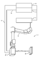
- FIG. 1 is a schematic configuration diagram of a laser processing system according to an embodiment.
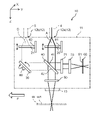
- FIG. 2 is a schematic configuration diagram showing the internal structure of the laser processing head.
- FIG. 3A is a schematic diagram showing changes in the beam diameter of the first laser light due to the aperture.
- FIG. 3B is a schematic diagram showing changes in the beam diameter of the second laser light due to the aperture.
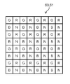
- FIG. 4 is a schematic diagram showing the pixel structure of the image sensor.
- FIG. 5 is a diagram showing an example of the relationship between light receiving efficiency of RGB pixels and wavelength.
- FIG. 6 is a schematic diagram showing the pixel structure of another image sensor.
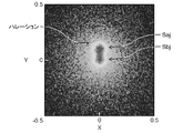
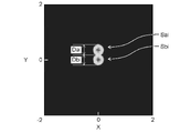
- FIG. 7A is an example of an image showing spots of the first laser beam and the second laser beam condensed on the light receiving surface of the image sensor.
- FIG. 7B is an example of an image showing spots of the first laser beam and the second laser beam condensed on the surface of the work.
- FIG. 8A is a view corresponding to FIG. 7A according to a comparative example.
- FIG. 8B is a view corresponding to FIG. 7B according to the comparative example.
- FIG. 9 is a schematic diagram showing the main part of the internal structure of the laser processing head according to the modification.
- FIG. 1 shows a laser processing system (laser processing apparatus) 1 according to this embodiment.
- the laser processing system 1 is a hybrid laser processing system using two types of laser beams with different wavelengths, and performs laser processing such as cutting, welding, and drilling of a work W.
- the laser processing system 1 includes a laser processing head (laser irradiation head) 10, a first laser oscillator 2 and a second laser oscillator 3, a first optical fiber 4 and a second optical fiber 5, a manipulator 6, and a control device 7. And prepare.
- a laser processing head laser irradiation head
- first laser oscillator 2 and a second laser oscillator 3
- first optical fiber 4 and a second optical fiber 5
- manipulator 6 and a control device 7. And prepare.
- the first laser oscillator 2 emits a first laser beam A.
- the second laser oscillator 3 emits a second laser beam B.
- the wavelengths of the first laser beam A and the second laser beam B are different from each other.
- the first laser beam A is near-infrared light and has a wavelength of approximately 900 nm to 1200 nm.
- the second laser beam B is blue light and has a wavelength of approximately 400 nm to 450 nm. In general, near-infrared light is applied to laser processing, but in recent years, blue light is also being applied to laser processing for reasons such as good absorption of copper.
- the second laser beam B may be green light (wavelength: approximately 450 nm to 550 nm).
- the first optical fiber 4 transmits the first laser beam A from the first laser oscillator 2 to the laser processing head 10 .
- the second optical fiber 5 transmits the second laser beam B from the second laser oscillator 3 to the laser processing head 10 .
- the laser processing head 10 irradiates the surface W1 of the workpiece W with at least one of the first laser beam A and the second laser beam B.
- the optical axis of the first laser beam A and the optical axis of the second laser beam B directed from the laser processing head 10 toward the workpiece W are made to be the same.
- the optical axis of the first laser beam A and the optical axis of the second laser beam B are superimposed.
- the workpiece W is irradiated in this state. Details of the laser processing head 10 will be described later.
- a laser processing head 10 is attached to the tip of the manipulator 6, and the laser processing head 10 is moved.
- a control device 7 controls the operation of the manipulator 6 and the oscillation of the laser beams A and B by the laser oscillators 2 and 3 .
- the control device 7 may control the operation of an actuator, which will be described later, inside the laser processing head 10 .
- FIG. 2 shows the internal structure of the laser processing head 10.
- X, Y, and Z in FIG. 2 indicate respective directions in an orthogonal coordinate system, with X and Y being the front, back, left, and right horizontal directions, and Z being the up and down direction (vertical direction).
- the direction in which the optical axes of the laser beams A and B (virtual light beams representing the luminous fluxes of the laser beams A and B) extend is referred to as the “optical axis direction”.
- the direction of the optical axis is not always constant in the orthogonal coordinate system X, Y, Z, and can change as the laser beams A, B travel.
- the laser processing head 10 converges the first laser beam A and the second laser beam B by a condensing optical system provided inside the housing 11 and irradiates the work W with the condensed light.
- the laser processing head 10 includes a first collimator lens 20, a second collimator lens 21, a bend mirror 30, a dichroic mirror 40, a work-side condenser lens 50, and an image as a photodetector as a condensing optical system.
- the housing 11 is provided with a first light inlet 12a and a second light inlet 12b on the upper side in the Z direction.
- the first light entrance port 12a and the second light entrance port 12b are provided with a predetermined gap therebetween.
- the first optical fiber 4 is connected to the first light entrance port 12a, and the first laser beam A enters the housing 11 through the first light entrance port 12a.
- the second optical fiber 5 is connected to the second light entrance 12b, and the second laser beam B is incident inside the housing 11 through the second light entrance 12b.
- the first light entrance 12a and the second light entrance 12b may be collectively referred to as the entrance portion 12 in some cases.
- the housing 11 is provided with a light irradiation port (irradiation section) 13 on the lower side in the Z direction.
- the first laser beam A and the second laser beam B are irradiated onto the surface W1 of the workpiece W through a protective glass (not shown) provided at the light irradiation port 13. As shown in FIG.
- the first collimating lens 20 converts the first laser beam A into parallel beams.
- the second collimator lens 21 converts the second laser beam B into parallel rays. They go straight in the Z direction parallel to each other.
- the bend mirror 30 directs the optical axis of the second laser beam B, which is parallel to the optical axis of the first laser beam A, in a direction intersecting the optical axis of the first laser beam A, specifically in a direction (Y direction ).
- the dichroic mirror 40 is a mirror that transmits most of the light in a specific wavelength range and reflects most of the light in other wavelength ranges.
- the dichroic mirror 40 transmits most of the first laser beam A incident from the back surface 41 side substantially straight to the front surface 42 side, and most of the second laser beam B incident from the surface 42 side. is reflected at a substantially right angle to the surface 42 side.
- the dichroic mirror 40 reflects the remainder of the first laser beam A incident from the rear surface 41 side toward the rear surface 41 side at a substantially right angle, and reflects the remainder of the second laser beam B incident from the front surface 42 side toward the rear surface 41 side. Penetrate almost straight.
- the light irradiation port 13 is arranged on the optical axis direction traveling side of most of the first laser beam A that has passed through the dichroic mirror 40 and most of the second laser beam B that has been reflected by the dichroic mirror 40 . That is, the dichroic mirror 40 transmits most of the first laser beam A to the work W side and reflects most of the second laser beam B to the work W side.
- the majority of the laser beams A and B is, for example, about 95% to 99.9% of the laser beams A and B before entering the dichroic mirror 40 in terms of energy.
- the remaining portions of the laser beams A and B are, for example, about 0.1% to 5% of the laser beams A and B before entering the dichroic mirror 40 in terms of energy.
- the work-side condenser lens 50 is arranged between the dichroic mirror 40 and the work W in the optical axis direction.
- the work-side condenser lens 50 condenses the first laser beam A and the second laser beam B, respectively.
- the condensed first laser beam A and second laser beam B are irradiated onto the surface W1 of the workpiece W through the light irradiation port 13, respectively.
- the work-side condenser lens 50 may have a chromatic aberration correction function. In this case, the condensing positions of the first laser beam A and the second laser beam B transmitted through the work-side condensing lens 50 substantially match in the Z direction.
- the image sensor (photodetector) 60 is an imaging device that photoelectrically converts the brightness and darkness of the light imaged on its light receiving surface 61 into an amount of charge, reads it out, and converts it into an electrical signal.
- the image sensor 60 is arranged on the back surface 41 side of the dichroic mirror 40 .
- the image sensor 60 is arranged on the traveling side of the remaining portion of the first laser beam A reflected by the dichroic mirror 40 and the remaining portion of the second laser beam B transmitted through the dichroic mirror 40 in the optical axis direction. That is, the image sensor 60 receives the remainder of the first laser beam A reflected by the dichroic mirror 40 and the remainder of the second laser beam B transmitted through the dichroic mirror 40 on the light receiving surface 61 .
- the aperture 71 is arranged between the dichroic mirror 40 and the detection-side condenser lens 70 in the optical axis direction. As will be described in detail later, the aperture 71 has a diameter of the first laser beam A and the second laser beam B (hereinafter referred to as the beam diameter of the first laser beam A and the second laser beam B are sometimes referred to as the beam diameter of .) can be reduced.
- the detection-side condenser lens 70 is arranged between the aperture 71 and the image sensor 60 in the optical axis direction.
- the detection-side condenser lens 70 condenses the first laser beam A and the second laser beam B, respectively. Then, the detection-side condenser lens 70 irradiates the light-receiving surface 61 of the image sensor 60 with the first laser beam A and the second laser beam B thus collected.
- the detection-side condenser lens 70 may have a chromatic aberration correction function. In this case, the condensing positions of the first laser beam A and the second laser beam B transmitted through the detection-side condensing lens 70 substantially coincide in the Y direction.
- the size and curvature of the detection side condenser lens 70, and the distance between the detection side condenser lens 70 and the image sensor 60 are determined so as to correspond to the condensed state of the first laser beam A irradiated onto the surface W1 of the workpiece W. is set. That is, the condensed state of the first laser beam A applied to the light receiving surface 61 of the image sensor 60 corresponds to the condensed state of the first laser beam A applied to the surface W1 of the workpiece W. As shown in FIG.
- the size and curvature of the detection-side condenser lens 70, the detection-side condenser lens 70 and the image sensor 60 are adjusted so as to correspond to the condensed state of the second laser beam B irradiated onto the surface W1 of the workpiece W. distance is set. That is, the condensed state of the second laser beam B applied to the light receiving surface 61 of the image sensor 60 corresponds to the condensed state of the second laser beam B applied to the surface W1 of the workpiece W.
- the spot diameter of the first laser beam A (detection side first spot diameter Daj) expands on the light receiving surface 61 of the image sensor 60
- the spot diameter of the first laser beam A irradiated onto the surface W1 of the workpiece W is (Work-side first spot diameter Dai) also increases.
- the focal position of the second laser beam B on the light receiving surface 61 of the image sensor 60 shifts, the focal position of the second laser beam B with which the surface W1 of the workpiece W is irradiated also shifts.
- the spot diameter means the diameter of the laser light on an arbitrary image plane (for example, the surface W1 of the workpiece W or the light receiving surface 61 of the image sensor 60), and does not necessarily mean the diameter of the laser light. It is not limited to the diameter at the light spot.
- the mirror-side actuator 80 changes the tilt of the bend mirror 30.
- the mirror-side actuator 80 is composed of, for example, a tilt axis and a motor that rotates the tilt axis.
- the tilt change of the bend mirror 30 by the mirror-side actuator 80 changes the direction of the optical axis of the second laser beam B bent by the bend mirror 30 . As a result, the condensing position of the second laser beam B changes.
- the first lens side actuator 81 moves the first collimating lens 20 in the optical axis direction (Z direction).
- the first lens side actuator 81 is composed of, for example, a linear motor.
- the second lens side actuator 82 moves the second collimating lens 21 in the optical axis direction (Z direction).
- the second lens side actuator 82 is composed of, for example, a linear motor.
- the collimator lenses 20 and 21 When the collimator lenses 20 and 21 are moved in the optical axis direction (Z direction) by the lens side actuators 81 and 82, the collimator lenses 20 and 21 necessarily move straight in the optical axis direction (Z direction). Instead, it may move or tilt slightly in the horizontal direction (X direction and Y direction) orthogonal to the optical axis direction.
- FIG. 3A schematically shows changes in the beam diameter of the first laser light due to the aperture
- FIG. 3B schematically shows changes in the beam diameter of the second laser light due to the aperture.
- the maximum aperture diameter of the aperture 71 is larger than each of the beam diameter ⁇ 1 of the first laser beam A and the beam diameter ⁇ 3 of the second laser beam B, as shown on the left side of FIG. 3A and the left side of FIG.
- the light A and the second laser light B enter the detection-side condenser lens 70 while maintaining the original beam diameters.
- the outputs of the first laser beam A and the second laser beam B used for laser processing are usually as large as several hundred W to several kW. Therefore, even if about 1% of them are incident on the image sensor 60, the power of the laser light irradiated onto the light receiving surface 61 reaches several watts to several tens of watts. In this case, the output is too large, and the image acquired by the image sensor 60 may be disturbed by halation or the like, or the color filter of the image sensor 60 may be burnt during long-term use.
- the size of the detection-side condenser lens 70 must be set such that the beam diameter ⁇ 1 or the beam diameter ⁇ 3 is within the effective collection diameter of the detection-side condenser lens 70 . If the beam diameter ⁇ 1 or the beam diameter ⁇ 3 is larger than a predetermined value, the size of the detection-side condenser lens 70 is increased.
- the beam diameters of the first laser beam A and the second laser beam B are reduced to ⁇ 2 ( ⁇ 2 ⁇ 1, ⁇ 3 ).
- the diameters of the first laser beam A and the second laser beam B incident on the detection-side condenser lens 70 are each reduced so that they fall within the effective beam diameter of the detection-side condenser lens 70 .
- the excess luminous fluxes of the first laser beam A and the second laser beam B can be blocked and made incident on the light receiving surface 61 of the image sensor 60 .
- the power of the first laser beam A and the second laser beam B incident on the light-receiving surface 61 can be reduced, thereby suppressing the above-described defects such as image distortion and color filter burn-in. .
- FIG. 4 schematically shows the pixel structure of the image sensor.
- FIG. 5 shows the relationship between light receiving efficiency and wavelength of RGB pixels.
- FIG. 6 schematically shows the pixel structure of another image sensor.
- the image sensor 60 includes pixels that receive near-infrared light or infrared light (hereinafter referred to as N pixels), pixels that receive red light (hereinafter referred to as R pixels), A pixel that receives green light (hereinafter referred to as a G pixel) and a pixel that receives blue light (hereinafter referred to as a B pixel) are arranged as a unit of a total of four pixels. Specifically, it is a color filter array in which one G pixel is replaced with an N pixel in contrast to the known Bayer array.
- the R pixel has a high quantum efficiency for photoelectric conversion of light with a wavelength band of about 600 nm to 850 nm, and efficiently converts normal red light (about 600 nm to 700 nm) into an electrical signal. Convert.
- the G pixel has a high quantum efficiency for photoelectrically converting light with a wavelength band of about 500 nm to 550 nm, and efficiently converts normal green light (about 500 nm to 550 nm) into an electrical signal.
- the B pixel has a high quantum efficiency for photoelectrically converting light with a wavelength band of about 400 nm to 500 nm, and efficiently converts normal blue light (about 420 nm to 480 nm) into an electrical signal.
- the N pixels have a high quantum efficiency for photoelectric conversion of light with a wavelength band of about 900 nm to 1200 nm, and efficiently convert near-infrared light or infrared light (about 900 nm to 1200 nm). Convert to electrical signal.
- the wavelength of the first laser beam A is approximately 900 nm to 1200 nm
- the wavelength of the second laser beam B is approximately 400 nm to 450 nm. Therefore, by using the image sensor 60 shown in FIG. 4, the first laser beam A and the second laser beam B transmitted through the detection-side condenser lens 70 can be reliably converted into electrical signals. By appropriately setting the size of each pixel, the two-dimensional distribution of each of the first laser beam A and the second laser beam B on the light receiving surface 61 can be grasped.
- the first laser beam A and the second laser beam B on the surface W1 of the workpiece W are determined based on the two-dimensional distribution and the spot diameters of the first laser beam A and the second laser beam B on the light receiving surface 61, respectively. 2
- the condensing position and spot diameter of the laser beam B can be corrected.
- the image sensor 60 has a plurality of first light receiving portions (N pixels) that receive light in a first wavelength band including the wavelength of the first laser light A, eg, 900 nm to 1200 nm.
- the image sensor 60 has a plurality of second light receiving portions (B pixels and/or G pixels) that receive light in a second wavelength band including the wavelength of the second laser beam B, for example, 400 nm to 600 nm.
- N pixels first light receiving portions
- B pixels and/or G pixels that receive light in a second wavelength band including the wavelength of the second laser beam B, for example, 400 nm to 600 nm.
- the state of convergence on the surface W1 of the workpiece W is monitored. can do.
- the mirror side actuator 80 is tilted.
- the condensing positions of the two laser beams can be matched.
- the first lens side actuator 81 is driven to eliminate the defocused state. By doing so, the first laser beam A can be focused on the surface W1 of the workpiece W. As shown in FIG.
- the second lens side actuator 82 is driven to eliminate the defocused state. By doing so, the second laser beam B can be focused on the surface W1 of the workpiece W. As shown in FIG.
- the laser processing head 10 has the housing 11 and a plurality of optical components arranged inside the housing 11 .
- the housing 11 has a first light entrance 12a into which the first laser beam A enters, a second light entrance 12b into which the second laser beam B enters, the first laser beam A and the second laser beam.
- a light irradiation port 13 for emitting B to the outside is provided.
- the second laser beam B has a shorter wavelength than the first laser beam A.
- a plurality of optical components are provided in the optical path of the second laser beam B, a bend mirror 30 that reflects the second laser beam B to change the optical path, and a bend mirror that is in the optical path of the first laser beam A and and a dichroic mirror 40 provided in the optical path of the second laser beam B reflected by 30 .
- the plurality of optical components include an aperture 71 provided in the optical path of the second laser beam B transmitted through the dichroic mirror 40 and in the optical path of the first laser beam A reflected by the dichroic mirror 40; and a detection-side condenser lens 70 provided in the optical paths of the first laser beam A and the second laser beam B that have passed through 71 .
- An image sensor (photodetector) 60 is arranged inside the housing 11 at a position capable of receiving the first laser beam A and the second laser beam B transmitted through the detection-side condenser lens 70 .
- the dichroic mirror 40 transmits most of the first laser beam A and directs it toward the light irradiation port 13 , and reflects the remainder of the first laser beam A toward the aperture 71 . Further, the aperture 71 reflects most of the second laser beam B toward the light irradiation port 13 and transmits the remainder of the second laser beam B toward the aperture 71 .
- the aperture 71 is configured to be able to reduce the diameters of the first laser beam A and the second laser beam B incident on the detection-side condenser lens 70 .
- the aperture 71 is a diaphragm jig for the first laser beam A and the second laser beam B.
- the thickness in the optical axis direction may be small, and the diameter direction of the laser beam (the Z direction in FIG. 2) may be small. may be of a size that allows the first laser beam A and the second laser beam B to pass therethrough.
- the diameter of the detection-side condenser lens 70 is increased so that the first laser beam A and the second laser beam B are contained within the effective diameter, it is necessary to change the curvature and the like. In the example shown in FIG. 2, the thickness in the Y direction may increase significantly.
- the diameters of the first laser beam A and the second laser beam B incident on the detection-side condenser lens 70 are respectively reduced, and the detection-side condenser lens 70, As a result, it is possible to suppress the laser processing head 10 from increasing in size.
- the excess luminous fluxes of the first laser beam A and the second laser beam B can be blocked and made incident on the light receiving surface 61 of the image sensor 60 .
- the power of the first laser beam A and the second laser beam B incident on the light-receiving surface 61 can be reduced, thereby suppressing the above-described defects such as image distortion and color filter burn-in. . This will be further explained.
- FIG. 7A shows an example of spot images of the first laser beam and the second laser beam focused on the light receiving surface of the image sensor
- FIG. 7B shows an example of the spot image of the first laser beam and the second laser beam focused on the surface of the work.
- An example of the spot image of a laser beam is shown.
- 8A shows a view corresponding to FIG. 7A according to the comparative example
- FIG. 8B shows a view corresponding to FIG. 7B according to the comparative example.
- 8A and 8B correspond to the case where the laser processing head 10 is not provided with the aperture 71 or the aperture 71 is not operated.
- the first laser beam A and the second laser beam B are aligned on the surface W1 of the workpiece W as shown in FIGS. 7B and 8B. or closely focused. Also, the workpiece-side first spot Sai of the first laser beam A and the workpiece-side second spot Sbi of the second laser beam B are both adjusted to have a size suitable for processing. The work-side first spot diameter Dai of the first laser beam A and the work-side second spot diameter Dbi of the second laser beam B are both adjusted to a size suitable for processing.
- the laser processing head 10 when the laser processing head 10 is not provided with the aperture 71, as described above, the powers of the first laser beam A and the second laser beam B incident on the light receiving surface 61 of the image sensor 60 are increased. Sometimes too much. In this case, for example, as shown in FIG. 8A, halation occurs on the photographing screen, and the first detection-side spot Saj of the first laser beam A and the second detection-side spot Sbj of the second laser beam A are clearly distinguished. difficult to separate and identify.
- the power and the diameter of each of the first laser beam A and the second laser beam B incident on the detection side condenser lens 70 can be adjusted appropriately. can be narrowed down to In this case, for example, as shown in FIG. 7A, the occurrence of halation or the like can be eliminated, and image distortion can be suppressed. Further, the detection-side first spot Saj of the first laser beam A and the detection-side second spot Sbj of the second laser beam A can be clearly separated and identified. A first detection spot diameter Daj of the first laser beam A and a second detection spot diameter Dbj of the second laser beam A can be measured.
- the first laser beam A and the second laser beam B are focused on the surface W1 of the workpiece W based on the images of the first laser beam A and the second laser beam B acquired by the image sensor 60. Position can be adjusted.
- a first collimator lens 20 is provided between the first light entrance 12a and the dichroic mirror 40 in the Z direction.
- a second collimating lens 21 is provided between the second light entrance 12b and the bend mirror 30.
- a work-side condenser lens 50 is provided between the dichroic mirror 40 and the light irradiation port 13 .
- the first collimating lens 20 collimates the first laser beam A and causes it to enter the dichroic mirror 40 .
- the second collimator lens 21 collimates the second laser beam B and makes it enter the bend mirror 30 .
- the work-side condensing lens 50 converges the first laser beam A and the second laser beam B that are incident on respective predetermined condensing positions.
- the optical axes of the first laser beam A and the second laser beam B traveling from the light irradiation port 13 toward the workpiece W can be substantially aligned.
- the first laser beam A and the second laser beam B can be focused on the surface W1 of the workpiece W, respectively.
- the condensing positions of the first laser beam A and the second laser beam B on the surface W1 of the workpiece W can be substantially matched.
- the image sensor (photodetector) 60 includes a plurality of first light receiving portions that receive light in a first wavelength band including the wavelength of the first laser beam A, and a plurality of light receiving portions in a second wavelength band including the wavelength of the second laser beam B. and a plurality of second light receiving portions for receiving light.
- the plurality of first light receiving portions and the plurality of second light receiving portions are periodically arranged on the light receiving surface 61 of the image sensor 60 .
- the image sensor 60 By configuring the image sensor 60 in this way, it is possible to acquire spot images of each of the first laser beam A and the second laser beam B with high resolution. As a result, the condensing positions of the first laser beam A and the second laser beam B on the surface W1 of the workpiece W can be precisely adjusted.
- the image sensor 60 preferably has a structure in which four pixels, each receiving near-infrared light, infrared light, red light, green light, and blue light, are periodically arranged on the light receiving surface 61 .
- This pixel structure is a known structure, and does not use a photodetector with a special structure, so the cost increase of the laser processing head 10 can be suppressed. Moreover, since the output signal of the image sensor 60 can be processed using a known signal processing device, it is possible to suppress an increase in signal processing load.
- a laser processing system (laser processing apparatus) 1 includes a laser processing head 10, a first laser oscillator 2 that emits a first laser beam A, and a second laser oscillator 3 that emits a second laser beam B. and at least.
- the laser processing system 1 also includes a first optical fiber 4 connected to a first light entrance port 12a and transmitting a first laser beam A emitted from a first laser oscillator 2 to a laser processing head 10; and a second optical fiber 5 that is connected to the entrance 12 b and transmits the second laser beam B emitted from the second laser oscillator 3 to the laser processing head 10 .
- the laser processing head 10 irradiates the workpiece W with at least one of the first laser beam A and the second laser beam B.
- the condensing positions of the first laser beam A and the second laser beam B on the surface W1 of the workpiece W can be substantially matched.
- the machining accuracy and the machining quality can be improved.
- the laser processing system 1 may further include a manipulator 6 that movably holds the laser processing head 10 . By doing so, it becomes easy to perform laser processing even on a workpiece W having a complicated structure.
- the laser processing system 1 collects the first laser beam A and the second laser beam B on the surface W1 of the workpiece W based on the images of the first laser beam A and the second laser beam B acquired by the image sensor 60. It is configured so that the light position can be adjusted. By doing so, it becomes easy to set the condensing positions of the first laser beam A and the second laser beam B on the surface W1 of the workpiece W to desired positions. As a result, it is possible to improve processing accuracy and processing quality during laser processing.
- FIG. 9 schematically shows the main part of the internal structure of the laser processing head according to this modification.
- the laser processing head 10 of this modified example shown in FIG. 9 differs from the laser processing head shown in FIG.
- the output of the first laser beam A and the second laser beam B may reach several kW.
- the first laser beam may still be detected on the light receiving surface 61 of the image sensor 60 .
- the power of the light A or the second laser light B may become too large.
- the power of the first laser beam A and the second laser beam B incident on the light receiving surface 61 of the image sensor 60 can be reduced by providing a neutral density filter 72 as shown in FIG.
- a neutral density filter 72 As a result, it is possible to reduce the occurrence of problems such as burn-in of the image sensor 60 . Further, even during long-term use, clear images of the first detection-side spot Saj of the first laser beam A and the second detection-side spot Sbj of the second laser beam B can be obtained.
- the characteristics of the light-attenuating filter 72 are set so as to attenuate the light having the same wavelength as the first laser beam A and the second laser beam B at a predetermined ratio.
- the first laser beam A is often set to have a higher output than the second laser beam B. Therefore, the light-attenuating filter 72 may attenuate only the light having the same wavelength as the first laser beam A. That is, the neutral density filter 72 is configured to reduce light having at least the same wavelength as the first laser light A. As shown in FIG.
- neutral density filter 72 may be arranged between the dichroic mirror 40 and the aperture 71, as indicated by the dashed line in FIG.
- the present disclosure is useful because it can be applied to a laser processing head and a laser processing system that emit laser beams with different wavelengths.
Landscapes
- Physics & Mathematics (AREA)
- Optics & Photonics (AREA)
- Engineering & Computer Science (AREA)
- Plasma & Fusion (AREA)
- Mechanical Engineering (AREA)
- Laser Beam Processing (AREA)
Priority Applications (4)
| Application Number | Priority Date | Filing Date | Title |
|---|---|---|---|
| CN202280026086.8A CN117120207A (zh) | 2021-04-02 | 2022-03-17 | 激光加工头以及具备该激光加工头的激光加工系统 |
| EP22780150.3A EP4316725B1 (en) | 2021-04-02 | 2022-03-17 | Laser machining head, and laser machining system comprising same |
| JP2023510928A JP7398623B2 (ja) | 2021-04-02 | 2022-03-17 | レーザ加工ヘッド及びこれを備えたレーザ加工システム |
| US18/464,223 US20230415260A1 (en) | 2021-04-02 | 2023-09-10 | Laser machining head, and laser machining system comprising same |
Applications Claiming Priority (2)
| Application Number | Priority Date | Filing Date | Title |
|---|---|---|---|
| JP2021063722 | 2021-04-02 | ||
| JP2021-063722 | 2021-04-02 |
Related Child Applications (1)
| Application Number | Title | Priority Date | Filing Date |
|---|---|---|---|
| US18/464,223 Continuation US20230415260A1 (en) | 2021-04-02 | 2023-09-10 | Laser machining head, and laser machining system comprising same |
Publications (1)
| Publication Number | Publication Date |
|---|---|
| WO2022209930A1 true WO2022209930A1 (ja) | 2022-10-06 |
Family
ID=83459110
Family Applications (1)
| Application Number | Title | Priority Date | Filing Date |
|---|---|---|---|
| PCT/JP2022/012128 Ceased WO2022209930A1 (ja) | 2021-04-02 | 2022-03-17 | レーザ加工ヘッド及びこれを備えたレーザ加工システム |
Country Status (5)
| Country | Link |
|---|---|
| US (1) | US20230415260A1 (https=) |
| EP (1) | EP4316725B1 (https=) |
| JP (1) | JP7398623B2 (https=) |
| CN (1) | CN117120207A (https=) |
| WO (1) | WO2022209930A1 (https=) |
Cited By (1)
| Publication number | Priority date | Publication date | Assignee | Title |
|---|---|---|---|---|
| CN117047261A (zh) * | 2023-09-04 | 2023-11-14 | 深圳公大激光有限公司 | 一种环形斑激光加工系统 |
Families Citing this family (1)
| Publication number | Priority date | Publication date | Assignee | Title |
|---|---|---|---|---|
| CN119927483A (zh) * | 2024-04-24 | 2025-05-06 | 深圳市创客工场科技有限公司 | 激光加工设备 |
Citations (5)
| Publication number | Priority date | Publication date | Assignee | Title |
|---|---|---|---|---|
| JPH10296468A (ja) * | 1997-04-24 | 1998-11-10 | Nikon Corp | レーザ加工装置 |
| JP2001018086A (ja) * | 1999-07-01 | 2001-01-23 | Nec Corp | レーザ加工装置および方法 |
| JP2009226473A (ja) | 2008-03-25 | 2009-10-08 | Amada Co Ltd | ファイバレーザ加工機における集光直径の変換制御方法及びその装置 |
| JP2014226473A (ja) | 2013-05-27 | 2014-12-08 | 京楽産業.株式会社 | 遊技機 |
| WO2018097018A1 (ja) * | 2016-11-22 | 2018-05-31 | パナソニックIpマネジメント株式会社 | レーザ加工装置及びレーザ加工方法 |
Family Cites Families (9)
| Publication number | Priority date | Publication date | Assignee | Title |
|---|---|---|---|---|
| JP2001196665A (ja) * | 2000-01-13 | 2001-07-19 | Hamamatsu Kagaku Gijutsu Kenkyu Shinkokai | 二波長レーザ加工光学装置およびレーザ加工方法 |
| WO2012173008A1 (ja) * | 2011-06-15 | 2012-12-20 | 株式会社日本製鋼所 | レーザ処理装置およびレーザ処理方法 |
| JP5802109B2 (ja) * | 2011-10-26 | 2015-10-28 | 浜松ホトニクス株式会社 | 光変調制御方法、制御プログラム、制御装置、及びレーザ光照射装置 |
| EP3051811A4 (en) * | 2013-09-26 | 2017-03-22 | Nikon Corporation | Image pickup element and image pickup device |
| JP6515999B2 (ja) * | 2015-03-30 | 2019-05-22 | 株式会社ニコン | 撮像素子および撮像装置 |
| JP6659617B2 (ja) * | 2017-04-12 | 2020-03-04 | 株式会社デンソー | 光検出器 |
| DE102018128266A1 (de) * | 2018-11-12 | 2020-05-14 | Eos Gmbh Electro Optical Systems | Verfahren und Vorrichtung zum Bestrahlen eines Materials mit einem Energiestrahl |
| DE102019109795B4 (de) * | 2019-04-12 | 2023-11-30 | Precitec Gmbh & Co. Kg | Vorrichtung und Verfahren zum Bestimmen einer Fokuslage sowie zugehöriger Laserbearbeitungskopf |
| JP2020199517A (ja) * | 2019-06-07 | 2020-12-17 | ファナック株式会社 | レーザ加工システム |
-
2022
- 2022-03-17 CN CN202280026086.8A patent/CN117120207A/zh active Pending
- 2022-03-17 JP JP2023510928A patent/JP7398623B2/ja active Active
- 2022-03-17 EP EP22780150.3A patent/EP4316725B1/en active Active
- 2022-03-17 WO PCT/JP2022/012128 patent/WO2022209930A1/ja not_active Ceased
-
2023
- 2023-09-10 US US18/464,223 patent/US20230415260A1/en active Pending
Patent Citations (5)
| Publication number | Priority date | Publication date | Assignee | Title |
|---|---|---|---|---|
| JPH10296468A (ja) * | 1997-04-24 | 1998-11-10 | Nikon Corp | レーザ加工装置 |
| JP2001018086A (ja) * | 1999-07-01 | 2001-01-23 | Nec Corp | レーザ加工装置および方法 |
| JP2009226473A (ja) | 2008-03-25 | 2009-10-08 | Amada Co Ltd | ファイバレーザ加工機における集光直径の変換制御方法及びその装置 |
| JP2014226473A (ja) | 2013-05-27 | 2014-12-08 | 京楽産業.株式会社 | 遊技機 |
| WO2018097018A1 (ja) * | 2016-11-22 | 2018-05-31 | パナソニックIpマネジメント株式会社 | レーザ加工装置及びレーザ加工方法 |
Non-Patent Citations (1)
| Title |
|---|
| See also references of EP4316725A4 |
Cited By (1)
| Publication number | Priority date | Publication date | Assignee | Title |
|---|---|---|---|---|
| CN117047261A (zh) * | 2023-09-04 | 2023-11-14 | 深圳公大激光有限公司 | 一种环形斑激光加工系统 |
Also Published As
| Publication number | Publication date |
|---|---|
| EP4316725A1 (en) | 2024-02-07 |
| JP7398623B2 (ja) | 2023-12-15 |
| US20230415260A1 (en) | 2023-12-28 |
| EP4316725B1 (en) | 2025-07-30 |
| EP4316725A4 (en) | 2024-10-23 |
| JPWO2022209930A1 (https=) | 2022-10-06 |
| CN117120207A (zh) | 2023-11-24 |
Similar Documents
| Publication | Publication Date | Title |
|---|---|---|
| EP0627643B1 (en) | Laser scanning optical system using axicon | |
| CN115121938B (zh) | 激光头监测模组、多波段激光光路系统及激光加工设备 | |
| US20230415260A1 (en) | Laser machining head, and laser machining system comprising same | |
| JP6873062B2 (ja) | レーザ加工ヘッド、および、レーザ加工ヘッドを備えたレーザ加工装置 | |
| US20220331911A1 (en) | Method for comparing laser processing systems and method for monitoring a laser processing process and associated laser processing system | |
| CN117120206B (zh) | 激光加工头以及激光加工系统 | |
| JP7344281B2 (ja) | 共焦点顕微鏡ユニット及び共焦点顕微鏡 | |
| US12533747B2 (en) | Laser processing head, laser processing system, and method of determining abnormality of laser processing system | |
| US4734570A (en) | Active focus detecting device with infrared source | |
| CN221225134U (zh) | 一种自动对焦装置及缺陷检测系统 | |
| JP7126062B2 (ja) | 調芯方法 | |
| JP2002156578A (ja) | 焦点検出装置、及びそれを備えた対物レンズ、光学顕微鏡又は光学検査装置 | |
| JP2022019571A (ja) | 光電センサの製造 | |
| JP3287318B2 (ja) | 光ビーム加熱装置 | |
| JP2023015417A (ja) | 走査型眼底撮影装置 | |
| JP2001083101A (ja) | 光学的パターン検査装置 | |
| CN120170243B (zh) | 一种不可见脉冲激光加工焦点的三点辅助定位方法及装置 | |
| JP2611411B2 (ja) | 光照射位置検出装置 | |
| CN117680716B (zh) | 一种激光选区熔化的同轴在线监测照明装置及增材制造设备 | |
| US20260014651A1 (en) | Sensor device for monitoring a laser machining process and laser machining system with the sensor device | |
| WO2026033014A1 (en) | Laser-based device and method for determining the focus position and/or for contrast determination | |
| KR20260053072A (ko) | 검사용 광학 장치, 결함 검사 장치, 조사 광학계, 및 검사 방법 | |
| JP2024009490A (ja) | レーザ加工装置 | |
| JPH04158320A (ja) | 焦点合わせ装置 | |
| JP2020146727A (ja) | レーザ加工装置 |
Legal Events
| Date | Code | Title | Description |
|---|---|---|---|
| 121 | Ep: the epo has been informed by wipo that ep was designated in this application |
Ref document number: 22780150 Country of ref document: EP Kind code of ref document: A1 |
|
| WWE | Wipo information: entry into national phase |
Ref document number: 2023510928 Country of ref document: JP |
|
| WWE | Wipo information: entry into national phase |
Ref document number: 2022780150 Country of ref document: EP |
|
| ENP | Entry into the national phase |
Ref document number: 2022780150 Country of ref document: EP Effective date: 20231102 |
|
| NENP | Non-entry into the national phase |
Ref country code: DE |
|
| WWG | Wipo information: grant in national office |
Ref document number: 2022780150 Country of ref document: EP |