WO2022209320A1 - 鋼板の材質予測モデルの生成方法、材質予測方法、製造方法、及び製造設備 - Google Patents
鋼板の材質予測モデルの生成方法、材質予測方法、製造方法、及び製造設備 Download PDFInfo
- Publication number
- WO2022209320A1 WO2022209320A1 PCT/JP2022/004876 JP2022004876W WO2022209320A1 WO 2022209320 A1 WO2022209320 A1 WO 2022209320A1 JP 2022004876 W JP2022004876 W JP 2022004876W WO 2022209320 A1 WO2022209320 A1 WO 2022209320A1
- Authority
- WO
- WIPO (PCT)
- Prior art keywords
- cooling
- steel sheet
- steel plate
- reference point
- steel
- Prior art date
Links
- 239000000463 material Substances 0.000 title claims abstract description 293
- 238000000034 method Methods 0.000 title claims abstract description 118
- 238000004519 manufacturing process Methods 0.000 title claims description 30
- 229910000831 Steel Inorganic materials 0.000 claims abstract description 656
- 239000010959 steel Substances 0.000 claims abstract description 656
- 238000001816 cooling Methods 0.000 claims abstract description 419
- 230000008569 process Effects 0.000 claims abstract description 68
- 239000000498 cooling water Substances 0.000 claims abstract description 57
- 238000010801 machine learning Methods 0.000 claims abstract description 29
- XLYOFNOQVPJJNP-UHFFFAOYSA-N water Substances O XLYOFNOQVPJJNP-UHFFFAOYSA-N 0.000 claims description 134
- 238000005259 measurement Methods 0.000 claims description 15
- 238000013528 artificial neural network Methods 0.000 claims description 9
- 238000003066 decision tree Methods 0.000 claims description 3
- 238000007637 random forest analysis Methods 0.000 claims description 3
- 239000007921 spray Substances 0.000 abstract description 3
- 238000010438 heat treatment Methods 0.000 description 96
- 238000012360 testing method Methods 0.000 description 81
- 230000000875 corresponding effect Effects 0.000 description 43
- 238000012546 transfer Methods 0.000 description 32
- 238000005098 hot rolling Methods 0.000 description 25
- 238000010586 diagram Methods 0.000 description 21
- 239000000203 mixture Substances 0.000 description 19
- 239000000126 substance Substances 0.000 description 16
- 238000005496 tempering Methods 0.000 description 16
- 238000010926 purge Methods 0.000 description 13
- 230000000452 restraining effect Effects 0.000 description 13
- 238000005096 rolling process Methods 0.000 description 13
- 238000011144 upstream manufacturing Methods 0.000 description 13
- 230000006870 function Effects 0.000 description 12
- 238000009826 distribution Methods 0.000 description 11
- 230000006399 behavior Effects 0.000 description 10
- 238000010791 quenching Methods 0.000 description 10
- 230000000171 quenching effect Effects 0.000 description 10
- 238000005070 sampling Methods 0.000 description 10
- 238000002347 injection Methods 0.000 description 9
- 239000007924 injection Substances 0.000 description 9
- 238000009529 body temperature measurement Methods 0.000 description 8
- 238000009864 tensile test Methods 0.000 description 8
- 238000005452 bending Methods 0.000 description 7
- 238000004364 calculation method Methods 0.000 description 7
- 230000000694 effects Effects 0.000 description 7
- 230000005855 radiation Effects 0.000 description 7
- 238000003303 reheating Methods 0.000 description 7
- 230000009466 transformation Effects 0.000 description 6
- 230000008859 change Effects 0.000 description 5
- 230000001276 controlling effect Effects 0.000 description 5
- 238000000275 quality assurance Methods 0.000 description 5
- 238000003860 storage Methods 0.000 description 5
- 125000004122 cyclic group Chemical group 0.000 description 4
- 238000009863 impact test Methods 0.000 description 4
- 230000006872 improvement Effects 0.000 description 4
- 230000009467 reduction Effects 0.000 description 4
- 230000004913 activation Effects 0.000 description 3
- 229910052782 aluminium Inorganic materials 0.000 description 3
- 238000004422 calculation algorithm Methods 0.000 description 3
- 229910052799 carbon Inorganic materials 0.000 description 3
- 238000007689 inspection Methods 0.000 description 3
- 229910052748 manganese Inorganic materials 0.000 description 3
- 229910052757 nitrogen Inorganic materials 0.000 description 3
- 229910052698 phosphorus Inorganic materials 0.000 description 3
- 229910052710 silicon Inorganic materials 0.000 description 3
- 238000005507 spraying Methods 0.000 description 3
- 239000002436 steel type Substances 0.000 description 3
- 240000007594 Oryza sativa Species 0.000 description 2
- 235000007164 Oryza sativa Nutrition 0.000 description 2
- 229910001563 bainite Inorganic materials 0.000 description 2
- 238000005422 blasting Methods 0.000 description 2
- 229910052804 chromium Inorganic materials 0.000 description 2
- 238000007730 finishing process Methods 0.000 description 2
- 239000012535 impurity Substances 0.000 description 2
- 229910052750 molybdenum Inorganic materials 0.000 description 2
- 229910001562 pearlite Inorganic materials 0.000 description 2
- 238000012545 processing Methods 0.000 description 2
- 230000002829 reductive effect Effects 0.000 description 2
- 235000009566 rice Nutrition 0.000 description 2
- 230000002123 temporal effect Effects 0.000 description 2
- 240000006829 Ficus sundaica Species 0.000 description 1
- 230000002159 abnormal effect Effects 0.000 description 1
- 229910045601 alloy Inorganic materials 0.000 description 1
- 239000000956 alloy Substances 0.000 description 1
- 238000005275 alloying Methods 0.000 description 1
- 229910001566 austenite Inorganic materials 0.000 description 1
- 230000008901 benefit Effects 0.000 description 1
- 238000009835 boiling Methods 0.000 description 1
- 238000013145 classification model Methods 0.000 description 1
- 238000004891 communication Methods 0.000 description 1
- 238000012669 compression test Methods 0.000 description 1
- 230000003750 conditioning effect Effects 0.000 description 1
- 230000008602 contraction Effects 0.000 description 1
- 238000007796 conventional method Methods 0.000 description 1
- 238000013527 convolutional neural network Methods 0.000 description 1
- 229910052802 copper Inorganic materials 0.000 description 1
- 230000002596 correlated effect Effects 0.000 description 1
- 230000001186 cumulative effect Effects 0.000 description 1
- 238000005520 cutting process Methods 0.000 description 1
- 230000003247 decreasing effect Effects 0.000 description 1
- 238000013135 deep learning Methods 0.000 description 1
- 230000007547 defect Effects 0.000 description 1
- 230000002542 deteriorative effect Effects 0.000 description 1
- 238000005516 engineering process Methods 0.000 description 1
- 238000009661 fatigue test Methods 0.000 description 1
- 239000007789 gas Substances 0.000 description 1
- 230000017525 heat dissipation Effects 0.000 description 1
- 230000001771 impaired effect Effects 0.000 description 1
- 238000003698 laser cutting Methods 0.000 description 1
- 230000000670 limiting effect Effects 0.000 description 1
- 238000007477 logistic regression Methods 0.000 description 1
- 229910000734 martensite Inorganic materials 0.000 description 1
- 239000003595 mist Substances 0.000 description 1
- 229910052759 nickel Inorganic materials 0.000 description 1
- 229910052758 niobium Inorganic materials 0.000 description 1
- 239000012299 nitrogen atmosphere Substances 0.000 description 1
- 230000002441 reversible effect Effects 0.000 description 1
- 238000010008 shearing Methods 0.000 description 1
- 238000004781 supercooling Methods 0.000 description 1
- 230000003746 surface roughness Effects 0.000 description 1
- 230000008685 targeting Effects 0.000 description 1
- 238000010998 test method Methods 0.000 description 1
- 229910052718 tin Inorganic materials 0.000 description 1
- 229910052721 tungsten Inorganic materials 0.000 description 1
- 229910052720 vanadium Inorganic materials 0.000 description 1
- 229910000859 α-Fe Inorganic materials 0.000 description 1
Images


Classifications
-
- B—PERFORMING OPERATIONS; TRANSPORTING
- B21—MECHANICAL METAL-WORKING WITHOUT ESSENTIALLY REMOVING MATERIAL; PUNCHING METAL
- B21C—MANUFACTURE OF METAL SHEETS, WIRE, RODS, TUBES OR PROFILES, OTHERWISE THAN BY ROLLING; AUXILIARY OPERATIONS USED IN CONNECTION WITH METAL-WORKING WITHOUT ESSENTIALLY REMOVING MATERIAL
- B21C51/00—Measuring, gauging, indicating, counting, or marking devices specially adapted for use in the production or manipulation of material in accordance with subclasses B21B - B21F
-
- B—PERFORMING OPERATIONS; TRANSPORTING
- B21—MECHANICAL METAL-WORKING WITHOUT ESSENTIALLY REMOVING MATERIAL; PUNCHING METAL
- B21B—ROLLING OF METAL
- B21B37/00—Control devices or methods specially adapted for metal-rolling mills or the work produced thereby
- B21B37/74—Temperature control, e.g. by cooling or heating the rolls or the product
-
- C—CHEMISTRY; METALLURGY
- C21—METALLURGY OF IRON
- C21D—MODIFYING THE PHYSICAL STRUCTURE OF FERROUS METALS; GENERAL DEVICES FOR HEAT TREATMENT OF FERROUS OR NON-FERROUS METALS OR ALLOYS; MAKING METAL MALLEABLE, e.g. BY DECARBURISATION OR TEMPERING
- C21D1/00—General methods or devices for heat treatment, e.g. annealing, hardening, quenching or tempering
- C21D1/56—General methods or devices for heat treatment, e.g. annealing, hardening, quenching or tempering characterised by the quenching agents
- C21D1/60—Aqueous agents
-
- C—CHEMISTRY; METALLURGY
- C21—METALLURGY OF IRON
- C21D—MODIFYING THE PHYSICAL STRUCTURE OF FERROUS METALS; GENERAL DEVICES FOR HEAT TREATMENT OF FERROUS OR NON-FERROUS METALS OR ALLOYS; MAKING METAL MALLEABLE, e.g. BY DECARBURISATION OR TEMPERING
- C21D11/00—Process control or regulation for heat treatments
- C21D11/005—Process control or regulation for heat treatments for cooling
-
- C—CHEMISTRY; METALLURGY
- C21—METALLURGY OF IRON
- C21D—MODIFYING THE PHYSICAL STRUCTURE OF FERROUS METALS; GENERAL DEVICES FOR HEAT TREATMENT OF FERROUS OR NON-FERROUS METALS OR ALLOYS; MAKING METAL MALLEABLE, e.g. BY DECARBURISATION OR TEMPERING
- C21D8/00—Modifying the physical properties by deformation combined with, or followed by, heat treatment
- C21D8/005—Modifying the physical properties by deformation combined with, or followed by, heat treatment of ferrous alloys
-
- C—CHEMISTRY; METALLURGY
- C21—METALLURGY OF IRON
- C21D—MODIFYING THE PHYSICAL STRUCTURE OF FERROUS METALS; GENERAL DEVICES FOR HEAT TREATMENT OF FERROUS OR NON-FERROUS METALS OR ALLOYS; MAKING METAL MALLEABLE, e.g. BY DECARBURISATION OR TEMPERING
- C21D8/00—Modifying the physical properties by deformation combined with, or followed by, heat treatment
- C21D8/02—Modifying the physical properties by deformation combined with, or followed by, heat treatment during manufacturing of plates or strips
- C21D8/0247—Modifying the physical properties by deformation combined with, or followed by, heat treatment during manufacturing of plates or strips characterised by the heat treatment
-
- C—CHEMISTRY; METALLURGY
- C21—METALLURGY OF IRON
- C21D—MODIFYING THE PHYSICAL STRUCTURE OF FERROUS METALS; GENERAL DEVICES FOR HEAT TREATMENT OF FERROUS OR NON-FERROUS METALS OR ALLOYS; MAKING METAL MALLEABLE, e.g. BY DECARBURISATION OR TEMPERING
- C21D9/00—Heat treatment, e.g. annealing, hardening, quenching or tempering, adapted for particular articles; Furnaces therefor
- C21D9/46—Heat treatment, e.g. annealing, hardening, quenching or tempering, adapted for particular articles; Furnaces therefor for sheet metals
-
- C—CHEMISTRY; METALLURGY
- C22—METALLURGY; FERROUS OR NON-FERROUS ALLOYS; TREATMENT OF ALLOYS OR NON-FERROUS METALS
- C22C—ALLOYS
- C22C38/00—Ferrous alloys, e.g. steel alloys
-
- G—PHYSICS
- G05—CONTROLLING; REGULATING
- G05B—CONTROL OR REGULATING SYSTEMS IN GENERAL; FUNCTIONAL ELEMENTS OF SUCH SYSTEMS; MONITORING OR TESTING ARRANGEMENTS FOR SUCH SYSTEMS OR ELEMENTS
- G05B13/00—Adaptive control systems, i.e. systems automatically adjusting themselves to have a performance which is optimum according to some preassigned criterion
- G05B13/02—Adaptive control systems, i.e. systems automatically adjusting themselves to have a performance which is optimum according to some preassigned criterion electric
- G05B13/0265—Adaptive control systems, i.e. systems automatically adjusting themselves to have a performance which is optimum according to some preassigned criterion electric the criterion being a learning criterion
-
- G—PHYSICS
- G06—COMPUTING; CALCULATING OR COUNTING
- G06N—COMPUTING ARRANGEMENTS BASED ON SPECIFIC COMPUTATIONAL MODELS
- G06N20/00—Machine learning
Definitions
- the present invention relates to a method for generating a material prediction model for steel sheets, a material prediction method, a manufacturing method, and manufacturing equipment.
- quenching refers to a steel sheet at a temperature equal to or higher than the Ac3 transformation point, which is the completion temperature of austenite transformation after hot rolling, and a steel sheet that has been cooled after rolling and then heated again to a temperature equal to or higher than the Ac3 transformation point in a heating furnace or the like. is rapidly cooled to a temperature below the martensitic transformation start temperature (Ms point) in a cooling facility.
- Quenching is widely used as a method of manufacturing particularly high-strength steel sheets.
- Direct quenching refers to quenching the rolled steel sheet without cooling or reheating it.
- a heat treatment process is also used in which the heated steel sheet is stopped cooling at about 500°C.
- a technique of cooling a steel sheet after hot rolling and stopping the cooling at a temperature of about 500° C. is called accelerated cooling, and is currently a common heat treatment process.
- After cooling the steel sheet after hot rolling to room temperature it is reheated, and cooling is stopped at a temperature of about 500 ° C. during cooling by the cooling equipment that cools the steel sheet after reheating. Technologies for controlling complex internal structures such as pearlite and bainite are also being developed.
- the in-plane material variation of the steel sheet may become a problem.
- a test piece is sampled from a portion of the manufactured steel plate to obtain a mechanical test value.
- the position where the test piece is taken may not necessarily represent the material of the entire surface of the steel sheet. Therefore, there is room for improvement in the uniformity of the material over the entire width of the steel sheet.
- Patent Document 1 describes a material quality assurance system for cooling equipment in a steel plate manufacturing line.
- This system includes a temperature collecting means for collecting temperature data of a steel plate to be cooled using temperature measuring means arranged at a plurality of positions such as an upstream position of a water cooling device, a cooling start position, and a cooling stop position. Based on the full-surface temperature map, the material quality of the thick steel plate is guaranteed.
- Patent Document 2 although it is intended for hot-rolled steel strips, a thermometer is placed in a steel strip production line including a cooling process to It describes a method of estimating the material property value for each mesh while referring to the degree of similarity with past operation data for each mesh that divides the longitudinal direction. Further, Patent Document 2 describes that an estimated value estimated using a heat transfer model from the temperature measurement value on the surface of the steel strip is used as temperature information inside the steel strip.
- Patent Document 3 describes a method of dividing the longitudinal direction of a steel strip into a plurality of regions and calculating the temperature history of the steel strip for each region from the cooling conditions for each region, targeting the cooling process of a hot-rolled steel strip. is described.
- the state of the microstructure in each region is predicted using the calculated temperature history, and the material property values of the steel strip are calculated using data related to past production results that are close to the predicted microstructure state.
- a method for predicting is described.
- Patent Document 3 when calculating the temperature history, a method of assuming that the temperature distribution in the thickness direction is uniform and a method of calculating the temperature distribution in the thickness direction by solving the heat conduction equation for the thickness direction It also describes how to
- Patent Document 1 collects the temperature data of the steel plate over the entire width of the steel plate when the steel plate is cooled. It cannot be predicted with high accuracy.
- the temperature data collected by the temperature collecting means is measurement data relating to the surface of the steel sheet, it may not necessarily represent the temperature history inside the steel sheet, and there is room for improvement in the accuracy of predicting the material of the steel sheet.
- the method described in Patent Document 2 sets a mesh that divides the steel strip in the thickness direction, and estimates the internal temperature of the steel strip using a heat transfer model.
- the heat transfer model in the steel strip cooling process usually solves a one-dimensional heat conduction equation in the thickness direction. becomes too large, making it difficult to use it as a practical temperature estimation means.
- the in-plane central part of the steel strip there is no practical problem even if the heat transfer in the longitudinal direction and the width direction of the steel strip is ignored. Heat transfer occurs in the longitudinal and width directions of the steel strip.
- the one-dimensional heat transfer model in the thickness direction with the surface temperature as the boundary condition has room for improvement in estimating the temperature history inside the steel strip with high accuracy.
- the method described in Patent Document 3 divides the steel strip in the thickness direction, estimates the temperature history inside the steel strip by solving the heat conduction equation in the thickness direction, and based on the estimated temperature history, each Predict the microstructure state of a region.
- the correspondence relationship with the material inside the steel strip is clarified in terms of predicting not only the temperature history but also the microstructure inside the steel strip. There is room for improvement in the accuracy of material prediction when heat transfer occurs in the longitudinal and width directions.
- the present invention has been made in view of the above problems, and an object of the present invention is to provide a steel sheet material prediction model capable of generating a steel sheet material prediction model that accurately predicts the material information of a steel sheet after passing through a cooling facility.
- a method for generating Another object of the present invention is to provide a method for predicting the quality of a steel sheet that can accurately predict the quality information of a steel sheet after it has passed through a cooling facility.
- Still another object of the present invention is to provide a steel plate manufacturing method and manufacturing equipment capable of manufacturing a steel plate having excellent uniformity of quality.
- a method for generating a steel sheet material prediction model according to the present invention includes a water cooling device that cools a steel plate by injecting cooling water onto the heated steel plate, and a temperature measuring device that measures the surface temperature of the steel plate during the cooling process.
- a method for generating a steel sheet material prediction model in a steel sheet cooling facility comprising: actual measurement data of the surface temperature at a reference point set in advance on the steel sheet, and surface temperature at the reference point set based on the reference point actual measurement data, a surface temperature information data set including input result data, and output result material information of the steel plate after passing through the cooling equipment at a position corresponding to the reference point on the steel plate corresponding to the input result data
- At least one reference point may be set at a position in the longitudinal direction of the steel plate and at least one at a position in the width direction with respect to the reference point.
- the material prediction model preferably includes an attribute information parameter selected from the attribute information of the steel plate as the input performance data.
- the material prediction model preferably includes, as the input performance data, at least one piece of operation performance data selected from the operation performance data of the water cooling device.
- machine learning it is preferable to use machine learning selected from neural network, decision tree learning, random forest, and support vector regression.
- a steel sheet material prediction method includes a water cooling device that cools a steel plate by injecting cooling water onto a heated steel plate, and a temperature measuring device that measures the surface temperature of the steel plate during the cooling process.
- a method for predicting the quality of a steel plate in a cooling facility, the surface temperature including a surface temperature at a prediction reference point set in advance on the steel plate and a surface temperature at a prediction reference point set based on the prediction reference point Using a material prediction model generated by machine learning, with the information data set as input data and the material information of the steel plate after passing through the cooling equipment at the position corresponding to the prediction reference point on the steel plate as output data. and predicting the material information of the steel sheet after passing through the cooling equipment.
- a method for manufacturing a steel sheet according to the present invention includes a step of determining whether the steel sheet after passing through the cooling equipment is acceptable, using the method for predicting the steel sheet material according to the present invention.
- a steel plate manufacturing facility includes a water cooling device that cools the steel plate by spraying cooling water onto the heated steel plate, and a temperature measuring device that measures the surface temperature of the steel plate during the cooling process. and a material prediction unit for outputting material information of the steel plate after passing through the cooling equipment, the material prediction unit predicting the surface temperature at a prediction reference point set in advance on the steel plate and the prediction reference Input data is a surface temperature information data set including surface temperature at a predicted reference point set based on the point, material information of the steel plate after passing through the cooling facility at a position corresponding to the predicted reference point on the steel plate is used as the output data to output the material information of the steel plate using a machine learning model.
- the method for generating a steel sheet material prediction model it is possible to generate a steel sheet material prediction model that accurately predicts the material information of the steel sheet after it has passed through the cooling equipment. Further, according to the steel sheet material prediction method according to the present invention, it is possible to accurately predict the material information of the steel sheet after it has passed through the cooling equipment. Further, according to the method and equipment for manufacturing a steel sheet according to the present invention, it is possible to manufacture a steel sheet with excellent uniformity of material quality.
- FIG. 1 is a diagram showing an example in which a steel sheet cooling facility, which is an embodiment of the present invention, is arranged in a steel sheet manufacturing facility that performs an on-line heat treatment process and an off-line heat treatment process.
- FIG. 2 is a diagram showing the configuration of a steel plate cooling facility that is an embodiment of the present invention when applied to an off-line heat treatment process.
- 3 is a diagram showing the configuration of the water cooling device shown in FIG. 2.
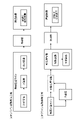
- FIG. FIG. 4 is a block diagram showing the configuration of the control computer shown in FIG.
- FIG. 5 is a diagram for explaining a method of associating the positional information of the steel sheet in the longitudinal direction with the surface temperature of the steel sheet.
- FIG. 6 is a diagram showing an example of measuring the surface temperature of a steel plate.
- FIG. 7 is a diagram showing an example of reference points.
- FIG. 8 is a diagram showing an example of reference points.
- FIG. 9 is a block diagram showing the configuration of a material prediction model generation unit that is an embodiment of the present invention.
- FIG. 10 is a diagram for explaining the operation of the steel sheet material prediction unit according to the embodiment of the present invention.
- FIG. 11 is a diagram showing an example of surface temperature information obtained by surface temperature measurement devices arranged at the inlet and outlet of cooling equipment.
- FIG. 12 is a diagram showing a display example of yield stress and tensile strength.
- FIG. 13 is a diagram showing a display example of cooling device inlet temperature, cooling device outlet temperature, tensile strength, and yield stress.
- FIG. 14 is a diagram showing an example of the relationship between actual values and predicted values of tensile strength and yield stress.
- FIG. 15 is a diagram showing the configuration of the hot rolling line in the example.
- FIG. 1(a) is a diagram showing an example in which a steel plate cooling facility, which is one embodiment of the present invention, is arranged in a hot rolling line that performs an on-line heat treatment process.
- a hot rolling line a slab, which is a cast piece, is heated to a predetermined heating temperature by heating equipment, and then reversed using one or two rolling mills. Carry out rolling.
- the steel sheet that has been rolled to a predetermined size by the rolling mill is conveyed from the rolling mill to a cooling facility while still at high temperature.
- the steel plate In the cooling equipment, the steel plate is cooled to a preset cooling stop temperature by accelerated cooling, and then the steel plate is cooled to near room temperature in a cooling bed (a yard for air-cooling the steel plate to near room temperature). Then, the steel sheet is transferred to a finishing facility. In the finishing facility, the shape of the steel sheet is corrected as necessary, and defect inspection, product sampling, and the like are performed.
- the steel sheet cooled by the cooling equipment in the on-line heat treatment process is subjected to a tempering process in which the steel sheet is reheated to a temperature of 140 to 680° C. before being conveyed to the cooling bed.
- the tempering process is different from the following off-line heat treatment process in that the steel sheet is not cooled using cooling equipment after the steel sheet is reheated.
- the finishing equipment is provided with a test piece picking device for picking a test piece sample for quality inspection from a steel plate that has been cooled to near room temperature.
- a test piece picking device is a device for picking a test piece sample from a predetermined position within a steel plate surface according to product standards, specifications, and the like.
- a laser cutting machine or a shearing machine is used as a test piece sampling device, and the sampled test piece is further processed into a test piece corresponding to the inspection item of the material test (for example, a JIS No. 4 test piece for a tensile test). processed into shape.
- FIG. 1(b) is a diagram showing an example in which cooling equipment for steel sheets, which is one embodiment of the present invention, is arranged in heat treatment equipment that performs an off-line heat treatment process.
- the off-line heat treatment process uses a steel sheet that has been rolled to a predetermined size in a hot rolling line.
- the hot rolling line has the same equipment configuration as above. However, the hot rolling line does not necessarily need to perform the on-line heat treatment process.
- the steel sheet rolled by the hot rolling line is cooled to near room temperature in the cooling bed, and then sent to the pretreatment facility.
- the pretreatment equipment is equipment for correcting the shape of the steel sheet and cutting it into predetermined dimensions as necessary prior to the off-line heat treatment process, and may perform descaling by shot blasting. However, the pretreatment in the pretreatment facility is not an essential step.
- the steel sheet is then transferred to a heat treatment facility that performs an off-line heat treatment process.
- the heat treatment equipment includes heating equipment, and after heating the steel plate to a predetermined temperature, cooling is performed by the cooling equipment. After the heat treatment, the steel sheet is air-cooled to near room temperature in the cooling bed, and then transported to the finishing facility.
- the conditioning equipment is similar to that used in the on-line heat treatment process.
- FIG. 2 is a diagram showing the configuration of steel plate cooling equipment, which is one embodiment of the present invention when applied to an off-line heat treatment process.
- the off-line heat treatment equipment 1 includes a heating furnace 2 for heating a steel plate S at a temperature of 100 ° C. or less to a predetermined temperature, a cooling equipment 3 for cooling the steel plate S heated in the heating furnace 2, and a cooling A control computer 10 for controlling the operation of the off-line heat treatment equipment 1 including the equipment 3 is provided as a main component.
- the cooling equipment 3 includes a water cooling device 4 that injects cooling water W onto the steel plate S, and a temperature measuring device 5 that measures the surface temperature of the steel plate S during the cooling process.
- the temperature measuring device 5 includes a temperature measuring device 51 installed on the upstream side of the water cooling device 4, a temperature measuring device 52 installed in the middle of the water cooling device 4, and a temperature measuring device 52 installed on the downstream side of the water cooling device 4.
- a temperature measuring device 53 is provided. However, it is sufficient if the temperature measuring device is installed at least one of the upstream side, midway point, and downstream side of the water cooling device 4 .
- the water cooling device 4 shown in FIG. 2 is equipment including water cooling nozzles 41a and 41b and restraint devices (restriction rolls 42a and 42b), but the restraint devices are not essential in this embodiment.
- a steel sheet S that has been hot-rolled to a predetermined thickness (eg, 30 mm) and width (eg, 2000 mm) in a hot rolling line located at a location different from the off-line heat treatment facility 1 and cooled to about room temperature. is loaded.
- the steel plate S is heated to a predetermined temperature (eg, 910° C.) in the heating furnace 2 .
- the steel sheet S extracted from the heating furnace 2 is sent to the cooling equipment 3 while being conveyed by a plurality of table rolls 6 installed on the delivery side of the heating furnace 2 .
- the cooling equipment 3 is drawn larger than the heating furnace 2 in order to explain the configuration of the cooling equipment 3 in detail.
- the length of the heating furnace 2 is about 60 to 80 m, and the length of the cooling equipment 3 is about 20 to 25 m. Therefore, when the front end of the steel plate S passes through the cooling equipment 3 , the stationary portion and the tail end of the steel plate S are positioned inside the heating furnace 2 .
- the steel plate S is extracted from the heating furnace 2 and conveyed at a substantially constant speed until cooling by the cooling equipment 3 is completed, so the cooling start temperature difference at the tip and tail ends of the steel plate S is small. . That is, assuming that the heating temperature of the steel plate S is T0, the distance from the heating furnace 2 to the water cooling device 4 of the cooling equipment 3 is L0, and the conveying speed of the steel plate S is V0, the leading end of the steel plate S is extracted at a temperature T0. It is cooled through the cooling time L0/V0. In the off-line heat treatment equipment 1, the distance L0 from the heating furnace 2 to the water cooling device 4 is short.
- the off-line heat treatment equipment 1 is advantageous for producing a thin steel plate with a small in-plane temperature deviation for a thin steel plate whose temperature tends to drop due to cooling, so that the uniformity of the steel plate quality is ensured. It has the advantage of being easy.
- the cooling equipment used in the online heat treatment process is different from the cooling equipment used in the offline heat treatment process.
- the stationary portion and the tail portion of the steel sheet S are left to cool. Therefore, the cooling time until the start of cooling is longer for the tail end of the steel plate S than for the tip end.
- FIG. 3 is a diagram showing the configuration of the water cooling device 4 shown in FIG.
- the water cooling device 4 includes a plurality of water cooling nozzles 41a and 41b that are arranged along the conveying direction of the steel sheet S so as to form pairs in the vertical direction of the steel sheet S.
- the water cooling nozzle 41a jets the cooling water W toward the upper surface of the steel plate S downward.
- the water cooling nozzle 41b jets the cooling water W upward toward the lower surface of the steel plate S.
- the water-cooled nozzles 41a and 41b constitute a pair of upper and lower water-cooled nozzles, and a cooling section using this as a unit is called a cooling zone, and a set of one or more cooling zones is called an area.
- the cooling area (the area to be water-cooled by the water cooling device 4) consists of six cooling zones, and in the example shown in FIG. 3, the cooling area consists of four cooling zones.
- the cooling area may be composed of a plurality of cooling zones, and the cooling zones may be separated by air-cooling sections in which no water-cooling nozzles are arranged.
- the water cooling nozzles 41a and 41b it is preferable that they have a cooling water flow rate adjustment valve and can adjust the amount of cooling water W sprayed toward the steel plate S. Thereby, the flow rate of the cooling water W injected for each cooling zone can be adjusted. Moreover, it is preferable that the amount of the cooling water W jetted toward the steel sheet S from the water-cooled nozzles 41a and 41b, which are paired vertically, can be adjusted to different values. The amount of cooling water W injected from each water-cooled nozzle is controlled for each water-cooled nozzle by the water-cooled flow control device 43 based on the water amount setting value set by the control computer 10 .
- the operating parameters of the water cooling device 4 include the amount of cooling water W jetted from at least a pair of water cooling nozzles 41a and 41b (cooling water amount) and the speed of the steel sheet S conveyed by the table rolls 6 (conveying speed).
- cooling water amount the amount of cooling water increases, the cooling rate and the amount of temperature drop of the steel sheet S can be increased.
- the smaller the conveying speed of the steel sheet S the larger the amount of temperature decrease of the steel sheet S can be.
- the cooling stop temperature and cooling rate are controlled as cooling conditions for obtaining a desired material quality.
- the operating parameters of the water cooling device 4 include the balance of the amount of cooling water for each cooling zone (for example, increasing the amount of cooling water in the cooling zone on the upstream side and decreasing the amount of cooling water in the cooling zone on the downstream side). is included. This is because the cooling rate can be controlled according to the temperature range of the steel sheet S.
- the balance of the amount of cooling water for each cooling zone can be represented by the ratio of the amount of cooling water injected in each cooling zone.
- the number of cooling zones into which cooling water W is injected may be changed. Different cooling stop temperatures can be controlled with the same cooling rate depending on the number of cooling zones used.
- the cooling zones to be used may be specified using codes or numerical values for determining whether each cooling zone is used or not, and these codes or numerical values may be used as operation parameters of the water cooling device 4 .
- the material of the steel sheet S can be controlled by adjusting the cooling rate by adjusting the amount of cooling water.
- a slit-type nozzle capable of uniformly spraying a large amount of cooling water W in the width direction of the steel sheet S, or a flat spray nozzle can be used.
- a multi-hole jet nozzle or a mist nozzle may be used.
- the water-cooled nozzles 41a and 41b do not necessarily have to be able to adjust the amount of cooling water for each water-cooled nozzle. This is because when the water cooling device 4 has a plurality of cooling zones, the cooling conditions can be changed by changing the number of cooling zones into which the cooling water W is injected.
- the water cooling device 4 may include a restraining device having at least a pair of restraining rolls that restrain the steel sheet S during cooling, together with the water cooling nozzles 41a and 41b. By restraining the strain of the steel sheet S that may occur when the steel sheet S is water-cooled, it is advantageous in maintaining the uniformity of cooling and ensuring the uniformity of the material of the steel sheet S.
- the configuration of the restraint device will be described with reference to FIG.
- the restraint device is placed in the cooling area and installed adjacent to the water cooling zone.
- the constraining rolls 42a and 42b constituting the constraining device are arranged such that the axial direction of the constraining rolls is substantially perpendicular to the conveying direction of the steel plate S so that the steel plate S is constrained by a pair of upper and lower rolls. there is The steel plate S undergoes strain due to thermal contraction and phase transformation during cooling by the water cooling device 4, but the restraint rolls 42a and 42b prevent the steel plate S from buckling due to such strain.
- the restraining device can also function as a draining roll.
- the temperature measuring device 5 is installed in the cooling equipment 3, it is possible to prevent the water on the upper surface of the steel plate S from disturbing the temperature measurement on the downstream side of the restraining device.
- the drainage purge nozzle 7 is installed on the output side of the most downstream restraining device.
- the draining purge nozzle 7 is angled toward the constraining roll 42a so that the cooling water W leaking from the gap formed at the contact portion between the constraining roll 42a and the steel plate S does not flow further downstream. Inject.
- the drainage purge 7a has the effect of suppressing the temperature deviation of the steel sheet S from increasing and suppressing the uniformity of the material of the steel sheet S from deteriorating.
- the control computer 10 receives information from the host computer 11 such as the heating temperature, thickness, width, and weight of the steel sheet S, as well as the target range of the cooling stop temperature (target cooling stop temperature) necessary to obtain the desired material quality. and the target range of cooling rate (target cooling rate). Then, the control computer 10 calculates operating conditions for realizing such conditions and determines operating parameters for each device of the water cooling device 4 .
- FIG. 4 is a block diagram showing the configuration of the control computer 10 shown in FIG.
- the control computer 10 acquires attribute information of the steel sheet S to be heat-treated from the host computer 11 .
- the attribute information of the steel sheet S includes information on the dimensions of the steel sheet S such as the thickness, width, length, and weight of the steel sheet S, as well as information on the chemical composition of the steel sheet S (the C content of the steel sheet S, the Si content content, Mn content, Cr content, Mo content, etc.) and target values of the mechanical properties of the steel sheet S after heat treatment (yield stress, tensile strength, elongation, toughness, hardness, etc.).
- the control computer 10 acquires information about the target cooling stop temperature and the target cooling rate from the host computer 11 in addition to the attribute information of the steel plate S. Then, the control computer 10 performs heat transfer calculation based on the internal model in the water cooling condition calculation unit 10a, and the water cooling nozzles in the cooling area are adjusted so as to satisfy the target cooling stop temperature and target cooling rate set as the cooling conditions.
- the operating conditions of the water cooling device 4 including the flow rate of the cooling water W of 41a and 41b, the cooling zone for spraying the cooling water W, and the conveying speed of the steel plate S within the cooling equipment 3 are determined.
- the operating conditions of the water cooling device 4 set by the water cooling condition calculation unit 10 a are sent to the water cooling flow control device 43 .
- the water cooling flow rate control device 43 controls the operating pressure and the number of operating cooling water pumps, the number of headers provided on the upstream side of the piping system of the water cooling nozzles 41a and 41b, the opening degree of the flow control valve, and the table roll 6.
- a command for the rotation speed of the motor is generated, and the operating conditions for the water cooling device 4 are set.
- the control computer 10 also sets operating conditions for them.
- the cooling equipment 3 of this embodiment has a temperature measuring device 5 that measures the surface temperature of the steel sheet S during the cooling process.
- the temperature measuring device 51 on the upstream side of the water cooling device 4 is installed at a position approximately 1 to 2 m away from the inlet of the water cooling device 4 . This is for measuring the cooling start temperature in the heat treatment process of the steel sheet S.
- the temperature measuring device 53 on the downstream side of the water cooling device 4 is installed at a position approximately 5 to 10 m away from the outlet of the water cooling device 4 . This is for measuring the cooling stop temperature in the heat treatment process of the steel sheet S.
- the inlet of the cooling equipment 3 coincides with the inlet of the water cooling device 4 .
- the outlet of the cooling equipment 3 coincides with the outlet of the water cooling device 4 .
- the temperature measuring device 5 used in this embodiment has a function of measuring the surface temperature of the steel sheet S during the cooling process.
- the cooling process is the process of temperature change of the steel sheet S occurring between the inlet and outlet of the cooling equipment 3 . Therefore, the temperature measuring device 5 may be installed at any position between the inlet and the outlet of the cooling equipment 3 .
- a temperature measuring device 52 is arranged behind the three zones on the upstream side of the water cooling device 4. ing.
- the temperature measuring device 52 between cooling zones may be installed at any position from the inlet to the outlet of the water cooling device 4 , and two or more temperature measuring devices may be arranged in the water cooling device 4 .
- the temperature measuring device 5 may measure the surface temperature of the upper surface of the steel plate S or the surface temperature of the lower surface.
- a contact type or a non-contact type may be used.
- a thermocouple is preferred for the contact type, and a radiation thermometer is preferred for the non-contact type.
- the radiation thermometer is a normal radiation thermometer that specifies the emissivity of the steel sheet S in advance and converts the brightness data into temperature data.
- a dichroic radiation thermometer that converts to may be used.
- a more preferred embodiment is a temperature measuring device capable of measuring the temperature distribution in the width direction of the steel sheet S.
- a method of arranging a plurality of radiation thermometers in a direction orthogonal to the conveying direction (longitudinal direction) of the steel sheet, or a scanning thermometer that scans temperature measurement points in the width direction can be used.
- a camera-type thermometer that obtains an image of the steel plate S and converts the luminance data of the image into temperature may be used.
- the temperature measuring device 5 It is preferable to install the temperature measuring device 5 at a position where it is less likely to be affected by the cooling water W from the water cooling nozzles 41a and 41b.
- the temperature measuring device 52 is partitioned by the restraint rolls 42a and 42b and arranged at a position where the cooling water W from the water cooling nozzles 41a and 41b is not directly supplied. Thereby, disturbance to the temperature measurement by the temperature measuring device 52 can be reduced.
- a temperature measuring device such as a steel plate thermometer in the cooling zone (Fountain Pyrometer) that can measure the surface temperature of the steel plate S even if the cooling water W is present, the cooling water W is directly supplied.
- a temperature measuring device 52 may be placed at a position where the temperature is measured.
- the surface temperature of the steel sheet S measured by the temperature measuring device 5 is associated with positional information within the plane of the steel sheet S.
- the width direction positions for acquiring the temperature data from the radiation thermometers are specified in advance. The correspondence with the position in the width direction of the steel plate S is clear.
- the positional information of the steel plate S in the longitudinal direction it is possible to associate it with the temperature data acquired by the temperature measuring device 5 by specifying the conveying distance from the tip of the steel plate S.
- the temperature measuring device 5 when the temperature measuring device 5 is arranged as shown in FIG. 5, it can be determined that the tip of the steel plate S reaches the temperature measuring device 5 by the stepwise increase of the measured temperature data. Then, using the signal that the tip of the steel plate S reaches the temperature measuring device 5 as a trigger, the subsequent conveying distance is calculated from the number of rotations and the diameter of the table roll 6 that conveys the steel plate S, and this is the distance from the tip of the steel plate S. This is positional information in the longitudinal direction.
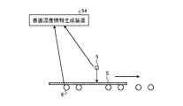
- the measured value of the surface temperature of the steel plate S measured by the temperature measuring device 5 and the positional information in the longitudinal direction are sent to, for example, the surface temperature information generating device 54, and the measured value of the surface temperature of the steel plate S is the position in the plane of the steel plate. Associated with information.
- the method of associating the surface temperature of the steel sheet S with the positional information in the plane of the steel sheet S is not limited to such a method, and a case where the entire surface of the steel sheet S is measured by a camera-type two-dimensional thermometer. Since the temperature and positional information on the entire surface of the steel plate S are obtained in , the surface temperature of the steel plate S and the positional information on the surface of the steel plate S are obtained at the same time.
- FIG. 6 shows an example of measuring the surface temperature of the steel plate S.
- the surface temperature information in the plane of the steel sheet S is associated with the measured temperature and the position information in the plane of the steel sheet S. Then, the surface temperature information associated with the position information is sent to the control computer 10 or the host computer 11 and stored in at least one of the storage devices.
- the temperature measurement device 5 installed in the cooling equipment 3 is used to measure the surface temperature data at the reference point preset on the steel sheet S, and the reference point Acquire actual measurement data of the surface temperature at the reference point set based on The measured surface temperature data of the acquired reference points and reference points are hereinafter referred to as a surface temperature information data set.
- a reference point in the present embodiment is a point that is arbitrarily set in the plane of the steel sheet S to be cooled and whose position in the plane of the steel sheet S is specified. That is, the reference point is a point whose position is specified by the distance from the in-plane front end or tail end of the steel plate S and the distance from one width direction end or the other width direction end of the steel plate S. be.
- Fig. 7 shows an example of reference points.
- the reference point PA is the point whose position is specified by the coordinates (x1, y1).
- a plurality of reference points may be set for one steel plate S.
- the planar shape of the steel plate S is not necessarily a rectangular shape, the central portion in the width direction of the tip end portion of the steel plate S is removed so as to exclude the region where the width drop occurs at the tip end portion of the steel plate S.
- a coordinate system is set with the origin being a position a predetermined distance Lt (for example, Lt can be set to about 0.05 to 0.3 m) in the direction of the tail end. Since the region where the leading edge portion of the steel plate S is reduced in width does not become a steel plate product, it may be excluded from the target region for material quality prediction of the steel plate S in the present embodiment.
- Lt a predetermined distance
- a reference point is a point that is set based on a reference point, and that has a specified positional relationship with the reference point in the steel plate plane.
- a plurality of reference points may be set with respect to one reference point.
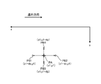
- FIG. 8 shows an example of reference points.
- Reference points PB1 and PB2 are set on the tail end side and the tip end side, which are separated by a distance dx in the traveling direction from the reference point PA specified by the coordinates (x1, y1).
- reference points PB3 and PB4 are set on the right and left sides in the direction of travel separated by a distance dy in the width direction.
- At least one reference point may be set with respect to one reference point, and may be set in either the advancing direction or the width direction of the steel plate S. Moreover, the reference point may be set at a position having a certain angle with respect to the advancing direction of the steel sheet S, and does not necessarily have to be set in the advancing direction and the width direction of the steel sheet S. However, it is preferable to set the reference points in both the traveling direction and the width direction of the steel sheet S with respect to the reference point, and it is more preferable to set two or more reference points in each direction.
- the distance between the reference point and the reference point can be arbitrarily set within the range of 0.1 to 200 mm. It is preferably 1 to 50 mm, more preferably 5 to 20 mm.
- the distance between the reference point and the reference point may be changed according to the plate thickness of the steel plate S. For example, with respect to the plate thickness H of the steel plate S, the distance between the reference point and the reference point may be set within the range of 0.5H to 3.0H.
- the behavior of heat transfer inside the steel sheet is indirectly specified by the difference in surface temperature measured at the reference point and the reference point, so the distance between the reference point and the reference point is too short. and the difference in surface temperature between the two becomes difficult to detect.
- the distance between the reference point and the reference point may be set according to the target cooling rate. For example, when the target cooling rate is high, the distance between the reference point and the reference point may be shortened, and when the target cooling rate is low, the distance between the reference point and the reference point may be lengthened.
- the surface temperature of the steel sheet S is associated with the in-plane positional information by the temperature measuring device 5 as described above. Therefore, based on the position information of the reference point and the reference point, the surface temperature data of the reference point and the reference point can be specified, thereby forming the surface temperature information data set.
- a method for generating a steel sheet material quality prediction model which is an embodiment of the present invention, includes the above-described surface temperature information data set in input actual data, and at a position corresponding to a reference point on steel sheet S corresponding to this input actual data, The material information of the steel sheet S after passing through the cooling equipment 3 is used as actual output data.
- the performance data of the material information of the steel plate S is obtained from the steel plate S after passing through the cooling equipment 3, and can be obtained from the steel plate S after it has been cooled to near room temperature.
- the material information can be acquired from the steel sheet S at the stage of being conveyed to the cooling bed after passing through the cooling equipment 3 or to the finishing equipment.
- a test piece sample for obtaining material information is taken by a test piece sampling device of the finishing facility.
- test items for inspecting the quality of the steel sheet S and sampling positions of test piece samples are set in advance.
- the sampling position of the test piece sample is often set and specified in advance according to the size, standard, and specification of the steel plate S. Therefore, the material information of the steel plate S is acquired in association with the position information of the steel plate S.
- FIG. 1( a ) when the steel sheet cooled by the cooling equipment is transferred to the cooling bed through the tempering process for reheating, the actual data of the material information of the steel sheet S is obtained from the steel sheet S after tempering. This is because, in the tempering process, although the steel sheet S is not cooled using cooling equipment, the material information of the steel sheet S changes due to the tempering process.
- the material information of the steel sheet S refers to information relating to the mechanical properties of the steel sheet S manufactured through the heat treatment process.
- Information on mechanical properties means information obtained from tests normally performed to specify the mechanical properties of steel sheet S, such as tensile tests, compression tests, bending tests, Charpy impact tests, CTOD tests, DWTT tests, and fatigue tests. point to In the case of a tensile test, tensile strength, yield strength, elongation (permanent elongation, elongation at break, total elongation, etc.) can be used as information based on standards such as JIS and ISO.
- the upper yield point, lower yield point, 0.2% yield strength, and area of reduction are also information obtained from the tensile test, and therefore serve as material information of the steel sheet S.
- a V-notch test piece is taken from the test piece sample, and the absorbed energy and brittle fracture surface rate when broken by a pendulum type hammer, which are obtained for each test temperature, are measured. can be information.
- the crack tip opening amount (critical CTOD value) at which unstable fracture occurs can be used as the material information of the steel sheet S, which is acquired for each test temperature.
- the number of repetitions to fracture and the value of the fatigue limit acquired for each set stress amplitude may be used as the material information of the steel sheet S.
- test piece samples are obtained from a plurality of positions on the steel plate S
- material information is obtained for each test piece sampling position corresponding to the test piece sampling positions in the plane of the steel plate S.
- a plurality of test piece samples are taken from the same portion of the steel plate S
- a plurality of types of material information can be obtained using each test piece.
- the material information of the steel plate S can be obtained by making a data set of a plurality of acquired material information.
- a steel sheet material quality prediction apparatus includes a material quality prediction model generation unit.
- the material prediction model generation unit includes actual measurement data of the surface temperature at a reference point set in advance on the steel sheet S in the cooling equipment 3 and actual measurement data of the surface temperature at a reference point set based on the reference point.
- the surface temperature information data set is used as input actual data
- the material information of the steel sheet S after passing through the cooling equipment 3 at the position corresponding to the reference point on the steel sheet S corresponding to these input actual data is used as the output actual data.
- a material prediction model of the steel sheet S after passing through the cooling equipment 3 is generated by machine learning using a plurality of learning data.
- the material information of the steel sheet S after passing through the cooling equipment 3 which is the actual output data, is not necessarily limited to the material information after cooling to room temperature as long as it is after passing through the cooling equipment 3 .
- the tempering process of reheating the steel sheet S after passing through the cooling equipment 3 is executed, the material information of the steel sheet S after the completion of the tempering process is used as the actual output data.
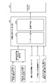
- Fig. 9 shows the configuration of the material prediction model generation unit, which is one embodiment of the present invention.
- the material prediction model generation unit 20 which is one embodiment of the present invention, includes a database unit 20a and a machine learning unit 20b.
- the database unit 20a acquires the measured surface temperature data at the reference point on the steel sheet S and the measured surface temperature data at the reference point associated with the reference point as actual values of the surface temperature information data set, The material information of the steel sheet S after passing through the cooling equipment 3 at the position corresponding to the reference point is acquired.
- the surface temperature information data set stored in the database unit 20a is surface temperature information data corresponding to the position where the material information is acquired as the reference point on the steel sheet S. Therefore, when there are a plurality of positions on one steel plate S for acquiring the material information of the steel plate S, the surface temperature information data set corresponding to each reference point and the material information are associated with each other and stored in the database unit 20a. accumulate. That is, the number of data sets stored in the database unit 20a is the same as the number of reference points from one steel plate S.
- the actual data of the material information of the steel plate S is obtained by specifying the position information in the plane of the steel plate as the position where the test piece sample was taken as described above.
- the test piece sample for acquiring the material information of the steel sheet S has a certain size depending on the test method, it does not strictly match the position of the reference point that constitutes the surface temperature information data set.
- the actual data of the material information of the steel sheet was acquired in this embodiment as well. Exact matching between the positions and the reference points that make up the surface temperature information data set is not required.
- the above-mentioned "position corresponding to the reference point on the steel plate” is defined as long as the coordinates specified in the plane of the steel plate S of the reference point are included in the range of the test piece sample picked up by the test piece picking device. good.
- the center of the position where the test piece for acquiring the material information is taken is within 200 mm from the reference point forming the surface temperature information data set.
- the attribute information of the steel sheet S includes information on the dimensions of the steel sheet S such as the thickness, width, length, and weight of the steel sheet S, as well as information on the chemical composition of the steel sheet S (the C content of the steel sheet S , Si content, Mn content, Cr content, Mo content) and target values of the mechanical properties of the steel sheet S after heat treatment (yield stress, tensile strength, elongation, toughness, hardness, etc.).
- the information on the chemical composition of the steel sheet S may include the contents of C, Si, Mn, Cr, and Mo, as well as the contents of Nb, Ni, V, W, Sn, and Cu.
- a plurality of reference points are set for one steel plate S, and a plurality of surface temperature information data sets are set. Even when the measured values are obtained, the attribute information parameters of the same steel plate S are associated with those surface temperature information data sets.
- the reason why the attribute information parameters of the steel sheet S are used to generate the material prediction model is that even if the attribute information of the steel sheet S changes greatly, it is advantageous in that a highly accurate material prediction model can be generated.
- the database unit 20a may store performance data (operation performance data) of the operation performance parameters of the water cooling device 4.
- the operation performance parameters of the water cooling device 4 are the amount of cooling water W injected from the water cooling nozzles 41a and 41b (cooling water amount), the speed of the steel plate S by the table roll 6 (conveyance speed), and the cooling zone of the cooling water amount.
- Set values or measured values of operation parameters that affect the cooling state of the steel plate S such as information on the balance of each cooling water W and the number of cooling zones in which the cooling water W is injected, can be used. This is because the cooling state of the steel sheet S affects the quality of the steel sheet S after cooling.
- the ratio of the upper and lower water amounts of the cooling water W injected from the water cooling nozzles 41a and 41b may be used as the operation result parameter of the water cooling device 4.
- FIG. This is because the steel sheet S is warped depending on the ratio of the upper and lower water amounts of the cooling water W, and the cooling state of the steel sheet S is affected.
- the amount of cooling water for each water cooling nozzle can be determined by the water cooling device 4.
- Operation performance data can be used.
- the sum of the amounts of cooling water in the water cooling zone or the sum of the amounts of cooling water in a plurality of water cooling zones arbitrarily selected from the water cooling zones may be used as the actual operation data of the water cooling device 4 .
- the plurality of cooling zones on the front side (upstream side) of the cooling area the temperature change of the steel sheet S is large, and the material quality of the steel sheet S is greatly affected.
- the sum of the cooling water amounts may also be used.
- the operation performance data of the water-cooling device 4 can be obtained by the flowmeters. You may use the performance data obtained.
- the set value of the cooling water amount set in the water cooling condition calculation section 10a may also be used. This is because if the set value and the actual value of the water cooling nozzle are compared in advance, it is considered that the actual amount of cooling water is less likely to greatly deviate from the set value.
- the cooling speed of the steel plate S and the conveying speed of the steel plate S in the cooling equipment 3 may be used as the operation performance data of the water cooling device 4 .
- the temperature gradient generated in the longitudinal direction of the steel sheet S changes depending on the cooling rate of the steel sheet S, and the shape of the steel sheet S changes due to the gradient of thermal strain in the longitudinal direction. This is because the quality of the steel sheet S after passing through the equipment is affected.
- the cooling stop temperature of the steel plate S may be included as the operation performance data of the water cooling device 4. This is because, when the cooling stop temperature is low, the steel sheet enters the cooling region of nucleate boiling, which is a condition in which temperature deviation is likely to occur, and the uniformity of the material in the plane of the steel sheet S may deteriorate.
- At least one of the conveying speeds of the steel plate S is preferably included, and it is more preferable to include a plurality of operational performance data among these. This is because it is advantageous for predicting the in-plane material distribution of the steel sheet S caused by a plurality of causes.
- the average value or the like in the plane of the steel plate S is calculated, and the calculated value can be used as the operation performance data of the water cooling device 4 as a representative value.
- the same representative value is associated with each surface temperature information data set as the operation performance data of the water cooling device 4. be done.
- the cooling process of the steel plate S when the amount of cooling water, the number of cooling zones to be used, etc. changes according to the position in the longitudinal direction of the steel plate, the cooling water used when the reference point passes through the cooling equipment 3 The amount of water and the number of cooling zones may be accumulated in the database unit 20a as the operation performance data of the water cooling device 4.
- Actual data input to the material prediction model M is not limited to the above. Operation record data of the heating furnace 2 such as set values may also be included.
- the surface roughness of the steel sheet S and the state of oxides affect the wettability of the cooling water W, and the change in the temperature distribution in the plane of the steel sheet S during cooling indirectly affects the quality of the steel sheet S. It is from.
- a restraining device is arranged in the cooling area, the restraining force of the steel plate S by the restraining rolls 42a and 42b constituting the restraining device, the setting value of the reduction position or the actual measurement value of the restraining device, etc. It may be included in the input performance data of the prediction model M.
- the shape of the steel sheet S may change during the cooling process due to these factors, which affects the in-plane uniformity of the material properties of the steel sheet S after passing through the cooling equipment 3 .
- the operation performance data of the drainage purge nozzle 7 such as the purge pressure and gas injection amount from the drainage purge nozzle 7 is input to the material prediction model M. May be included in performance data. This is because if the operating conditions of the draining purge nozzle 7 are not appropriate, the temperature deviation of the steel sheet S increases, and the uniformity of the material of the steel sheet S deteriorates.
- the material prediction model generation unit 20 may be inside the control computer 10 or may be incorporated in the host computer 11 that gives manufacturing instructions to the control computer 10 . Further, it may be constituted by separate hardware capable of communicating with the control computer 10 and the host computer 11 . Further, it can be provided in a material determination unit for determining whether the material is acceptable, which will be described later.
- the actual data of the surface temperature information data set corresponding to the reference point set in advance on the steel sheet S and associated with the test piece sampling position, the reference point of the steel sheet S after passing through the cooling equipment The material information at the position corresponding to , and the operation performance data such as the attribute information of the steel plate S and the operation performance data of the water cooling device 4 acquired as necessary are set as a set of data sets for each preset reference point. and stored in the storage device of the database unit 20a.
- one set of data sets configured for each reference point includes one or more operation results selected from the operation result data of the heating furnace 2, the operation result data of the restraint device, and the operation result data of the draining purge nozzle 7. May include performance data. Since the test piece sampling positions set in the plane of the steel plate S are usually set to about 1 to 10, in the present embodiment, about 1 to 10 data sets are stored in the database for one steel plate. It is stored in the storage device of the unit 20a.
- the database unit 20a accumulates 50 or more data sets for each category of the same standard, steel grade, and size.
- the number is preferably 100 or more, more preferably 500 or more.
- steel sheets S with different standards, steel types, and sizes it is preferable to accumulate 2000 or more data sets. If the standard or steel type of the steel sheet S differs, the effect of the chemical composition on the quality of the steel sheet S after heat treatment increases.
- the data accumulated in the database unit 20a may be screened as necessary, and data indicating abnormal values may be removed. This is because highly reliable data is accumulated and the accuracy of material prediction is improved.
- the data sets accumulated in the database unit 20a may be appropriately updated within the upper limit of a certain number of data sets.
- the machine learning unit 20b uses the data sets accumulated in the database unit 20a to convert the surface temperature information data set corresponding to the preset reference point on the steel plate S into the input actual data, and the input actual data corresponding to the input actual data. After passing through the cooling equipment 3 by machine learning using a plurality of learning data, with the material information of the steel plate after passing through the cooling equipment 3 at the position corresponding to the reference point on the steel plate S as output performance data. to generate a material prediction model M of the steel plate S.
- Machine learning may be performed by including one or more operation performance data selected from performance data in the input performance data.
- the machine learning model for generating the material prediction model M can be any machine learning model as long as it can obtain practically sufficient prediction accuracy of material information.
- generally used neural networks including deep learning, convolutional neural networks, etc.
- decision tree learning including deep learning, convolutional neural networks, etc.
- random forest including a plurality of models
- support vector regression etc.
- an ensemble model combining a plurality of models may be used.
- the material prediction model M not only does the material information of the steel sheet S be output as a numerical value, but it is also judged whether or not the material information is within a predetermined allowable range.
- a machine learning model using quantified data as actual output data may be used.
- Classification models such as the k-nearest neighbor method and logistic regression can be used.
- the material prediction model M may be updated to a new model by re-learning, for example, every month or every year. This is because the more data stored in the database unit 20a, the more accurate the material prediction becomes. By updating the material prediction model M based on the latest data, changes in operating conditions over time can be reflected. This is because the material prediction model M can be generated by
- the steel sheet to be subjected to material property prediction in this embodiment usually has a thickness of 3 to 100 mm, a width of 1000 to 4000 mm, and a length of 4000 to 20000 mm.
- the conventional material quality prediction model estimates the temperature distribution inside the steel sheet by heat transfer calculation, etc., based on the measurement results of the surface temperature of the steel sheet during the cooling process, and calculates the heat history inside the steel sheet, which is known in advance.
- the material of the steel sheet was predicted from the information on the corresponding relationship between the material and the material after cooling.
- the heat transfer calculation for estimating the temperature distribution inside the steel plate is based on a one-dimensional heat conduction equation in the plate thickness direction.
- the information on the measured values of the surface temperature of the steel sheet is used only for estimating the temperature inside the steel sheet surface in the vertical direction from the measurement position.
- the thickness of the steel sheet is 5 mm or more, not only the heat transfer behavior in the thickness direction but also the influence of the in-plane heat transfer on the internal temperature of the steel sheet cannot be ignored.
- the present embodiment uses not only the measured surface temperature data at reference points set in advance on the steel plate, but also the measured surface temperature data at reference points set based on the reference points.
- the behavior of in-plane heat transfer inside the steel plate is reflected in the difference between the surface temperature at the reference point and the surface temperature at the reference point. That is, if the surface temperature at the reference point is higher than the surface temperature at the reference point, it is presumed that the heat transfer inside the steel sheet occurs from directly below the reference point toward directly below the reference point.
- the surface temperature information at the reference point by combining the surface temperature information at the reference point, it is possible to obtain a material prediction model that reflects the information on the in-plane heat transfer inside the steel plate. can be done.
- information about the heat transfer behavior in the plate thickness direction of the steel plate is obtained from the surface temperature at the reference point, and information about the heat transfer behavior in the in-plane direction inside the steel plate is obtained from the relationship between the surface temperatures at the reference point and the reference point. is obtained. Therefore, the information on the surface temperatures of the steel sheets serves as the information for specifying the heat transfer behavior inside the steel sheet.
- the reference point PB3 if there is a difference in surface temperature among the reference point PB3, the reference point PA, and the reference point PB4 arranged at positions in the width direction of the steel plate, heat transfer in the width direction occurs inside the steel plate. Therefore, based on the reference points and the surface temperature information at these reference points, information about the direction of heat transfer inside the steel sheet can be reflected. For this reason, in the present embodiment, as the surface temperature information data set, only the surface temperature measurement data at the reference point and the surface temperature measurement data at the reference point set based on the reference point are used. Instead, the difference between the actually measured data of the surface temperature at the reference point and the reference point of the surface temperature at the reference point set based on the reference point may be used. This is because the difference in surface temperature between the reference point and the reference point is also information on heat transfer inside the steel sheet.
- the reference points and the surface temperature information at these reference points are preferably acquired at 2 to 10 positions from the start of cooling of the steel sheet S to the end of cooling. This is because by acquiring the surface temperature information at two or more locations, it is possible to acquire information related to temporal changes in the behavior of heat transfer inside the steel plate S, and the surface temperature information is acquired at more than ten locations. This is because even if it is acquired, the prediction accuracy of the material prediction model does not improve so much.
- the steel sheet material prediction unit which is an embodiment of the present invention, may be installed in the control computer 10 or the host computer 11 shown in FIG. Further, it may be installed in a finishing process control computer that controls the processing of the finishing process in the finishing equipment shown in FIG. Moreover, it may be installed as part of these computers, or may be configured as separate hardware from these computers. Alternatively, it may be installed in a tablet terminal having a communication function with the above calculator. However, the material prediction unit is provided with means capable of communicating with the control computer 10 or the host computer 11 shown in FIG. Hereinafter, with reference to FIG. 10, the operation of the steel sheet material prediction unit according to the embodiment of the present invention will be described.
- FIG. 10 is a diagram for explaining the operation of the steel sheet material prediction unit according to one embodiment of the present invention.
- the material prediction unit obtains information for identifying the steel sheet, such as the product number and production number of the steel sheet to be subjected to material quality prediction, from the control computer 10 or the host computer for the steel sheet that has passed through the cooling equipment 3. 11, and is started at the timing when the material prediction unit acquires the information of the prediction reference point as the position where the material should be predicted in the plane of the steel plate.
- the "prediction reference point" used in the material property prediction unit is different from the reference point used when the actual data is accumulated in the database unit 20a of the material property prediction model generation unit 20. position can be specified.
- the material prediction unit acquires the surface temperature information collected when passing through the cooling equipment 3, which is stored in the control computer 10 or the host computer 11. .
- the surface temperature information of the steel plate is actual data of the surface temperature associated with the in-plane positional information of the steel plate.
- the material prediction unit sets the prediction reference point based on the prediction reference point.
- the prediction reference points used in the material prediction section are set with respect to the prediction reference points in the same positional relation as the reference points used for accumulating the performance data in the database section 20 a of the material prediction model generation section 20 . That is, the number of reference points corresponding to the reference points accumulated in the database unit 20a of the material prediction model generation unit 20, and the reference points having the same positional relationship in terms of distance and direction from the reference point are the same in the material prediction unit. is applied.
- the material prediction unit acquires the actual measurement data of the surface temperature of the steel sheet corresponding to those positions from the surface temperature information of the steel sheet. Thereby, a surface temperature information data set to be input to the material prediction model M is constructed.
- the surface temperature information of the steel plate is discrete information associated with the in-plane coordinates of the steel plate. It is assumed that the distance between the prediction reference point and the prediction reference point is at least twice as large as the division (the collection pitch of surface temperature information).
- the respective performance data are stored in the host computer 11 or the control data connected to the host computer 11. It is sent from the storage device of the computer 10 to the material prediction section.
- the material prediction unit inputs the surface temperature information data set as input data to the material prediction model M, thereby passing through the cooling facility at the position corresponding to the prediction reference point set on the steel plate. After that, output the material information of the steel plate.
- the material prediction unit while changing the prediction reference points used for material prediction within the surface of the steel sheet, the material information corresponding to each prediction reference point is output, thereby obtaining the material prediction results for the entire width and length of the steel sheet. be able to. Further, based on the result of material prediction of the full width and length of the steel sheet obtained in this way, it is possible to determine whether the material of the steel sheet is acceptable. Specifically, it is determined whether or not the entire surface of the steel sheet satisfies the specified material standards, and the parts that do not satisfy the material standards are cut off, or the specifications are different from the original plan. It is possible to add treatment steps such as assignment to products. A treatment process is an additional process that differs from the original production plan. As a result, it is possible to suppress the shipment of products having nonuniform steel sheet materials as products, and it is possible to provide steel sheets having uniform in-plane materials.
- Example 1 In this example, in the off-line type heat treatment equipment 1 shown in FIG. 1, a steel plate in a room temperature state was used, which had been subjected to shot blasting in advance in a preliminary treatment equipment to remove surface scales. After that, the steel plate was heated to 930°C in a nitrogen atmosphere in a heating furnace 2, cooled in a cooling device 3, and cooled at a target temperature of 430°C as a cooling stop temperature to produce heat-treated steel.
- the cooling equipment 3 is arranged on the downstream side of the heating furnace 2, and seven pairs of water cooling nozzles 41a, 41b and eight pairs of restraint rolls 42a, 42b constituting the water cooling device 4 are arranged therein. Flat spray nozzles were used as the water-cooled nozzles 41a and 41b.
- a scanning surface thermometer capable of measuring the temperature in the width direction of the steel sheet is installed at the entrance of the cooling equipment 3 2.0 m away from the heating furnace 2, and from the exit of the water cooling device 4 A scanning surface thermometer was also installed at a distance of 3.0 m.
- the cooling start temperature is measured over the entire width of the steel plate at the inlet of the cooling equipment 3, and the cooling stop temperature is measured over the entire width of the steel plate at the exit of the cooling equipment 3, and these are used as the surface temperature information of the steel plate. It was saved in the storage device of the host computer 11 via the control computer 10 .
- the cooling start temperature and cooling stop temperature of the steel sheet measured in this example were 910° C. ⁇ 10° C. and 450° C. ⁇ 50° C. at the in-plane central portion of the steel plate.
- a thick steel plate with a thickness of 12 mm and a tensile strength of 780 MPa (standard: yield stress of 685 MPa or more, tensile strength of 780 to 930 MPa) was used as the steel plate to be used for material prediction.
- learning data was acquired using 100 thick steel plates classified into the same size and standard.
- one reference point has four reference points, and a set of surface temperature information data sets composed of five points of surface temperature information acquired by one surface temperature measuring device is generated.
- rice field That is, through the cooling process by the cooling equipment 3, a set of surface temperature information data sets composed of 10 points of surface temperature information for one reference point is generated.
- the attribute information parameters selected from the attribute information of the steel sheet the chemical composition of the steel sheet, the width and the length of the steel sheet are selected. , Cr content, and Mo content were included in the attribute information parameters of the steel sheet as weight percent. These pieces of information have been saved in the host computer 11 .
- the steel sheet contained P, Ti, S, Al, N, etc., but within the above categories, the prediction accuracy of the steel sheet material prediction model shown below has a large impact. Therefore, these alloy components were not included in the attribute information parameters of this example.
- the total amount of water injected from the water cooling device 4, the number of injection zones, and the transport speed of the steel plate in the cooling equipment 3 are selected and included in the operational performance data of the water cooling device 4. Furthermore, the material information of the steel plate used in this example after passing through the cooling equipment 3 is obtained by a tensile test using a test piece sample taken from a position corresponding to the reference point in the refinement process. Tensile strength and yield stress were used.
- the material prediction model M generated in this way was sent to a tablet terminal that could communicate with the control computer of the refinement process, and was used as the material prediction model for the material prediction unit configured inside.
- the material prediction unit of the present embodiment obtains material information at positions corresponding to the prediction reference points while variously changing the prediction reference points set in the plane of the steel sheet. It has a function to output material prediction results.
- the predicted material information and the surface temperature information obtained in the cooling process can be displayed and output as images on the tablet terminal.
- FIG. 11(a) shows an example of surface temperature information obtained by a surface temperature measuring device placed at the inlet of the cooling equipment during the cooling process
- FIG. 4 shows an example of surface temperature information obtained by a measuring device
- FIG. 12(a) shows an example of displaying yield stress as the material information according to this embodiment
- FIG. 12(b) shows an example of displaying tensile strength.
- the material prediction unit can predict the material information for the full width and full length of the steel plate.
- the tablet terminal has a function of displaying surface temperature information and material information from such a color image using contour lines, and can display images such as those shown in FIGS. 13(a) to (d). By using such a material prediction result, it is possible to easily determine whether or not there is an area in the surface of the steel sheet where the material does not satisfy the predetermined specifications.
- the cooling start temperature on the surface of the steel plate is slightly lowered at the ends of the thick steel plate in the width direction.
- the steel plate is presumed to be heated almost evenly in the heating furnace, even when the steel plate is extracted from the heating furnace and reaches the surface temperature measuring device placed at the entrance of the cooling equipment, This is thought to be due to the heat dissipation of
- FIG. 13(b) a decrease in the cooling stop temperature on the surface of the thick steel plate is seen at the ends of the thick steel plate in the width direction, and the cooling stop temperature is slightly higher, and in the longitudinal direction of the steel plate, the cooling stop temperature at the front end of the steel plate is slightly higher than the cooling stop temperature at the rear end.
- the temperature drop at the edge of the steel plate is considered to have occurred due to the influence of the cooling water flow and fluctuations, etc., as a characteristic of the water cooling device, in addition to the supercooling that occurred on the upstream side of the water cooling device. It is presumed that the temperature change in the longitudinal direction of the steel sheet is also caused by such characteristics of the water cooling device.
- the tensile strength is lower and the yield stress is higher at the ends in the width direction of the steel plate.
- the yield stress is rather low in the 1/4w and 3/4w regions in the width direction of the steel plate.
- the yield stress at the leading edge is lower than that at the trailing edge.
- test piece samples were taken from 30 arbitrarily selected locations, including the vicinity of the in-plane front end and tail end, and the vicinity of both ends in the width direction. A sample was taken and a tensile test was performed. 14(a) and 14(b) show the results of comparison with the material information shown in FIGS. 13(c) and 13(d). As shown in FIG. 14(a), the standard deviation of the error between the predicted value and the measured value was 4.6 MPa for the tensile strength. Moreover, as shown in FIG. 14(b), the standard deviation of the error between the predicted value and the measured value of the yield stress was 9.1 MPa. Thus, it was confirmed that the present invention can obtain practically sufficient material prediction accuracy.
- the present embodiment for example, at the stage of product shipment of steel sheets, quality assurance was performed based on material information only for parts where mechanical tests were performed in the past. It becomes possible to guarantee the quality of the material that passes. Furthermore, if the material prediction model generated by the present embodiment is used, for example, prior to the heat treatment process of the steel sheet, by adjusting the operation parameters of the water cooling device according to the variation in the chemical composition of the steel sheet, there is little variation in the material. It is also possible to manufacture steel sheets.
- Example 2 In the following, the result of applying the steel sheet material quality prediction method according to the present embodiment to the case of outputting other material information will be described.
- a steel plate having excellent wear resistance was manufactured using the off-line heat treatment equipment 1 shown in FIG.
- the steel sheet to be heat-treated using the off-line heat treatment equipment 1 has the composition of the steel material, in mass%, C: 0.12 to 0.50%, Si: 0.01 to 1.0%, Mn: 0 0.01 to 2.5%, P: 0.040% or less, S: 0.040% or less, Cr: 0.01 to 3.0%, Ti: 0.001 to 1.5%, B: 0.04% 0001 to 0.010%, Al: 0.10% or less, N: 0.050% or less, and the balance being Fe and unavoidable impurities.
- the steel material is hot-rolled in advance using a hot rolling line under the conditions of a heating temperature of 1150 to 1250 ° C.
- the steel plate after hot rolling was reheated using the heating furnace 2 of the off-line heat treatment equipment 1 shown in FIG. 2, and the steel plate was hardened using the cooling equipment 3.
- the operating conditions of the water cooling device 4 were set so that the cooling start temperature was 930°C ⁇ 10°C and the target cooling stop temperature was 250°C ⁇ 50°C.
- the material information of the steel sheet is obtained from the steel sheet after passing through the cooling facility 3, and the test for performing the above test from the position corresponding to the reference point of the steel sheet conveyed to the finishing facility in the offline heat treatment process.
- a piece sample was taken.
- a test piece sample taken corresponding to one reference point was 200 ⁇ 200 mm, and a test piece to be subjected to the above test was taken from the taken test piece sample.
- the reference points set on the steel plate are the front end, tail end, width direction end (working side, drive side), and in-plane center of the steel plate. Reference points were set individually. Two reference points corresponding to the set reference points were set in each of the longitudinal direction and the width direction of the steel plate, and the distance between the reference points was 150 mm. As a result, four reference points are associated with one reference point.
- the temperature measuring devices for measuring the surface temperature of the steel plate were arranged at two positions, one at a position 1 m away from the inlet of the water cooling device 4 and the other at a position 5 m downstream from the water cooling device 4 . Thereby, the cooling start temperature and the cooling stop temperature of the steel plate were measured. That is, in this embodiment, as the surface temperature information data set of the steel sheet, five pieces of temperature information including the temperature of the reference point corresponding to one reference point are acquired at two locations, so that ten pieces of surface temperature information are obtained. A surface temperature information dataset is acquired for each reference point.
- the surface temperature information data set obtained for each reference point as described above is accumulated in the database unit 20a as learning data together with information identifying the steel plate and information identifying the reference point. Further, in the database unit 20a, as attribute information parameters of the steel sheet acquired for each steel sheet, the actual data of the width of the steel sheet, and as the actual data regarding the composition of the steel sheet, the C content, the Si content, the Mn content, Cr content was accumulated. Although the steel material used in this example also contains other chemical compositions, the effect of these chemical compositions on the prediction accuracy of the material prediction model is not large in combination with the operating parameters of the water cooling device 4. Therefore, a material prediction model was generated by limiting the main chemical compositions of steel materials.
- the database unit 20a actual data on the total injection amount of water from the water cooling device 4, the number of injection zones, and the conveying speed of the steel plate in the cooling equipment 3 are accumulated as actual operation data of the water cooling device 4.
- the material information acquired for each reference point of the steel plate is obtained by accumulating the above test results using the test pieces taken from the test piece samples in the database section 20a.
- the surface temperature information data set, the attribute information parameter of the steel plate, the operation performance data of the water cooling device 4, and the performance data of the material information of the steel plate. was associated.
- the surface temperature information data set, the attribute information parameter of the steel plate, the operation performance data of the water cooling device 4 are input as actual data, and the steel plate material corresponding to these input actual data
- a material quality prediction model M of the steel sheet after passing through the cooling equipment 3 was generated by machine learning using a plurality of data for learning in which the information was the actual output data.
- a neural network was used for the machine learning algorithm, and the intermediate layer of the neural network was 5 layers, and the number of nodes was 8 each.
- a sigmoid function was used as the activation function.
- the steel sheet material prediction model M generated by the material prediction model generation unit 20 is sent to a tablet terminal that can communicate with the control computer of the finishing equipment, and is used as the material prediction model of the material prediction unit configured therein.
- the control computer of the finishing equipment has a host computer 11 common to the control computer 10 of the heat treatment equipment, and the performance data acquired by the control computer 10 of the heat treatment equipment and the performance data acquired by the surface temperature measuring device. can be acquired.
- the material prediction unit the actual measurement data of the surface temperature at the prediction reference point and the prediction reference point of the steel plate acquired in the offline heat treatment equipment 1, the performance data of the attribute information parameter of the steel plate, and the operation performance of the water cooling device 4
- the material prediction model M By inputting the data into the material prediction model M, the material information of the steel sheet after passing through the cooling facility at the position corresponding to the prediction reference point of the steel sheet can be output.
- the material prediction unit acquires the surface temperature information of the entire surface of the steel plate measured by the surface temperature measuring device. is changed in the plane of the steel plate, the material information of the steel plate at the position corresponding to each prediction reference point is output. As a result, the predicted value of the material information for the entire surface of the steel sheet was obtained from the material prediction unit.
- test piece samples were collected from the front end, tail end, and three arbitrarily selected positions in the plane, and the material information of the steel plate was obtained by the same test as above. Acquired. That is, a total of 30 pieces of performance data of material information were obtained from 5 positions on each of 6 steel plates.
- the material prediction unit outputs the predicted value of the material information of the prediction reference point corresponding to the position where the test piece sample was taken, and compares it with the actual data of the material information. Then, the error between the predicted value and the actual value regarding the material information of the steel sheet was aggregated, and the standard deviation ⁇ thereof was calculated, and the following results were obtained.
- the steel sheet material prediction model M generated in the present example is practically sufficient with the material information of the steel sheet measured by the hardness test, the Charpy impact test, the cyclic stress strain test, and the fatigue crack propagation test. It was found to be predictable with high accuracy.
- Example 3 In the following, the results of applying the steel sheet quality prediction method according to the present embodiment to wear-resistant steel having excellent bending workability will be described.
- the quenching treatment was performed by the cooling equipment 3 of the hot rolling line shown in FIG. 15, which performs the on-line heat treatment process.
- the hot rolling line shown in FIG. 15 includes a heating furnace 2, a rolling mill 30, and cooling equipment 3.
- the heating furnace 2 a steel slab is heated to a predetermined temperature.
- the rolling mill 30 is a reverse type rolling mill, and is equipment for performing multiple passes of rolling so that the steel plate has a predetermined thickness and width.
- the steel sheet that has been rolled to a predetermined size by the rolling mill 30 is in a state of being heated to a high temperature, and then subjected to a heat treatment process using the cooling equipment 3 .
- temperature measuring devices 51 and 53 are arranged upstream and downstream of the cooling equipment 3 .
- the same cooling equipment 3 as the cooling equipment 3 shown in FIG. 2 is used as the cooling equipment 3 arranged in the on-line heat treatment equipment.
- the steel sheet was tempered after the online heat treatment process using the cooling equipment 3 of the hot rolling line was performed. In the tempering process, the steel sheet was not cooled using cooling equipment, and material information was obtained from the steel sheet after the tempering process.
- the steel sheet to be tempered by the above manufacturing process has a composition of the steel material, in mass%, C: 0.06 to 0.25%, Si: 0.01 to 0.8%, Mn: 0.5 to 2%, P: 0.010% or less, S: 0.003% or less, Al: 0.005 to 0.1%, N: 0.0005 to 0.008%, Mo: 0.01 to 1%, and the remainder consists of Fe and unavoidable impurities.
- the steel material is hot-rolled using a hot rolling line under the conditions of a heating temperature of 1100 ° C. and a non-recrystallized area reduction rate of 40 to 50% to obtain a steel plate with a thickness of 10 mm, as shown in FIG.
- Heat treatment is performed under the conditions of a cooling start temperature of 750 to 780°C, a target cooling stop temperature of 200 to 250°C, and a target average cooling rate of 500 to 700°C of 65 to 70°C/sec using a cooling facility having the same configuration as the cooling facility 3. gone. After that, the steel plate was reheated at 580 to 600° C. to perform tempering treatment.
- 100 steel plates are quenched under conditions in which the total injection water amount of the water cooling device 4, the number of injection zones, and the conveying speed of the steel plates in the cooling equipment 3 are changed. executed. After that, the steel sheets were tempered under the same tempering conditions, air-cooled in the cooling bed, and then test piece samples were collected in the finishing equipment, and the material information of the steel sheets was obtained from the following tests.
- the material information of the steel sheet is obtained from the steel sheet after it has been tempered by reheating after passing through the cooling equipment 3 of the hot rolling line and being quenched.
- a test piece sample for performing the above test was taken from a position corresponding to the reference point of the steel plate conveyed to.
- a test piece sample taken corresponding to one reference point was 150 ⁇ 150 mm, and a test piece to be subjected to the above test was taken from the taken test piece sample.
- the reference points set on the steel plate are the front end, tail end, width direction end (working side, drive side), and in-plane center of the steel plate. Reference points were set individually. Two reference points corresponding to the set reference points were set in the width direction of the steel sheet, and the distance between the reference points was 80 mm. As a result, two reference points are associated with one reference point.
- a temperature measuring device for measuring the surface temperature of the steel sheet is placed at two positions, 2 m away from the inlet of the water cooling device 4 arranged downstream of the hot rolling line and 5 m downstream from the water cooling device 4. placed in Thereby, the cooling start temperature and the cooling stop temperature of the steel plate were measured. That is, in this embodiment, as the surface temperature information data set of the steel sheet, three pieces of temperature information including the temperature of the reference point corresponding to one reference point are acquired at two locations, so six pieces of surface temperature information are obtained. A surface temperature information data set is acquired for each reference point.
- the surface temperature information data set obtained for each reference point as described above is accumulated in the database unit 20a as learning data together with information identifying the steel plate and information identifying the reference point. Further, in the database unit 20a, as attribute information parameters of the steel sheet acquired for each steel sheet, the actual data of the width and length of the steel sheet, and as the actual data regarding the chemical composition of the steel sheet, the C content, the Si content, the Mn content, and Mo content were accumulated.
- the steel material used in this example includes other chemical compositions, the effect of these chemical compositions on the prediction accuracy of the material prediction model is not significant due to the combination with the operating parameters of the water cooling device 4. Therefore, we generated a material prediction model limited to the main chemical composition of steel materials.
- the database unit 20a as actual operation data of the water cooling device 4, actual data of the total injection water amount of the water cooling device 4, the number of injection zones, and the conveying speed of the steel plate in the cooling equipment 3 are accumulated.
- the material information acquired for each reference point of the steel plate is obtained by accumulating the above-described test results using test pieces taken from the test piece samples in the database section 20a.
- the surface temperature information data set, the attribute information parameter of the steel plate, the operation performance data of the water cooling device 4, and the performance data of the material information of the steel plate. was associated.
- the surface temperature information data set, the attribute information parameter of the steel plate, and the operation performance data of the water cooling device 4 are input performance data, and the steel plate corresponding to these input performance data
- a material property prediction model M of a steel sheet after passing through the cooling equipment 3 of the hot rolling line and undergoing tempering is generated by machine learning using a plurality of data for learning with the material information as actual output data.
- a neural network was used for the machine learning algorithm, and the intermediate layer of the neural network was 4 layers and the number of nodes was 6 each.
- a sigmoid function was used as the activation function.
- the operating conditions for tempering the steel sheet that has passed through the cooling equipment 3 are set in advance according to the steel sheet standard and steel grade, and the variation in tempering temperature during reheating is small. Therefore, the degree of influence on the material information of the steel sheet is relatively small compared to the operating parameters in the cooling process of the steel sheet in the cooling equipment 3. It is possible to generate a material information model of a steel plate.
- the steel sheet material prediction model M generated by the material prediction model generation unit 20 is sent to a tablet terminal that can communicate with the control computer of the finishing equipment, and is used as the material prediction model of the material prediction unit configured therein.
- the computer for controlling the finishing equipment has a host computer 11 common to the computer 10 for controlling the hot rolling line, and the performance data and the surface temperature measuring device acquired by the computer 10 for controlling the hot rolling line are stored. It is configured to be able to acquire the actual data to be acquired.
- the material prediction unit the actual measurement data of the surface temperature at the prediction reference point and the prediction reference point of the steel plate acquired in the cooling equipment of the hot rolling line, the actual data of the attribute information parameter of the steel plate S, and the water cooling device 4 can be obtained, and by inputting it to the material prediction model M, the material information of the steel sheet after passing through the cooling facility at the position corresponding to the prediction reference point of the steel sheet can be output.
- 10 steel sheets similar to those described above were prepared as test steel sheets, and were again subjected to quenching treatment using the cooling equipment of the hot rolling line and tempering treatment by reheating.
- the material prediction unit acquires the surface temperature information of the entire surface of the steel plate measured by the surface temperature measuring device, and the material prediction unit determines the prediction reference point of the steel plate.
- the material information of the steel plate at the position corresponding to each prediction reference point was output while changing within the steel plate surface.
- the predicted value of the material information for the entire surface of the steel sheet was obtained from the material prediction section.
- test piece samples were collected from three arbitrarily selected positions in the steel plate surface, and the material information of the steel plate was obtained by the same test as described above. That is, a total of 30 actual data of material information were obtained from 3 positions on each of 10 steel plates.
- the material prediction unit outputs the predicted value of the material information of the prediction reference point corresponding to the position where the test piece sample was taken, and compares it with the actual data of the material information. Then, the error between the predicted value and the actual value regarding the material information of the steel sheet was aggregated, and the standard deviation ⁇ thereof was calculated, and the following results were obtained.
- Standard deviation of prediction error ⁇ 12.3 MPa with respect to average value 1005 MPa of actual tensile strength data
- the standard deviation of the prediction error is ⁇ 9.2 MPa with respect to the average value of the actual yield stress data of 970 MPa.
- the standard deviation of the prediction error is 0.34 against the average value of the actual data of the limit bending radius (ratio to the plate thickness) of 2.5
- the steel sheet material prediction model M generated in this example can predict the material information of the steel sheet measured by the tensile test and the bending test with practically sufficient accuracy.
- the present invention it is possible to provide a method for generating a steel sheet material prediction model capable of generating a steel sheet material prediction model that accurately predicts the material information of a steel sheet after passing through a cooling facility. Further, according to the present invention, it is possible to provide a method for predicting the quality of a steel sheet that can accurately predict the quality information of a steel sheet after passing through a cooling facility. Furthermore, according to the present invention, it is possible to provide a steel plate manufacturing method and manufacturing equipment capable of manufacturing a steel plate having excellent uniformity of quality.
Abstract
Description
まず、図1(a),(b)を参照して、本発明の一実施形態である鋼板の製造工程について説明する。
次に、図2を参照して、本発明の一実施形態である鋼板の冷却設備の構成について説明する。
次に、図3を参照して、水冷装置4の構成について説明する。
図2に戻る。制御用コンピュータ10は、上位計算機11から鋼板Sの加熱温度、板厚、板幅、重量等の情報の他、所望の材質を得るために必要な冷却停止温度の目標範囲(目標冷却停止温度)や冷却速度の目標範囲(目標冷却速度)に関する情報を取得する。そして、制御用コンピュータ10は、このような条件を実現するための操業条件を算出して水冷装置4の各機器の操業パラメータを決定する。
図2に戻る。本実施形態の冷却設備3は、冷却過程における鋼板Sの表面温度を測定する温度測定装置5を有する。水冷装置4よりも上流側の温度測定装置51は、水冷装置4の入口から概ね1~2m離れた位置に設置される。鋼板Sの熱処理工程における冷却開始温度を測定するためである。一方、水冷装置4よりも下流側の温度測定装置53は、水冷装置4の出口から概ね5~10m離れた位置に設置される。鋼板Sの熱処理工程における冷却停止温度を測定するためである。なお、水冷装置4よりも上流側の温度測定装置51が設置されない場合には、冷却設備3の入口部は水冷装置4の入口部と一致する。一方、水冷装置4よりも下流側に温度測定装置53を設置しない場合には、冷却設備3の出口部は水冷装置4の出口部と一致する。
本実施形態の鋼板の材質予測モデルの生成方法では、冷却設備3に設置された温度測定装置5を用いて、鋼板S上に予め設定される基準点における表面温度の実測データと、その基準点に基づいて設定される参照点における表面温度の実測データを取得する。取得した基準点及び参照点の表面温度の実測データを以下では表面温度情報データセットと呼ぶ。
本発明の一実施形態である鋼板の材質予測モデルの生成方法は、上記の表面温度情報データセットを入力実績データに含み、この入力実績データに対応する鋼板S上の基準点に対応する位置での上記冷却設備3を通過した後の鋼板Sの材質情報を出力実績データとする。
本発明の一実施形態である鋼板の材質予測装置は、材質予測モデル生成部を備える。材質予測モデル生成部は、上記冷却設備3において、鋼板S上に予め設定される基準点における表面温度の実測データと、その基準点に基づいて設定される参照点における表面温度の実測データを含む、表面温度情報データセットを入力実績データ、これらの入力実績データに対応する鋼板S上の基準点に対応する位置での冷却設備3を通過した後の鋼板Sの材質情報を出力実績データとした、複数の学習用データを用いた機械学習によって、冷却設備3を通過した後の鋼板Sの材質予測モデルを生成する。出力実績データである冷却設備3を通過した後の鋼板Sの材質情報は、冷却設備3を通過した後であれば、必ずしも室温まで冷却された後の材質情報に限定されない。但し、冷却設備3を通過した後に鋼板Sの再加熱を行う焼戻し工程を実行する場合には、焼戻し工程を完了した後の鋼板Sの材質情報を出力実績データとする。
本発明の一実施形態である鋼板の材質予測部は、図2に示す制御用コンピュータ10又は上位計算機11に設置してよい。また、図1に示す精整設備における精整工程の処理を統括する精整工程の制御用コンピュータに設置してもよい。また、これらの計算機内の一部として設置しても、これらとは別個のハードウエアとして構成してもよい。また、上記の計算機と通信機能を備えるタブレット端末内に設置してもよい。但し、材質予測部は、図2に示す制御用コンピュータ10又は上位計算機11と通信可能な手段を備え、冷却設備3において取得した鋼板Sの表面温度情報を取得できるものとする。以下、図10を参照して、本発明の一実施形態である鋼板の材質予測部の動作について説明する。
本実施例では、図1に示すオフライン型熱処理設備1において、予め予備処理設備においてショットブラスト加工を行い、表面のスケールを除去した室温状態の鋼板を用いた。その後、鋼板を加熱炉2で930℃まで窒素雰囲気で加熱した後、冷却設備3で冷却し、冷却停止温度として目標温度430℃にて冷却を行い、調質鋼を製造した。冷却設備3は加熱炉2の下流側に配置されており、その内部には水冷装置4を構成する7対の水冷ノズル41a,41bと8対の拘束ロール42a,42bが配置されている。水冷ノズル41a,41bとしてフラットスプレーノズルを用いた。
以下では、本実施形態に係る鋼板の材質予測方法を、他の材質情報を出力する場合に適用した結果について説明する。本実施例では、図1に示すオフライン型熱処理設備1を用いて耐摩耗性に優れる鋼板を製造した。オフライン型熱処理設備1を用いて熱処理を行う鋼板は、鋼素材の成分組成が、質量%で、C:0.12~0.50%、Si:0.01~1.0%、Mn:0.01~2.5%、P:0.040%以下、S:0,040%以下、Cr:0.01~3.0%、Ti:0.001~1.5%、B:0.0001~0.010%、Al:0.10%以下、N:0.050%以下を含み、残部Fe及び不可避的不純物からなるものを用いた。鋼素材は、予め熱間圧延ラインを用いて、加熱温度1150~1250℃、Ar3変態点以上の温度域での累積圧下率90~97%の条件で熱間圧延を行い、板厚12~13mmの鋼板とした後、室温まで冷却した。本実施例では、図2に示すオフライン型熱処理設備1の加熱炉2を用いて熱間圧延後の鋼板を再加熱し、冷却設備3を用いた鋼板の焼入れを行った。鋼板の熱処理条件としては、冷却開始温度を930℃±10℃として、目標冷却停止温度が250℃±50℃となるように水冷装置4の操業条件を設定した。
・シャルピー衝撃試験により取得される-40℃における吸収エネルギー(J)
・繰返し応力歪み試験により取得される繰返し降伏強度(MPa)
・疲労き裂伝播試験により取得される応力拡大係数範囲ΔK1=15MPa√mにおける疲労き裂伝播速度(m/cycle)
・吸収エネルギーの実績データの平均値22Jに対して予測誤差の標準偏差σ2.3J
・繰返し降伏強度の実績データの平均値1057MPaに対して予測誤差の標準偏差σ43.6MPa
・疲労き裂伝播速度の実績データの平均値4.12×10⁻⁹m/cycleに対して予測誤差の標準偏差σ0.75×10-9m/cycle
以下では、本実施形態に係る鋼板の材質予測方法を、曲げ加工性に優れる耐摩耗鋼に適用した結果について説明する。本実施例では、オンライン型熱処理工程を実行する、図15に示す熱間圧延ラインの冷却設備3により焼入れ処理を行った。
・曲げ試験により取得される限界曲げ半径(鋼板の板厚に対する曲げ半径の比)
・降伏応力の実績データの平均値970MPaに対して予測誤差の標準偏差σ9.2MPa
・限界曲げ半径(板厚に対する比率)の実績データの平均値2.5に対して予測誤差の標準偏差0.34
2 加熱炉
3 冷却設備
4 水冷装置
5,51,52,53 温度測定装置
6 テーブルロール
7 水切りパージノズル
7a 水切りパージ
10 制御用コンピュータ
10a 水冷条件演算部
11 上位計算機
20 材質予測モデル生成部
20a データベース部
20b 機械学習部
30 圧延機
41a,41b 水冷ノズル
42a,42b 拘束ロール
43 水冷流量制御装置
54 表面温度情報生成装置
M 材質予測モデル
PA 基準点
PB1,PB2,PB3,PB4 参照点
S 鋼板
W 冷却水
Claims (8)
- 加熱された鋼板に冷却水を噴射することによって鋼板を冷却する水冷装置と、冷却過程における鋼板の表面温度を測定する温度測定装置と、を備える鋼板の冷却設備における鋼板の材質予測モデルの生成方法であって、
鋼板上に予め設定される基準点における表面温度の実測データと、前記基準点に基づいて設定される参照点における表面温度の実測データと、を含む、表面温度情報データセットを入力実績データ、前記入力実績データに対応する鋼板上の基準点に対応する位置での前記冷却設備を通過した後の鋼板の材質情報を出力実績データとした、複数の学習用データを用いた機械学習によって、前記冷却設備を通過した後の鋼板の材質予測モデルを生成するステップを含む、鋼板の材質予測モデルの生成方法。 - 前記参照点は、前記基準点に対して、鋼板の長手方向の位置に少なくとも一つ設定されると共に、幅方向の位置に少なくとも一つ設定される、請求項1に記載の鋼板の材質予測モデルの生成方法。
- 前記材質予測モデルは、前記入力実績データとして、前記鋼板の属性情報から選択される属性情報パラメータを含む、請求項1又は2に記載の鋼板の材質予測モデルの生成方法。
- 前記材質予測モデルは、前記入力実績データとして、前記水冷装置の操業実績データから選択される少なくとも1つの操業実績データを含む、請求項1~3のうち、いずれか1項に記載の鋼板の材質予測モデルの生成方法。
- 前記機械学習として、ニューラルネットワーク、決定木学習、ランダムフォレスト、及びサポートベクター回帰の中から選択した機械学習を用いる、請求項1~4のうち、いずれか1項に記載の鋼板の材質予測モデルの生成方法。
- 加熱された鋼板に冷却水を噴射することによって鋼板を冷却する水冷装置と、冷却過程における鋼板の表面温度を測定する温度測定装置と、を備える鋼板の冷却設備における鋼板の材質予測方法であって、
鋼板上に予め設定される予測基準点における表面温度と、前記予測基準点に基づいて設定される予測参照点における表面温度と、を含む、表面温度情報データセットを入力データ、前記鋼板上の予測基準点に対応する位置での前記冷却設備を通過した後の鋼板の材質情報を出力データとした、機械学習によって生成された材質予測モデルを用いて、前記冷却設備を通過した後の鋼板の材質情報を予測するステップを含む、鋼板の材質予測方法。 - 請求項6に記載の鋼板の材質予測方法を用いて、前記冷却設備を通過した後の鋼板の材質の合否判定を行うステップを含む、鋼板の製造方法。
- 加熱された鋼板に冷却水を噴射することによって鋼板を冷却する水冷装置と、冷却過程における鋼板の表面温度を測定する温度測定装置と、を有する鋼板の冷却設備と、
前記冷却設備を通過した後の鋼板の材質情報を出力する材質予測部と、を備え、
前記材質予測部は、鋼板上に予め設定される予測基準点における表面温度と、前記予測基準点に基づいて設定される予測参照点における表面温度を含む、表面温度情報データセットを入力データ、前記鋼板上の予測基準点に対応する位置での前記冷却設備を通過した後の鋼板の材質情報を出力データとした機械学習モデルを用いて鋼板の材質情報を出力する、鋼板の製造設備。
Priority Applications (5)
| Application Number | Priority Date | Filing Date | Title |
|---|---|---|---|
| BR112023019852A BR112023019852A2 (pt) | 2021-04-01 | 2022-02-08 | Método para gerar modelo de previsão de qualidade de material de chapa de aço, método de previsão de qualidade de material de chapa de aço, método de fabricação de chapa de aço e equipamento de fabricação de chapa de aço |
| KR1020237033055A KR20230151006A (ko) | 2021-04-01 | 2022-02-08 | 강판의 재질 예측 모델의 생성 방법, 재질 예측 방법, 제조 방법 및, 제조 설비 |
| CN202280023363.XA CN117042894A (zh) | 2021-04-01 | 2022-02-08 | 钢板的材质预测模型的生成方法、材质预测方法、制造方法及制造设备 |
| JP2022526831A JP7148024B1 (ja) | 2021-04-01 | 2022-02-08 | 鋼板の材質予測モデルの生成方法、材質予測方法、製造方法、及び製造設備 |
| EP22779549.9A EP4275805A1 (en) | 2021-04-01 | 2022-02-08 | Method of generating steel-plate material prediction model, material prediction method, manufacturing method, and manufacturing facility |
Applications Claiming Priority (2)
| Application Number | Priority Date | Filing Date | Title |
|---|---|---|---|
| JP2021062617 | 2021-04-01 | ||
| JP2021-062617 | 2021-04-01 |
Publications (1)
| Publication Number | Publication Date |
|---|---|
| WO2022209320A1 true WO2022209320A1 (ja) | 2022-10-06 |
Family
ID=83455899
Family Applications (1)
| Application Number | Title | Priority Date | Filing Date |
|---|---|---|---|
| PCT/JP2022/004876 WO2022209320A1 (ja) | 2021-04-01 | 2022-02-08 | 鋼板の材質予測モデルの生成方法、材質予測方法、製造方法、及び製造設備 |
Country Status (6)
| Country | Link |
|---|---|
| EP (1) | EP4275805A1 (ja) |
| JP (1) | JP7148024B1 (ja) |
| KR (1) | KR20230151006A (ja) |
| CN (1) | CN117042894A (ja) |
| BR (1) | BR112023019852A2 (ja) |
| WO (1) | WO2022209320A1 (ja) |
Citations (7)
| Publication number | Priority date | Publication date | Assignee | Title |
|---|---|---|---|---|
| JP2004156973A (ja) * | 2002-11-05 | 2004-06-03 | Nippon Steel Corp | 鋼板の材質試験方法及び装置 |
| JP2005315703A (ja) * | 2004-04-28 | 2005-11-10 | Nippon Steel Corp | 鋼材の材質予測方法 |
| JP2010110784A (ja) * | 2008-11-06 | 2010-05-20 | Jfe Steel Corp | 厚鋼板のオンライン材質保証システム |
| JP2012171001A (ja) | 2011-02-23 | 2012-09-10 | Jfe Steel Corp | 鋼帯冷却制御方法、鋼帯冷却制御装置、及び鋼帯制御冷却プログラム |
| JP5589260B2 (ja) | 2008-03-31 | 2014-09-17 | Jfeスチール株式会社 | 厚鋼板の材質保証システム |
| JP5924362B2 (ja) | 2013-04-09 | 2016-05-25 | Jfeスチール株式会社 | 材料特性値推定装置、材料特性値推定方法、および鋼帯の製造方法 |
| CN111832215A (zh) * | 2020-04-10 | 2020-10-27 | 南京钢铁股份有限公司 | 一种在线预测钢板组织性能的方法 |
Family Cites Families (2)
| Publication number | Priority date | Publication date | Assignee | Title |
|---|---|---|---|---|
| JPS5589260U (ja) | 1978-12-15 | 1980-06-20 | ||
| JPS5924362U (ja) | 1982-08-06 | 1984-02-15 | 社団法人日本能率協会 | 日記帳 |
-
2022
- 2022-02-08 WO PCT/JP2022/004876 patent/WO2022209320A1/ja active Application Filing
- 2022-02-08 CN CN202280023363.XA patent/CN117042894A/zh active Pending
- 2022-02-08 JP JP2022526831A patent/JP7148024B1/ja active Active
- 2022-02-08 BR BR112023019852A patent/BR112023019852A2/pt unknown
- 2022-02-08 KR KR1020237033055A patent/KR20230151006A/ko unknown
- 2022-02-08 EP EP22779549.9A patent/EP4275805A1/en active Pending
Patent Citations (7)
| Publication number | Priority date | Publication date | Assignee | Title |
|---|---|---|---|---|
| JP2004156973A (ja) * | 2002-11-05 | 2004-06-03 | Nippon Steel Corp | 鋼板の材質試験方法及び装置 |
| JP2005315703A (ja) * | 2004-04-28 | 2005-11-10 | Nippon Steel Corp | 鋼材の材質予測方法 |
| JP5589260B2 (ja) | 2008-03-31 | 2014-09-17 | Jfeスチール株式会社 | 厚鋼板の材質保証システム |
| JP2010110784A (ja) * | 2008-11-06 | 2010-05-20 | Jfe Steel Corp | 厚鋼板のオンライン材質保証システム |
| JP2012171001A (ja) | 2011-02-23 | 2012-09-10 | Jfe Steel Corp | 鋼帯冷却制御方法、鋼帯冷却制御装置、及び鋼帯制御冷却プログラム |
| JP5924362B2 (ja) | 2013-04-09 | 2016-05-25 | Jfeスチール株式会社 | 材料特性値推定装置、材料特性値推定方法、および鋼帯の製造方法 |
| CN111832215A (zh) * | 2020-04-10 | 2020-10-27 | 南京钢铁股份有限公司 | 一种在线预测钢板组织性能的方法 |
Also Published As
| Publication number | Publication date |
|---|---|
| EP4275805A1 (en) | 2023-11-15 |
| KR20230151006A (ko) | 2023-10-31 |
| BR112023019852A2 (pt) | 2023-11-14 |
| CN117042894A (zh) | 2023-11-10 |
| JP7148024B1 (ja) | 2022-10-05 |
| JPWO2022209320A1 (ja) | 2022-10-06 |
Similar Documents
| Publication | Publication Date | Title |
|---|---|---|
| KR102537661B1 (ko) | 금속 제품의 제조를 모니터링하기 위한 방법 및 전자 디바이스, 관련된 컴퓨터 프로그램 및 장치 | |
| CN116056813A (zh) | 材料特性值预测系统及金属板的制造方法 | |
| JP7040497B2 (ja) | 鋼片の加熱炉抽出温度予測方法及び加熱炉抽出温度予測装置 | |
| JP2014000593A (ja) | 熱延鋼板の温度むら予測方法、平坦度制御方法、温度むら制御方法、及び、製造方法 | |
| JPH0741303B2 (ja) | 熱間圧延鋼板の冷却制御装置 | |
| JP7148024B1 (ja) | 鋼板の材質予測モデルの生成方法、材質予測方法、製造方法、及び製造設備 | |
| JP4349177B2 (ja) | 連続式加熱炉の鋼材抽出温度予測方法 | |
| JP7287416B2 (ja) | 厚鋼板の製造仕様決定支援装置および製造仕様探索方法、コンピュータプログラム、コンピュータ読み取り可能な記録媒体ならびに厚鋼板の製造方法 | |
| WO2021229949A1 (ja) | 厚鋼板の温度偏差予測方法、厚鋼板の温度偏差制御方法、厚鋼板の温度偏差予測モデルの生成方法、厚鋼板の製造方法、及び厚鋼板の製造設備 | |
| JP5482365B2 (ja) | 鋼板の冷却方法、製造方法および製造設備 | |
| JPH0761493B2 (ja) | 熱間圧延鋼板の冷却制御装置 | |
| JP2023005968A (ja) | 熱延板の温度予測モデルの生成方法、熱延板の温度制御方法および製造方法 | |
| JP2012171001A (ja) | 鋼帯冷却制御方法、鋼帯冷却制御装置、及び鋼帯制御冷却プログラム | |
| EP4275806A1 (en) | Method for predicting shape of steel sheet, shape control method, manufacturing method, method for generating shape prediction model, and manufacturing equipment | |
| KR20220029743A (ko) | 후강판의 제조 설비 및 제조 방법 | |
| JP5369468B2 (ja) | 熱間粗圧延における被圧延材の温度予測方法を用いた熱延金属帯の製造方法 | |
| WO2023042545A1 (ja) | 厚鋼板の製造方法および製造設備 | |
| JP7338599B2 (ja) | ブリスタースケールの発生予測方法、圧延機の制御方法およびブリスタースケールの発生予測モデルの生成方法 | |
| JP7294243B2 (ja) | 熱処理レールの硬度予測方法、熱処理方法、硬度予測装置、熱処理装置、製造方法、製造設備、並びに、硬度予測モデルの生成方法 | |
| WO2024062766A1 (ja) | 金属帯の反り形状予測方法、金属帯の反り形状制御方法、金属帯の製造方法、反り形状予測モデルの生成方法及び金属帯の反り形状制御装置 | |
| JP7294242B2 (ja) | 表面粗さの予測方法、鋼帯の製造方法および学習済の機械学習モデルの生成方法 | |
| JP2005074480A (ja) | 熱間圧延鋼板の製造設備、及び製造方法 | |
| KR20240046536A (ko) | ??칭 장치 및 연속 어닐링 설비, 그리고 ??칭 방법, 강판의 제조 방법 및 도금 강판의 제조 방법 | |
| JP2022192003A (ja) | 表層硬度予測モデル及びこれを用いた鋼板の表層硬度を予測制御する方法、制御指令装置、鋼板製造ライン、並びに鋼板製造方法 | |
| CN116096928A (zh) | 钢带的钢中氢量预测方法、钢中氢量控制方法、制造方法、钢中氢量预测模型的生成方法及钢中氢量预测装置 |
Legal Events
| Date | Code | Title | Description |
|---|---|---|---|
| ENP | Entry into the national phase |
Ref document number: 2022526831 Country of ref document: JP Kind code of ref document: A |
|
| 121 | Ep: the epo has been informed by wipo that ep was designated in this application |
Ref document number: 22779549 Country of ref document: EP Kind code of ref document: A1 |
|
| ENP | Entry into the national phase |
Ref document number: 2022779549 Country of ref document: EP Effective date: 20230811 |
|
| WWE | Wipo information: entry into national phase |
Ref document number: 202280023363.X Country of ref document: CN |
|
| ENP | Entry into the national phase |
Ref document number: 20237033055 Country of ref document: KR Kind code of ref document: A |
|
| REG | Reference to national code |
Ref country code: BR Ref legal event code: B01A Ref document number: 112023019852 Country of ref document: BR |
|
| NENP | Non-entry into the national phase |
Ref country code: DE |
|
| ENP | Entry into the national phase |
Ref document number: 112023019852 Country of ref document: BR Kind code of ref document: A2 Effective date: 20230926 |