WO2022208653A1 - 流体供給装置 - Google Patents
流体供給装置 Download PDFInfo
- Publication number
- WO2022208653A1 WO2022208653A1 PCT/JP2021/013514 JP2021013514W WO2022208653A1 WO 2022208653 A1 WO2022208653 A1 WO 2022208653A1 JP 2021013514 W JP2021013514 W JP 2021013514W WO 2022208653 A1 WO2022208653 A1 WO 2022208653A1
- Authority
- WO
- WIPO (PCT)
- Prior art keywords
- electric motor
- peripheral surface
- lid
- supply device
- fluid supply
- Prior art date
- Legal status (The legal status is an assumption and is not a legal conclusion. Google has not performed a legal analysis and makes no representation as to the accuracy of the status listed.)
- Ceased
Links
Images



Classifications
-
- F—MECHANICAL ENGINEERING; LIGHTING; HEATING; WEAPONS; BLASTING
- F04—POSITIVE - DISPLACEMENT MACHINES FOR LIQUIDS; PUMPS FOR LIQUIDS OR ELASTIC FLUIDS
- F04B—POSITIVE-DISPLACEMENT MACHINES FOR LIQUIDS; PUMPS
- F04B9/00—Piston machines or pumps characterised by the driving or driven means to or from their working members
-
- H—ELECTRICITY
- H02—GENERATION; CONVERSION OR DISTRIBUTION OF ELECTRIC POWER
- H02K—DYNAMO-ELECTRIC MACHINES
- H02K5/00—Casings; Enclosures; Supports
- H02K5/24—Casings; Enclosures; Supports specially adapted for suppression or reduction of noise or vibrations
-
- F—MECHANICAL ENGINEERING; LIGHTING; HEATING; WEAPONS; BLASTING
- F04—POSITIVE - DISPLACEMENT MACHINES FOR LIQUIDS; PUMPS FOR LIQUIDS OR ELASTIC FLUIDS
- F04B—POSITIVE-DISPLACEMENT MACHINES FOR LIQUIDS; PUMPS
- F04B9/00—Piston machines or pumps characterised by the driving or driven means to or from their working members
- F04B9/02—Piston machines or pumps characterised by the driving or driven means to or from their working members the means being mechanical
-
- F—MECHANICAL ENGINEERING; LIGHTING; HEATING; WEAPONS; BLASTING
- F04—POSITIVE - DISPLACEMENT MACHINES FOR LIQUIDS; PUMPS FOR LIQUIDS OR ELASTIC FLUIDS
- F04B—POSITIVE-DISPLACEMENT MACHINES FOR LIQUIDS; PUMPS
- F04B17/00—Pumps characterised by combination with, or adaptation to, specific driving engines or motors
- F04B17/03—Pumps characterised by combination with, or adaptation to, specific driving engines or motors driven by electric motors
-
- F—MECHANICAL ENGINEERING; LIGHTING; HEATING; WEAPONS; BLASTING
- F04—POSITIVE - DISPLACEMENT MACHINES FOR LIQUIDS; PUMPS FOR LIQUIDS OR ELASTIC FLUIDS
- F04B—POSITIVE-DISPLACEMENT MACHINES FOR LIQUIDS; PUMPS
- F04B53/00—Component parts, details or accessories not provided for in, or of interest apart from, groups F04B1/00 - F04B23/00 or F04B39/00 - F04B47/00
- F04B53/16—Casings; Cylinders; Cylinder liners or heads; Fluid connections
Definitions
- the present invention relates to a fluid supply device that supplies fluid to the outside.
- a straddle-type vehicle represented by a motorcycle or a tricycle includes a swing arm extending rearward from a vehicle body and capable of swinging in the vertical direction, and a rear wheel rotatably supported by the swing arm. I have.
- a rear suspension extends from the rear part of the vehicle body to the swing arm.
- the rear suspension is equipped with a suspension spring that absorbs shocks applied to the rear wheels from the road surface.
- a suspension spring that absorbs shocks applied to the rear wheels from the road surface.
- a vehicle height adjustment device disclosed in Patent Document 1 includes a hydraulic jack mechanism that can adjust the length of a suspension spring by hydraulic pressure, and a fluid supply device that supplies oil (fluid) to the hydraulic jack mechanism.
- the fluid supply device includes an electric motor that serves as a drive source for supplying oil to the outside, and a cylindrical exterior case that houses the electric motor.
- the electric motor has a harness extending outward from the exterior case.
- Patent Document 1 does not disclose that the electric motor is fixed inside the exterior case. A method for fixing the electric motor will be discussed below.
- the electric motor is arranged at the end of the outer case. Therefore, it is conceivable to use a lid that closes the end of the exterior case.
- the electric motor is held by forming a tubular portion in the lid and fitting the harness side of the electric motor into the tubular portion. Further, by passing the harness through the lid, the harness is supported by the lid.
- the lid When the lid is fitted to the inner peripheral surface of the outer case, it is assumed that the lid rotates about the axis of the electric motor with respect to the inner peripheral surface of the outer case. Since the lid supports the harness, the harness is twisted when the lid rotates, and a load is applied to the connection between the harness and the electric motor.
- the lid has dimensional tolerances, it is assumed that some lids will have a gap between the lid and the inner peripheral surface of the exterior case. If the cover rattles with respect to the exterior case due to engine vibration or the like while the motorcycle is running, the electric motor held by the cover will vibrate, and the vibration will act as a load on the electric motor.
- An object of the present invention is to provide a highly durable fluid supply device.
- the present inventors have found that by compressing and arranging an annular elastic member between the outer peripheral surface of the electric motor and the inner peripheral surface of the exterior case, the restoring force of the elastic member was found to act in the radial direction of the electric motor. This prevents the electric motor from rattling in the radial direction. Further, the present inventors have found that the restoring force of the elastic member is also applied to the holding portion of the lid. It is possible to prevent the lid from rotating about the axis of the electric motor. The durability of the fluid supply device can be enhanced.
- an electric motor that serves as a drive source for supplying fluid to the outside, a cylindrical outer case that houses the electric motor, and an axial direction of the electric motor in the outer case a fixing member that fixes the electric motor, a harness that is connected to the electric motor and conducts electricity, and a harness that is fitted to the inner peripheral surface of the exterior case so as to be able to suppress movement of the electric motor to the outer case.
- a tubular member that closes the end of the outer case, supports the harness that extends from the electric motor to the outside of the outer case, and holds the outer peripheral surface of the electric motor over the entire circumference.
- annular elastic member is arranged in a compressed state between the elastic members, and the elastic member applies a restoring force to the electric motor in a radial direction of the electric motor, and holds the lid body.
- a fluid supply is provided that is compressed to exert a restoring force on the portion.
- the outer peripheral surface of the electric motor, the inner peripheral surface of the exterior case, and the end surface of the holding portion of the lid may compress the elastic member.
- the elastic member may be the lid made of an elastic material.
- An elastic member is compressed between the outer peripheral surface of the holding portion of the lid and the inner peripheral surface of the exterior case, and the elastic member reduces the diameter of the holding portion of the lid.
- a directional force may be applied.
- the stopper may be configured integrally with the lid.
- a seal member may be arranged to close the gap between the harness and the lid.
- FIG. 1 is a side view of a motorcycle provided with a fluid supply device according to Example 1;
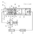
- FIG. FIG. 2 is a schematic diagram of a vehicle height adjustment device including the fluid supply device shown in FIG. 1;
- 3 is a diagram illustrating a configuration for holding an electric motor in the fluid supply device shown in FIG. 2;
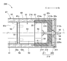
- FIG. 10 is a diagram illustrating a configuration for holding an electric motor in the fluid supply device according to the second embodiment;
- FIG. 11 is a diagram illustrating a configuration for holding an electric motor in a fluid supply device according to Example 3;
- FIG. 1 shows, for example, an off-road type two-wheeled vehicle 10 as a straddle-type vehicle.
- the two-wheeled vehicle 10 includes a vehicle body 11, an engine 12 as a power source supported at the central lower portion of the vehicle body 11, and left and right front forks 13 ( Only the right front fork 13 is shown in the drawing), the front wheel 14 sandwiched between and rotatably supported by these front forks 13, and the front wheel 14 arranged on the upper part of the front fork 13.
- the rear suspension 19 is provided with a spring 21, which is a compression coil spring that absorbs impact applied to the rear wheels from the road surface or the like.
- a spring 21 which is a compression coil spring that absorbs impact applied to the rear wheels from the road surface or the like.
- the vehicle height adjustment device 20 can control a hydraulic jack mechanism 30 that can adjust the length of the spring 21 by hydraulic pressure, a fluid supply device 40 that supplies oil (fluid) to the hydraulic jack mechanism 30, and the fluid supply device 40. and a control device 22 .
- the hydraulic jack mechanism 30 includes a support member 31 that supports the end of the spring 21 on the vehicle body side, and a storage member 32 that stores the support member 31 .
- a space including the bottom surface 32a of the storage member 32 serves as an oil chamber 33 in which oil is stored.
- the support member 31 is movable in the length direction of the spring 21 .
- the length of the hydraulic jack mechanism 30 spring 21 is adjusted by the amount of movement of the support member 31 .
- the amount of movement is, for example, the distance D between the bottom surface 32a of the storage member 32 and the opposing surface 31a of the support member 31 facing the bottom surface 32a.
- the displacement sensor 23 detects this interval D and sends a signal to the controller 22 .
- the fluid supply device 40 includes an electric motor 50 that serves as a drive source for supplying oil to the outside, a reduction gear 41 that reduces the rotational speed of the electric motor 50, and a cylinder housing the electric motor 50 and the reduction gear 41.
- a first cylinder 60 having a shape, an extrusion mechanism 70 that is driven by a speed reducer 41 to push out oil to the outside, and a second cylinder 42 that houses the extrusion mechanism 70 are provided.
- the direction in which the axis L of the electric motor 50 extends is defined as the axial direction.
- the second cylinder 42 side is the front side Fr
- the first cylinder 60 side is the rear side Rr.
- the first cylinder 60 is open at both front and rear ends.
- the second tube 42 is a bottomed tubular member in which a bottom portion 44 and a tubular portion 43 are integrally formed.
- a rear end portion 43a of the cylinder portion 43 of the second cylinder 42 is open.
- a front end portion 60 a of the first tube 60 is inserted into the rear end portion 43 a of the second tube 42 .
- the first tube 60 and the second tube 42 that are connected in the axial direction (front-to-rear direction) constitute an exterior case 47 .
- the extrusion mechanism 70 includes a rotatable shaft member 71 fixed to the output shaft 41a of the speed reducer 41, a bearing 72 rotatably supporting the shaft member 71, and an outer peripheral surface of the shaft member 71. a moving member 74 that surrounds the shaft member 71 and is pushed by the flange 73a of the nut 73 to move together with the nut 73; and a piston 75 that is fixed to the tip of the moving member 74. .
- the outer peripheral surface of the shaft member 71 has a male thread.
- the inner peripheral surface of the nut 73 has a female thread that meshes with the female thread of the shaft member 71 . Collars are attached to the inner and outer peripheral surfaces of the moving member 74, respectively.
- the bottom portion 44 of the second cylinder 42 , the cylinder portion 43 of the second cylinder 42 and the piston 75 define an oil chamber 45 .
- a hose 34 is inserted into a hole formed in the bottom portion 44 of the second cylinder 42 .
- the hose 34 communicates the oil chamber 45 of the second cylinder 42 with the oil chamber 33 of the hydraulic jack mechanism 30 .
- the first cylinder 60 has a fixing portion 60 b for fixing the speed reducer 41 to the first cylinder 60 .
- the speed reducer 41 is screwed to the fixed portion 60b using screws 48,48.
- the output shaft 41a of the speed reducer 41 passes through the fixed portion 60b.
- the speed reducer 41 and the electric motor 50 are held by the inner peripheral surface of the first cylinder 60 (radial movement of the electric motor 50 is restricted).
- the first cylinder 60 has a first inner peripheral surface 61 that is in contact with the outer peripheral surface 41b of the speed reducer 41, and is positioned behind the first inner peripheral surface 61 and has a diameter larger than the first inner peripheral surface 61. It has a large second inner peripheral surface 62 (inner peripheral surface of the exterior case) and a first stepped surface 63 connecting the first inner peripheral surface 61 and the second inner peripheral surface 62 .
- the electric motor 50 is, for example, a brushed direct current (DC) motor.
- the electric motor 50 has a case 51 that houses a coil (not shown) inside.
- the case 51 includes a contact surface 52 in contact with the rear end surface 41c of the speed reducer 41, a first outer peripheral surface 53 in contact with the first inner peripheral surface 61 of the first cylinder 60 over the entire circumference, A second outer peripheral surface 54 located behind the first outer peripheral surface 53 and having a smaller diameter than the first outer peripheral surface 53, and a second step connecting the first outer peripheral surface 53 and the second outer peripheral surface 54.
- the second stepped surface 55 of the case 51 and the first stepped surface 63 of the first tube 60 are positioned on the same plane.
- the second stepped surface 55 and the first stepped surface 63 face rearward.
- the electric motor 50 is fixed inside the first cylinder 60 by screws 58, 58 (fixing members). Each screw head 58 a is located inside the speed reducer 41 . A shaft portion 58 b of each screw extends in the axial direction and penetrates the rear end surface 41 c of the speed reducer 41 and the contact surface 52 of the electric motor 50 . The shaft portion 58b is screwed to the electric motor 50 .
- the electric motor 50 may be fixed so as to be restrained from moving in the axial direction. For example, the electric motor 50 may be fixed directly to the first cylinder 60 .
- a harness 59 for supplying electricity to the electric motor 50 is connected to the electric motor 50 .
- the harness 59 extends from the rear end surface 56 of the case 51 of the electric motor 50 to the outside of the first cylinder 60 .
- a lid body 80 is fitted to the second inner peripheral surface 62 of the first cylinder 60 .
- the lid body 80 closes the rear end portion 60c of the first cylinder 60 (the side where the harness 59 extends).
- the lid body 80 includes an inner lid 81 arranged to hold the case 51 and an outer lid 87 covering the inner lid 81 .
- Both the inner lid 81 and the outer lid 87 are made of resin.
- the inner lid 81 and the outer lid 87 are separate members from each other, but may be integrally formed.
- the inner lid 81 includes a disk-shaped main body portion 82 centered on the axis L, and a tubular holding member extending from the outer peripheral edge of the main body portion 82 to the electric motor 50 side (front side) and holding the electric motor 50 .
- the portion 84 and the portion 84 are integrally configured.
- the outer peripheral surface 82a of the body portion 82 is in contact with the second inner peripheral surface 62 of the first cylinder 60 over the entire circumference.
- the outer peripheral surface 84a of the holding portion 84 is in contact with the second inner peripheral surface 62 of the first cylinder 60 over the entire circumference.
- An inner peripheral surface 85 of the holding portion 84 is in contact with the second outer peripheral surface 54 of the electric motor 50 over the entire circumference.
- the degree of fitting between the inner peripheral surface 85 of the holding portion 84 and the second outer peripheral surface 54 of the electric motor 50 is either clearance fit (relatively rotatable) or press fit (relatively unrotatable). It's okay.
- the outer lid 87 has a disc shape centered on the axis L.
- a front end surface 87 a of the outer lid 87 overlaps a rear end surface 82 b of the body portion 82 of the inner lid 81 .
- a harness 59 of the electric motor 50 passes through the inner lid 81 and the outer lid 87 .
- a main body portion 82 of the inner lid 81 has an inner support hole 83 that supports the harness 59 passing therethrough.
- the outer lid 87 has an outer support hole 88 that supports the harness 59 passing therethrough.
- a gap between the outer support hole 88 of the outer lid 87 and the harness 59 is closed by an annular sealing member 89 .
- a second inner peripheral surface 62 of the first tube 60 is formed with a first groove 62 a along the circumferential direction of the first tube 60 .
- An annular stopper 90 is fitted in the first groove 62 a of the first tube 60 to prevent the outer lid 87 from coming off the first tube 60 .
- the diameter of the inner peripheral surface 91 of the stopper 90 is smaller than the diameter of the second inner peripheral surface 62 of the first cylinder 60 . Thereby, the stopper 90 can restrict the movement of the outer lid 87 in the axial direction.
- An end surface 86 of the holding portion 84 defines an annular space.
- An annular elastic member 93 is arranged in the annular space. The elastic member 93 is compressed in the axial direction of the electric motor 50 . Furthermore, the elastic member 93 is compressed in the radial direction of the electric motor 50 .
- the annular elastic member 93 is compressed in the radial direction of the electric motor 50 by the second outer peripheral surface 54 of the electric motor 50 and the second inner peripheral surface 62 of the first cylinder 60 . Therefore, a restoring force F ⁇ b>1 acting in the radial direction of the electric motor 50 is generated in the elastic member 93 .
- the restoring force F1 of the elastic member 93 acts on the second outer peripheral surface 54 of the electric motor 50 so as to reduce the diameter thereof.
- the electric motor 50 is held by the restoring force F1.
- the annular elastic member 93 is supported by the first stepped surface 63 of the first tube 60 , the second stepped surface 55 of the electric motor 50 , and the end surface 86 of the holding portion 84 of the inner lid 81 . compressed in the direction Therefore, a restoring force F ⁇ b>2 acting in the axial direction of the electric motor 50 is generated in the elastic member 93 .
- the restoring force F2 of the elastic member 93 acts to push the end surface 86 of the holding portion 84 of the inner lid 81 .
- the restoring force F2 prevents rotation of the inner lid 81 about the axis L. As shown in FIG.
- the restoring force F1 can prevent the electric motor 50 from rattling in the radial direction. Furthermore, the rotation of the inner lid 81 about the axis L is prevented by the restoring force F2. The durability of the fluid supply device 40 can be enhanced.
- the gap between the outer support hole 88 of the outer lid 87 and the harness 59 is closed by an annular sealing member 89 . Intrusion of dust, dirt, and liquid matter from the outside can be suppressed.
- FIG. 4 shows a fluid supply device 200 according to a second embodiment. Descriptions of configurations and effects common to the first embodiment are omitted.
- the lid body 210 includes an inner lid 211 arranged to hold the case 51 and an outer lid 220 covering the inner lid 211 .
- the inner lid 211 is made of an elastic material.
- the inner lid 211 is compressed and disposed within the first cylinder 60 .
- the inner lid 211 includes a disk-shaped body portion 212 centered on the axis L, and a tubular holding portion extending from the outer peripheral edge of the body portion 212 toward the electric motor side (front side) and holding the electric motor 50 . 214 and are configured integrally.
- the outer peripheral surface 212a of the main body portion 212 is in contact with the second inner peripheral surface 62 of the first cylinder 60 over the entire circumference.
- An outer peripheral surface 214a of the holding portion 214 is in contact with the second inner peripheral surface 62 of the first cylinder 60 over the entire circumference.
- An inner peripheral surface 215 of the holding portion 214 is in contact with the second outer peripheral surface 54 of the electric motor 50 over the entire circumference.
- the end surface 216 of the holding portion 214 is in contact with the first stepped surface 63 of the first cylinder 60 and the second stepped surface 55 of the electric motor 50 .
- the outer lid 220 has an enlarged diameter portion 221 in which a portion of the outer peripheral surface is enlarged.
- the enlarged diameter portion 221 is fitted in the first groove 62 . That is, the outer lid 220 also has the function of the annular stopper 90 that prevents the outer lid 87 from coming off from the first cylinder 60 in the first embodiment.
- the outer lid 220 is made of a flexible material. A deformed outer lid 220 can be attached to the first cylinder 60 .
- An inner peripheral surface 215 of the holding portion 214 of the inner lid 211 is in contact with the second outer peripheral surface 54 of the electric motor 50 over the entire circumference.
- An outer peripheral surface 214a of the holding portion 214 of the inner lid 211 is in contact with the second inner peripheral surface 62 of the first cylinder 60 over the entire circumference.
- the inner lid 211 is made of an elastic material.
- the holding portion 214 of the inner lid 211 is compressed in the radial direction of the electric motor 50 by the second outer peripheral surface 54 of the electric motor 50 and the second inner peripheral surface 62 of the first cylinder 60 .
- a restoring force F ⁇ b>1 acting in the radial direction of the electric motor 50 is generated in the holding portion 214 of the inner lid 211 .
- the restoring force F1 of the inner lid 211 which is an elastic member, acts on the second outer peripheral surface 54 of the electric motor 50 so as to reduce the diameter thereof.
- the electric motor 50 is held by the restoring force F1.
- the end surface 216 of the holding portion 214 of the inner lid 211 is in contact with the first stepped surface 63 of the first cylinder 60 and the second stepped surface 55 of the electric motor 50 .
- a rear end surface 212 b of the body portion 212 of the inner lid 211 is in contact with a front end surface 220 a of the outer lid 220 .
- the inner lid 211 is made of an elastic material.
- the holding portion 214 of the inner lid 211 is compressed in the axial direction of the electric motor 50 by the stepped surface of the first cylinder 60, the second stepped surface 55 of the electric motor 50, and the front end surface 220a of the outer lid 220.
- a restoring force F2 acting in the axial direction of the electric motor 50 on the first stepped surface 63 of the first cylinder 60 and the second stepped surface 55 of the electric motor 50 is generated.
- a restoring force F2 is generated on the front end surface 220a of the outer lid 220 as well.
- the restoring force F2 of the inner lid 211 which is an elastic member, can prevent the inner lid 211 from rotating.
- the restoring force F1 can prevent the electric motor 50 from rattling in the radial direction. Furthermore, the rotation of the inner lid 211 about the axis L is prevented by the restoring force F2. The durability of the fluid supply device 200 can be enhanced.
- the fluid supply device 200 of the second embodiment does not include the annular elastic member 93 (see FIG. 3) of the first embodiment. Compared with the fluid supply device 40 of the first embodiment, the number of components of the fluid supply device 200 can be reduced.
- FIG. 5 shows a fluid supply device 300 according to Example 3. As shown in FIG. Descriptions of configurations and effects common to the first embodiment are omitted.
- the first cylinder 310 has a first inner peripheral surface 311 in contact with the outer peripheral surface 41b of the speed reducer 41, and a first inner peripheral surface 311 positioned behind the first inner peripheral surface 311 and having a diameter larger than the first inner peripheral surface 311. It has a large second inner peripheral surface 312 and a first connecting surface 313 connecting the first inner peripheral surface 311 and the second inner peripheral surface 312 .
- the first connection surface 313 is inclined such that the diameter decreases from the second inner peripheral surface 312 toward the first inner peripheral surface 311 .
- An inner lid 321 of the lid body 320 includes a disc-shaped main body portion 322 centered on the axis L, and an outer peripheral edge of the main body portion 322 extending toward the electric motor 50 side (front side) to hold the electric motor 50 .
- a cylindrical holding portion 323 is integrated with the holding portion 323 .
- the holding portion 323 has a base portion 324 whose cylindrical thickness becomes thinner toward the electric motor 50 side (forward), and a thin portion 326 which is located on the front side of the base portion 324 and is thinner than the base portion 324 . ing.
- An outer peripheral surface 325 of the base portion 324 is in contact with the first connection surface 313 of the first cylinder 310 over the entire circumference.
- An outer peripheral surface 328 of the thin portion 326 is in contact with the first inner peripheral surface 311 of the first cylinder 310 over the entire circumference.
- An inner peripheral surface 327 of the thin portion 326 is in contact with the second outer peripheral surface 54 of the electric motor 50 over the entire circumference.
- a second groove 314 is formed in the first inner peripheral surface 311 of the first tube 310 in the circumferential direction of the first tube 310 .
- An annular elastic member 330 is arranged in the second groove 314 . The elastic member 330 is compressed in the radial direction of the electric motor 50 by the bottom surface of the second groove 314 and the outer peripheral surface 328 of the thin portion 326 .
- the end surface 329 of the thin portion 326 and the second stepped surface 55 of the electric motor 50 are separated from each other.
- the holding portion 323 of Example 3 has a thin portion 326 . Therefore, the thin portion 326 is easily bent so as to reduce its diameter.
- the restoring force F1 reinforces the force with which the thin portion 326 of the lid 320 holds the electric motor 50 .
- a slit extending in the axial direction of the electric motor 50 may be formed in the thin portion 326 in order to make the thin portion 326 flexible.
- the restoring force F1 can prevent the electric motor 50 from rattling in the radial direction. Furthermore, the rotation of the inner lid 321 about the axis L can also be prevented by the restoring force F1. The durability of the fluid supply device 300 can be enhanced.
- the axial restoring force of the electric motor 50 is not applied to the inner lid 321 .
- the end face 329 of the thin portion 326 is separated from the second stepped face 55 of the electric motor 50 .
- High accuracy is not required for the dimension of the inner lid 321 in the direction of the axis L, and design and manufacturing are facilitated.
- the present invention is not limited to Examples 1 to 3 as long as the actions and effects of the present invention are exhibited.
- the fluid supply device of the present invention is suitable for saddle-riding vehicles such as motorcycles and tricycles.
- Reference Signs List 40 200, 300 Fluid supply device 47, 310 Exterior case 50 Electric motor 54 Outer peripheral surface of electric motor 58 Screw (fixing member) 59... Harness 60c... End of outer case 62... Second inner peripheral surface of first cylinder (inner peripheral surface of outer case) 80, 210, 320 Lid body 84, 214, 323 Lid body holding portion 86 Lid body holding portion end surface 89 Seal member 90 Stopper 93, 330 Elastic member 211 Elastic member (lid made of elastic material) body) 328... Peripheral surface of holding portion of lid body
Landscapes
- Engineering & Computer Science (AREA)
- Mechanical Engineering (AREA)
- General Engineering & Computer Science (AREA)
- Power Engineering (AREA)
- Connection Of Motors, Electrical Generators, Mechanical Devices, And The Like (AREA)
- Details Of Reciprocating Pumps (AREA)
- Motor Or Generator Frames (AREA)
- Vehicle Body Suspensions (AREA)
Abstract
Description
図1には、鞍乗り型車両として、例えばオフロードタイプの二輪車10が示されている。二輪車10は、車体11と、この車体11の中央下部に支持された動力源であるエンジン12と、車体11の前部左右に設けられ路面の凹凸から受ける衝撃を吸収する左右のフロントフォーク13(図には、右側のフロントフォーク13のみが示されている)と、これらのフロントフォーク13によって挟まれていると共に回転可能に支持された前輪14と、フロントフォーク13の上部に配置され前輪14を操舵するハンドルパイプ15と、エンジン12の上方に設けられ乗員が着座するシート16と、車体11の後部から後方に向かって延び上下方向にスイング可能に設けられたスイングアーム17と、このスイングアーム17によって回転可能に支持された後輪18と、車体11の後部からスイングアーム17まで掛け渡された左右のリヤサスペンション19(図には、右側のリヤサスペンション19のみが示されている)と、を備えている。
流体供給装置40は、外部にオイルを供給するための駆動源となる電動モータ50と、電動モータ50の回転速度を減速させる減速機41と、電動モータ50及び減速機41を収納している筒状の第1筒60と、減速機41により駆動されてオイルを外部へ押し出す押出機構70と、押出機構70を収納している筒状の第2筒42と、を備えている。
第1筒60は、前後の両端が開いている。第2筒42は、底部44と筒部43とが一体に構成されている有底筒状の部材である。第2筒42の筒部43の後端部43aは開いている。第2筒42の後端部43aに対して、第1筒60の前端部60aが差し込まれている。軸方向(前後方向)に連結した第1筒60と第2筒42とは、外装ケース47を構成している。
押出機構70は、減速機41の出力軸41aに固定されており回転可能な軸部材71と、軸部材71を回転可能に支持しているベアリング72と、軸部材71の外周面に取り付けられているナット73と、軸部材71を囲っていると共にナット73のフランジ73aに押されてナット73と共に移動する移動部材74と、移動部材74の先端に固定されているピストン75と、を備えている。軸部材71の外周面は雄ねじを有している。ナット73の内周面は、軸部材71の雌ねじに噛み合う雌ねじを有している。移動部材74の内周面及び外周面は、それぞれカラーが取り付けられている。
制御装置22が流体供給装置40の電動モータ50を駆動させると、減速機41を介して軸部材71が回転し、ナット73が前方に移動する。ナット73が移動することにより、ナット73のフランジ73aが移動部材74を押して、移動部材74の前端に固定されたピストン75が前方に移動する。第2筒42内のオイルは、ホース34を介して、油圧ジャッキ機構30のオイル室33にオイルが供給される。オイルの圧力により支持部材31が収納部材32に底面32aから離れる方向に移動することにより、スプリング21の長さが短くなる。
第1筒60は、減速機41を第1筒60に固定するための固定部60bを有している。減速機41は、ねじ48,48を用いて固定部60bに対してねじ締結されている。減速機41の出力軸41aは、固定部60bを貫通している。
電動モータ50は、例えばブラシ付きの直流(DC)モータである。電動モータ50は、内部にコイル(不図示)を収納しているケース51を備えている。ケース51は、減速機41の後端面41cに接触している接触面52と、第1筒60の第1内周面61に対して全周に亘り接触している第1外周面53と、第1外周面53よりも後方に位置しており第1外周面53よりも径が小さい第2外周面54と、第1外周面53と第2外周面54とを接続している第2段差面55と、を有している。ケース51の第2段差面55と、第1筒60の第1段差面63と、は、同一平面上に位置している。第2段差面55と、第1段差面63とは、後方を向いている。
電動モータ50は、ねじ58,58(固定部材)により、第1筒60の内部にて固定されている。各々のねじの頭部58aは、減速機41の内部に位置している。各々のねじの軸部58bは、軸方向に延びており、減速機41の後端面41c及び電動モータ50の接触面52を貫通している。軸部58bは、電動モータ50とねじ締結している。なお、電動モータ50は、軸方向への移動を抑制できるように固定されていればよい。例えば、電動モータ50を第1筒60に対して直接に固定してもよい。
電動モータ50には、電動モータ50に電気を流すハーネス59が接続されている。ハーネス59は、電動モータ50のケース51の後端面56から第1筒60の外部へ延びている。
第1筒60の第2内周面62に対して蓋体80が嵌め込まれている。蓋体80は第1筒60の後端部60c(ハーネス59が延びている側)を塞いでいる。蓋体80は、ケース51を保持するように配置されている内蓋81と、内蓋81を覆っている外蓋87と、を備えている。内蓋81と、外蓋87とは、いずれも樹脂製である。内蓋81と、外蓋87とは、互いに別体であるが、一体に構成してもよい。
第1筒60の第2内周面62には、第1筒60の周方向に沿った第1溝62aが形成されている。第1筒60の第1溝62aには、外蓋87が第1筒60から外れることを防止する環状のストッパ90が嵌め込まれている。ストッパ90の内周面91の径は、第1筒60の第2内周面62の径よりも小さい。これにより、ストッパ90は、外蓋87の軸方向の移動を規制することができる。
第1筒60の第2内周面62と、第1筒60の第1段差面63及び電動モータ50の第2段差面55と、電動モータ50の第2外周面54と、内蓋81の保持部84の端面86とは、環状の空間を画定している。環状の空間には、環状の弾性部材93が配されている。弾性部材93は電動モータ50の軸方向に圧縮されている。さらに、弾性部材93は電動モータ50の径方向に圧縮されている。
環状の弾性部材93は、電動モータ50の第2外周面54と、第1筒60の第2内周面62とにより、電動モータ50の径方向に圧縮されている。そのため、弾性部材93には電動モータ50の径方向に作用する復元力F1が生じる。弾性部材93の復元力F1は、電動モータ50の第2外周面54に対して縮径するように作用する。復元力F1により電動モータ50が保持される。
図4には、実施例2による流体供給装置200が示されている。実施例1と共通する構成及び効果についての説明は省略する。
外蓋220の前端面220aは、内蓋211の本体部212の後端面212bに対して重ね合わされている。外蓋220は、外周面の一部が拡径されている拡径部221を有している。拡径部221は、第1溝62に嵌っている。即ち、外蓋220は、上記実施例1における、外蓋87が第1筒60から外れることを防止する環状のストッパ90の機能も有している。外蓋220は可撓性素材により構成されている。変形させた外蓋220を第1筒60に対して取付可能である。
内蓋211の保持部214の内周面215は、電動モータ50の第2外周面54に対して全周に亘り接触している。内蓋211の保持部214の外周面214aは、第1筒60の第2内周面62に対して全周に亘り接触している。内蓋211は弾性素材で構成されている。
図5には、実施例3による流体供給装置300が示されている。実施例1と共通する構成及び効果についての説明は省略する。
弾性部材330は、第2溝314の底面と、薄肉部326の外周面328とにより、電動モータ50の径方向に圧縮されている。そのため、弾性部材330には電動モータ50の径方向に作用する復元力F1が生じる。この復元力F1は、薄肉部326を縮径する方向に作用するため、薄肉部326を有する内蓋321の回転を防止することができる。
47,310…外装ケース
50…電動モータ
54…電動モータの外周面
58…ねじ(固定部材)
59…ハーネス
60c…外装ケースの端部
62…第1筒の第2内周面(外装ケースの内周面)
80,210,320…蓋体
84,214,323…蓋体の保持部
86…蓋体の保持部の端面
89…シール部材
90…ストッパ
93,330…弾性部材
211…弾性部材(弾性素材の蓋体)
328…蓋体の保持部の外周面
Claims (6)
- 外部に流体を供給するための駆動源となる電動モータと、
前記電動モータを収納している筒状の外装ケースと、
前記外装ケース内にて、前記電動モータの軸方向への前記電動モータの移動を抑制可能に、前記電動モータを固定している固定部材と、
前記電動モータに接続されており電気が流れるハーネスと、
前記外装ケースの内周面に対して嵌め込まれて前記外装ケースの端部を塞いでおり、前記電動モータから前記外装ケースの外側へ延びている前記ハーネスを支持しており、前記電動モータの外周面を全周に亘り保持している筒状の保持部を有している、蓋体と、
前記外装ケースからの前記蓋体の外れ防止をするストッパと、を備え、
前記電動モータの前記外周面と、前記外装ケースの前記内周面との間には、環状の弾性部材が圧縮されて配されており、
前記弾性部材は、前記電動モータに対して前記電動モータの径方向に復元力を作用させ、かつ、前記蓋体の前記保持部に対して復元力を作用させるように圧縮されている、流体供給装置。 - 前記電動モータの前記外周面と、前記外装ケースの前記内周面と、前記蓋体の前記保持部の端面とは、前記弾性部材を圧縮している、請求項1に記載の流体供給装置。
- 前記弾性部材は、弾性素材の前記蓋体である、請求項1に記載の流体供給装置。
- 前記蓋体の前記保持部の外周面と、前記外装ケースの前記内周面とは、弾性部材を圧縮しており、
前記弾性部材によって、前記蓋体の前記保持部は、縮径する方向の力を付与されている、請求項1に記載の流体供給装置。 - 前記ストッパは、前記蓋体と一体に構成されている、請求項1~請求項4の何れか1項に記載の流体供給装置。
- 前記ハーネスと前記蓋体との隙間を塞ぐシール部材が配されている、請求項1~請求項5の何れか1項に記載の流体供給装置。
Priority Applications (5)
| Application Number | Priority Date | Filing Date | Title |
|---|---|---|---|
| DE112021006437.1T DE112021006437T5 (de) | 2021-03-30 | 2021-03-30 | Fluidfördervorrichtung |
| JP2021517878A JP6936421B1 (ja) | 2021-03-30 | 2021-03-30 | 流体供給装置 |
| PCT/JP2021/013514 WO2022208653A1 (ja) | 2021-03-30 | 2021-03-30 | 流体供給装置 |
| GB2312310.2A GB2620031B (en) | 2021-03-30 | 2021-03-30 | Fluid supply device |
| US18/448,841 US12676531B2 (en) | 2021-03-30 | 2023-08-11 | Fluid supply device with an elastic member having high durability |
Applications Claiming Priority (1)
| Application Number | Priority Date | Filing Date | Title |
|---|---|---|---|
| PCT/JP2021/013514 WO2022208653A1 (ja) | 2021-03-30 | 2021-03-30 | 流体供給装置 |
Related Child Applications (1)
| Application Number | Title | Priority Date | Filing Date |
|---|---|---|---|
| US18/448,841 Continuation US12676531B2 (en) | 2021-03-30 | 2023-08-11 | Fluid supply device with an elastic member having high durability |
Publications (1)
| Publication Number | Publication Date |
|---|---|
| WO2022208653A1 true WO2022208653A1 (ja) | 2022-10-06 |
Family
ID=77657971
Family Applications (1)
| Application Number | Title | Priority Date | Filing Date |
|---|---|---|---|
| PCT/JP2021/013514 Ceased WO2022208653A1 (ja) | 2021-03-30 | 2021-03-30 | 流体供給装置 |
Country Status (5)
| Country | Link |
|---|---|
| US (1) | US12676531B2 (ja) |
| JP (1) | JP6936421B1 (ja) |
| DE (1) | DE112021006437T5 (ja) |
| GB (1) | GB2620031B (ja) |
| WO (1) | WO2022208653A1 (ja) |
Citations (4)
| Publication number | Priority date | Publication date | Assignee | Title |
|---|---|---|---|---|
| JPH02267093A (ja) * | 1989-04-05 | 1990-10-31 | Honda Motor Co Ltd | 減衰力可変サスペンション |
| JPH03125929U (ja) * | 1990-04-02 | 1991-12-19 | ||
| US5639228A (en) * | 1994-10-29 | 1997-06-17 | Pierburg Gmbh | Electrically driven air pump having friction-fit, air-tight seal joints |
| JP6799721B1 (ja) * | 2020-06-25 | 2020-12-16 | 株式会社ショーワ | 制御システム、鞍乗型車両 |
Family Cites Families (5)
| Publication number | Priority date | Publication date | Assignee | Title |
|---|---|---|---|---|
| US3179058A (en) * | 1963-04-10 | 1965-04-20 | Delta Electric Company | Bilge pump |
| JPS6321786U (ja) * | 1986-07-25 | 1988-02-13 | ||
| JP2010265833A (ja) * | 2009-05-15 | 2010-11-25 | Mikuni Corp | 電動ポンプ |
| EP3699450B1 (en) * | 2017-10-20 | 2026-06-10 | Astemo, Ltd. | Electric parking brake device |
| US11804751B2 (en) * | 2018-06-29 | 2023-10-31 | Ntn Corporation | Electric actuator including a holder that holds a conductive member and an elastic member that is interposed and held between the holder and a case |
-
2021
- 2021-03-30 GB GB2312310.2A patent/GB2620031B/en active Active
- 2021-03-30 WO PCT/JP2021/013514 patent/WO2022208653A1/ja not_active Ceased
- 2021-03-30 DE DE112021006437.1T patent/DE112021006437T5/de active Pending
- 2021-03-30 JP JP2021517878A patent/JP6936421B1/ja active Active
-
2023
- 2023-08-11 US US18/448,841 patent/US12676531B2/en active Active
Patent Citations (4)
| Publication number | Priority date | Publication date | Assignee | Title |
|---|---|---|---|---|
| JPH02267093A (ja) * | 1989-04-05 | 1990-10-31 | Honda Motor Co Ltd | 減衰力可変サスペンション |
| JPH03125929U (ja) * | 1990-04-02 | 1991-12-19 | ||
| US5639228A (en) * | 1994-10-29 | 1997-06-17 | Pierburg Gmbh | Electrically driven air pump having friction-fit, air-tight seal joints |
| JP6799721B1 (ja) * | 2020-06-25 | 2020-12-16 | 株式会社ショーワ | 制御システム、鞍乗型車両 |
Also Published As
| Publication number | Publication date |
|---|---|
| DE112021006437T5 (de) | 2023-11-02 |
| GB202312310D0 (en) | 2023-09-27 |
| GB2620031B (en) | 2025-02-19 |
| US20230396122A1 (en) | 2023-12-07 |
| JPWO2022208653A1 (ja) | 2022-10-06 |
| JP6936421B1 (ja) | 2021-09-15 |
| GB2620031A (en) | 2023-12-27 |
| US12676531B2 (en) | 2026-07-07 |
Similar Documents
| Publication | Publication Date | Title |
|---|---|---|
| JP3770435B2 (ja) | カバー付き筒型緩衝器 | |
| JP5029058B2 (ja) | スラスト滑り軸受及びこのスラスト滑り軸受とピストンロッドとの組合せ機構 | |
| JP2006182183A (ja) | 二輪車等のフロントフォーク装置 | |
| CN101104433A (zh) | 自行车悬挂系统 | |
| CN103192942A (zh) | 用于自行车部件的双液压控制器 | |
| JP6936421B1 (ja) | 流体供給装置 | |
| JP6464130B2 (ja) | パルサーリング取付構造 | |
| JPH0260522B2 (ja) | ||
| CN111439298A (zh) | 基于超磁致伸缩的转向机构间隙调节装置及其方法 | |
| WO2021009936A1 (ja) | 緩衝器 | |
| JP6551817B2 (ja) | タイヤ空気圧検出装置の保持構造 | |
| JP6657490B1 (ja) | 緩衝器 | |
| WO2012093712A1 (ja) | ステアリング装置 | |
| JP5311862B2 (ja) | 操舵装置 | |
| JP3266315B2 (ja) | カセット式ヘッドセット | |
| TWI910513B (zh) | 活塞組件、負板組件和空氣彈簧組件 | |
| JP3898356B2 (ja) | 二輪車のリヤフォーク取付構造 | |
| JP4940805B2 (ja) | スラスト滑り軸受及びこのスラスト滑り軸受とピストンロッドとの組合せ機構 | |
| JP7653130B2 (ja) | ラックアンドピニオン式ステアリング装置 | |
| JPH09221044A (ja) | ラックピニオン式ステアリング装置 | |
| JP2009241727A (ja) | 後輪独立操舵装置 | |
| JP2012236489A (ja) | ラック軸支持装置および車両用操舵装置 | |
| JPH10119869A (ja) | フロントフォークのホルダ固定構造 | |
| JP2024170909A (ja) | 人力駆動車用のボトムブラケットアセンブリ | |
| JP2014162345A (ja) | ギヤボックス構造 |
Legal Events
| Date | Code | Title | Description |
|---|---|---|---|
| ENP | Entry into the national phase |
Ref document number: 2021517878 Country of ref document: JP Kind code of ref document: A |
|
| 121 | Ep: the epo has been informed by wipo that ep was designated in this application |
Ref document number: 21934825 Country of ref document: EP Kind code of ref document: A1 |
|
| WWE | Wipo information: entry into national phase |
Ref document number: 112021006437 Country of ref document: DE |
|
| ENP | Entry into the national phase |
Ref document number: 202312310 Country of ref document: GB Kind code of ref document: A Free format text: PCT FILING DATE = 20210330 |
|
| WWE | Wipo information: entry into national phase |
Ref document number: 2312310.2 Country of ref document: GB |
|
| WWP | Wipo information: published in national office |
Ref document number: 2312310.2 Country of ref document: GB |
|
| 122 | Ep: pct application non-entry in european phase |
Ref document number: 21934825 Country of ref document: EP Kind code of ref document: A1 |
|
| WWG | Wipo information: grant in national office |
Ref document number: 2312310.2 Country of ref document: GB |