WO2022202855A1 - 建設機械及び建設機械用支援装置 - Google Patents
建設機械及び建設機械用支援装置 Download PDFInfo
- Publication number
- WO2022202855A1 WO2022202855A1 PCT/JP2022/013323 JP2022013323W WO2022202855A1 WO 2022202855 A1 WO2022202855 A1 WO 2022202855A1 JP 2022013323 W JP2022013323 W JP 2022013323W WO 2022202855 A1 WO2022202855 A1 WO 2022202855A1
- Authority
- WO
- WIPO (PCT)
- Prior art keywords
- data
- excavator
- operator
- image
- unit
- Prior art date
- Legal status (The legal status is an assumption and is not a legal conclusion. Google has not performed a legal analysis and makes no representation as to the accuracy of the status listed.)
- Ceased
Links
Images





Classifications
-
- G—PHYSICS
- G06—COMPUTING OR CALCULATING; COUNTING
- G06T—IMAGE DATA PROCESSING OR GENERATION, IN GENERAL
- G06T19/00—Manipulating three-dimensional [3D] models or images for computer graphics
- G06T19/20—Editing of three-dimensional [3D] images, e.g. changing shapes or colours, aligning objects or positioning parts
-
- E—FIXED CONSTRUCTIONS
- E02—HYDRAULIC ENGINEERING; FOUNDATIONS; SOIL SHIFTING
- E02F—DREDGING; SOIL-SHIFTING
- E02F9/00—Component parts of dredgers or soil-shifting machines, not restricted to one of the kinds covered by groups E02F3/00 - E02F7/00
- E02F9/26—Indicating devices
- E02F9/261—Surveying the work-site to be treated
- E02F9/262—Surveying the work-site to be treated with follow-up actions to control the work tool, e.g. controller
-
- E—FIXED CONSTRUCTIONS
- E02—HYDRAULIC ENGINEERING; FOUNDATIONS; SOIL SHIFTING
- E02F—DREDGING; SOIL-SHIFTING
- E02F3/00—Dredgers; Soil-shifting machines
- E02F3/04—Dredgers; Soil-shifting machines mechanically-driven
- E02F3/28—Dredgers; Soil-shifting machines mechanically-driven with digging tools mounted on a dipper- or bucket-arm, i.e. there is either one arm or a pair of arms, e.g. dippers, buckets
- E02F3/36—Component parts
- E02F3/42—Drives for dippers, buckets, dipper-arms or bucket-arms
- E02F3/43—Control of dipper or bucket position; Control of sequence of drive operations
-
- E—FIXED CONSTRUCTIONS
- E02—HYDRAULIC ENGINEERING; FOUNDATIONS; SOIL SHIFTING
- E02F—DREDGING; SOIL-SHIFTING
- E02F9/00—Component parts of dredgers or soil-shifting machines, not restricted to one of the kinds covered by groups E02F3/00 - E02F7/00
- E02F9/20—Drives; Control devices
- E02F9/2025—Particular purposes of control systems not otherwise provided for
-
- E—FIXED CONSTRUCTIONS
- E02—HYDRAULIC ENGINEERING; FOUNDATIONS; SOIL SHIFTING
- E02F—DREDGING; SOIL-SHIFTING
- E02F9/00—Component parts of dredgers or soil-shifting machines, not restricted to one of the kinds covered by groups E02F3/00 - E02F7/00
- E02F9/20—Drives; Control devices
- E02F9/2025—Particular purposes of control systems not otherwise provided for
- E02F9/2033—Limiting the movement of frames or implements, e.g. to avoid collision between implements and the cabin
-
- E—FIXED CONSTRUCTIONS
- E02—HYDRAULIC ENGINEERING; FOUNDATIONS; SOIL SHIFTING
- E02F—DREDGING; SOIL-SHIFTING
- E02F9/00—Component parts of dredgers or soil-shifting machines, not restricted to one of the kinds covered by groups E02F3/00 - E02F7/00
- E02F9/20—Drives; Control devices
- E02F9/2025—Particular purposes of control systems not otherwise provided for
- E02F9/205—Remotely operated machines, e.g. unmanned vehicles
-
- E—FIXED CONSTRUCTIONS
- E02—HYDRAULIC ENGINEERING; FOUNDATIONS; SOIL SHIFTING
- E02F—DREDGING; SOIL-SHIFTING
- E02F9/00—Component parts of dredgers or soil-shifting machines, not restricted to one of the kinds covered by groups E02F3/00 - E02F7/00
- E02F9/20—Drives; Control devices
- E02F9/2025—Particular purposes of control systems not otherwise provided for
- E02F9/2054—Fleet management
-
- E—FIXED CONSTRUCTIONS
- E02—HYDRAULIC ENGINEERING; FOUNDATIONS; SOIL SHIFTING
- E02F—DREDGING; SOIL-SHIFTING
- E02F9/00—Component parts of dredgers or soil-shifting machines, not restricted to one of the kinds covered by groups E02F3/00 - E02F7/00
- E02F9/26—Indicating devices
-
- E—FIXED CONSTRUCTIONS
- E02—HYDRAULIC ENGINEERING; FOUNDATIONS; SOIL SHIFTING
- E02F—DREDGING; SOIL-SHIFTING
- E02F9/00—Component parts of dredgers or soil-shifting machines, not restricted to one of the kinds covered by groups E02F3/00 - E02F7/00
- E02F9/26—Indicating devices
- E02F9/261—Surveying the work-site to be treated
-
- G—PHYSICS
- G06—COMPUTING OR CALCULATING; COUNTING
- G06F—ELECTRIC DIGITAL DATA PROCESSING
- G06F3/00—Input arrangements for transferring data to be processed into a form capable of being handled by the computer; Output arrangements for transferring data from processing unit to output unit, e.g. interface arrangements
- G06F3/01—Input arrangements or combined input and output arrangements for interaction between user and computer
- G06F3/048—Interaction techniques based on graphical user interfaces [GUI]
- G06F3/0481—Interaction techniques based on graphical user interfaces [GUI] based on specific properties of the displayed interaction object or a metaphor-based environment, e.g. interaction with desktop elements like windows or icons, or assisted by a cursor's changing behaviour or appearance
- G06F3/04817—Interaction techniques based on graphical user interfaces [GUI] based on specific properties of the displayed interaction object or a metaphor-based environment, e.g. interaction with desktop elements like windows or icons, or assisted by a cursor's changing behaviour or appearance using icons
-
- G—PHYSICS
- G06—COMPUTING OR CALCULATING; COUNTING
- G06T—IMAGE DATA PROCESSING OR GENERATION, IN GENERAL
- G06T19/00—Manipulating three-dimensional [3D] models or images for computer graphics
- G06T19/006—Mixed reality
-
- H—ELECTRICITY
- H04—ELECTRIC COMMUNICATION TECHNIQUE
- H04N—PICTORIAL COMMUNICATION, e.g. TELEVISION
- H04N13/00—Stereoscopic video systems; Multi-view video systems; Details thereof
- H04N13/20—Image signal generators
- H04N13/271—Image signal generators wherein the generated image signals comprise depth maps or disparity maps
-
- B—PERFORMING OPERATIONS; TRANSPORTING
- B60—VEHICLES IN GENERAL
- B60Y—INDEXING SCHEME RELATING TO ASPECTS CROSS-CUTTING VEHICLE TECHNOLOGY
- B60Y2200/00—Type of vehicle
- B60Y2200/40—Special vehicles
- B60Y2200/41—Construction vehicles, e.g. graders, excavators
- B60Y2200/412—Excavators
-
- E—FIXED CONSTRUCTIONS
- E02—HYDRAULIC ENGINEERING; FOUNDATIONS; SOIL SHIFTING
- E02F—DREDGING; SOIL-SHIFTING
- E02F3/00—Dredgers; Soil-shifting machines
- E02F3/04—Dredgers; Soil-shifting machines mechanically-driven
- E02F3/28—Dredgers; Soil-shifting machines mechanically-driven with digging tools mounted on a dipper- or bucket-arm, i.e. there is either one arm or a pair of arms, e.g. dippers, buckets
- E02F3/36—Component parts
- E02F3/42—Drives for dippers, buckets, dipper-arms or bucket-arms
- E02F3/43—Control of dipper or bucket position; Control of sequence of drive operations
- E02F3/435—Control of dipper or bucket position; Control of sequence of drive operations for dipper-arms, backhoes or the like
-
- G—PHYSICS
- G06—COMPUTING OR CALCULATING; COUNTING
- G06T—IMAGE DATA PROCESSING OR GENERATION, IN GENERAL
- G06T2219/00—Indexing scheme for manipulating 3D models or images for computer graphics
- G06T2219/20—Indexing scheme for editing of 3D models
- G06T2219/2004—Aligning objects, relative positioning of parts
Definitions
- the present disclosure relates to a construction machine and a construction machine support device that supports work by the construction machine.
- Patent Document 1 An excavator equipped with a display device that displays a three-dimensional CG (computer graphics) image of the excavator on three-dimensional design data is known (see Patent Document 1, for example).
- the operator of the excavator cannot determine the presence or absence of a predetermined feature around the excavator just by looking at the screen on which the CG image of the excavator is displayed on the design data. Moreover, even if the operator has grasped the arrangement position of the feature in advance, the installation position of the feature may be changed due to the convenience of the construction site or the like.
- a construction machine support device is a construction machine support device that supports excavator work, and is based on an output from a space recognition device.
- a feature data acquisition unit that acquires feature data, which is data, and a combined data generation unit that associates position information related to the construction site with data related to the position of the feature based on the feature data.
- the construction machine support device described above can more accurately grasp the arrangement of features at the construction site.
- FIG. 1 is a side view of a shovel according to an embodiment of the present disclosure
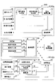
- FIG. FIG. 2 is a diagram showing a configuration of a drive control system of the excavator of FIG. 1; It is a block diagram which shows the structural example of the support apparatus for excavators. It is a figure which shows the structural example of the hydraulic system mounted in an excavator. It is a figure which shows roughly an example of a structure of an electric operation system.
- FIG. 5 is a diagram showing an example of a scene seen by an operator sitting in a driver's seat installed in a cabin of an excavator when performing slope shaping work. It is a figure which shows an example of the screen displayed on a 1st display device.
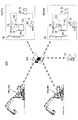
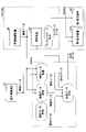
- FIG. 4 is a data flow diagram showing an example of data flow when the excavator support device displays information on the display device; 1 is a schematic diagram showing a configuration example of a support system; FIG. It is a functional block diagram which shows the structural example of a support system.
- FIG. 4 is a data flow diagram showing an example of data flow when the support system displays information on the display device; It is a figure which shows another example of the screen displayed on a 1st display device.
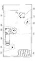
- FIG. 10 is a diagram showing another example of a screen displayed on the second display device;
- FIG. 11 is a functional block diagram showing another configuration example of the support system;
- FIG. 10 is a diagram showing still another example of a screen displayed on the second display device;
- FIG. 1 is a side view of a shovel 100 as an excavator according to an embodiment of the present disclosure.
- An upper revolving body 3 is rotatably mounted on a lower traveling body 1 of the excavator 100 through a revolving mechanism 2 .
- a boom 4 is attached to the upper swing body 3 .
- An arm 5 is attached to the tip of the boom 4, and a bucket 6 is attached to the tip of the arm 5 as an end attachment.
- the end attachment may be a slope bucket, a dredging bucket, or the like.
- the boom 4, arm 5, and bucket 6 constitute an excavation attachment, which is an example of an attachment, and are hydraulically driven by a boom cylinder 7, an arm cylinder 8, and a bucket cylinder 9, respectively.
- a boom angle sensor S1 is attached to the boom 4
- an arm angle sensor S2 is attached to the arm 5
- a bucket angle sensor S3 is attached to the bucket 6.
- the excavation attachment may be provided with a bucket tilt mechanism.
- a boom angle sensor S1 detects the rotation angle of the boom 4 .
- the boom angle sensor S1 is an acceleration sensor, and can detect the boom angle, which is the rotation angle of the boom 4 with respect to the upper rotating body 3 .
- the boom angle is, for example, the minimum angle when the boom 4 is lowered, and increases as the boom 4 is raised.
- Arm angle sensor S2 detects the rotation angle of arm 5 .
- the arm angle sensor S2 is an acceleration sensor, and can detect the arm angle, which is the rotation angle of the arm 5 with respect to the boom 4 .
- the arm angle is, for example, the minimum angle when the arm 5 is closed most, and increases as the arm 5 is opened.
- the bucket angle sensor S3 detects the rotation angle of the bucket 6.
- the bucket angle sensor S3 is an acceleration sensor and can detect the bucket angle, which is the rotation angle of the bucket 6 with respect to the arm 5 .
- the bucket angle is, for example, the smallest angle when the bucket 6 is closed most, and increases as the bucket 6 opens.
- the boom angle sensor S1, the arm angle sensor S2, and the bucket angle sensor S3 are potentiometers using variable resistors, stroke sensors that detect stroke amounts of corresponding hydraulic cylinders, or detect rotation angles around connecting pins. A rotary encoder or the like may be used.
- the boom angle sensor S1, the arm angle sensor S2, and the bucket angle sensor S3 constitute a posture sensor that detects the posture of the excavation attachment.
- the fuselage tilt sensor S4 is configured to detect the tilt of the upper revolving structure 3 with respect to a predetermined plane.
- the fuselage tilt sensor S4 is an acceleration sensor that detects the tilt angle about the longitudinal axis and the tilt angle about the lateral axis of the upper swing structure 3 with respect to the horizontal plane.
- the longitudinal axis and the lateral axis of the upper swing body 3 are orthogonal to each other and pass through a shovel center point, which is one point on the swing axis of the shovel 100 .
- the turning angular velocity sensor S5 is configured to detect the turning angular velocity of the upper turning body 3.
- the turning angular velocity sensor S5 is a gyro sensor.
- the turning angular velocity sensor S5 may be a resolver, a rotary encoder, or the like.
- the turning angular velocity sensor S5 may detect turning velocity.
- the turning speed may be calculated from the turning angular velocity.
- the space recognition device S6 is configured to recognize the state of the space around the shovel 100.
- the space recognition device S6 includes a rear space recognition device attached to the rear end of the upper surface of the upper revolving body 3, a left space recognition device attached to the left end of the upper surface of the upper revolving body 3, and a right end of the upper surface of the upper revolving body 3. At least one of a right space recognition device attached to the cabin 10 and a front space recognition device attached to the front end of the upper surface of the cabin 10 may be used.
- the spatial recognition device S6 is a camera.
- the space recognition device S6 may be a LIDAR, an ultrasonic sensor, a millimeter wave radar, an infrared sensor, a stereo camera, or the like.
- the space recognition device S6 includes a rear space recognition device, a front space recognition device, a left space recognition device, and a right space recognition device. Only the rear space recognition device is illustrated, and illustration of the front space recognition device, the left space recognition device, and the right space recognition device is omitted.
- the space recognition device S6 may be configured to detect a predetermined object within a predetermined area set around the shovel 100.
- the space recognition device S6 may have a human detection function configured to detect a person while distinguishing between a person and an object other than a person.
- the communication device S7 is a device that controls communication between the excavator 100 and the outside.
- the communication device S7 controls wireless communication between an external GNSS (Global Navigation Satellite System) survey system and the excavator 100, for example.
- the excavator 100 can acquire the design data via wireless communication by using the communication device S7.
- the excavator 100 may acquire the design data using a semiconductor memory or the like.
- the design data includes three-dimensional design data.
- the positioning device S8 is configured to acquire information about the position of the excavator 100.
- the positioning device S8 is configured to measure the position and orientation of the excavator 100 .
- the positioning device S8 is a GNSS receiver incorporating an electronic compass, which measures the latitude, longitude, and altitude of the current position of the excavator 100 and also measures the orientation of the excavator 100 .
- An input device D1, a sound output device D2, a first display device D3, a second display device D3S, a storage device D4, a gate lock lever D5, a controller 30, and an excavator support device 50 are installed in the cabin 10.
- the controller 30 functions as a main control unit that controls the drive of the excavator 100 .
- the controller 30 is configured by an arithmetic processing unit including a CPU, an internal memory, and the like.
- Various functions of the controller 30 are implemented by the CPU executing programs stored in the internal memory.
- the excavator support device 50 is an example of a construction machine support device, and is configured to support the work performed by the excavator 100 .
- the excavator support device 50 is configured, for example, to visually and audibly notify the operator of the vertical distance between the target construction surface and the work site of the bucket 6 .
- the target construction surface is a portion of the construction data derived from the design data.
- the excavator support device 50 can guide the operation of the excavator 100 by the operator.
- the excavator support device 50 may only visually notify the operator of the distance, or may only audibly notify the operator of the distance.
- the excavator support device 50 is composed of an arithmetic processing device including a CPU, an internal memory, and the like. Various functions of the excavator support device 50 are realized by the CPU executing a program stored in the internal memory.
- the excavator support device 50 may be integrated with the controller 30 .
- the input device D ⁇ b>1 is a device for the operator of the excavator 100 to input various information to the excavator support device 50 .
- the input device D1 is a membrane switch attached around the first display device D3.
- the input device D1 may be individually installed in association with each of the first display device D3 and the second display device D3S.
- the input device D1 may be a touch panel.
- the sound output device D2 outputs various audio information in response to a sound output command from the excavator support device 50.
- the sound output device D2 is an in-vehicle speaker directly connected to the excavator support device 50 .
- the sound output device D2 may be an alarm such as a buzzer.
- the first display device D3 and the second display device D3S output various image information according to commands from the excavator support device 50.
- the first display device D3 and the second display device D3S are in-vehicle liquid crystal displays that are directly connected to the excavator support device 50 .
- a camera image captured by the camera as the space recognition device S6 is displayed on the first display device D3.
- a camera image may be displayed on the second display device D3S.
- the screen size of the second display device D3S is larger than the screen size of the first display device D3.
- the screen size of the second display device D3S may be smaller than the screen size of the first display device D3.
- the storage device D4 is a device for storing various information.
- a nonvolatile storage medium such as a semiconductor memory is used as the storage device D4.
- the storage device D4 stores design data and the like.
- the storage device D4 may store various types of information output by the excavator support device 50 and the like.
- the gate lock lever D5 is a mechanism that prevents the excavator 100 from being operated by mistake.
- the gate lock lever D5 is arranged between the door of the cabin 10 and the driver's seat 10S.
- various operation devices become operable.
- the gate lock lever D5 is pushed down, various operation devices are disabled.
- FIG. 2 is a diagram showing a configuration example of the drive control system of the excavator 100 of FIG.
- the mechanical power transmission system is indicated by a double line
- the hydraulic oil line is indicated by a thick solid line
- the pilot line is indicated by a broken line
- the electric drive/control system is indicated by a thin solid line.
- the engine 11 is the power source of the shovel 100.
- the engine 11 is a diesel engine that employs isochronous control that keeps the engine speed constant regardless of changes in engine load.
- Fuel injection amount, fuel injection timing, boost pressure, etc. in the engine 11 are controlled by an engine controller unit (ECU) D7.
- ECU engine controller unit
- the rotating shaft of the engine 11 is connected to the rotating shafts of the main pump 14 and the pilot pump 15 as hydraulic pumps.
- a control valve unit 17 is connected to the main pump 14 via a hydraulic oil line.
- the control valve unit 17 is a hydraulic control device that controls the hydraulic system of the excavator 100 .
- Hydraulic actuators such as the left and right traveling hydraulic motors, the boom cylinder 7, the arm cylinder 8, the bucket cylinder 9, and the turning hydraulic motor are connected to the control valve unit 17 via hydraulic oil lines.
- the turning hydraulic motor may be a turning motor generator.
- An operating device 26 is connected to the pilot pump 15 via a pilot line.
- the operating device 26 includes levers and pedals.
- the operating device 26 is connected to the control valve unit 17 via a hydraulic line and a gate lock valve D6.
- the gate lock valve D6 switches between communication and disconnection of the hydraulic line that connects the control valve unit 17 and the operating device 26.
- the gate lock valve D ⁇ b>6 is an electromagnetic valve that switches between communication and disconnection of the hydraulic line according to a command from the controller 30 .
- the controller 30 determines the state of the gate lock lever D5 based on the state signal output by the gate lock lever D5. When the controller 30 determines that the gate lock lever D5 is pulled up, it outputs a communication command to the gate lock valve D6. When the communication command is received, the gate lock valve D6 opens to connect the hydraulic lines. As a result, the operator's operation on the operating device 26 becomes effective.
- the controller 30 determines that the gate lock lever D5 is pulled down, it outputs a shutoff command to the gate lock valve D6.
- the gate lock valve D6 closes to shut off the hydraulic line. As a result, the operator's operation on the operating device 26 becomes invalid.
- the operation sensor 29 detects the operation content of the operation device 26.
- the operation sensor 29 is a pressure sensor and outputs a detected value to the controller 30 .
- the operation sensor 29 may be another sensor such as an angle sensor or a resistance sensor.
- FIG. 2 shows the connection relationship between the controller 30 and the first display device D3 and the second display device D3S.
- the first display device D3 and the second display device D3S are connected to the controller 30 via the excavator support device 50 .
- the first display device D3, the second display device D3S, the excavator support device 50, and the controller 30 may be connected via a communication network such as CAN.
- the first display device D3 includes a conversion processing unit D3a that generates an image.
- the conversion processing unit D3a generates a camera image for display based on the output of the camera as the space recognition device S6.
- the space recognition device S6 is connected to the first display device D3 via, for example, a dedicated line.
- the conversion processing unit D3a generates an image for display based on the output of the controller 30 or the excavator support device 50.
- the conversion processing unit D3a converts various types of information output by the controller 30 or the excavator support device 50 into image signals.
- the information output by the controller 30 includes, for example, data indicating the temperature of engine cooling water, data indicating the temperature of hydraulic oil, data indicating the remaining amount of fuel, data indicating the remaining amount of urea water, and the like.
- the information output by the excavator support device 50 includes data indicating the position of the work portion of the bucket 6, data indicating the orientation of the slope to be worked, data indicating the orientation of the excavator 100, and information indicating whether the excavator 100 faces the slope. It includes data indicating the operation direction for
- the second display device D3S like the first display device D3, includes a conversion processing section D3Sa that generates an image.
- the second display device D3S is not directly connected to the spatial recognition device S6. Therefore, the conversion processing unit D3Sa does not generate a camera image. However, the conversion processing unit D3Sa may generate a camera image when the second display device D3S is directly connected to the space recognition device S6.
- the conversion processing unit D3Sa generates an image for display based on the output of the excavator support device 50.
- the conversion processing unit D3Sa converts various information output by the excavator support device 50 into an image signal.
- an image for display may be generated based on the output of the controller 30 .
- the conversion processing unit D3a may be realized as a function of the controller 30 or the excavator support device 50, not as a function of the first display device D3.
- the space recognition device S6 is connected to the controller 30 or the excavator support device 50 instead of the first display device D3.
- the first display device D3 and the second display device D3S operate by being supplied with power from the storage battery 70.
- the storage battery 70 is charged with electric power generated by the alternator 11 a (generator) of the engine 11 .
- the electric power of the storage battery 70 is supplied to the electrical components 72 of the excavator 100 and the like in addition to the controller 30, the first display device D3, and the second display device D3S.
- a starter 11 b of the engine 11 is driven by electric power from the storage battery 70 to start the engine 11 .
- the engine 11 is controlled by an engine controller unit D7.
- Various data indicating the state of the engine 11 are constantly transmitted to the controller 30 from the engine controller unit D7.
- Various data indicating the state of the engine 11 is an example of operation information of the excavator 100, and includes, for example, data indicating the cooling water temperature detected by the water temperature sensor 11c as an operation information acquisition unit.
- the controller 30 can store this data in a temporary storage unit (memory) 30a and transmit it to the first display device D3 when necessary.
- Various data are supplied to the controller 30 as operation information of the excavator 100 as described below, and are stored in the temporary storage section 30a of the controller 30.
- data indicating the tilt angle of the swash plate is supplied to the controller 30 from the regulator 13 of the main pump 14, which is a variable displacement hydraulic pump. Further, data indicating the discharge pressure of the main pump 14 is supplied to the controller 30 from the discharge pressure sensor 14b. These data are stored in the temporary storage unit 30a. Further, an oil temperature sensor 14c is provided in a pipe line between the main pump 14 and a tank in which the hydraulic oil sucked by the main pump 14 is stored, and data representing the temperature of the hydraulic oil flowing through the pipe line is provided. It is supplied to the controller 30 from the oil temperature sensor 14c.
- the regulator 13, the discharge pressure sensor 14b, and the oil temperature sensor 14c are examples of the operation information acquisition section.
- Data indicating the amount of stored fuel is supplied to the controller 30 from the stored fuel amount detection unit 55 a in the fuel storage unit 55 .
- data indicating the remaining amount of fuel is supplied to the controller 30 from a remaining fuel sensor as the stored fuel amount detection unit 55 a in the fuel tank as the fuel storage unit 55 .
- the remaining fuel sensor consists of a float that follows the liquid level and a variable resistor (potentiometer) that converts the amount of vertical fluctuation of the float into a resistance value.
- the fuel remaining amount sensor can steplessly display the remaining amount of fuel on the first display device D3.
- the detection method of the contained fuel amount detection unit can be appropriately selected according to the usage environment and the like, and a detection method that can display the state of the remaining amount of fuel in stages may be employed. These configurations are the same for the urea water tank.
- the operation sensor 29 detects the pilot pressure acting on the control valve unit 17 when the operation device 26 is operated, and data indicating the detected pilot pressure is supplied to the controller 30 .
- the excavator 100 has an engine speed adjustment dial 75 inside the cabin 10 .
- the engine rotation speed adjustment dial 75 is a dial for adjusting the rotation speed of the engine 11, and allows the engine rotation speed to be switched in four stages. Data indicating the set state of the engine speed is transmitted from the engine speed adjustment dial 75 to the controller 30 .
- the engine speed adjustment dial 75 allows the engine speed to be switched in four stages of SP mode, H mode, A mode, and IDLE mode.
- FIG. 2 shows a state in which the engine speed adjustment dial 75 is used to select the H mode.
- the SP mode is a rotation speed mode that is selected when you want to give priority to the amount of work, and uses the highest engine speed.
- the H mode is a rotational speed mode that is selected when it is desired to achieve both work load and fuel efficiency, and utilizes the second highest engine rotational speed.
- the A mode is a rotational speed mode selected when it is desired to operate the excavator 100 with low noise while giving priority to fuel efficiency, and uses the third highest engine rotational speed.
- the IDLE mode is a rotational speed mode selected when the engine 11 is to be in an idling state, and utilizes the lowest engine rotational speed. Then, the engine speed of the engine 11 is controlled to be constant at the engine speed in the speed mode set by the engine speed adjustment dial 75 .
- FIG. 3 is a functional block diagram showing a configuration example of the excavator support device 50. As shown in FIG. 3
- the excavator support device 50 includes a boom angle sensor S1, an arm angle sensor S2, a bucket angle sensor S3, a body tilt sensor S4, a turning angular velocity sensor S5, an input device D1, a communication device S7, a positioning device S8, a controller 30, and the like. receive information; Various calculations are executed based on the received information and the information stored in the storage device D4, and the calculation results are output to the sound output device D2, the first display device D3, the second display device D3S, and the like.
- the excavator support device 50 calculates the height of the work part of the attachment, and outputs a control command according to the distance between the height of the work part and a predetermined target height to the sound output device D2 and the first display. Output to at least one of the devices D3.
- the sound output device D2 that has received the control command outputs a sound representing the magnitude of the distance.
- the first display device D3 that has received the control command displays an image representing the magnitude of the distance.
- the target height is a concept that includes a target depth. This is the height that is automatically calculated from the orientation.
- the excavator support device 50 includes functional elements such as an inclination angle calculation unit 501, a height calculation unit 502, a distance calculation unit 503, and an operation direction display unit 504 in order to perform the guidance described above. Further, the excavator support device 50 includes a design data acquisition unit 505, a feature data acquisition unit 506, a synthetic data generation unit 507, a contact avoidance control unit 508, an object It includes functional elements such as a data acquisition unit 509 and a display control unit 510 . These functional elements may be implemented in software, hardware, or a combination of software and hardware. The same applies to other functional elements described later.
- the tilt angle calculator 501 calculates the tilt angle of the excavator 100, which is the tilt angle of the upper revolving structure 3 with respect to the horizontal plane, based on the detection signal from the machine body tilt sensor S4. That is, the tilt angle calculator 501 calculates the tilt angle of the excavator 100 using the detection signal from the machine body tilt sensor S4.
- the height calculator 502 calculates the tilt angle calculated by the tilt angle calculator 501 and the boom 4, arm 5, and bucket calculated from detection signals of the boom angle sensor S1, the arm angle sensor S2, and the bucket angle sensor S3. 6, and the height of the working portion of the attachment with respect to the reference plane is calculated.
- the tip (toe) of the bucket 6 corresponds to the working portion of the attachment.
- the back surface of the bucket 6 is used for leveling earth and sand, the back surface of the bucket 6 corresponds to the working portion of the attachment.
- a breaker is used as an end attachment other than the bucket 6, the tip of the breaker corresponds to the working portion of the attachment.
- the reference plane is, for example, a horizontal plane on which the shovel 100 is positioned.
- the distance calculation unit 503 calculates the distance between the height of the work site calculated by the height calculation unit 502 and the target height. When excavating with the tip of the bucket 6, the distance calculation unit 503 calculates the distance between the tip (toe) height of the bucket 6 calculated by the height calculation unit 502 and the target height. When the back surface of the bucket 6 is used for smoothing earth and sand, the distance calculation unit 503 calculates the distance between the height of the back surface of the bucket 6 calculated by the height calculation unit 502 and the target height.
- the operation direction display unit 504 is a functional element that displays on the output image an image representing the operation direction for making the shovel 100 face the slope as the work target.
- the operation direction display unit 504 automatically derives the direction in which the excavator 100 faces the slope from the design data, and superimposes an arrow indicating the direction of operation for causing the excavator 100 to face the slope on the terrain image. do.
- the terrain image includes, for example, a target terrain image that is a three-dimensional CG image of the target construction surface.
- the operation direction display unit 504 may display an image representing the operation direction for making the excavator 100 face the slope in a portion other than the portion where the terrain image is displayed.
- the image representing the operation direction may be an image representing the turning direction or an image representing the traveling direction.
- the design data acquisition unit 505 is configured to acquire three-dimensional design data.
- the design data acquisition unit 505 is configured to acquire three-dimensional design data through the communication device S7.
- the design data acquisition unit 505 is configured to store the acquired three-dimensional design data in the storage device D4.
- Three-dimensional design data is expressed, for example, in a reference coordinate system.
- the reference coordinate system is, for example, the world geodetic system.
- the world geodetic system is a three-dimensional orthogonal system with the origin at the center of gravity of the earth, the X axis in the direction of the intersection of the Greenwich meridian and the equator, the Y axis in the direction of 90 degrees east longitude, and the Z axis in the direction of the North Pole. It is an XYZ coordinate system.
- the feature data acquisition unit 506 is configured to acquire feature data, which is data relating to the range (position) where a predetermined feature exists around the excavator 100 .
- the feature data acquisition unit 506 recognizes the presence of a predetermined feature by applying image recognition processing to the camera image captured by the camera as the space recognition device S6.
- Image recognition processing is, for example, pattern matching processing, processing using machine learning (learning models such as deep learning), processing using pattern recognition models such as support vector machines, or processing using SIFT features.
- the feature data acquisition unit 506 Based on the output of the positioning device S8, the feature data acquisition unit 506 identifies the range in which the image-recognized predetermined feature exists.
- a range in which a predetermined feature exists is specified, for example, by coordinates (latitude, longitude, and altitude) of a virtual three-dimensional figure surrounding the range.
- a virtual three-dimensional figure is, for example, a sphere, a rectangular parallelepiped, a cylinder, a prism, a cone, a quadrangular pyramid, or the like.
- the coordinates relating to the virtual three-dimensional figure are, for example, the coordinates of the vertex or center point of the virtual three-dimensional figure.
- a predetermined feature is a feature that the operator of the excavator 100 should pay attention to when performing work using the excavator 100.
- a finished shape portion that is a portion where construction has been completed, or a target for slope shaping work.
- They are a handrail installed on the shoulder TS of the slope, a simple staircase, a wall, an electric wire, a road cone, a building, etc. installed on the slope that is the target of the slope shaping work.
- the ready-formed portion is a slope portion for which slope shaping work has been completed, a ground surface portion for which leveling work has been completed, or an excavated portion for which excavation work has been completed.
- the features that should be paid attention to are information registered in the feature data acquisition unit 506 in advance.
- the feature data acquisition unit 506 extracts a place to pay attention to from the output data of the space recognition device S6 based on the output data output from the space recognition device S6 and information registered in advance as a feature to pay attention to.
- the presence or absence of an object and its type, position, or time of existence are determined and stored.
- the pre-registered information is electric wires and road cones
- the feature data acquisition unit 506 uses the output data of the space recognition device S6 and the pre-registered information to Determine if a wire or road cone is present.
- the feature data acquisition unit 506 determines that a road cone exists at the construction site, it records the position and time of the road cone.
- the feature data acquisition unit 506 acquires the construction information based on the information about the work of the excavator 100 in the past. stores the position and time of the completed part.
- the information about the work includes information about the content of the work determined based on the output from the posture sensor of the excavator and the position where the work was performed.
- the camera image may be an image output by a space recognition device (for example, a camera, etc.) installed outside the excavator 100 .
- the space recognition device installed outside the excavator 100 may be, for example, a space recognition device (such as a camera or LIDAR) mounted on a flying object such as a drone, or may be a space recognition device mounted on a steel tower or the like in a construction site. It may be a camera, or it may be a camera attached to another excavator operating within the same construction site.
- the feature data may be updated at a predetermined timing.
- the feature data acquisition unit 506 may be configured to acquire feature data from a device outside the excavator 100 at predetermined time intervals.
- Devices external to the excavator 100 are, for example, excavator support devices mounted on other excavators operating within the same construction site.
- the excavator 100 can share feature data between the excavator 100 and another excavator. Even if another excavator does not have a space recognition device, the operator of the other excavator can grasp the positional relationship between the feature and the target construction surface at the construction site.
- the feature data acquisition unit 506 may be provided in a management device connected to the excavator 100 via a communication network.
- the synthetic data generation unit 507 is configured to generate synthetic data by synthesizing the design data indicating the position information related to the construction site and the feature data.
- the combined data generation unit 507 is configured to generate combined data by combining the design data acquired by the design data acquisition unit 505 and the feature data acquired by the feature data acquisition unit 506. ing.
- the combined data generation unit 507 integrates the feature data, which is information about the range (position) where the predetermined feature specified by the feature data acquisition unit 506 exists, as a part of the design data. An example in which three-dimensional design data is used as design data will be described below.
- the combined data generation unit 507 may be configured to generate combined data by combining terrain data and feature data indicating position information related to the construction site.
- the terrain data is acquired by recognizing the construction site with a space recognition device installed outside the excavator 100 .
- topography data of a construction site is acquired by a space recognition device (for example, camera, LIDAR, etc.) mounted on a flying object such as a drone.
- the synthetic data generation unit 507 associates and stores the position information (design data or terrain data) related to the construction site and the data related to the position of the feature contained in the feature data.
- the contact avoidance control unit 508 is configured to execute control to avoid contact between a predetermined feature and the excavator 100 based on the combined data.
- the contact avoidance control unit 508 utilizes the information on the position and orientation of the excavator 100 output by the positioning device S8 and the synthesized data, which is three-dimensional design data in which feature data is integrated, to control the excavator 100. and a given feature. Then, the contact avoidance control section 508 outputs a contact avoidance command to the controller 30 when it determines that the distance is less than the predetermined distance.
- the controller 30 that has received the contact avoidance command suppresses or stops the movement of the excavator 100 . For example, the controller 30 stops movement of the hydraulic actuator by outputting a shutoff command to the gate lock valve D6.
- the object data acquisition unit 509 is configured to acquire object data, which is data relating to the positions of objects around the excavator 100 .
- object data is data relating to the positions of objects around the excavator 100 .
- the object data acquisition unit 509 acquires data regarding the position of the object. is acquired as object data.
- Object data may be limited to, for example, data relating to objects having a height equal to or greater than a predetermined height.
- the object data acquisition unit 509 determines that the height of the object is less than the predetermined height. It may be configured not to acquire the data regarding the position of the object as the object data when it is determined that the object is.
- Object data is represented, for example, by coordinates (latitude, longitude, and altitude) in a reference coordinate system.
- the object data acquisition unit 509 calculates the distance between the object and the shovel 100, for example, based on the camera image captured by the camera as the space recognition device S6.
- the object data acquisition unit 509 may, for example, calculate the distance between the object and the shovel 100 based on the distance data acquired by the LIDAR as the space recognition device S6.
- the combined data generation unit 507 may combine the object data with the three-dimensional design data or terrain data.
- the synthetic data generation unit 507 may integrate the object data acquired by the object data acquisition unit 509 as part of the three-dimensional design data or terrain data.
- the contact avoidance control unit 508 may perform control to avoid contact between the object and the excavator 100 based on the three-dimensional design data in which the object data is integrated.
- the contact avoidance control unit 508 may perform control to avoid contact between the object and the shovel 100 based on the terrain data in which the object data is integrated.
- the display control unit 510 is configured to display the synthesized data on the display device.
- the display control unit 510 is configured to display the synthesized data on the second display device D3S.
- the display control unit 510 displays a pre-registered icon at the position of a predetermined feature in the virtual space represented by the three-dimensional design data or terrain data.
- the position of the predetermined feature is, for example, the coordinates of the center of the range in which the predetermined feature specified by the feature data acquisition unit 506 exists.
- the pre-registered icon is, for example, an illustration image representing the predetermined feature, and may include text information.
- the display control unit 510 may display a model of a predetermined feature at the position of the predetermined feature in the virtual space represented by the design data or terrain data.
- the model of the predetermined feature may be, for example, a three-dimensional model (three-dimensional polygon model or the like) generated based on a camera image taken by a camera as the space recognition device S6.
- the display control unit 510 may be configured to display a mark such as "X" or "O" at the position indicated by the object data.
- the display control unit 510 may be configured to display a mark at the position of the object data acquired by the object data acquiring unit 509 in the virtual space represented by the three-dimensional design data or terrain data.
- FIG. 4 shows a configuration example of a hydraulic system mounted on the excavator 100 of FIG.
- FIG. 4 shows mechanical power transmission lines, hydraulic fluid lines, pilot lines, and electrical control lines in double, solid, dashed, and dotted lines, respectively.
- the hydraulic system circulates hydraulic oil from a left main pump 14L driven by the engine 11 to a hydraulic oil tank through a left center bypass pipe 40L or a left parallel pipe 42L, and a right main pump 14L driven by the engine 11. Hydraulic oil is circulated from the pump 14R to the hydraulic oil tank through the right center bypass line 40R or the right parallel line 42R.
- the left center bypass line 40L is a hydraulic oil line passing through the control valves 171, 173, 175L and 176L arranged inside the control valve unit 17.
- the right center bypass line 40R is a hydraulic oil line passing through control valves 172, 174, 175R and 176R arranged in the control valve unit 17.
- the control valve 171 supplies the hydraulic fluid discharged from the left main pump 14L to the left traveling hydraulic motor 1L and discharges the hydraulic fluid discharged from the left traveling hydraulic motor 1L to the hydraulic fluid tank. It is a spool valve that switches the flow.
- the control valve 172 supplies the hydraulic fluid discharged from the right main pump 14R to the right traveling hydraulic motor 1R and discharges the hydraulic fluid discharged from the right traveling hydraulic motor 1R to the hydraulic fluid tank. It is a spool valve that switches the flow.
- the control valve 173 supplies hydraulic fluid discharged by the left main pump 14L to the turning hydraulic motor 2A, and controls the flow of hydraulic fluid in order to discharge the hydraulic fluid discharged by the turning hydraulic motor 2A to the hydraulic fluid tank. It is a switching spool valve.
- the control valve 174 is a spool valve that switches the flow of hydraulic oil to supply the hydraulic oil discharged by the right main pump 14R to the bucket cylinder 9 and to discharge the hydraulic oil in the bucket cylinder 9 to the hydraulic oil tank. .
- the control valve 175L is a spool valve that switches the flow of hydraulic oil in order to supply the hydraulic oil discharged by the left main pump 14L to the boom cylinder 7.
- the control valve 175R is a spool valve that switches the flow of hydraulic oil to supply the hydraulic oil discharged from the right main pump 14R to the boom cylinder 7 and to discharge the hydraulic oil in the boom cylinder 7 to the hydraulic oil tank. .
- the control valve 176L is a spool valve that switches the flow of hydraulic fluid to supply the hydraulic fluid discharged by the left main pump 14L to the arm cylinder 8 and to discharge the hydraulic fluid in the arm cylinder 8 to the hydraulic fluid tank. .
- the control valve 176R is a spool valve that switches the flow of hydraulic fluid to supply the hydraulic fluid discharged from the right main pump 14R to the arm cylinder 8 and to discharge the hydraulic fluid in the arm cylinder 8 to the hydraulic fluid tank. .
- the left parallel pipeline 42L is a hydraulic oil line parallel to the left center bypass pipeline 40L.
- the left parallel pipeline 42L can supply hydraulic fluid to more downstream control valves when the flow of hydraulic fluid through the left center bypass pipeline 40L is restricted or blocked by any of the control valves 171, 173, 175L.
- the right parallel pipeline 42R is a hydraulic oil line parallel to the right center bypass pipeline 40R.
- the right parallel line 42R can supply hydraulic fluid to more downstream control valves when the flow of hydraulic fluid through the right center bypass line 40R is restricted or blocked by any of the control valves 172, 174, 175R. .
- the left regulator 13L is configured to be able to control the discharge amount of the left main pump 14L.
- the left regulator 13L controls the discharge amount of the left main pump 14L, for example, by adjusting the tilt angle of the swash plate of the left main pump 14L according to the discharge pressure of the left main pump 14L.
- the right regulator 13R is configured to be able to control the discharge amount of the right main pump 14R.
- the right regulator 13R controls the discharge amount of the right main pump 14R, for example, by adjusting the swash plate tilt angle of the right main pump 14R according to the discharge pressure of the right main pump 14R.
- the left regulator 13L for example, adjusts the tilt angle of the swash plate of the left main pump 14L according to an increase in the discharge pressure of the left main pump 14L to reduce the discharge amount.
- the pump absorption horsepower which is represented by the product of the discharge pressure and the discharge amount, does not exceed the output horsepower of the engine 11 .
- the pump absorption horsepower is the sum of the absorption horsepower of the left main pump 14L and the absorption horsepower of the right main pump 14R.
- the left discharge pressure sensor 28L is an example of the discharge pressure sensor 28, detects the discharge pressure of the left main pump 14L, and outputs the detected value to the controller 30. The same applies to the right discharge pressure sensor 28R.
- a left throttle 18L is arranged between the most downstream control valve 176L and the hydraulic oil tank in the left center bypass pipe 40L.
- the flow of hydraulic oil discharged from the left main pump 14L is restricted by the left throttle 18L.
- the left throttle 18L generates a control pressure for controlling the left regulator 13L.
- the left control pressure sensor 19L is a sensor for detecting control pressure, and outputs the detected value to the controller 30 .
- a right throttle 18R is disposed between the most downstream control valve 176R and the hydraulic fluid tank in the right center bypass line 40R.
- the flow of hydraulic oil discharged from the right main pump 14R is restricted by the right throttle 18R.
- the right throttle 18R generates a control pressure for controlling the right regulator 13R.
- the right control pressure sensor 19 ⁇ /b>R is a sensor for detecting control pressure, and outputs the detected value to the controller 30 .
- the controller 30 controls the discharge amount of the left main pump 14L by adjusting the tilt angle of the swash plate of the left main pump 14L according to the control pressure.
- the controller 30 decreases the discharge amount of the left main pump 14L as the control pressure increases, and increases the discharge amount of the left main pump 14L as the control pressure decreases.
- the discharge amount of the right main pump 14R is similarly controlled.
- the hydraulic oil discharged by the left main pump 14L flows through the left center bypass pipe 40L. It reaches the left diaphragm 18L.
- the flow of hydraulic fluid discharged from the left main pump 14L increases the control pressure generated upstream of the left throttle 18L.
- the controller 30 reduces the discharge amount of the left main pump 14L to the minimum allowable discharge amount, thereby suppressing pressure loss (pumping loss) when the discharged hydraulic oil passes through the left center bypass pipe 40L.
- hydraulic fluid discharged from the left main pump 14L flows into the operated hydraulic actuator via the control valve corresponding to the operated hydraulic actuator. Then, the flow of hydraulic oil discharged from the left main pump 14L reduces or eliminates the amount reaching the left throttle 18L, thereby reducing the control pressure generated upstream of the left throttle 18L. As a result, the controller 30 increases the discharge amount of the left main pump 14L, circulates a sufficient amount of working oil to the hydraulic actuator to be operated, and ensures the driving of the hydraulic actuator to be operated. The same applies to the hydraulic oil discharged by the right main pump 14R.
- the hydraulic system of FIG. 4 can suppress wasteful energy consumption in each of the left main pump 14L and the right main pump 14R in the standby state. Wasteful energy consumption is caused by the pumping loss caused by the hydraulic oil discharged by the left main pump 14L in the left center bypass pipe 40L, and the pumping loss caused by the hydraulic oil discharged by the right main pump 14R in the right center bypass pipe 40R. Including Ross. Further, in the hydraulic system of FIG. 4, when the hydraulic actuators are to be operated, necessary and sufficient hydraulic fluid can be supplied from the left main pump 14L and the right main pump 14R to the hydraulic actuators to be operated.
- the boom operating lever 26A is an example of an electric operating lever as the operating device 26 and is used to operate the boom 4. As shown in FIG.
- the boom control lever 26A detects an operation direction and an operation amount, and outputs the detected operation direction and operation amount to the controller 30 as operation data (electrical signal).
- the controller 30 controls the opening of the proportional valve 31AL according to the amount of operation of the boom operating lever 26A.
- the hydraulic oil discharged by the pilot pump 15 is used to apply a pilot pressure corresponding to the amount of operation of the boom control lever 26A to the right pilot port of the control valve 175L and the left pilot port of the control valve 175R.
- the controller 30 controls the opening of the proportional valve 31AR according to the amount of operation of the boom operating lever 26A.
- the hydraulic oil discharged by the pilot pump 15 is used to apply a pilot pressure corresponding to the amount of operation of the boom control lever 26A to the right pilot port of the control valve 175R.
- the proportional valves 31AL and 31AR constitute a boom proportional valve 31A, which is an example of the proportional valve 31 as an electromagnetic valve.
- the proportional valve 31AL operates according to a current command adjusted by the controller 30 .
- the controller 30 adjusts the pilot pressure by hydraulic oil introduced from the pilot pump 15 through the proportional valve 31AL to the right pilot port of the control valve 175L and the left pilot port of the control valve 175R.
- the proportional valve 31AR operates according to a current command adjusted by the controller 30.
- the controller 30 adjusts the pilot pressure by hydraulic fluid introduced from the pilot pump 15 through the proportional valve 31AR to the right pilot port of the control valve 175R.
- the proportional valves 31AL, 31AR can adjust the pilot pressure so that the control valves 175L, 175R can be stopped at any valve position.
- the controller 30 distributes the hydraulic oil discharged by the pilot pump 15 to the right pilot port of the control valve 175L via the proportional valve 31AL, regardless of the operator's operation to raise the boom. and the left pilot port of control valve 175R. That is, the controller 30 can automatically raise the boom 4 .
- the controller 30 can supply the hydraulic oil discharged from the pilot pump 15 to the right pilot port of the control valve 175R via the proportional valve 31AR regardless of the boom lowering operation by the operator. That is, the controller 30 can automatically lower the boom 4 .
- the arm operating lever 26B is another example of an electric operating lever as the operating device 26, and is used to operate the arm 5.
- the arm operating lever 26B detects an operation direction and an operation amount, and outputs the detected operation direction and operation amount to the controller 30 as operation data (electrical signal).
- the controller 30 controls the opening of the proportional valve 31BR according to the amount of operation of the arm operating lever 26B.
- the hydraulic oil discharged by the pilot pump 15 is used to apply a pilot pressure corresponding to the amount of operation of the arm control lever 26B to the left pilot port of the control valve 176L and the right pilot port of the control valve 176R.
- the controller 30 controls the opening of the proportional valve 31BL according to the amount of operation of the arm operating lever 26B.
- the hydraulic oil discharged by the pilot pump 15 is used to apply a pilot pressure corresponding to the amount of operation of the arm control lever 26B to the right pilot port of the control valve 176L and the left pilot port of the control valve 176R.
- the proportional valves 31BL and 31BR constitute an arm proportional valve 31B, which is an example of the proportional valve 31.
- the proportional valve 31BL operates according to a current command adjusted by the controller 30 .
- the controller 30 adjusts the pilot pressure by hydraulic oil introduced from the pilot pump 15 through the proportional valve 31BL to the right pilot port of the control valve 176L and the left pilot port of the control valve 176R.
- the proportional valve 31BR operates according to current commands adjusted by the controller 30 .
- the controller 30 adjusts the pilot pressure by hydraulic oil introduced from the pilot pump 15 through the proportional valve 31BR to the left pilot port of the control valve 176L and the right pilot port of the control valve 176R.
- the proportional valves 31BL, 31BR can adjust the pilot pressure so that the control valves 176L, 176R can be stopped at any valve position.
- the controller 30 allows the hydraulic oil discharged from the pilot pump 15 to flow through the right pilot port of the control valve 176L and the left pilot port of the control valve 176R through the proportional valve 31BL, regardless of the arm closing operation by the operator. can be supplied to That is, controller 30 can automatically close arm 5 .
- the controller 30 supplies hydraulic oil discharged from the pilot pump 15 to the left pilot port of the control valve 176L and the right pilot port of the control valve 176R via the proportional valve 31BR, regardless of the arm opening operation by the operator. can. That is, the controller 30 can automatically open the arm 5 .
- the arm cylinder 8 and the boom cylinder 7 are automatically operated according to the amount of operation of the arm control lever 26B, thereby executing speed control or position control of the work site.
- the excavator 100 has a configuration for automatically turning the upper revolving body 3 to the left and right, a configuration for automatically opening and closing the bucket 6, and a configuration for automatically moving the lower traveling body 1 forward and backward.
- the hydraulic system portion relates to the turning hydraulic motor 2A
- the hydraulic system portion relates to the operation of the bucket cylinder 9
- the hydraulic system portion relates to the operation of the left traveling hydraulic motor 1L
- the hydraulic system portion relates to the operation of the right traveling hydraulic motor 1R.
- FIG. 5 schematically shows a configuration example of an electric operation system for the excavator 100 according to this embodiment.
- the boom operation system which raises and lowers the boom 4 is demonstrated as an example of an electric operation system.
- the electric operation system includes a traveling operation system for moving the lower traveling body 1 forward or backward, a turning operation system for turning the upper turning body 3, an arm operating system for opening and closing the arm 5, and a bucket. It can also be applied to a bucket operating system for opening and closing 6 and the like.
- the electric operation system shown in FIG. 5 includes a boom operation lever 26A as an electric operation lever, a pilot pump 15, a pilot pressure-actuated control valve unit 17, a proportional valve 31AL for boom up operation, and a boom down operation. It has a proportional valve 31AR for operation, a controller 30, a gate lock lever D5, and a gate lock valve D6.
- a boom control lever 26A (operation signal generator), which is an example of an operating device, is provided with a sensor such as an encoder or potentiometer capable of detecting an operation amount (tilting amount) and a tilting direction.
- An operation signal (electrical signal) corresponding to the operation of the boom operating lever 26A detected by the sensor of the boom operating lever 26A is captured by the controller 30 .
- the proportional valve 31AL is provided in a pilot line that supplies hydraulic oil from the pilot pump 15 to the boom raising side pilot ports of the control valve unit 17 (see the control valves 175L and 175R shown in FIG. 4).
- the proportional valve 31AL is an electromagnetic valve whose opening degree can be adjusted, and the opening degree of the proportional valve 31AL is controlled according to a boom raising operation signal (electrical signal), which is a control signal from the controller 30 .
- a boom raising operation signal electrical signal
- the pilot pressure acting on the boom raising side pilot port is controlled as a boom raising operation signal (pressure signal).
- the proportional valve 31AR is provided in a pilot line that supplies hydraulic oil from the pilot pump 15 to the boom lowering side pilot ports of the control valve unit 17 (see the control valves 175L and 175R shown in FIG. 4).
- the proportional valve 31AR is an electromagnetic valve whose opening degree can be adjusted, and the opening degree of the proportional valve 31AR is controlled according to a boom lowering operation signal (electrical signal), which is a control signal from the controller 30.
- a boom lowering operation signal electrical signal
- the pilot pressure acting on the boom lowering side pilot port is controlled as a boom lowering operation signal (pressure signal).
- the controller 30 outputs a boom raising operation signal (electrical signal) and a boom lowering operation signal (electrical signal) for controlling the opening degrees of the proportional valves 31AL and 31AR.
- the controller 30 controls the flow rate and the flow rate of hydraulic oil supplied from the left main pump 14L and the right main pump 14R to the boom cylinder 7 via the proportional valves 31AL and 31AR and the control valve unit 17 (control valves 175L and 175R). By controlling the direction of flow, the movement of the boom 4 can be controlled.
- the controller 30 when the excavator 100 is manually operated, the controller 30 generates a boom up operation signal (electrical signal) or a boom down operation signal (electrical signal) according to the operation signal (electrical signal) of the boom operating lever 26A. Output. Further, for example, when the excavator 100 is automatically controlled, the controller 30 generates and outputs a boom up operation signal (electrical signal) or boom down operation signal (electrical signal) based on a set program or the like.
- the gate lock lever D5 is provided near the entrance in the cabin 10.
- the gate lock lever D5 is provided swingably. The operator pulls up the gate lock lever D5 to make it substantially horizontal to release the gate lock valve D6, and pushes down the gate lock lever D5 to lock the gate lock valve D6.
- the gate lock lever D5 blocks the entrance/exit of the cabin 10 to restrict the operator from exiting the cabin 10.
- the gate lock lever D5 opens the entrance/exit of the cabin 10 and allows the operator to leave the cabin 10 .
- the limit switch 61 is a switch that is turned ON (energized) when the gate lock lever D5 is pulled up, and turned OFF (disconnected) when the gate lock lever D5 is pushed down.
- the gate lock valve D6 is an on-off valve provided in the pilot line between the pilot pump 15 and the proportional valves 31 (31AL, 31AR).
- the gate lock valve D6 is, for example, an electromagnetic valve that opens when energized and closes when not energized.
- a limit switch 61 is arranged in the power supply circuit of the gate lock valve D6. Thereby, when the limit switch 61 is ON, the gate lock valve D6 is opened. When the limit switch 61 is OFF, the gate lock valve D6 is closed. That is, when the limit switch 61 is ON, the gate lock valve D6 is opened to be in a released state, and the boom 4 can be operated via the boom operating lever 26A. On the other hand, when the limit switch 61 is OFF, the gate lock valve D6 is closed and locked, making it impossible to operate the boom 4 via the boom operating lever 26A.
- the lock state detection sensor 63 detects whether the gate lock valve D6 is in the unlocked state or the locked state.
- the lock state detection sensor 63 is a voltage sensor (or current sensor) provided in an electric circuit connecting the gate lock valve D6 and the limit switch 61, and detects ON/OFF of the limit switch 61. , the unlocked/locked state of the gate lock valve D6 is detected. A detection result is output to the controller 30 .
- the lock state detection sensor 63 may be configured to detect the unlocked state/locked state of the gate lock valve D6 by directly detecting the position of the lever.
- the controller 30 is configured to turn off the limit switch 61 and close the gate lock valve D6 to make the boom 4 inoperable even when the gate lock lever D5 is pulled up. good too.
- FIG. 5 shows a configuration for switching between an operable state and an inoperable state of the boom 4 (boom cylinder 7) by means of the gate lock lever D5.
- the gate lock lever D5 is operable and inoperable for the arm 5 (arm cylinder 8), the bucket 6 (bucket cylinder 9), turning (turning hydraulic motor 2A), and traveling (traveling hydraulic motor 2M). It is configured so that the state can be switched at the same time.
- the gate lock lever D5 is operable and inoperable for the arm 5 (arm cylinder 8), the bucket 6 (bucket cylinder 9), turning (turning hydraulic motor 2A), and traveling (traveling hydraulic motor 2M). It may be configured so that the states can be switched individually.
- FIG. 6 shows an example of a scene seen by an operator seated in the driver's seat 10S installed in the cabin 10 of the excavator 100 when performing slope shaping work.
- the slope that is the target of the slope shaping work has an upward slope.
- a fine dot pattern is attached to the right first slope portion FS for which the slope shaping work is completed, and a fine dot pattern is attached to the left second slope portion US for which the slope shaping work is not completed. It has a rough dot pattern.
- FIG. 6 shows an example of a scene seen by an operator seated in the driver's seat 10S installed in the cabin 10 of the excavator 100 when performing slope shaping work.
- the slope that is the target of the slope shaping work has an upward slope.
- a fine dot pattern is attached to the right first slope portion FS for which the slope shaping work is completed, and a fine dot pattern is attached to the left second slope portion US for which the slope shaping work is not completed. It has a rough dot pattern.
- FIG. 6 shows that a handrail GR is installed on the shoulder TS. Moreover, FIG. 6 shows that the first display device D3 is installed on the front side of the right pillar 10R configuring the cabin 10, and the second display device D3S is installed on the left side of the first display device D3. In the example shown in FIG. 6, the second display device D3S is fixed to the upper end of the pole PL extending from the floor surface. Furthermore, FIG. 6 shows that a left side mirror SM is attached to the left side of the left pillar 10L that constitutes the cabin 10. As shown in FIG.
- FIG. 7 shows an example of a screen (screen SC1) displayed on the first display device D3.
- the screen SC1 includes a time display portion 411, a rotation speed mode display portion 412, a running mode display portion 413, an attachment display portion 414, an engine control state display portion 415, a residual urea solution display portion 416, a residual fuel amount display portion 417, a cooling It has a water temperature display section 418 , an engine operating time display section 419 , a camera image display section 420 and a composite image display section 422 .
- a rotation speed mode display section 412 , a running mode display section 413 , an attachment display section 414 , and an engine control state display section 415 are display sections that display information regarding the setting state of the excavator 100 .
- a urea water remaining amount display portion 416 , a fuel remaining amount display portion 417 , a cooling water temperature display portion 418 , and an engine operating time display portion 419 are display portions for displaying information regarding the operating state of the excavator 100 .
- the images displayed on each part are generated by the first display device D3 using various data transmitted from the excavator support device 50, image data transmitted from the space recognition device S6, and the like.
- the time display unit 411 displays the current time.
- the rotation speed mode display unit 412 displays the rotation speed mode set by an engine speed adjustment dial (not shown) as operation information of the excavator 100 .
- the travel mode display unit 413 displays the travel mode as operation information of the excavator 100 .
- the travel mode represents the setting state of a travel hydraulic motor using a variable displacement motor.
- the running mode has a low-speed mode and a high-speed mode, in which a "tortoise" mark is displayed in the low-speed mode, and a "rabbit" mark is displayed in the high-speed mode.
- the attachment display portion 414 is an area for displaying icons representing the types of attachments currently attached.
- the engine control state display unit 415 displays the control state of the engine 11 as operation information of the excavator 100 .
- the “automatic deceleration/automatic stop mode” is selected as the control state of the engine 11 .
- the "automatic deceleration/automatic stop mode” means a control state in which the engine speed is automatically reduced and the engine 11 is automatically stopped according to the duration of the non-operating state.
- the control state of the engine 11 includes "automatic deceleration mode", "automatic stop mode", and "manual deceleration mode”.
- the urea water remaining amount display unit 416 displays an image of the remaining amount of urea water stored in the urea water tank as operation information of the excavator 100 .
- the urea water remaining amount display section 416 displays a bar gauge indicating the current remaining amount of the urea water. The remaining amount of urea water is displayed based on the data output by the urea water remaining amount sensor provided in the urea water tank.
- the fuel remaining amount display unit 417 displays the remaining amount of fuel stored in the fuel tank as operation information.
- the fuel remaining amount display section 417 displays a bar gauge indicating the current remaining amount of fuel.
- the remaining amount of fuel is displayed based on data output by a fuel remaining amount sensor provided in the fuel tank.
- the cooling water temperature display unit 418 displays the temperature state of the engine cooling water as operation information of the excavator 100 .
- the cooling water temperature display portion 418 displays a bar gauge indicating the temperature state of the engine cooling water.
- the temperature of the engine cooling water is displayed based on data output by a water temperature sensor provided in the engine 11 .
- the engine operating time display unit 419 displays the accumulated operating time of the engine 11 as operating information of the excavator 100 .
- the engine operating time display section 419 displays the accumulated operating time since the counting was restarted by the operator, together with the unit "hr (hour)".
- the engine operating time display section 419 may display the lifetime operating time for the entire period after the excavator is manufactured or the section operating time after the count is restarted by the operator.
- the camera image display unit 420 displays the image captured by the space recognition device S6.
- an image captured by the rear space recognition device attached to the rear end of the upper surface of the upper rotating body 3 is displayed on the camera image display section 420 .
- the camera image display unit 420 may display a camera image captured by the left space recognition device attached to the left end of the upper surface of the upper rotating body 3 or the right space recognition device attached to the right end of the upper surface.
- Camera images captured by a plurality of space recognition devices (cameras) among the left space recognition device, the right space recognition device, and the rear space recognition device are displayed side by side on the camera image display unit 420 .
- Each space recognition device may be installed so that a part of the image of the upper rotating body 3 is included in the camera image. This is because the displayed image includes a partial image of the upper swing body 3, so that the operator can easily grasp the distance between the object displayed on the camera image display section 420 and the excavator 100. be.
- the camera image display section 420 displays an image of the counterweight 3w of the upper rotating body 3.
- FIG. 7 the example shown in FIG.
- the camera image display section 420 displays a figure 421 representing the orientation of the space recognition device S6 (rear space recognition device) that captured the camera image being displayed.
- the graphic 421 is composed of a shovel graphic 421a representing the shape of the shovel 100, and a belt-like direction display graphic 421b representing the photographing direction of the space recognition device S6 that captured the camera image being displayed.
- a graphic 421 is a display unit that displays information about the setting state of the excavator 100 .
- a direction display graphic 421b is displayed below the shovel graphic 421a (on the opposite side of the graphic representing the excavation attachment AT). This indicates that the image behind the excavator 100 captured by the rear space recognition device is displayed on the camera image display section 420 .
- a direction display graphic 421b is displayed to the right of the shovel graphic 421a.
- a direction display figure 421b is displayed to the left of the excavator figure 421a.
- the operator can switch the image displayed on the camera image display unit 420 to an image captured by another camera, for example, by pressing an image switching switch (not shown) provided in the cabin 10.
- the composite image display unit 422 displays a composite image of a plurality of camera images captured by at least two of the plurality of space recognition devices S6 (left space recognition device, right space recognition device, and rear space recognition device). .
- the composite image display unit 422 displays an overhead image that is a composite image of three camera images captured by the left space recognition device, the right space recognition device, and the rear space recognition device. It is displayed so as to surround the left, rear, and right sides of the shovel figure.
- the synthesized image display unit 422 displays an overhead image that is a synthesized image of four camera images captured by the front space recognition device, the left space recognition device, the right space recognition device, and the rear space recognition device. It may be displayed so as to surround the front, left, rear, and right sides of the shovel figure.
- FIG. 8 shows an example of a screen (screen SC2) displayed on the second display device D3S.
- the screen SC2 includes a first screen portion ST1, a second screen portion ST2, a third screen portion ST3, and a fourth screen portion ST4.
- the first screen portion ST1 is a screen portion where the synthesized data generated by the synthesized data generating section 507 is displayed.
- the first screen portion ST1 includes graphics G1 to G10.
- a graphic G1 is a graphic representing the first slope portion FS for which the slope shaping work has been completed.
- a graphic G2 is a graphic representing the second slope portion US for which the slope shaping work has not been completed.
- a graphic G3 is a graphic representing the ground on which the shovel 100 is located.
- a graphic G4 is a shovel graphic representing the shovel 100 .
- a graphic G5 is a graphic representing a simple staircase installed on the slope that is the target of the slope shaping work.
- a graphic G6 is a graphic representing the handrail GR installed on the slope shoulder TS of the slope that is the target of the slope shaping work.
- a graphic G7 is a graphic representing a utility pole installed at the work site.
- the graphic G7 includes a graphic G7U and a graphic G7L.
- a graphic G7U is a graphic representing a first utility pole installed near the top of the slope TS, and a graphic G7L is a graphic representing a second utility pole installed near the bottom of the slope.
- a graphic G8 is a graphic representing an electric wire suspended between a first utility pole and a second utility pole.
- a graphic G9 is a graphic representing a road cone placed on the ground on which the excavator 100 is located.
- a graphic G10 is a graphic representing an object that exists but has not been identified.
- the graphics G4 to G9 may be icons or three-dimensional models.
- a three-dimensional model may be generated using texture-mapped polygons. In this case, the texture image may be generated based on the output of the spatial recognition device S6.
- the figures G1 to G4 are drawn based on the three-dimensional design data and the output of the positioning device S8. For example, whether the specific slope portion is the first slope portion FS or the second slope portion US is determined based on the information (transition) regarding the past position of the excavator 100 . This determination may be made based on the information (transition) regarding the past position of the work portion of the bucket 6 . Alternatively, the determination of whether a specific slope portion is the first slope portion FS or the second slope portion US is performed based on the output of the camera as the space recognition device S6, that is, using image recognition processing. may be broken.
- the figures G5 to G9 are drawn based on the feature data acquired by the feature data acquisition unit 506, and the figure G10 is drawn based on the object data acquired by the object data acquisition unit 509.
- the operator can recognize that the simple staircase is installed at a distant position on the right side, and when proceeding with the slope shaping work toward the left side, It can be recognized that the probability of contact between the shovel 100 and the simple stairs is low.
- the operator can recognize that the handrail GR is installed on the slope shoulder TS of the second slope portion US for which the slope surface shaping work has not been completed by looking at the graphic G6 of the first screen portion ST1. .
- the operator also sees the handrail GR on the slope shoulder TS in the real space in front of the excavator 100 (see FIG. 6) through the windshield of the cabin 10, as displayed in the first screen portion ST1. You can visually confirm that it is installed.
- the operator can see a distant position on the left side (a position that cannot be confirmed with the naked eye at present, that is, a front real space (see FIG. 6)). It is possible to recognize that a utility pole is installed at a position not included in Then, when the operator proceeds with the slope shaping work toward the left side, there is a high probability that the excavator 100 and the utility pole (second utility pole) will come into contact with each other. Recognize that caution is required.
- the operator can recognize that the electric wire is stretched at a distant position on the left side by looking at the graphic G8 of the first screen portion ST1. Then, when the operator proceeds with the slope shaping work toward the left side, there is a high probability that the excavation attachment and the electric wire will come into contact with each other. Recognize that caution is required.
- the operator can recognize that the road cone is placed on the left rear ground that cannot be confirmed with the naked eye at this time. In other words, even if the operator does not recognize what is in the area surrounded by the plurality of road cones, he or she can at least recognize that the area surrounded by the plurality of road cones should not be entered. When moving left rearward, the operator should be aware that there is a possibility that the excavator 100 may enter an area surrounded by a plurality of road cones. is necessary.
- the feature data acquisition unit 506 can use image recognition processing to recognize a road cone placed on the ground as a predetermined feature (road cone). It is not recognized as a predetermined feature (road cone). As a result, the graphics related to the bulge of the ground are not displayed in the first screen portion ST1, and the first screen portion ST1 does not become excessively complicated.
- the operator can recognize that some object exists in the right rear area that cannot be confirmed with the naked eye at this time. Also, the operator can recognize the fact that the excavator 100 has approached the object within a predetermined period of time in the past. Then, the operator can recognize that there is a high probability that the excavator 100 will come into contact with the object when moving right rearward, that is, caution is required when moving right rearward.
- the operator of the excavator 100 can recognize the types and positions of major features existing around the excavator 100 by viewing the first screen portion ST1 while viewing the three-dimensional design data. can. Therefore, the operator can proceed with various works while grasping the existence of those main features, and can improve the safety of the work site.
- the second screen portion ST2 is an image portion that schematically displays the relationship between the bucket 6 and the target construction surface as guidance data.
- the bucket 6 and the target construction surface when the operator sits in the driver's seat 10S and looks ahead of the excavator are schematically displayed by a bucket graphic G20 and a target construction surface graphic G21.
- a bucket graphic G ⁇ b>20 is a graphic representing the bucket 6 and is represented by the shape of the bucket 6 when viewed from the cabin 10 .
- the target construction surface figure G21 is a figure representing the ground as the target construction surface, and is displayed together with the inclination angle ⁇ (10.0° in the example shown in FIG. 8) of the back surface of the bucket 6 with respect to the target construction surface.
- auxiliary line represented by the broken line related to the tilt angle ⁇ in FIG. 8 is not actually displayed.
- the distance between the bucket graphic G20 and the target construction surface graphic G21 is displayed so as to change according to the distance between the actual back surface of the bucket 6 and the target construction surface.
- the inclination angle ⁇ of the back surface of the bucket 6 is displayed so as to change according to the positional relationship between the actual back surface of the bucket 6 and the target construction surface.
- the operator can grasp the positional relationship between the bucket 6 and the target construction surface and the inclination angle ⁇ of the back surface of the bucket 6.
- the target construction plane figure G21 may be displayed on the second screen portion ST2 so that the displayed tilt angle ⁇ appears larger than the actual tilt angle.
- the operator can recognize the approximate size of the inclination angle ⁇ from the target construction surface graphic G21 displayed on the second screen portion ST2. Further, when the operator wants to know the exact magnitude of the actual tilt angle, the operator can see the value of the tilt angle ⁇ displayed at the lower left corner of the second screen portion ST2 to determine the actual tilt angle. you can know the size.
- the third screen portion ST3 is a screen portion that schematically displays the relationship between the bucket 6 and the target construction surface as guidance data.
- a bucket graphic G30 and a target construction surface graphic G31 are displayed in the third screen portion ST3.
- a bucket graphic G30 is a graphic representing the bucket 6, and is represented by the shape of the bucket 6 when viewed from the side.
- the target construction surface figure G31 is displayed together with the inclination angle ⁇ (20.0° in the example shown in FIG. 8) of the back surface of the bucket 6 with respect to the target construction surface.
- the auxiliary line represented by the dashed line regarding the tilt angle ⁇ in FIG. 8 is not actually displayed.
- the distance between the bucket graphic G30 and the target construction surface graphic G31 is displayed so as to change according to the distance from the actual back surface of the bucket 6 to the target construction surface.
- the inclination angle ⁇ of the back surface of the bucket 6 is displayed so as to change according to the positional relationship between the actual back surface of the bucket 6 and the target construction surface.
- the operator can grasp the positional relationship between the back surface of the bucket 6 and the target construction surface and the inclination angle ⁇ of the back surface of the bucket 6 by viewing the third screen portion ST3.
- the target construction plane figure G31 may be displayed on the third screen portion ST3 so that the displayed tilt angle ⁇ appears larger than the actual tilt angle.
- the operator can recognize the approximate size of the inclination angle ⁇ from the target construction surface graphic G31 displayed in the third screen portion ST3. Further, when the operator wants to know the exact magnitude of the actual tilt angle, the operator can see the value of the tilt angle ⁇ displayed at the lower right corner of the third screen portion ST3 to determine the actual tilt angle. you can know the size.
- the fourth screen portion ST4 is a screen portion that displays various numerical values representing the positional relationship between the bucket 6 and the target construction surface as guidance data.
- the height of the back surface of the bucket 6 with respect to the target construction surface (vertical distance between the back surface of the bucket 6 and the target construction surface) is displayed in the fourth screen portion ST4.
- the height is 1.00 meters.
- the distance from the turning shaft to the tip of the bucket 6 is displayed in the fourth screen portion ST4. In the example shown in Figure 8, the distance is 3.5 meters.
- other numerical information such as the turning angle of the upper turning body 3 with respect to the reference orientation may be displayed on the fourth screen portion ST4.
- FIG. 9 is a data flow diagram showing a main data flow when the excavator support device 50 displays information on each of the first display device D3 and the second display device D3S.
- the image data acquired by the space recognition device S6 is output to the first display device D3 indirectly via the excavator support device 50 or directly without via the excavator support device 50. be.
- the first display device D3 displays image data output by at least one of the rear space recognition device, the front space recognition device, the left space recognition device, and the right space recognition device. can display images generated based on
- the excavator support device 50 acquires object data and feature data based on the image data acquired by the space recognition device S6. Also, the excavator support device 50 acquires the design data stored in the storage device D4. Then, the excavator support device 50 generates synthetic data based on the design data, the feature data, and the object data.
- the excavator support device 50 includes a boom angle sensor S1, an arm angle sensor S2, a bucket angle sensor S3, a body tilt sensor S4, a turning angular velocity sensor S5, a communication device S7, and a positioning device S8, which are mounted on the excavator 100.
- Guidance data is generated based on the data acquired by various devices such as the device and the design data stored in the storage device D4.
- the combined data and guidance data generated by the excavator support device 50 are then output to the second display device D3S.
- the second display device D3S displays a feature such as an electric wire or road cone recognized by the excavator support device 50, or a worker working around the excavator 100. objects can be displayed distinguishably. Moreover, such a recognition result may be displayed on the first display device D3.
- FIG. 10 is a schematic diagram showing a configuration example of the support system SYS.
- FIG. 11 is a functional block diagram showing a configuration example of the support system SYS.
- the support system SYS is another example of an excavator support device, and mainly includes a positioning device S8 mounted on an excavator 100, which is a remote-controlled construction machine (remote-controlled excavator), a controller 30, and an electromagnetic valve unit 45. , a sound collector A1, a space recognition device S6, a communication device S7, an operation sensor 29 installed in the remote control room RC, a remote controller 80, an indoor imaging device C2, a sound output device D2, a first display device D3, It is composed of a second display device D3S, a communication device T2, a controller 90 and a communication device T3 as a management device installed in the information center 200, and an outdoor imaging device C3 installed at the work site. .
- the position of the outdoor imaging device C3 may be registered in advance, or may be dynamically specified based on the output of a positioning device such as a GNSS receiver attached to the outdoor imaging device C3.
- a positioning device such as a GNSS receiver attached to the outdoor imaging device C3.
- the outdoor imaging device C3 is attached to the tip of a steel tower provided at each of the four corners of the work site so that the entire work site can be imaged.
- an inclination angle calculation unit 501 a height calculation unit 502, a distance calculation unit 503, an operation direction display unit 504, a design data acquisition unit 505, and a feature data acquisition unit 506 (not shown) are used.
- a synthetic data generation unit 507 a contact avoidance control unit 508 , an object data acquisition unit 509 , a display control unit 510 , and other functional elements are arranged in the controller 90 .
- these functional elements may be arranged in the controller 30 or the remote controller 80, or distributed among at least two of the controller 30, the remote controller 80, and the controller 30.
- some of these functional elements may be implemented in at least one of the space recognition device S6 and the outdoor imaging device C3.
- the functional elements such as the feature data acquisition unit 506 and the object data acquisition unit 509 may be implemented in arithmetic units mounted in the space recognition device S6 and the outdoor imaging device C3, respectively.
- the support system SYS includes an excavator 100a, an excavator 100b, a remote control room RCa for the excavator 100a (operator OPa), a remote control room RCb for the excavator 100b (operator OPb), and a work site. and an information center 200 .
- the controller 30 mounted on the excavator 100a has an image generating section 35, an excavator state identifying section 36, and an actuator driving section 37 as functional elements. The same applies to the excavator 100b.
- the image generator 35 is configured to generate a surrounding image including the image displayed on the first display device D3.
- the surrounding image is an image used for display on the first display device D3.
- the surrounding image is an image representing the surroundings of excavator 100 that the operator could see if the operator were in cabin 10 .
- the surrounding image is generated based on the image captured by the space recognition device S6.
- the image generation unit 35 generates the first virtual viewpoint as the surrounding image based on the images captured by the rear space recognition device, the front space recognition device, the left space recognition device, and the right space recognition device. Generate an image.
- the image generation unit 35 generates the first virtual viewpoint image as the surrounding image based on the image captured by at least one of the rear space recognition device, the front space recognition device, the left space recognition device, and the right space recognition device. may be generated.
- a first virtual viewpoint which is a virtual viewpoint of the first virtual viewpoint image, is a virtual operator viewpoint corresponding to the position of the operator's eyes when the operator is seated in the driver's seat 10S in the cabin 10 .
- the virtual operator viewpoint may be outside the cabin 10 .
- the coordinates of the virtual operator viewpoint which is the first virtual viewpoint
- the coordinates of the operator's viewpoint are transmitted from the remote controller 80 .
- the image generator 35 can derive the coordinates of the virtual operator's viewpoint by converting the coordinates of the operator's viewpoint in the control room coordinate system into the coordinates in the shovel coordinate system.
- the coordinates of the operator's viewpoint may be preset fixed values.
- the first virtual viewpoint image corresponds to an image projected onto the inner peripheral surface of a virtual cylindrical virtual projection plane surrounding the first virtual viewpoint.
- the virtual projection plane may be the inner surface of a virtual sphere or hemisphere surrounding the first virtual viewpoint, or the inner surface of another virtual solid such as a virtual cuboid or cube surrounding the first virtual viewpoint. good too.
- the image displayed on the first display device D3 is part of the first virtual viewpoint image generated by the image generator 35.
- the area of the image displayed on the first display device D3 which occupies the entire area of the first virtual viewpoint image is the area of the operator seat DS in the remote control room RC. It may be determined based on the direction of the line of sight of the operator OP who is doing it. In this case, information about the direction of the line of sight of the operator OP is transmitted from the remote controller 80 .
- the image generator 35 generates a first virtual viewpoint image as a surrounding image based on the image output by the space recognition device S6 and the coordinates of the operator viewpoint transmitted from the remote controller 80 .
- the image generating unit 35 cuts out a part of the generated first virtual viewpoint image as a partial surrounding image based on the information about the line-of-sight direction of the operator OP transmitted from the remote controller 80, and extracts the cut out partial surrounding image. is transmitted to the first display device D3 in the remote control room RC.
- the excavator state identification unit 36 is configured to identify the state of the excavator 100 .
- the state of the excavator 100 includes the position and orientation of the excavator 100 .
- the position of the excavator 100 is, for example, the latitude, longitude, and altitude of a reference point on the excavator 100 .
- the excavator state identification unit 36 identifies the position and orientation of the excavator based on the output of the positioning device S8.
- the actuator driving section 37 is configured to drive the actuator mounted on the excavator 100 .
- the actuator driving section 37 generates and outputs actuation signals for each of the plurality of solenoid valves included in the solenoid valve unit 45 based on operation signals transmitted from the remote controller 80 .
- the solenoid valve unit 45 includes a plurality of solenoid valves arranged in each pilot line that connects the pilot pump 15 and the pilot port of each control valve in the control valve unit 17 .
- the controller 30 can control the pilot pressure acting on the pilot port of each control valve by individually controlling the opening area of each of the plurality of solenoid valves. Therefore, the controller 30 can control the flow rate of hydraulic fluid flowing into each hydraulic actuator and the flow rate of hydraulic fluid flowing out from each hydraulic actuator, and in turn can control the movement of each hydraulic actuator.
- the controller 30 raises and lowers the boom 4, opens and closes the arm 5, opens and closes the bucket 6, swings the upper swing body 3, and rotates the lower traveling body 1 in response to operation signals from outside such as the remote control room RC. can be realized.
- Each electromagnetic valve that receives an actuation signal increases or decreases the pilot pressure acting on the pilot port of the corresponding control valve in the control valve unit 17 .
- the hydraulic actuator corresponding to each control valve operates at a speed corresponding to the stroke amount of the control valve.
- the remote controller 80 has an operator state identification section 81 and an operation signal generation section 82 as functional elements.
- the operator state identifying unit 81 is configured to identify the state of the operator OP who is in the remote control room RC.
- the state of the operator OP includes the position of the operator's OP eyes and the orientation of the line of sight.
- the operator state identification unit 81 identifies the position of the eyes and the direction of the line of sight of the operator OP based on the output of the indoor imaging device C2, which is another example of the space recognition device.
- the operator state identification unit 81 performs various image processing on the image captured by the indoor imaging device C2, and identifies the coordinates of the position of the eyes of the operator OP in the operation room coordinate system as the coordinates of the operator's viewpoint. do.
- the operator state identification unit 81 performs various image processing on the image captured by the indoor imaging device C2, and identifies the direction of the line of sight of the operator OP in the operation room coordinate system.
- the operator state identification unit 81 detects the output of a device other than the indoor imaging device C2, such as the LIDAR installed in the remote control room RC, or the inertial measurement device attached to the head-mounted display as the first display device D3.
- the coordinates of the operator's viewpoint and the direction of the line of sight of the operator OP may be derived based on .
- the inertial measurement device may include a positioning device.
- the operator state identifying unit 81 transmits information about the coordinates of the operator's viewpoint and the direction of the line of sight of the operator OP to the excavator 100 or the information center 200 through the communication device T2.
- the operation signal generator 82 is configured to generate an operation signal.
- the operation signal generator 82 is configured to generate an operation signal based on the output of the operation sensor 29 .
- the controller 90 is an arithmetic device that executes various arithmetic operations.
- the controller 90 like the controller 30 and the remote controller 80, is composed of a microcomputer including a CPU and memory. Various functions of the controller 90 are implemented by the CPU executing programs stored in the memory.
- the controller 90 has a determination unit 91, an operation prediction unit 92, an operation intervention unit 93, and an image synthesis unit 94 as functional elements.
- the determination unit 91 is configured to determine whether or not there are matters to be notified to the operator of the excavator 100 regarding the circumstances around the excavator 100 .
- the determination unit 91 notifies the operator of the excavator 100 based on at least one of the image captured by the space recognition device S6 attached to the excavator 100, the position, posture, and operation details of the excavator 100. It is configured to determine whether there is any matter to be addressed.
- the determination unit 91 may be configured to determine at least one of the position, posture, and operation details of the excavator 100 based on the image captured by the space recognition device S6.
- the determination unit 91 determines whether or not there is any matter to be notified to the operator of the excavator 100 based on the image captured by the outdoor imaging device C3, which is still another example of the space recognition device, or the construction terrain information (terrain data). It may be configured to determine whether Further, the determination unit 91 may be configured to determine at least one of the position, posture, operation content, etc. of the other construction machine based on the image captured by the outdoor imaging device C3. The determination unit 91 notifies the operator of the excavator 100 based on the situation around the excavator 100 derived from the images acquired by the space recognition device S6 and the outdoor imaging device C3, and the position, posture, and operation details of the excavator 100. It may be determined whether there are matters to be addressed. Whether or not there is an item to be notified may be determined by comparing with past cases and determining whether or not there is the same or similar situation.
- the determination unit 91 determines that there is an item to be notified to the operator. For example, when the determination unit 91 detects that a person is present at the left rear of the excavator 100, the determination unit 91 determines that there is an item to be notified to the operator. In this case, the determination unit 91 may detect a person based on the output of another space recognition device such as a LIDAR, an ultrasonic sensor, a millimeter wave radar, or an infrared sensor attached to the upper swing structure 3 . Alternatively, the determination unit 91 may detect a person based on an image captured by the outdoor imaging device C3 installed at the work site.
- another space recognition device such as a LIDAR, an ultrasonic sensor, a millimeter wave radar, or an infrared sensor attached to the upper swing structure 3 .
- the determination unit 91 may detect a person based on an image captured by the outdoor imaging device C3 installed at the work site.
- the outdoor imaging device C3 is, for example, a hemisphere camera attached to the tip of a pole installed at the work site.
- the outdoor imaging device C3 may be an imaging device attached to another work machine, or may be an imaging device attached to a flying object such as a multi-copter (drone) that flies over the work site.
- the outdoor imaging device C3 may be another device such as a LIDAR, an ultrasonic sensor, a millimeter wave radar, or an infrared sensor. The same applies when it is detected that a person exists inside the range covered by the image displayed on the first display device D3.
- the determination unit 91 may determine that there is an item to be notified to the operator when it detects that an electric wire exists outside the range covered by the image displayed on the first display device D3. For example, when detecting that an electric wire exists above the shovel 100, the determination unit 91 determines that there is an item to be notified to the operator. In this case, the determination unit 91 may detect the electric wire based on the output of the space recognition device. Alternatively, the determination unit 91 may detect the electric wire based on the image captured by the outdoor imaging device C3. The same applies when it is detected that an electric wire exists inside the range covered by the image displayed on the first display device D3.
- the determination unit 91 detects that there is a downhill in front of the excavator 100 based on the construction topography information (topography data), it determines that there is an item to be notified to the operator. For example, when the determination unit 91 detects that there is a downhill ahead of the excavator 100, it determines that there is an item to be notified to the operator. In this case, the determination unit 91 may detect a downhill based on the output of the space recognition device. Alternatively, the determination unit 91 may detect a downhill based on an image captured by the outdoor imaging device C3. Alternatively, the determination unit 91 may detect a downward slope based on construction topography information (topography data) stored in advance in a nonvolatile storage medium or the like attached to the controller 90 .
- topography data construction topography information
- the determination unit 91 When determining that there is a matter to be notified to the operator of the excavator 100, the determination unit 91 calls the attention of the operator. In this embodiment, the determination unit 91 transmits information regarding the items to be notified to the image composition unit 94 . The image synthesizing unit 94 superimposes an image related to the information received from the determining unit 91 on the partial surrounding image.
- the operation prediction unit 92 is configured to predict the operation signal after a predetermined time based on the operation signal received from the remote controller 80 . This is to suppress the deterioration of operation responsiveness due to communication delay, that is, the delay until the operation by the operator OP in the remote control room RC is reflected in the movement of the excavator 100 .
- the predetermined time is, for example, several milliseconds to several tens of milliseconds.
- the operation prediction unit 92 predicts an operation signal after a predetermined time based on transition of the operation signal (inclination angle of the operation lever) during a predetermined time in the past. For example, if the operation predicting unit 92 detects that the tilt angle of the operating lever has tended to increase for a predetermined time in the past, it predicts that the tilt angle after the predetermined time will be greater than the current tilt angle.
- the operation prediction unit 92 directs a predicted operation signal (hereinafter referred to as “predicted operation signal”) to the excavator 100 . Send.
- the operation prediction unit 92 can substantially transmit the operation signal generated in the remote control room RC to the excavator 100 without delay.
- the operation intervention unit 93 is configured to intervene in operations by the operator OP in the remote control room RC.
- the determination unit 91 is configured to determine whether or not to intervene in the operation by the operator OP, based on the image captured by the space recognition device S6 attached to the excavator 100 .
- the operation intervention unit 93 detects that the excavator 100 may come into contact with an object around the excavator 100, it determines that it should intervene in the operation by the operator OP. For example, when the operation intervention unit 93 detects that a person is present on the left side of the excavator 100 and also detects that a left turning operation (an operation to tilt the left operation lever to the left) has started, the operation intervention unit 93 It is determined that the operator OP should intervene in the operation. In this case, the operation intervention unit 93 invalidates the operation signal generated based on the left turning operation so that the upper swing body 3 does not turn left.
- the operation intervention unit 93 may detect that the excavator 100 and an object around the excavator 100 may come into contact with each other based on the output of the space recognition device.
- the determination unit 91 may detect that the shovel 100 and an object around the shovel 100 may come into contact with each other based on the image captured by the outdoor imaging device C3.
- the controller 30 may be configured to perform braking control such as stopping or decelerating the excavator 100 based on the operation signal. .
- the operator for example, once returns the operation lever to the neutral position or presses the release button, that is, by satisfying the release condition, thereby stopping or decelerating the excavator 100 and performing braking control such as deceleration.
- the cancellation condition may include that the excavator 100 is in a stopped state.
- the image combining unit 94 is configured to combine the partial surrounding image transmitted from the controller 30 and another image to generate a combined image.
- Another image may be a design surface image that is an image generated based on design surface information.
- the image synthesizing unit 94 creates a figure such as computer graphics representing the position of the design surface based on the design surface information pre-stored in the non-volatile storage device that constitutes the controller 90. As an image, it is displayed superimposed on the partial surrounding image.
- the design surface is the ground when the excavation work using the shovel 100 is completed. By looking at the design surface, the operator can grasp the state of the surroundings of the excavator 100 when the excavation work is completed even before the excavation work is completed.
- the image synthesizing unit 94 determines the position where the design surface image should be superimposed and displayed in the partial surrounding image based on the position and orientation of the excavator specified by the excavator state specifying unit 36 .
- the support system SYS allows the operator OP in the remote control room RC to remotely operate the excavator 100 at a remote location. At that time, the support system SYS enables the operator OP to visually recognize in real time the surrounding image generated based on the image captured by the space recognition device S6 attached to the excavator 100 .
- the support system SYS can cause the multi-display as the first display device D3 to display a part of the surrounding image mainly generated based on the image captured by the space recognition device S6.
- the support system SYS displays a part of the surrounding image generated mainly based on the image captured by the space recognition device S6 on the head-mounted display as the first display device D3 worn by the operator OP.
- the operator OP who sees the image displayed on the first display device D3 can feel as if he were operating the excavator 100 in the cabin 10.
- the virtual operator's viewpoint is outside the cabin 10, for example, if it is located several meters ahead of the cabin 10, the operator OP can see the excavator 100 outside the cabin 10 in the immediate vicinity of the bucket 6. You can get a sense of realism as if you were operating the
- the support system SYS is configured to identify the position of the eyes and the direction of the face (line of sight) of the operator OP based on the image captured by the indoor imaging device C2 installed in the remote control room RC. good too.
- the support system SYS is configured to change the content of the image displayed on the head-mounted display as the first display device D3 according to changes in the position of the eyes and the direction of the face (line of sight) of the operator OP.
- the support system SYS is configured to determine which region of the first virtual viewpoint image is to be displayed according to changes in the position of the eyes and the orientation of the face (line of sight) of the operator OP. good too. Therefore, the operator OP can view the image in the desired direction only by turning his/her face in the desired direction.
- FIG. 12 is a data flow diagram showing the main data flow when the support system SYS displays information on each of the first display device D3 and the second display device D3S.
- the image data acquired by the space recognition device S6 attached to the excavator 100a is installed in the remote control room RCa indirectly via the information center 200 or directly without the information center 200. is transmitted to the first display device D3.
- the first display device D3 displays an image generated based on image data output by at least one of the rear space recognition device, the front space recognition device, the left space recognition device, and the right space recognition device. can be displayed.
- the controller 90 installed in the information center 200 generates object data and features based on image data acquired by at least one of the outdoor imaging device C3 installed at the work site and the space recognition device S6 attached to the excavator 100a. Get data. Also, the controller 90 acquires the design data stored in the storage device. The controller 90 also acquires GNSS data output by the positioning device S8 mounted on the excavator 100a. Controller 90 then generates synthetic data based on the design data, feature data, object data, and GNSS data.
- the controller 30 mounted on the excavator 100a includes the boom angle sensor S1, the arm angle sensor S2, the bucket angle sensor S3, the body tilt sensor S4, the turning angular velocity sensor S5, the communication device S7, And guidance data is generated based on data and design data acquired by various devices such as the positioning device S8.
- the design data may be the design data stored in the storage device D4 mounted on the excavator 100a, or the design data stored in the storage device installed in the information center 200.
- the synthesized data generated by the controller 90 and the guidance data generated by the controller 30 are transmitted to the second display device D3S installed in the remote control room RCa.
- the second display device D3S displays features such as electric wires or road cones recognized by the controller 90, or objects such as workers working around the excavator 100. Can be displayed distinguishably. Moreover, such a recognition result may be displayed on the first display device D3.
- FIG. 13 shows another example of the screen displayed on the first display device D3.
- the first display device D3 is a multi-display composed of nine monitors.
- the nine monitors include center monitor D31, top monitor D32, bottom monitor D33, left monitor D34, right monitor D35, top left monitor D36, top right monitor D37, bottom left monitor D38, and bottom right monitor D39.
- the screen displayed on the first display device D3 includes graphics G11 to G15.
- Graphics G11 to G15 are images superimposed and displayed on the partial surrounding image by the image synthesizing section 94 that has received information from the determination section 91 of the controller 90 .
- the graphic G11 and graphic G12 are displayed when the determination unit 91 detects that a person is present on the left rear of the excavator 100 .
- a graphic G11 is a text box containing a text message for notifying the operator OP of the excavator 100 that there is a person near the excavator 100 as "matters to be notified to the operator". However, the graphic G11 may be an icon for notifying the operator OP that there is a person near the excavator 100 .
- a graphic G ⁇ b>12 is an arrow for informing the operator OP that the detected person is on the left rear of the excavator 100 .
- FIG. A graphic G13 and a graphic G14 are displayed when the determination unit 91 detects that an electric wire exists above the shovel 100.
- FIG. A graphic G13 is a text box containing a text message for notifying the operator OP of the excavator 100 that there is an electric wire above the excavator 100 as "matters to be notified to the operator". However, the graphic G13 may be an icon for notifying the operator OP that there is an electric wire above the shovel 100.
- FIG. A graphic G ⁇ b>14 is an arrow for notifying the operator OP that the detected electric wire is above the excavator 100 . Further, when the image displayed on the first display device D3 includes an image of an object to call attention to, such as an image of an electric wire, the image of the object is highlighted by a frame image or the like. may
- the graphic G15 is displayed when the determination unit 91 detects that there is a downhill in front of the excavator 100 .
- a graphic G15 is a text box containing a text message for notifying the operator OP of the excavator 100 that there is a downhill ahead of the excavator 100 as "matters to be notified to the operator".
- the graphic G15 may be an icon for notifying the operator OP that there is a downhill ahead of the shovel 100.
- the support system SYS can reliably present environmental information to the operator OP that is difficult to understand only from the partial surrounding image displayed on the first display device D3. That is, the support system SYS can call the attention of the operator OP to environmental information that is difficult to understand only from the partial surrounding image displayed on the first display device D3.
- the environmental information includes, for example, that there is a person behind the excavator 100, that there is an electric wire above the excavator 100, that there is a downhill ahead of the excavator 100, and the like.
- the support system SYS may be configured so as to be able to reliably convey to the operator OP operation information that is difficult to understand only from the partial surrounding image displayed on the first display device D3. That is, the support system SYS may be configured to superimpose the operation information on the partial surrounding image.
- Operation information includes, for example, noise level and mechanical vibration level.
- the determination unit 91 may detect the noise level based on the output of the sound collector A1 attached to the upper rotating body 3 . Further, the determination section 91 may detect the mechanical vibration level based on the output of a vibration sensor (not shown) attached to the upper rotating body 3 . Then, for example, when the noise level exceeds a predetermined threshold value, the determination unit 91 superimposes information about the noise level on the partial surrounding image. The same applies to mechanical vibration levels.
- the support system SYS may be configured so as to reliably transmit operator information to the operator OP.
- the operator information includes, for example, information about the operator OP.
- the information about the operator OP includes, for example, information about fatigue of the operator OP, information about the physical condition of the operator OP, information about whether the operator OP has left the operator seat DS, and information about the behavior of the operator OP. include.
- the information about the behavior of the operator OP includes information about whether the operator OP is dozing off and information about whether the operator OP is looking away.
- the determination unit 91 acquires information about the operator OP based on the image captured by the indoor imaging device C2 as an information acquisition device installed in the remote control room RC.
- the determination unit 91 displays a predetermined icon or the like on the first display device D3 to call the attention of the operator OP, and then takes a rest. is presented to the operator OP.
- the operator information may be information related to other operators.
- the determination unit 91 acquires information about the other operator based on the image captured by the indoor imaging device C2 installed in the other remote control room RC. Then, for example, when detecting that another operator has left the operation seat DS, the determination section 91 presents that effect to the operator OP.
- FIG. 14 shows another example of the screen displayed on the second display device D3S.
- the screen shown in FIG. 14 is generated by the data flow shown in FIG. 12 and displayed on the upper left monitor D36 of the first display device D3, which is a multi-display composed of nine monitors shown in FIG. That is, the second display device D3S forms part of the first display device D3.
- the second display device D3S may be a display different from the first display device D3 installed in the remote control room RC.
- the screen displayed on the second display device D3S includes an image based on the synthesized data.
- the synthetic data is generated by synthesizing the design data indicating the position information related to the construction site and the feature data by the synthetic data generation unit 507 mounted on the controller 90 .
- the combined data generation unit 507 is configured to generate combined data by combining the design data acquired by the design data acquisition unit 505 and the feature data acquired by the feature data acquisition unit 506. It is In addition, the combined data generation unit 507 may integrate feature data, which is information about the range (position) where the predetermined feature specified by the feature data acquisition unit 506 exists, as a part of the design data.
- the combined data generation unit 507 is configured to associate image data separately received from a plurality of space recognition devices with information related to time (for example, imaging time). Specifically, each of the outdoor imaging device C3 and the space recognition device S6 externally transmits information about the time when the image data was acquired (imaged) in association with the image data. Then, the combined data generation unit 507 generates at least one of the object data and the feature data acquired from the image data captured by the outdoor imaging device C3 at the first time, and the image captured by the space recognition device S6 at the same first time. At least one of the object data and the feature data obtained from the data is associated with each other to generate synthetic data. That is, each of a plurality of data such as object data and feature data for generating composite data is generated based on image data acquired at the same time. This is so that the state of the work site at any time can be reproduced even when there are multiple image data suppliers.
- time for example, imaging time
- each of the outdoor imaging device C3 and the space recognition device S6 externally transmits information
- the combined data generation unit 507 may be configured to generate combined data by combining topographical data and feature data indicating position information related to the construction site.
- the terrain data may be acquired by recognizing the construction site with a space recognition device installed outside the excavator 100 .
- the terrain data of the construction site may be acquired by a space recognition device (eg, camera, LIDAR, etc.) mounted on a flying object such as a drone.
- the display control unit 510 mounted on the controller 90 displays the position of a predetermined feature in the virtual space represented by the three-dimensional design data (the position corresponding to the position of the predetermined feature in the real space) in advance. You may display the icon registered in .
- the display control unit 510 may display an icon representing the excavator at the position of the excavator in the virtual space represented by the three-dimensional design data.
- the display control unit 510 may display a 3D model of a predetermined feature at the position of the predetermined feature in the virtual space represented by the 3D design data.
- the display control unit 510 may display a three-dimensional model representing the dump truck at the position of the dump truck in the virtual space represented by the three-dimensional design data.
- the screen displayed on the second display device D3S may be composed of a camera image, or may be composed of a three-dimensional model, an icon, or the like. may be configured to
- the screen displayed on the second display device D3S may be such that the camera image of the worker or excavator and the three-dimensional model or icon of the dump truck are mixed, or the three-dimensional model or icon of the worker and the excavator or It may be generated so as to be mixed with the camera image of the dump truck.
- the screen shown in FIG. 14 includes camera images CM1 to CM7 and graphics G51 to G54.
- the camera images CM1 to CM7 are images generated based on the image data acquired by the space recognition device S6 attached to the excavator 100 and the image data acquired by the outdoor imaging device C3 installed at the work site. be.
- the support system SYS (controller 90 installed in the information center 200) is configured to receive image data from each of the space recognition device S6 and the outdoor imaging device C3, as shown in FIG. It is Graphics G51 to G54 are graphics generated by the support system SYS (the controller 90 installed in the information center 200).
- the camera image CM1 is an image of the excavator 100a excavating the ground of the construction target area
- the camera image CM2 is an image of the first worker near the excavator 100a
- the camera image CM3 is an image of a second worker near the excavator 100b who is carrying out the work of loading earth and sand onto the dump truck bed
- the camera image CM4 is an image of a third worker near the dump truck.
- the camera image CM5 is an image of the excavator 100b
- the camera image CM6 is an image of a dump truck
- the camera image CM7 is an image of a slope provided near the entrance/exit of the work site.
- the camera images CM1 to CM7 may be replaced with images such as computer graphics stored in the support system SYS (the controller 90 installed in the information center 200), as described above. In this case, the types and display positions of these images are determined based on the feature data or the object data.
- the support system SYS (the controller 90 installed in the information center 200), as shown in FIG. It is configured to acquire object data and object data.
- a graphic G51 is a broken-line rectangle representing the size of the construction target area, and is generated based on the design data.
- the design data is stored in the memory of the controller 90 as shown in FIG.
- a graphic G52 is a dashed-dotted circle representing that the first worker is recognized by the support system SYS.
- a graphic G53 is a dashed circle representing that the second worker is recognized by the support system SYS and that the second worker is within a predetermined range (warning event).
- a graphic G54 is a dashed-dotted circle representing that the third worker is recognized by the support system SYS.
- the predetermined range is a range that is set in advance, and is, for example, a circular range centered on the turning axis of the excavator 100b and having a turning radius as a radius. That is, whether or not it is a warning event may be determined according to the distance from the excavator 100b.
- the predetermined range may be a range set regardless of the position of the excavator 100b.
- whether or not it is a warning event may be determined according to the type of object within the predetermined range. For example, in the illustrated example, the fact that the dump truck is within a predetermined range (a circular range centered on the turning axis of the excavator 100b and having a turning radius as a radius) does not constitute a warning event. This is because the dump truck must be positioned within a predetermined range when the loading operation is performed.
- a predetermined range a circular range centered on the turning axis of the excavator 100b and having a turning radius as a radius
- temporarily placed materials e.g., clay pipes, etc.
- equipment installed at the construction site e.g., road cones, etc.
- installed objects electrical poles, work sheds, or electric wires, etc.
- the priority of warning events may be determined in advance according to the types of detected objects. For example, if a worker is present at the same location as the temporarily placed material, it is determined that a warning event has occurred to the worker. It may be determined that a warning event has occurred with respect to the installation when the equipment is installed near the installation. In this way, it may be determined that the warning event has occurred with the highest priority on the worker, and then it may be determined that the warning event has occurred on the material and the installed object.
- the support system SYS displays the line type (chain line) of the graphic G52 surrounding the first worker and the graphic G54 surrounding the third worker, and the line type (thick dashed line) of the graphic G53 surrounding the second worker. ) is made different so that a person viewing the screen can easily notice that a warning event related to the second worker has occurred.
- the support system SYS when the support system SYS recognizes a warning event, it may notify the surroundings to that effect, and may notify the relevant parties to that effect. For example, when the support system SYS recognizes that the second worker is within the work range of the excavator 100b as a warning event, it notifies at least one of the operator of the excavator 100b and the second worker to that effect. may In this case, the support system SYS may output a warning command to a mobile terminal such as a smart phone carried by the second worker. Upon receiving the warning command, the portable terminal can notify the wearer of the occurrence of the warning event by starting an alarm, vibration, or the like. Alternatively, the support system SYS may output a warning command to the remote controller 80 installed in the remote control room RCb.
- the remote controller 80 can notify the operator of the excavator 100b of the occurrence of a warning event by starting an alarm output from an indoor alarm installed in the remote control room RCb. .
- the support system SYS may output a warning command to the controller 30 mounted on the excavator 100b.
- the controller 30 Upon receiving the warning command, the controller 30 causes the outdoor alarm device attached to the excavator 100b to start outputting an alarm, thereby notifying the surrounding worker (second worker) of the occurrence of the warning event. can be done.
- FIG. 15 is a functional block diagram showing another configuration example of the support system SYS.
- the support system SYS shown in FIG. 15 differs from the support system SYS shown in FIG. 11 in that the controller 90 installed in the information center 200 has a construction planning section 95. However, in other respects, the support system SYS shown in FIG. are the same.
- the construction planning unit 95 is configured to generate an operation signal based on construction plan data and transmit the generated operation signal to one or more autonomous construction machines (autonomous excavators).
- the construction plan data is data relating to construction procedures.
- the construction planning unit 95 transmits an operation signal generated based on the construction planning data to the excavator 100a as an autonomous excavator (unmanned excavator).
- the excavator 100a operates according to the operation signal generated by the construction planning section 95 of the controller 90, not the operation signal generated by the operation signal generation section 82 of the remote controller 80 installed in the remote control room RCa.
- the support system SYS shown in FIG. 15 may include an autonomous excavator and a non-autonomous excavator such as the excavator 100 shown in FIG. 10, or may contain only one or more autonomous excavators. , may include only one or more non-autonomous excavators.
- FIG. 16 shows the screen displayed on the second display device D3S at each of three different points in time.
- the upper diagram in FIG. 16 shows the screen displayed on the second display device D3S at the first point in time
- the middle diagram in FIG. 16 shows the second display at the second point in time after the first point in time.
- the screen displayed on the device D3S is shown
- the lower diagram of FIG. 16 shows the screen displayed on the second display device D3S at the third point in time after the second point in time.
- the upper diagram of FIG. 16 is the same as that of FIG.
- both of the two excavators are autonomous excavators and operate according to the schedule according to the construction plan data.
- one dump truck is an autonomous transport vehicle (unmanned dump truck) and operates according to the construction plan data as scheduled.
- the first to third workers are recognized by the support system SYS as represented by graphics G52 to G54 in the upper diagram of FIG. 16, respectively. Further, as indicated by the graphic G53, the support system SYS recognizes that the second worker is within the working range of the excavator 100b (first warning event).
- the support system SYS When the support system SYS recognizes that the second worker is within the work range of the excavator 100b, the support system SYS outputs a warning command to the portable terminal carried by the second worker, and notifies the second worker to that effect. You can let people know. Alternatively, the support system SYS may output a warning command to the excavator 100b to cause the outdoor alarm device attached to the excavator 100b to start outputting an alarm, and notify the second operator to that effect.
- the first to third workers are recognized by the support system SYS as represented by graphics G52 to G54 in the central diagram of FIG. 16, respectively.
- the first operator is in the planned route of the excavator 100a scheduled to move backward after a predetermined time (for example, 30 seconds) (second warning event). ) is recognized by the support system SYS.
- a graphic G55 is an arrow indicating that the excavator 100a, which is an autonomous excavator, is scheduled to move backward, and is generated based on the construction plan data.
- a person who sees the screen displayed on the second display device D3S at the second point in time knows that the three workers are recognized by the support system SYS, that the second warning event has occurred, and that the second warning event has occurred. 1 Visually confirm that the warning event has cleared.
- the support system SYS When the support system SYS recognizes that the first worker has entered the planned route of the excavator 100a, the support system SYS outputs a warning command to the portable terminal carried by the first worker, and notifies the first worker to that effect. You can let people know. Alternatively, the support system SYS may output a warning command to the excavator 100a to cause the outdoor alarm device attached to the excavator 100a to start outputting an alarm, and notify the first operator to that effect.
- the first to third workers are recognized by the support system SYS as represented by graphics G52 to G54 in the lower diagram of FIG. 16, respectively. Also, as represented by graphics G54 and G56, the fact that the third worker is in the planned route of the dump truck that is scheduled to move forward after a predetermined time (for example, 30 seconds) (the third warning event ) is recognized by the support system SYS.
- a graphic G56 is an arrow representing that the dump truck, which is an autonomous transport vehicle, is scheduled to move forward, and is generated based on the construction plan data.
- the support system SYS determines whether or not there is a warning event for the worker or the like based on the state of the feature data after a predetermined time (position information after a predetermined time) generated based on the construction plan data. may Thereby, the support system SYS can further improve the safety of the work site. Also, although FIG. 16 shows an example of determining whether or not there is a warning event for the worker, the target of the warning event is not limited to the worker.
- the support system SYS will: It may be determined that a warning event has occurred for temporarily placed materials. For example, if the position of the equipment (e.g., road cone, etc.) installed at the construction site is on the planned route of the transport device (e.g., dump truck, etc.) or construction machine (e.g., excavator, etc.), the support system The SYS may determine that an alert event has occurred for the temporarily placed material.
- a transport device e.g., dump truck, etc.
- construction machine e.g., excavator, etc.
- a person who sees the screen displayed on the second display device D3S at the third point in time knows that the three workers are recognized by the support system SYS, that the third warning event has occurred, and that the third warning event has occurred. 2 Visually confirm that the warning event has cleared.
- the support system SYS When the support system SYS recognizes that the third worker has entered the planned route of the dump truck, the support system SYS outputs a warning command to the portable terminal carried by the third worker to inform the third worker of that fact. You can let people know. Alternatively, the support system SYS may output a warning command to the dump truck to cause an outdoor alarm device attached to the dump truck to start outputting an alarm, and notify the third worker to that effect.
- the second display device D3S is a display device installed in the remote control room RC, but it may be a display device installed in the cabin 10 of the excavator 100. It may be an installed display device, and is mounted on a portable terminal carried by an operator of the excavator 100, an administrator at the information center 200, or a worker working around the excavator 100. It may be a display device. The same applies to the first display device D3.
- the excavator support device 50 for supporting the work by the excavator 100 includes the design data acquisition unit 505 that acquires three-dimensional design data, and the predetermined It includes a feature data acquisition unit 506 that acquires feature data that is data relating to the position of the feature, and a combined data generation unit 507 that combines the three-dimensional design data and the feature data to generate combined data.
- the excavator support device 50 can promote more effective use of three-dimensional design data.
- the operator of the excavator 100 can perform the work while viewing the three-dimensional design data because the synthesized data including the three-dimensional design data and the feature data is displayed on the second display device D3S. can proceed efficiently. That is, the operator does not need to frequently take his or her eyes off the second display device D3S on which the three-dimensional design data is displayed in order to visually confirm the surrounding conditions.
- the excavator support device 50 may include a contact avoidance control unit 508 that executes control to avoid contact between a predetermined feature and the excavator 100 based on the synthesized data.
- the excavator support device 50 can avoid contact between the predetermined feature and the excavator 100 .
- the feature data is not included in the design data in advance, but is data related to the predetermined features that actually exist at the present time. Even if the position of the predetermined feature changes for some reason, such as, the data can be used as highly reliable data. Therefore, when the feature data is used by the contact avoidance control unit 508, the positional deviation of the predetermined feature does not pose a problem.
- the excavator support device 50 may include an object data acquisition unit 509 that acquires object data that is data regarding the position of an object existing around the excavator 100 .
- the object data acquisition unit 509 may be configured to acquire data regarding the position of the object as object data when the distance between the object and the shovel 100 becomes equal to or less than a predetermined distance.
- the combined data generation unit 507 may combine the object data with the three-dimensional design data.
- the feature data may be updated at a predetermined timing.
- the feature data acquisition unit 506 may delete the feature data acquired in the past at the time when work of the day starts.
- the feature data acquisition unit 506 may delete feature data for which a predetermined period of time has elapsed since acquisition.
- the display control unit 510 may be configured to distinguishably display feature data for which a predetermined period of time has elapsed since acquisition and feature data for which a predetermined period has not elapsed since acquisition.
- the excavator support device 50 may include a display control unit 510 that displays the synthesized data on the display device.
- the display control unit 510 may display a pre-registered icon at the position of a predetermined feature in the virtual space represented by the three-dimensional design data.
- the display control unit 510 may display an icon representing the road cone at the position of the road cone in the virtual space represented by the three-dimensional design data, as shown in FIG.
- the display control unit 510 may display a 3D model of a predetermined feature at the position of the predetermined feature in the virtual space represented by the 3D design data.
- the display control unit 510 may display a three-dimensional model representing the simple staircase at the position of the simple staircase in the virtual space represented by the three-dimensional design data.
- the excavator support device 50 displays the synthesized data generated by the synthesized data generation unit 507 on a second display device D3S different from the first display device D3 on which the image data acquired by the space recognition device S6 is displayed.
- a controller 510 may be provided.
- the excavator 100 is a manned excavator operated using the operation device 26 installed in the cabin 10, but it may be a remote-controlled unmanned excavator, which operates autonomously. It may be an unmanned excavator that
- the excavator support device 50 is mounted on the excavator 100 , but may be installed outside the excavator 100 .
- the excavator support device 50 may be configured to exchange information with a device mounted on the excavator 100, such as the positioning device S8 or the second display device D3S, via a communication device.
- the excavator support device 50 is configured to execute control for avoiding contact between a predetermined feature and the excavator 100 based on the synthesized data, but this control is omitted. may That is, the contact avoidance control section 508 may be omitted.
- the feature data acquisition unit 506 may be provided in a management device connected to the excavator 100 via a communication network.
- the excavator 100 may transmit the image data acquired by the space recognition device S6 to the management device.
- the management device may identify the type of feature, the positional relationship between the feature and the excavator 100, or the position of the feature at the construction site based on the received image data.
- the management device may transmit the feature data to the excavator support device of the excavator 100 or another excavator operating in the same construction site as the excavator 100 .
- the excavator support equipment in excavator 100 or another excavator may then generate synthesized data and display the synthesized data on a display device.
- the management device may generate synthetic data. In this case, the operator of the excavator can grasp the positional relationship between the feature and the target construction surface at the construction site even if the excavator includes only the receiving device and the display device.
- the management device may be equipped with an excavator support device. Then, the display device in the management device may display the synthesized data. As a result, even if the arrangement position of the feature is changed at the construction site, the administrator can share the information regarding the change of the arrangement position of the feature with the operator of the excavator by displaying the information on the management device. As a result, the manager can appropriately change the construction setup, change the construction process, or the like.
- the excavator support device 50 is mounted on the excavator 100 equipped with the space recognition device S6, but it may be mounted on an excavator not equipped with the space recognition device S6.
- the feature data acquisition unit 506 may be configured to acquire feature data based on a camera image captured by a camera installed outside the excavator 100 .
- the object data acquisition unit 509 may be omitted.
- a hydraulic excavator is shown as an example of construction machinery, but the above-described embodiments can also be applied to other construction machinery such as wheel loaders or bulldozers.
- Storage battery 72 ... ⁇ Electrical equipment 75 ⁇ Engine rotation speed adjustment dial 80 ⁇ Remote controller 81 ⁇ Operator state identification unit 82 ⁇ Operation signal generation unit 90 ⁇ Controller 91 ⁇ Determination unit 92 ⁇ Operation prediction unit 93 Operation intervention unit 94 Image synthesis unit 95 Construction planning unit 100, 100a, 100b Excavator 171-176 Control valve 200 Information center 501 ⁇ Tilt angle calculation unit 502... Height calculation unit 503... Distance calculation unit 504... Operation direction display unit 505... Design data Data acquisition unit 506... Feature data acquisition unit 507... Synthetic data generation unit 508... Contact avoidance control unit 509... Object data acquisition unit 510... Display control unit A1... Sound collector C2... indoor imaging device C3... outdoor imaging device D1...
Landscapes
- Engineering & Computer Science (AREA)
- General Engineering & Computer Science (AREA)
- Mining & Mineral Resources (AREA)
- Civil Engineering (AREA)
- Structural Engineering (AREA)
- Theoretical Computer Science (AREA)
- Physics & Mathematics (AREA)
- General Physics & Mathematics (AREA)
- Mechanical Engineering (AREA)
- Software Systems (AREA)
- Computer Hardware Design (AREA)
- Computer Graphics (AREA)
- Multimedia (AREA)
- Signal Processing (AREA)
- Human Computer Interaction (AREA)
- Architecture (AREA)
- Component Parts Of Construction Machinery (AREA)
Priority Applications (5)
| Application Number | Priority Date | Filing Date | Title |
|---|---|---|---|
| EP22775637.6A EP4317595B1 (en) | 2021-03-22 | 2022-03-22 | Construction machine and construction machine assisting method |
| CN202280021121.7A CN117083433A (zh) | 2021-03-22 | 2022-03-22 | 施工机械及施工机械用支援装置 |
| JP2023509221A JPWO2022202855A1 (https=) | 2021-03-22 | 2022-03-22 | |
| KR1020237030225A KR20230159395A (ko) | 2021-03-22 | 2022-03-22 | 건설기계 및 건설기계용 지원장치 |
| US18/468,008 US20240035257A1 (en) | 2021-03-22 | 2023-09-15 | Construction machine and assisting device for construction machine |
Applications Claiming Priority (2)
| Application Number | Priority Date | Filing Date | Title |
|---|---|---|---|
| JP2021047745 | 2021-03-22 | ||
| JP2021-047745 | 2021-03-22 |
Related Child Applications (1)
| Application Number | Title | Priority Date | Filing Date |
|---|---|---|---|
| US18/468,008 Continuation US20240035257A1 (en) | 2021-03-22 | 2023-09-15 | Construction machine and assisting device for construction machine |
Publications (1)
| Publication Number | Publication Date |
|---|---|
| WO2022202855A1 true WO2022202855A1 (ja) | 2022-09-29 |
Family
ID=83395658
Family Applications (1)
| Application Number | Title | Priority Date | Filing Date |
|---|---|---|---|
| PCT/JP2022/013323 Ceased WO2022202855A1 (ja) | 2021-03-22 | 2022-03-22 | 建設機械及び建設機械用支援装置 |
Country Status (6)
| Country | Link |
|---|---|
| US (1) | US20240035257A1 (https=) |
| EP (1) | EP4317595B1 (https=) |
| JP (1) | JPWO2022202855A1 (https=) |
| KR (1) | KR20230159395A (https=) |
| CN (1) | CN117083433A (https=) |
| WO (1) | WO2022202855A1 (https=) |
Cited By (1)
| Publication number | Priority date | Publication date | Assignee | Title |
|---|---|---|---|---|
| EP4559714A1 (en) * | 2023-11-22 | 2025-05-28 | Yanmar Holdings Co., Ltd. | Work vehicle |
Families Citing this family (5)
| Publication number | Priority date | Publication date | Assignee | Title |
|---|---|---|---|---|
| JP7469127B2 (ja) * | 2020-04-17 | 2024-04-16 | 株式会社小松製作所 | 制御システムおよび制御方法 |
| WO2021241591A1 (ja) * | 2020-05-25 | 2021-12-02 | 住友建機株式会社 | ショベル及びショベルの操作装置 |
| US20230067916A1 (en) * | 2021-08-25 | 2023-03-02 | Zachary Liollio | Methods and systems for construction implement management |
| US20240018746A1 (en) * | 2022-07-12 | 2024-01-18 | Caterpillar Inc. | Industrial machine remote operation systems, and associated devices and methods |
| WO2025259090A1 (ko) * | 2024-06-14 | 2025-12-18 | 에이치디현대인프라코어 주식회사 | 건설장비 원격제어 시스템 |
Citations (11)
| Publication number | Priority date | Publication date | Assignee | Title |
|---|---|---|---|---|
| JP2008163719A (ja) * | 2007-01-05 | 2008-07-17 | Hitachi Constr Mach Co Ltd | 作業機械の周囲監視装置 |
| JP2008248613A (ja) * | 2007-03-30 | 2008-10-16 | Hitachi Constr Mach Co Ltd | 作業機械周辺監視装置 |
| JP2010198519A (ja) * | 2009-02-27 | 2010-09-09 | Hitachi Constr Mach Co Ltd | 周囲監視装置 |
| WO2012043522A1 (ja) * | 2010-09-29 | 2012-04-05 | 日立建機株式会社 | 作業機械の周囲監視装置 |
| JP5667638B2 (ja) * | 2010-10-22 | 2015-02-12 | 日立建機株式会社 | 作業機械の周辺監視装置 |
| WO2017138552A1 (ja) | 2016-02-09 | 2017-08-17 | 住友建機株式会社 | ショベル |
| JP2019071592A (ja) * | 2017-10-11 | 2019-05-09 | 清水建設株式会社 | 遠隔施工管理システム、遠隔施工管理方法 |
| WO2019189399A1 (ja) * | 2018-03-30 | 2019-10-03 | 住友建機株式会社 | ショベル |
| JP2020148074A (ja) * | 2019-03-15 | 2020-09-17 | ヤンマーパワーテクノロジー株式会社 | 作業機械の接触防止装置 |
| JP2020165273A (ja) * | 2019-03-30 | 2020-10-08 | 住友建機株式会社 | 作業機械、情報処理装置、情報処理方法、プログラム |
| JP2021047745A (ja) | 2019-09-19 | 2021-03-25 | 株式会社東芝 | 無線通信装置および方法 |
Family Cites Families (12)
| Publication number | Priority date | Publication date | Assignee | Title |
|---|---|---|---|---|
| US9332229B2 (en) * | 2010-06-18 | 2016-05-03 | Hitachi Construction Machinery Co., Ltd. | Surrounding area monitoring device for monitoring area around work machine |
| JP6370686B2 (ja) * | 2014-11-20 | 2018-08-08 | 住友建機株式会社 | ショベル支援システム、ショベル支援装置及びショベル支援方法 |
| JP6572156B2 (ja) * | 2016-03-02 | 2019-09-04 | 株式会社神戸製鋼所 | 建設機械の干渉防止装置 |
| JP6468444B2 (ja) * | 2016-04-28 | 2019-02-13 | コベルコ建機株式会社 | 建設機械 |
| EP3483349B1 (en) * | 2016-07-05 | 2025-12-03 | Sumitomo (S.H.I.) Construction Machinery Co., Ltd. | Excavator |
| CN111344460B (zh) * | 2017-12-04 | 2022-04-26 | 住友重机械工业株式会社 | 周边监视装置 |
| US10642267B2 (en) * | 2017-12-22 | 2020-05-05 | Aptiv Technologies Limited | Automated vehicle system and method for changing from automated-mode to manual-mode near a construction-zone |
| KR102659153B1 (ko) * | 2018-03-20 | 2024-04-18 | 스미도모쥬기가이고교 가부시키가이샤 | 쇼벨, 정보처리장치 |
| JP7070047B2 (ja) * | 2018-04-26 | 2022-05-18 | コベルコ建機株式会社 | 旋回式作業機械の旋回制御装置 |
| CN113631779B (zh) * | 2019-03-30 | 2024-06-18 | 住友建机株式会社 | 挖土机及施工系统 |
| EP4012120A4 (en) * | 2019-08-08 | 2022-11-09 | Sumitomo Construction Machinery Co., Ltd. | EXCAVATOR AND INFORMATION PROCESSING DEVICE |
| CN112288853B (zh) * | 2020-10-29 | 2023-06-20 | 字节跳动有限公司 | 三维重建方法、三维重建装置、存储介质 |
-
2022
- 2022-03-22 JP JP2023509221A patent/JPWO2022202855A1/ja active Pending
- 2022-03-22 KR KR1020237030225A patent/KR20230159395A/ko active Pending
- 2022-03-22 EP EP22775637.6A patent/EP4317595B1/en active Active
- 2022-03-22 CN CN202280021121.7A patent/CN117083433A/zh active Pending
- 2022-03-22 WO PCT/JP2022/013323 patent/WO2022202855A1/ja not_active Ceased
-
2023
- 2023-09-15 US US18/468,008 patent/US20240035257A1/en active Pending
Patent Citations (11)
| Publication number | Priority date | Publication date | Assignee | Title |
|---|---|---|---|---|
| JP2008163719A (ja) * | 2007-01-05 | 2008-07-17 | Hitachi Constr Mach Co Ltd | 作業機械の周囲監視装置 |
| JP2008248613A (ja) * | 2007-03-30 | 2008-10-16 | Hitachi Constr Mach Co Ltd | 作業機械周辺監視装置 |
| JP2010198519A (ja) * | 2009-02-27 | 2010-09-09 | Hitachi Constr Mach Co Ltd | 周囲監視装置 |
| WO2012043522A1 (ja) * | 2010-09-29 | 2012-04-05 | 日立建機株式会社 | 作業機械の周囲監視装置 |
| JP5667638B2 (ja) * | 2010-10-22 | 2015-02-12 | 日立建機株式会社 | 作業機械の周辺監視装置 |
| WO2017138552A1 (ja) | 2016-02-09 | 2017-08-17 | 住友建機株式会社 | ショベル |
| JP2019071592A (ja) * | 2017-10-11 | 2019-05-09 | 清水建設株式会社 | 遠隔施工管理システム、遠隔施工管理方法 |
| WO2019189399A1 (ja) * | 2018-03-30 | 2019-10-03 | 住友建機株式会社 | ショベル |
| JP2020148074A (ja) * | 2019-03-15 | 2020-09-17 | ヤンマーパワーテクノロジー株式会社 | 作業機械の接触防止装置 |
| JP2020165273A (ja) * | 2019-03-30 | 2020-10-08 | 住友建機株式会社 | 作業機械、情報処理装置、情報処理方法、プログラム |
| JP2021047745A (ja) | 2019-09-19 | 2021-03-25 | 株式会社東芝 | 無線通信装置および方法 |
Non-Patent Citations (1)
| Title |
|---|
| See also references of EP4317595A4 |
Cited By (1)
| Publication number | Priority date | Publication date | Assignee | Title |
|---|---|---|---|---|
| EP4559714A1 (en) * | 2023-11-22 | 2025-05-28 | Yanmar Holdings Co., Ltd. | Work vehicle |
Also Published As
| Publication number | Publication date |
|---|---|
| KR20230159395A (ko) | 2023-11-21 |
| CN117083433A (zh) | 2023-11-17 |
| EP4317595A4 (en) | 2024-10-09 |
| JPWO2022202855A1 (https=) | 2022-09-29 |
| EP4317595A1 (en) | 2024-02-07 |
| US20240035257A1 (en) | 2024-02-01 |
| EP4317595B1 (en) | 2026-02-11 |
Similar Documents
| Publication | Publication Date | Title |
|---|---|---|
| WO2022202855A1 (ja) | 建設機械及び建設機械用支援装置 | |
| US11926994B2 (en) | Excavator, display device for excavator, and terminal apparatus | |
| CN115279974B (zh) | 挖土机用施工支援系统 | |
| US11492777B2 (en) | Shovel and system of managing shovel | |
| JP7625860B2 (ja) | ショベル | |
| JP7632796B2 (ja) | ショベル | |
| JP7721305B2 (ja) | 建設機械の管理システム | |
| US20230078047A1 (en) | Excavator and system for excavator | |
| US20240026651A1 (en) | Display device for shovel, and shovel | |
| JP7438807B2 (ja) | ショベルの施工支援システム | |
| WO2020196896A1 (ja) | ショベル及び施工システム | |
| US12258727B2 (en) | Shovel and remote operation support apparatus | |
| US12467238B2 (en) | Shovel and shovel control device | |
| JP2022154722A (ja) | ショベル | |
| JP2024087294A (ja) | ショベルの遠隔制御システム | |
| JP2024051364A (ja) | 作業機械の遠隔情報取得システム、及び遠隔情報取得システム | |
| US12618226B2 (en) | Display device for shovel, shovel, and assist device for shovel | |
| US20240018750A1 (en) | Display device for shovel, shovel, and assist device for shovel | |
| US20250250766A1 (en) | Shovel | |
| JP2025105219A (ja) | 作業機械用のシステム、及びショベル | |
| JP2025101387A (ja) | ショベルの制御装置及びショベル | |
| JP2025069532A (ja) | 作業機械の遠隔操作システム | |
| JP2025184530A (ja) | 作業機械用の遠隔操作システム |
Legal Events
| Date | Code | Title | Description |
|---|---|---|---|
| 121 | Ep: the epo has been informed by wipo that ep was designated in this application |
Ref document number: 22775637 Country of ref document: EP Kind code of ref document: A1 |
|
| WWE | Wipo information: entry into national phase |
Ref document number: 202280021121.7 Country of ref document: CN |
|
| WWE | Wipo information: entry into national phase |
Ref document number: 2023509221 Country of ref document: JP |
|
| WWE | Wipo information: entry into national phase |
Ref document number: 2022775637 Country of ref document: EP |
|
| NENP | Non-entry into the national phase |
Ref country code: DE |
|
| ENP | Entry into the national phase |
Ref document number: 2022775637 Country of ref document: EP Effective date: 20231023 |
|
| WWG | Wipo information: grant in national office |
Ref document number: 2022775637 Country of ref document: EP |