WO2022201883A1 - 冷却装置、および電子機器システム - Google Patents
冷却装置、および電子機器システム Download PDFInfo
- Publication number
- WO2022201883A1 WO2022201883A1 PCT/JP2022/003879 JP2022003879W WO2022201883A1 WO 2022201883 A1 WO2022201883 A1 WO 2022201883A1 JP 2022003879 W JP2022003879 W JP 2022003879W WO 2022201883 A1 WO2022201883 A1 WO 2022201883A1
- Authority
- WO
- WIPO (PCT)
- Prior art keywords
- electronic device
- cooling device
- cooling
- mounting surface
- monitor
- Prior art date
- Legal status (The legal status is an assumption and is not a legal conclusion. Google has not performed a legal analysis and makes no representation as to the accuracy of the status listed.)
- Ceased
Links
Images










Classifications
-
- G—PHYSICS
- G03—PHOTOGRAPHY; CINEMATOGRAPHY; ANALOGOUS TECHNIQUES USING WAVES OTHER THAN OPTICAL WAVES; ELECTROGRAPHY; HOLOGRAPHY
- G03B—APPARATUS OR ARRANGEMENTS FOR TAKING PHOTOGRAPHS OR FOR PROJECTING OR VIEWING THEM; APPARATUS OR ARRANGEMENTS EMPLOYING ANALOGOUS TECHNIQUES USING WAVES OTHER THAN OPTICAL WAVES; ACCESSORIES THEREFOR
- G03B17/00—Details of cameras or camera bodies; Accessories therefor
- G03B17/55—Details of cameras or camera bodies; Accessories therefor with provision for heating or cooling, e.g. in aircraft
-
- G—PHYSICS
- G03—PHOTOGRAPHY; CINEMATOGRAPHY; ANALOGOUS TECHNIQUES USING WAVES OTHER THAN OPTICAL WAVES; ELECTROGRAPHY; HOLOGRAPHY
- G03B—APPARATUS OR ARRANGEMENTS FOR TAKING PHOTOGRAPHS OR FOR PROJECTING OR VIEWING THEM; APPARATUS OR ARRANGEMENTS EMPLOYING ANALOGOUS TECHNIQUES USING WAVES OTHER THAN OPTICAL WAVES; ACCESSORIES THEREFOR
- G03B17/00—Details of cameras or camera bodies; Accessories therefor
- G03B17/56—Accessories
-
- H—ELECTRICITY
- H04—ELECTRIC COMMUNICATION TECHNIQUE
- H04N—PICTORIAL COMMUNICATION, e.g. TELEVISION
- H04N23/00—Cameras or camera modules comprising electronic image sensors; Control thereof
- H04N23/50—Constructional details
- H04N23/52—Elements optimising image sensor operation, e.g. for electromagnetic interference [EMI] protection or temperature control by heat transfer or cooling elements
-
- H—ELECTRICITY
- H04—ELECTRIC COMMUNICATION TECHNIQUE
- H04N—PICTORIAL COMMUNICATION, e.g. TELEVISION
- H04N23/00—Cameras or camera modules comprising electronic image sensors; Control thereof
- H04N23/50—Constructional details
- H04N23/53—Constructional details of electronic viewfinders, e.g. rotatable or detachable
- H04N23/531—Constructional details of electronic viewfinders, e.g. rotatable or detachable being rotatable or detachable
-
- H—ELECTRICITY
- H04—ELECTRIC COMMUNICATION TECHNIQUE
- H04N—PICTORIAL COMMUNICATION, e.g. TELEVISION
- H04N23/00—Cameras or camera modules comprising electronic image sensors; Control thereof
- H04N23/57—Mechanical or electrical details of cameras or camera modules specially adapted for being embedded in other devices
-
- H—ELECTRICITY
- H05—ELECTRIC TECHNIQUES NOT OTHERWISE PROVIDED FOR
- H05K—PRINTED CIRCUITS; CASINGS OR CONSTRUCTIONAL DETAILS OF ELECTRIC APPARATUS; MANUFACTURE OF ASSEMBLAGES OF ELECTRICAL COMPONENTS
- H05K7/00—Constructional details common to different types of electric apparatus
- H05K7/20—Modifications to facilitate cooling, ventilating, or heating
- H05K7/20009—Modifications to facilitate cooling, ventilating, or heating using a gaseous coolant in electronic enclosures
- H05K7/20136—Forced ventilation, e.g. by fans
- H05K7/20154—Heat dissipaters coupled to components
-
- H—ELECTRICITY
- H05—ELECTRIC TECHNIQUES NOT OTHERWISE PROVIDED FOR
- H05K—PRINTED CIRCUITS; CASINGS OR CONSTRUCTIONAL DETAILS OF ELECTRIC APPARATUS; MANUFACTURE OF ASSEMBLAGES OF ELECTRICAL COMPONENTS
- H05K7/00—Constructional details common to different types of electric apparatus
- H05K7/20—Modifications to facilitate cooling, ventilating, or heating
- H05K7/2039—Modifications to facilitate cooling, ventilating, or heating characterised by the heat transfer by conduction from the heat generating element to a dissipating body
-
- H—ELECTRICITY
- H10—SEMICONDUCTOR DEVICES; ELECTRIC SOLID-STATE DEVICES NOT OTHERWISE PROVIDED FOR
- H10W—GENERIC PACKAGES, INTERCONNECTIONS, CONNECTORS OR OTHER CONSTRUCTIONAL DETAILS OF DEVICES COVERED BY CLASS H10
- H10W40/00—Arrangements for thermal protection or thermal control
- H10W40/40—Arrangements for thermal protection or thermal control involving heat exchange by flowing fluids
- H10W40/43—Arrangements for thermal protection or thermal control involving heat exchange by flowing fluids by flowing gases, e.g. forced air cooling
-
- H—ELECTRICITY
- H05—ELECTRIC TECHNIQUES NOT OTHERWISE PROVIDED FOR
- H05K—PRINTED CIRCUITS; CASINGS OR CONSTRUCTIONAL DETAILS OF ELECTRIC APPARATUS; MANUFACTURE OF ASSEMBLAGES OF ELECTRICAL COMPONENTS
- H05K1/00—Printed circuits
- H05K1/02—Details
- H05K1/0201—Thermal arrangements, e.g. for cooling, heating or preventing overheating
- H05K1/0203—Cooling of mounted components
-
- H—ELECTRICITY
- H05—ELECTRIC TECHNIQUES NOT OTHERWISE PROVIDED FOR
- H05K—PRINTED CIRCUITS; CASINGS OR CONSTRUCTIONAL DETAILS OF ELECTRIC APPARATUS; MANUFACTURE OF ASSEMBLAGES OF ELECTRICAL COMPONENTS
- H05K1/00—Printed circuits
- H05K1/02—Details
- H05K1/0201—Thermal arrangements, e.g. for cooling, heating or preventing overheating
- H05K1/0203—Cooling of mounted components
- H05K1/021—Components thermally connected to metal substrates or heat-sinks by insert mounting
-
- H—ELECTRICITY
- H05—ELECTRIC TECHNIQUES NOT OTHERWISE PROVIDED FOR
- H05K—PRINTED CIRCUITS; CASINGS OR CONSTRUCTIONAL DETAILS OF ELECTRIC APPARATUS; MANUFACTURE OF ASSEMBLAGES OF ELECTRICAL COMPONENTS
- H05K7/00—Constructional details common to different types of electric apparatus
- H05K7/20—Modifications to facilitate cooling, ventilating, or heating
- H05K7/20009—Modifications to facilitate cooling, ventilating, or heating using a gaseous coolant in electronic enclosures
- H05K7/20136—Forced ventilation, e.g. by fans
-
- H—ELECTRICITY
- H05—ELECTRIC TECHNIQUES NOT OTHERWISE PROVIDED FOR
- H05K—PRINTED CIRCUITS; CASINGS OR CONSTRUCTIONAL DETAILS OF ELECTRIC APPARATUS; MANUFACTURE OF ASSEMBLAGES OF ELECTRICAL COMPONENTS
- H05K7/00—Constructional details common to different types of electric apparatus
- H05K7/20—Modifications to facilitate cooling, ventilating, or heating
- H05K7/20009—Modifications to facilitate cooling, ventilating, or heating using a gaseous coolant in electronic enclosures
- H05K7/202—Air circulating in closed loop within enclosure wherein heat is removed through heat-exchangers
Definitions
- the technology of the present disclosure relates to cooling devices and electronic equipment systems.
- Japanese Patent Application Laid-Open No. 2019-114893 discloses that in a first housing having an accessory mounting surface on one side of the exterior, a heat source element, a Peltier element, and an accessory mounting surface sandwiched between the heat source element and the Peltier element and a heat sink connected to the imaging device.
- the heat absorbing surface of the Peltier device abuts against the heat sink.
- the accessory mounting surface has an opening with which at least a portion of the Peltier element overlaps when projected from the normal direction of the accessory mounting surface.
- the imaging device described in Japanese Patent Laid-Open No. 2019-114893 can be mounted on the accessory mounting surface, and the heat generating surface of the Peltier element can be cooled by the second housing having cooling means.
- An embodiment according to the technology of the present disclosure provides a cooling device and an electronic equipment system that can cool an imaging device when necessary without spoiling the appearance of the imaging device.
- a cooling device is used in an electronic device that includes a mobile monitor and a first mounting mechanism on a mounting surface, and is a cooling device that cools heat generated by the electronic device.
- a second attachment mechanism is provided for enabling attachment, and the second attachment mechanism is attached to the first attachment mechanism exposed by moving the mobile monitor from a position facing the mounting surface.
- the first attachment mechanism includes a fitting portion
- the second attachment mechanism includes a fitted portion that fits into the fitting portion
- the mobile monitor is preferably a vari-angle monitor.
- a fan for sending cooling air
- a heat sink having fins in a first forming region arranged on a first side with respect to the fan and a second forming region arranged on a second side with respect to the fan;
- a power receiving connector for receiving driving power from the electronic device, the heat source of the electronic device is on the first side, the power receiving connector is on the second side, and the area of the first formation region is larger than the area of the second formation region. Large is preferred.
- the power receiving connector is preferably arranged below the center of the heat sink.
- the electronic device is an imaging device having an imaging device that captures a moving image
- the heat source is at least one of the imaging device and a processor that processes the moving image
- the protective member is preferably an elastic convex member or an elastic covering member.
- the cooling device When the cooling device is attached to the electronic device, it is preferable to have an elastic sheet that adheres to the mounting surface.
- the elastic sheet is in close contact with the steps of the mounting surface.
- An electronic device system of the present disclosure includes any of the cooling devices described above and an electronic device.
- the electronic equipment system of the present disclosure includes the above-described cooling device and electronic equipment, and the mobile monitor is a vari-angle monitor.
- the cooling device when the cooling device is attached to the electronic device, it is provided with an elastic sheet that comes into close contact with the mounting surface. It is preferable that the steps correspond to rotation of the angle system.
- An electronic device system of the present disclosure includes the cooling device described above and an electronic device, wherein the electronic device is an imaging device having an imaging device that captures a moving image, and the heat source of the electronic device is the imaging device and the moving image. At least one of the processors for performing image processing.
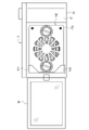
- FIG. 1 is a diagram showing a digital camera
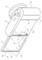
- FIG. FIG. 10 is a diagram showing a state in which the mobile monitor has moved from a position facing the mounting surface; 1 shows a digital camera system;
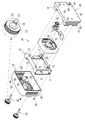
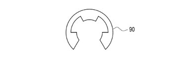
- FIG. It is a front exploded perspective view of a cooling device. It is a back exploded perspective view of a cooling device. It is a trihedral view of a heat sink. It is a sectional view of a cooling device. It is a figure which shows an E-shaped retaining ring.
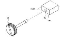
- FIG. 4 is an explanatory diagram of the arrangement position of a power receiving connector; It is a figure which shows 2nd Embodiment which penetrates a fin and provides an insertion hole.
- FIG. 10 is a diagram showing a digital camera system including a digital camera having grooves formed on a mounting surface and a cooling device according to a third embodiment;
- Fig. 3 shows a cooling device of a third embodiment with elastic sheets;
- FIG. 10 is a diagram showing another example of an elastic sheet;
- FIG. 11 shows a cooling device according to a fourth embodiment with a connector cover; It is a figure which shows the positional relationship of a connector cover and its accommodating part.
- FIG. 10 is a view showing a cooling device of a fifth embodiment with rubber cushions attached to the sides;
- FIG. 11 shows a cooling device of a fifth embodiment with rubber covers attached to the sides;
- FIG. 10 is a diagram showing another example of an attachment mechanism;
- FIG. 10 is a diagram showing still another example of the attachment mechanism;
- the digital camera 2 includes a camera body 10 and a lens barrel 11 provided in front of the camera body 10 .
- the lens barrel 11 has a lens group that guides subject light representing a subject to the imaging element 12 in the camera body 10 .
- the imaging element 12 is, for example, a CMOS (Complementary Metal Oxide Semiconductor) image sensor or a CCD (Charge Coupled Device) image sensor.
- the imaging element 12 has a rectangular imaging surface for imaging a subject. The imaging surface receives subject light. As is well known, pixels that photoelectrically convert received subject light and output electric signals are arranged in a two-dimensional pattern on the imaging surface.
- the camera body 10 also incorporates a CPU (Central Processing Unit) 13 that controls the operation of the imaging device 12 .
- the front surface of the camera body 10 is also provided with a strobe light irradiation window and the like.
- the digital camera 2 is an example of an “electronic device” and an “imaging device” according to the technology of the present disclosure.
- the CPU 13 is an example of a “processor” according to the technology of the present disclosure.
- a power switch 14 , a mode dial 15 , and a release button 16 arranged in the center of the mode dial 15 are provided on the upper surface of the camera body 10 .
- the power switch 14 is operated to turn on/off the power of the digital camera 2 .
- the mode dial 15 is rotated to switch between various operation modes of the digital camera 2, such as a still image shooting mode, a moving image shooting mode, and an image playback mode.
- the release button 16 is pressed when taking an image.
- the camera body 10 is also provided with operation members such as a menu button and a cross key.
- a movable monitor 18 is provided on the rear surface 17 of the camera body 10 .
- a portable monitor 18 is attached to the back surface 17 via hinges 19 .
- the mobile monitor 18 can rotate 180° in the horizontal direction indicated by the arrow A1 (the direction to open left and the direction to close to the right) with the hinge 19 as a fulcrum.
- the mobile monitor 18 can be rotated 360 degrees in the vertical direction indicated by the arrow A2. That is, the mobile monitor 18 is a vari-angle monitor.
- the movable monitor 18 opened to the left is indicated by a solid line
- the movable monitor 18 rotated upward while being opened to the left is indicated by a broken line.
- the surface of the rear surface 17 facing the mobile monitor 18 when the mobile monitor 18 is in the position shown in FIG. 1 and exposed when the mobile monitor 18 is in the position shown in FIG. 2 (hereinafter referred to as the mounting surface). 17A is provided with a pair of screw holes 20 for detachably mounting a cooling device 25 (see FIG. 3), which will be described later.
- the screw holes 20 are arranged at substantially the vertical center of the mounting surface 17A and symmetrically with respect to the horizontal center of the mounting surface 17A.
- a power supply connector 21 for supplying power to the cooling device 25 is provided at the left end of the mounting surface 17A.
- the screw hole 20 is an example of the "first attachment mechanism" and the "fitting portion" according to the technology of the present disclosure.
- a cooling device 25 is attached to the mounting surface 17A as necessary.
- the cooling device 25 has an attachment mechanism 26 that engages with the screw hole 20, and is detachably attached to the attachment surface 17A.
- the cooling device 25 and the digital camera 2 constitute a digital camera system 30 .
- the digital camera system 30 is an example of an "electronic equipment system” according to the technology of the present disclosure.
- the attachment mechanism 26 is an example of a "second attachment mechanism" according to the technology of the present disclosure.
- the cooling device 25 includes a pair of device mounting screws 35, a housing 36, a holding frame 37, a fan 38, a power receiving unit 39, and a heat sink 40.
- Housing 36 covers holding frame 37 , fan 38 , power receiving unit 39 , and heat sink 40 .
- the device mounting screw 35 is included in the mounting mechanism 26.
- the device mounting screw 35 has an elongated cylindrical screw body 50 and a disk-shaped screw head 51 provided at one end of the screw body 50 and having a larger diameter than the screw body 50 .
- the screw main body 50 is made of metal such as stainless steel.
- the screw body 50 is composed of a threaded portion 52 at the tip, a trunk portion 53 in the middle, and a neck portion 54 at the base.
- the screw portion 52 is screwed into the screw hole 20 of the mounting surface 17A.
- the barrel portion 53 has a slightly smaller diameter than the threaded portion 52 and the neck portion 54 .
- the body portion 53 is not threaded.
- a circumferential groove 55 is formed in the neck portion 54 .
- the threaded portion 52 is an example of a “fitted portion” according to the technology of the present disclosure.
- the screw head 51 is made of a resin with high hardness and high heat resistance, such as phenol resin.
- the screw head 51 is rotated by the user when the cooling device 25 is attached or detached.
- the screw head 51 has a size that can be easily gripped by a user's fingers, and a non-slip groove is formed on the entire peripheral surface of the screw head 51 . Further, the screw head 51 is formed with a minus groove for inserting a rotary jig or the like.
- a pair of insertion holes 60 through which the screw body 50 of the device mounting screw 35 is inserted is formed in the housing 36 .
- a recess 61 is formed around the insertion hole 60 to accommodate the screw head 51 of the device mounting screw 35 .
- the screw body 50 is arranged inside the housing 36, and the screw head 51 is arranged outside the housing 36 (see also FIG. 7).
- Insertion holes 63 through which housing mounting screws 62 are inserted are formed in the four corners of the housing 36 .
- a plurality of fan-shaped intake ports 64 are radially formed in the central portion of the front surface of the housing 36 .
- a plurality of slit-shaped intake ports 65 are formed on both side surfaces of the housing 36 .
- the holding frame 37 holds the fan 38 and the power receiving unit 39 .
- a pair of insertion holes 70 through which the screw body portion 50 of the device mounting screw 35 is inserted is formed at positions of the holding frame 37 corresponding to the insertion holes 60 .
- a screw hole 71 is formed at a position of the holding frame 37 corresponding to the insertion hole 63 .
- a housing mounting screw 62 is screwed into the screw hole 71 .
- four insertion holes 72 are formed at positions of the holding frame 37 one turn inside the screw holes 71 .
- a holding frame attachment screw 73 is inserted through the insertion hole 72 .
- the fan 38 sends cooling air to the heat sink 40. More specifically, the fan 38 is an axial fan that draws in air taken into the interior of the cooling device 25 through the air inlets 64 and 65 and discharges the air toward the heat sink 40 .
- the power receiving unit 39 has a power receiving connector 75 and a flexible substrate 76 .
- the power receiving connector 75 is connected to the power supply connector 21 on the mounting surface 17A when the cooling device 25 is mounted on the mounting surface 17A.
- the power receiving connector 75 receives driving power for the fan 38 from the digital camera 2 via the power feeding connector 21 .
- the flexible substrate 76 has one end connected to the power receiving connector 75 and the other end connected to the fan 38 .
- a drive circuit and a power supply circuit for the fan 38 are mounted on the flexible substrate 76 .
- a plurality of fins 81 for heat dissipation are formed on the front surface 80 of the heat sink 40 facing the fan 38 .
- the fins 81 stand upright in the front-rear direction, extend in the left-right direction, and are arranged vertically at substantially equal intervals.
- a rear surface 82 of the heat sink 40 opposite to the front surface 80 on which the fins 81 are formed contacts the mounting surface 17A when the cooling device 25 is mounted.
- a pair of through holes 83 through which the screw body portions 50 of the device mounting screws 35 are inserted are formed at positions of the heat sink 40 corresponding to the through holes 60 and 70 .
- Insertion hole 83 is included in attachment mechanism 26 . Since the insertion hole 83 is provided in the heat sink 40, which is an example of the "fin formation area" according to the technology of the present disclosure, the attachment mechanism 26 overlaps with the "fin formation area.”
- a screw hole 84 is formed at a position of the heat sink 40 corresponding to the insertion hole 72 .
- a holding frame mounting screw 73 is screwed into the screw hole 84 . As a result, the holding frame 37, the heat sink 40, and the fan 38 are integrated.
- a U-shaped connector placement portion 85 is formed in plan view.
- the connector placement portion 85 is provided by cutting out a portion of the left end of the heat sink 40 .
- a power receiving connector 75 is arranged in the connector arrangement portion 85 (see FIG. 9).
- the device mounting screws 35 and the insertion holes 83 included in the mounting mechanism 26 are provided at opposite positions on the left and right with the fan 38 interposed therebetween.
- the fin 81 includes a fin 811 of height H1, a fin 812A of height H2A, a fin 813 of height H3, and fins 814 formed at the upper and lower ends.
- the insertion hole 83 is provided between two adjacent fins 812A.
- the height H2A of the fin 812A is lower than the height H1 of the fin 811 (H2A ⁇ H1).
- the fins 813 overlap the fan 38 in plan view.
- the height H3 of the fin 813 is lower than the height H1 of the fin 811 (H3 ⁇ H1).
- an E-shaped retaining ring (also called an E-ring) 90 shown in FIG. 8 is fitted into the groove 55 of the neck 54 of the device mounting screw 35 .
- Neck 54 is located between housing 36 and fin 812A. Therefore, the E-shaped retaining ring 90 is provided between the housing 36 and the fins 812A.
- the diameter of the E-shaped retaining ring 90 is smaller than the through hole 70 but larger than the through hole 60 . Therefore, the device mounting screw 35 can move back and forth by the stroke of the insertion hole 60 and the insertion hole 70 . Further, the E-shaped retaining ring 90 prevents the screw main body 50 of the device mounting screw 35 from falling out of the insertion hole 60 and thus the housing 36 .
- a pin or the like inserted into a through hole formed in the neck portion 54 may be used as the member for preventing the device mounting screw 35 from coming off.
- the heat source 95 of the digital camera 2 is positioned substantially at the center of the camera body 10 .
- the heat source 95 includes, for example, the imaging element 12, a drive circuit for the imaging element 12, a power supply circuit, and the CPU 13.
- the cooling device 25 is attached at a position shifted to the left from the center of the camera body 10 . Therefore, when viewed from the cooling device 25, the heat source 95 is shifted to the right.
- the heat sink 40 has a first formation region 96 for the fins 81 arranged on the right side of the fan 38 and a second formation region 97 for the fins 81 arranged on the left side of the fan 38.
- have Most of the heat source 95 is in the first forming area 96 on the right. In other words, the heat source 95 overlaps the first formation region 96 more than the second formation region 97 .
- the connector placement portion 85 of the heat sink 40 and, by extension, the power receiving connector 75 are located in the second formation area 97 on the left side.
- the area of the first formation region 96 is larger than the area S2 of the second formation region 97 (S2 ⁇ S1) because the connector placement portion 85 is not provided.
- S2 ⁇ S1 the area S2 of the second formation region 97
- the connector placement portion 85 and thus the power receiving connector 75 are placed below the center C of the heat sink 40 .
- the right side with respect to the fan 38 is an example of the "first side” according to the technology of the present disclosure.
- the left side of the fan 38 is an example of the "second side” according to the technology of the present disclosure.
- the heat source 95 may include at least one of the image sensor 12 and the CPU 13 .
- the cooling device 25 is intended to more efficiently cool the heat source 95 near the back surface 17 inside the digital camera 2 , so based on FIG. It is preferable that the CPU 13 is close to
- the user moves the mobile monitor 18 from the rear surface 17 to the desired position and angle.
- the user selects a moving image shooting mode with the mode dial 15 and shoots a moving image (for example, shooting a moving image at 120 frames per second (4K/120p) with an image quality equivalent to 4K resolution)
- the heat source 95 especially generates heat.
- the cooling device 25 is attached to the attachment surface 17A.
- the user connects the power receiving connector 75 to the power supply connector 21 of the mounting surface 17A, and screws the screw portion 52 of the device mounting screw 35 into the screw hole 20 of the mounting surface 17A.
- the back surface 82 of the heat sink 40 is in contact with the mounting surface 17A. Therefore, the heat generated by the heat source 95 is transmitted from the mounting surface 17A to the heat sink 40 and radiated by the fins 81 of the heat sink 40. As shown in FIG. Driving power is supplied through the power receiving connector 75 to operate the fan 38 . As a result, cooling air is sent from the fan 38 to the heat sink 40, and the heat transferred to the heat sink 40 is cooled.
- the cooling device 25 includes the heat sink 40 formed with a plurality of heat radiation fins 81 and the attachment mechanism 26 for detachably attaching the heat sink 40 to the attachment surface 17A of the digital camera 2. .
- the insertion holes 83 that are part of the mounting mechanism 26 overlap the areas where the fins 81 are formed. Therefore, the attachment mechanism 26 does not sacrifice the fins 81 . Therefore, it is possible to cool the digital camera 2 when necessary, and to prevent deterioration of the cooling performance.
- the mounting mechanism 26 includes insertion holes 83 provided in the formation area of the fins 81 and through which the device mounting screws 35 are inserted. Therefore, the mounting mechanism 26 can have a simple structure.
- the insertion hole 83 is provided between two adjacent fins 812A. Therefore, the insertion hole 83 can be easily formed.
- the device mounting screw 35 is provided with a screw body portion 50 that is inserted through the insertion hole 83 and one end of the screw body portion 50, and is operated by the user when the heat sink 40 (cooling device 25) is attached or detached. and a screw head 51 that is Therefore, the heat sink 40 (cooling device 25) can be easily attached and detached.
- the cooling device 25 has a housing 36 that covers the heat sink 40 . Further, as shown in FIG. 7, the screw head 51 is arranged outside the housing 36 and the screw main body 50 is arranged inside the housing 36 . An E-shaped retaining ring 90 is attached to the neck portion 54 which is the boundary portion between the screw main body portion 50 and the screw head portion 51 as a fall prevention member for preventing the device mounting screw 35 from falling out of the housing 36 . Therefore, it is possible to prevent the device mounting screws 35 from coming off the housing 36 .
- the housing 36 covers not only the heat sink 40 but also the holding frame 37 , the fan 38 , and the power receiving unit 39 , it still covers the heat sink 40 .
- the fins 81 include fins 811 and fins 812A lower in height than the fins 811.
- Fin 812A is a fin adjacent to insertion hole 83 . Therefore, a space can be secured on the front surface 80 side of the fin 812A.
- the neck 54 is arranged in this space. Therefore, by fitting the E-shaped snap ring 90 into the groove 55 of the neck portion 54, it is possible to prevent the device mounting screw 35 from coming off.
- the device mounting screw 35 has a screw main body 50 made of metal. Therefore, like the fins 81 of the heat sink 40, the screw main body 50 can function as a heat dissipation member.
- the device mounting screw 35 has a screw head 51 made of a highly heat-resistant resin. Therefore, the heat from the screw body portion 50 is not transmitted to the screw head portion 51 . Therefore, the user's fingers holding the screw head 51 can be protected from heat.
- the cooling device 25 has a fan 38 that sends cooling air to the heat sink 40 .
- the pair of mounting mechanisms 26 are provided at positions sandwiching the fan 38 . Therefore, the feeling of stability when the cooling device 25 is attached to the attachment surface 17A is increased. Rattling of the cooling device 25 due to vibration of the fan 38 can be suppressed.
- the fan 38 is attached to the area where the fins 81 are formed.
- the fins 81 include fins 811 and fins 813 lower in height than the fins 811 .
- the fins 813 overlap the fan 38 in plan view. Therefore, a space for the fan 38 can be secured on the front surface 80 side of the fins 813 . This can contribute to making the cooling device 25 compact.
- the digital camera system 30 includes a digital camera 2 equipped with a mobile monitor 18 and a cooling device 25 for cooling the heat generated by the digital camera 2.
- the digital camera 2 has a problem of heat generation, especially during moving image shooting. Therefore, the heat generated by the digital camera 2 can be efficiently cooled by the cooling device 25 when necessary, such as when photographing a moving image.
- the digital camera 2 includes a mobile monitor 18 and screw holes 20 on the mounting surface 17A.
- the cooling device 25 has an attachment mechanism 26 for detachably attaching to the digital camera 2 .
- the attachment mechanism 26 is attached to the screw hole 20 exposed by moving the mobile monitor from the position facing the attachment surface 17A.
- the mounting surface 17A is normally covered with a mobile monitor 18.
- the screw holes 20 are also normally hidden by the mobile monitor 18 . Therefore, it looks better than a digital camera in which the screw holes 20 are always exposed.
- there is less chance of foreign matter such as dust entering the screw hole 20 there is less risk of failure compared to a digital camera in which the screw hole 20 is always exposed, and maintainability is good.
- the digital camera 2 includes a threaded hole 20 that is a fitting portion, and the mounting mechanism 26 of the cooling device 25 includes a threaded portion 52 that is a fitted portion that fits into the threaded hole 20 . Therefore, the cooling device 25 can be attached to and detached from the digital camera 2 with a simple structure.
- the mobile monitor 18 is a vari-angle monitor. Therefore, compared to the tilt system in which the mobile monitor is pulled out rearward from the rear surface and rotated in the vertical direction, the mounting surface 17A has a larger area, and the contact surface of the cooling device 25 with the heat sink 40 can be secured correspondingly wider. can. Therefore, it is possible to further improve the cooling efficiency.
- the heat sink 40 has a connector placement portion 85.
- a power receiving connector 75 for receiving power for driving the fan 38 from the digital camera 2 is arranged in the connector arrangement portion 85 .
- the heat source 95 of the digital camera 2 is on the right side of the first formation area 96 side
- the power receiving connector 75 is on the left side of the second formation area 97 side.
- the area S1 of the first formation region 96 is larger than the area S2 of the second formation region.
- the power receiving connector 75 is arranged below the center C of the heat sink 40 .
- the part where the connector placement part 85 is formed has no fins 81, so the cooling performance is inferior. Therefore, if the connector placement portion 85 is formed in the same first formation region 96 as the heat source 95 that requires cooling, there is a concern that the cooling efficiency will decrease. However, in this example, since the connector placement portion 85 is formed in the second formation region 97 opposite to the first formation region 96 to place the power receiving connector 75, there is little concern that the cooling efficiency will be lowered.
- the electronic device is the digital camera 2 having the image sensor 12 that captures moving images
- the heat source 95 is the image sensor 12 and the CPU 13 that processes the moving images. Therefore, the cooling device 25 can efficiently cool the moving image when the heat source 95 is particularly concerned about heat generation.
- the insertion hole 83 is provided between the two adjacent fins 812A in the first embodiment, the configuration is not limited to this. As an example, like the heat sink 100 shown in FIGS. 10 and 11, the insertion holes 83 may be provided through the fins 812B.
- the height H2B of the fin 812B is lower than the height H1 of the fin 811 (H2B ⁇ H1).
- the insertion holes 83 pass through the fins 812B. Therefore, the screw body portion 50 of the device mounting screw 35 is not arranged between the fins 81 . Therefore, it is possible to improve the passage of air compared to the above-described first embodiment in which passage of air between the fins 812A is poor due to the screw body portion 50 .
- the width in the vertical direction of the portion where the insertion hole 83 is formed may be made wider than the other portions.
- a digital camera 110 has a concave portion 111 formed in a mounting surface 17A.
- the concave portion 111 is a step for preventing the corner of the movable monitor 18 from coming into contact with the mounting surface 17A when the movable monitor 18 is rotated in the vertical direction at an incomplete horizontal opening angle.
- the concave portion 111 is an example of a “step” according to the technology of the present disclosure.
- the cooling device 115 constitutes a digital camera system 120 together with the digital camera 110 .
- the cooling device 115 has the same basic configuration as the cooling device 25 of the first embodiment, except that an elastic sheet 116 is adhered for close contact with the recess 111 of the mounting surface 17A. 25 different.
- the elastic sheet 116 has elasticity, as its name suggests, and relatively high thermal conductivity.
- the elastic sheet 116 is, for example, a graphite sheet.
- the elastic sheet 116 is attached to the back surface 82 of the heat sink 40 that contacts the mounting surface 17A.
- the elastic sheet 116 substantially covers the rear surface 82, but slightly exposes a portion thereof. That is, the elastic sheet 116 has a circular hole 121 cut to fit the insertion hole 83 and a rectangular corner 122 cut to fit the power receiving connector 75 . Since the insertion hole 83 is included in the attachment mechanism 26 , the elastic sheet 116 is not provided in the attachment mechanism 26 portion due to the hole 121 . Also, the elastic sheet 116 is not provided at the power receiving connector 75 due to the corner portion 122 .
- the cooling device 115 of the third embodiment is provided on the rear surface 82 of the heat sink 40, which is the mounting surface to the mounting surface 17A, and includes the elastic sheet 116 for closely contacting the mounting surface 17A.
- the elastic sheet 116 is in close contact with the recess 111 of the mounting surface 17A. Therefore, even if the mounting surface 17A has a step such as the concave portion 111, the adhesion of the heat sink 40 to the mounting surface 17A can be enhanced, and more heat can be transferred from the mounting surface 17A to the heat sink 40. can be made
- the elastic sheet 116 is not provided in the mounting mechanism 26 portion. Therefore, the elastic sheet 116 does not hinder the attachment of the cooling device 115 to the attachment surface 17A. Also, the elastic sheet 116 is not provided at the power receiving connector 75 portion. Therefore, the elastic sheet 116 does not hinder the power supply to the fan 38 .
- an elastic sheet 126 having a size that fits inside the insertion hole 83 and the power receiving connector 75 may be used. By doing so, the elastic sheet 126 is also not provided in the mounting mechanism 26 and the power receiving connector 75 .
- a convex portion corresponding to the concave portion 111 may be formed on the rear surface 82 of the heat sink 40.
- this method requires time and effort to process the back surface 82, the method of attaching the elastic sheet 116 or 126 is preferable.
- the cooling device 130 of the fourth embodiment includes a connector cover 131 detachably attached to the power receiving connector 75 .
- the connector cover 131 is put on the power receiving connector 75 to cover the power receiving connector 75 when the cooling device 130 is not in use.
- a housing portion 132 is provided in a portion of the housing 36 facing the power receiving connector 75 and between the power receiving connector 75 and the housing 36 .
- Accommodating portion 132 accommodates connector cover 131 removed from power receiving connector 75 when cooling device 130 is used.
- a holding mechanism (not shown) that holds the housed power receiving connector 75 is provided in the housing portion 132 .
- the holding mechanism presses the connector cover 131 against the wall surface of the housing portion 132 by the force of a spring, for example.
- the holding mechanism is a shutter that opens and closes the opening of the housing portion 132 .
- the holding mechanism may attract and hold the connector cover 131 by magnetic force. When the connector cover 131 is taken out from the accommodating portion 132, the holding by the holding mechanism is released by operating a button or the like.
- the cooling device 130 of the fourth embodiment includes the connector cover 131 that covers the power receiving connector 75 when not in use, and the housing portion 132 that houses the connector cover 131 removed from the power receiving connector 75 when in use. Since the connector cover 131 reduces the chances of dust or other foreign matter entering the power receiving connector 75 when not in use, it is possible to reduce the risk of failure and contribute to improved maintainability. In addition, since the accommodation portion 132 provides a place for the connector cover 131 removed from the power receiving connector 75 to go, loss of the connector cover 131 can be prevented.
- the accommodation portion 132 is provided between the power receiving connector 75 and the housing 36 . Therefore, access is easy when covering the power receiving connector 75 with the connector cover 131 when not in use, and when housing the connector cover 131 removed from the power receiving connector 75 when in use.
- the cooling device 135 has a plurality of trapezoidal cylindrical rubber cushions 137 attached to the side portion 136 .
- the side portion 136 is a portion facing the mobile monitor 18 when the mobile monitor 18 moves from the position facing the mounting surface 17A.
- the rubber cushion 137 is an example of a “protective member” and a “convex member” according to the technology of the present disclosure. Due to the presence of this rubber cushion 137, even if the mobile monitor 18 is accidentally hit against the side portion 136, the mobile monitor 18 will not be damaged. Therefore, the mobile monitor 18 can be protected.
- a rubber cover 142 that covers the side portion 141 may be employed instead of the rubber cushion 137 .
- the rubber cover 142 is an example of a “protective member” and a “coating member” according to the technology of the present disclosure. According to the rubber cover 142, compared with the rubber cushion 137, the amount of protrusion to the outside is reduced, so the appearance can be improved.
- the device mounting screw 35 is exemplified as the mounting mechanism 26 in each of the above embodiments, it is not limited to this.
- a device mounting pin 150 shown in FIG. 19 may be used.
- the device mounting pin 150 is a so-called rotary lock pin, and has a pin body portion 151 and a rotary knob 152 provided at one end of the pin body portion 151 .
- the pin main body 151 is made of metal, and the rotary knob 152 is made of resin with high hardness and high heat resistance.
- the rotation knob 152 is rotated by the user when the heat sink 40 is attached or detached.
- a pair of columnar protrusions 154 are formed at positions facing each other on the tip portion 153 of the pin main body portion 151 .
- the projection 154 (pin main body portion 151) rotates 90° in conjunction with the rotation operation of the rotary knob 152.
- the tip portion 153 is an example of a “fitted portion” according to the technology of the present disclosure.
- the mounting surface 17A is formed with a fitting hole 155 into which the tip portion 153 is fitted.
- the fitting hole 155 has a shape following the cross-sectional shape of the tip portion 153 including the protrusion 154 .
- a circumferential groove 156 in which the projection 154 is accommodated is formed inside the fitting hole 155 .
- the fitting hole 155 and the groove 156 are examples of the “fitting portion” according to the technology of the present disclosure.
- the rotation knob 152 When attaching the cooling device to the mounting surface 17A, after inserting the tip portion 153 of the pin main body portion 151 into the fitting hole 155, the rotation knob 152 is rotated to rotate the projection 154 by 90°, thereby 154 fits into groove 156 .
- the protrusion 154 is rotated 90 degrees in the opposite direction by rotating the rotation knob 152 in the opposite direction, thereby releasing the engagement between the protrusion 154 and the groove 156. After that, the pin body portion 151 is pulled up from the fitting hole 155 .
- a device mounting pin 160 shown in FIG. 20 may be used.
- the device mounting pin 160 is a so-called ball lock pin, and has a pin body portion 161 and a knob 162 provided at one end of the pin body portion 161 .
- a button 163 is provided on the knob 162 .
- the pin main body 161 is made of metal, and the knob 162 is made of resin with high hardness and high heat resistance. The button 163 is pressed by the user when the heat sink 40 is attached or detached.
- Four balls 165 are attached to the tip portion 164 of the pin main body portion 161 at, for example, 90° intervals in the circumferential direction. The ball 165 can appear and disappear from the tip portion 164 .
- the ball 165 protrudes from the tip portion 164 when the button 163 is not pressed.
- the ball 165 sinks into the tip portion 164 in conjunction with the pressing operation of the button 163 .
- the tip portion 164 is an example of a “fitted portion” according to the technology of the present disclosure.
- the mounting surface 17A is formed with a fitting hole 166 into which the tip portion 164 is fitted.
- the fitting hole 166 has a shape following the cross-sectional shape of the tip portion 164 in which the ball 165 is sunk, that is, has a circular shape.
- a circumferential groove 167 in which the ball 165 is accommodated is formed inside the fitting hole 166 .
- the fitting hole 166 and the groove 167 are examples of the "fitting portion" according to the technology of the present disclosure.
- the button 163 When attaching the cooling device to the mounting surface 17A, the button 163 is pressed to make the ball 165 sink into the tip portion 164. After that, the tip portion 164 is inserted into the fitting hole 166 . After that, the button 163 is released to project the ball 165 from the tip portion 164 , thereby fitting the ball 165 into the groove 167 . On the other hand, when the cooling device is removed from the mounting surface 17A, the button 163 is pressed to make the ball 165 sink into the tip portion 164, thereby releasing the engagement between the ball 165 and the groove 167. After that, the pin body portion 161 is pulled up from the fitting hole 166 .
- the number of mounting mechanisms 26 is not limited to two as illustrated.
- four attachment mechanisms 26 may be arranged at the four corners of the cooling device.
- the mobile monitor 18 is not limited to the vari-angle type illustrated in each of the above embodiments, and may be a tilt type. Also, the fan 38 may be omitted.
- the processor is not limited to the illustrated CPU 13.
- specification of programmable logic devices PLDs
- ASICs Application Specific Integrated Circuits
- FPGAs Field Programmable Gate Arrays
- a dedicated electric circuit or the like which is a processor having a circuit configuration specially designed to execute the processing of , may also be used.
- the digital camera 2 has been exemplified as an electronic device, it is not limited to this.
- the techniques of the present disclosure can be applied to any electronic device with a mobile monitor that may require cooling.
- a and/or B is synonymous with “at least one of A and B.” That is, “A and/or B” means that only A, only B, or a combination of A and B may be used.
- a and/or B means that only A, only B, or a combination of A and B may be used.
Landscapes
- Engineering & Computer Science (AREA)
- Physics & Mathematics (AREA)
- Signal Processing (AREA)
- Multimedia (AREA)
- General Physics & Mathematics (AREA)
- Microelectronics & Electronic Packaging (AREA)
- Thermal Sciences (AREA)
- Electromagnetism (AREA)
- Aviation & Aerospace Engineering (AREA)
- Studio Devices (AREA)
- Cooling Or The Like Of Electrical Apparatus (AREA)
- Indication In Cameras, And Counting Of Exposures (AREA)
- Accessories Of Cameras (AREA)
Priority Applications (4)
| Application Number | Priority Date | Filing Date | Title |
|---|---|---|---|
| JP2023508739A JP7775285B2 (ja) | 2021-03-25 | 2022-02-01 | 冷却装置、および電子機器システム |
| US18/464,260 US12449721B2 (en) | 2021-03-25 | 2023-09-10 | Cooling device and electronic apparatus system |
| US19/328,268 US20260010058A1 (en) | 2021-03-25 | 2025-09-15 | Cooling device and electronic apparatus system |
| JP2025187325A JP2026016766A (ja) | 2021-03-25 | 2025-11-06 | 冷却装置、および電子機器システム |
Applications Claiming Priority (2)
| Application Number | Priority Date | Filing Date | Title |
|---|---|---|---|
| JP2021051662 | 2021-03-25 | ||
| JP2021-051662 | 2021-03-25 |
Related Child Applications (1)
| Application Number | Title | Priority Date | Filing Date |
|---|---|---|---|
| US18/464,260 Continuation US12449721B2 (en) | 2021-03-25 | 2023-09-10 | Cooling device and electronic apparatus system |
Publications (1)
| Publication Number | Publication Date |
|---|---|
| WO2022201883A1 true WO2022201883A1 (ja) | 2022-09-29 |
Family
ID=83396813
Family Applications (1)
| Application Number | Title | Priority Date | Filing Date |
|---|---|---|---|
| PCT/JP2022/003879 Ceased WO2022201883A1 (ja) | 2021-03-25 | 2022-02-01 | 冷却装置、および電子機器システム |
Country Status (3)
| Country | Link |
|---|---|
| US (2) | US12449721B2 (https=) |
| JP (2) | JP7775285B2 (https=) |
| WO (1) | WO2022201883A1 (https=) |
Cited By (1)
| Publication number | Priority date | Publication date | Assignee | Title |
|---|---|---|---|---|
| EP4391567A1 (en) * | 2022-12-22 | 2024-06-26 | Canon Kabushiki Kaisha | Control apparatus, image capturing apparatus, control method, and program |
Families Citing this family (2)
| Publication number | Priority date | Publication date | Assignee | Title |
|---|---|---|---|---|
| JP2025051187A (ja) * | 2023-09-25 | 2025-04-04 | パナソニックIpマネジメント株式会社 | 撮像装置および放熱ユニット |
| JP2025159544A (ja) * | 2024-04-08 | 2025-10-21 | キヤノン株式会社 | 電子機器、冷却装置、および電子機器システム |
Citations (6)
| Publication number | Priority date | Publication date | Assignee | Title |
|---|---|---|---|---|
| JPH07211829A (ja) * | 1994-01-20 | 1995-08-11 | Sanyo Denki Co Ltd | 電子部品冷却装置 |
| JPH08162788A (ja) * | 1994-12-01 | 1996-06-21 | Pfu Ltd | ファン付きヒートシンク |
| JPH10256446A (ja) * | 1998-04-20 | 1998-09-25 | Fujitsu Ltd | ヒートシンク |
| JP2007180706A (ja) * | 2005-12-27 | 2007-07-12 | Sony Corp | 撮像装置 |
| JP2008277355A (ja) * | 2007-04-25 | 2008-11-13 | Toshiba Corp | 冷却装置および電子機器 |
| JP2012173591A (ja) * | 2011-02-23 | 2012-09-10 | Nikon Corp | 電子機器 |
Family Cites Families (3)
| Publication number | Priority date | Publication date | Assignee | Title |
|---|---|---|---|---|
| JP2019114893A (ja) | 2017-12-22 | 2019-07-11 | キヤノン株式会社 | 撮像装置 |
| JP2019219493A (ja) * | 2018-06-19 | 2019-12-26 | キヤノン株式会社 | 電子機器 |
| US11190671B2 (en) * | 2019-04-23 | 2021-11-30 | Panasonic Intellectual Property Management Co., Ltd. | Imaging apparatus |
-
2022
- 2022-02-01 WO PCT/JP2022/003879 patent/WO2022201883A1/ja not_active Ceased
- 2022-02-01 JP JP2023508739A patent/JP7775285B2/ja active Active
-
2023
- 2023-09-10 US US18/464,260 patent/US12449721B2/en active Active
-
2025
- 2025-09-15 US US19/328,268 patent/US20260010058A1/en active Pending
- 2025-11-06 JP JP2025187325A patent/JP2026016766A/ja active Pending
Patent Citations (6)
| Publication number | Priority date | Publication date | Assignee | Title |
|---|---|---|---|---|
| JPH07211829A (ja) * | 1994-01-20 | 1995-08-11 | Sanyo Denki Co Ltd | 電子部品冷却装置 |
| JPH08162788A (ja) * | 1994-12-01 | 1996-06-21 | Pfu Ltd | ファン付きヒートシンク |
| JPH10256446A (ja) * | 1998-04-20 | 1998-09-25 | Fujitsu Ltd | ヒートシンク |
| JP2007180706A (ja) * | 2005-12-27 | 2007-07-12 | Sony Corp | 撮像装置 |
| JP2008277355A (ja) * | 2007-04-25 | 2008-11-13 | Toshiba Corp | 冷却装置および電子機器 |
| JP2012173591A (ja) * | 2011-02-23 | 2012-09-10 | Nikon Corp | 電子機器 |
Cited By (2)
| Publication number | Priority date | Publication date | Assignee | Title |
|---|---|---|---|---|
| EP4391567A1 (en) * | 2022-12-22 | 2024-06-26 | Canon Kabushiki Kaisha | Control apparatus, image capturing apparatus, control method, and program |
| US12452509B2 (en) | 2022-12-22 | 2025-10-21 | Canon Kabushiki Kaisha | Control apparatus, image capturing apparatus, control method, and storage medium |
Also Published As
| Publication number | Publication date |
|---|---|
| JP2026016766A (ja) | 2026-02-03 |
| US20230418137A1 (en) | 2023-12-28 |
| JPWO2022201883A1 (https=) | 2022-09-29 |
| JP7775285B2 (ja) | 2025-11-25 |
| US12449721B2 (en) | 2025-10-21 |
| US20260010058A1 (en) | 2026-01-08 |
Similar Documents
| Publication | Publication Date | Title |
|---|---|---|
| US12449721B2 (en) | Cooling device and electronic apparatus system | |
| CN101539711B (zh) | 数码相机 | |
| JP7076996B2 (ja) | 電子機器 | |
| JP7210166B2 (ja) | 撮像システム | |
| JP7362449B2 (ja) | 撮像装置 | |
| WO2022201882A1 (ja) | 冷却装置、および電子機器システム | |
| JP7646391B2 (ja) | 撮像装置及び操作部材 | |
| JP2009033547A (ja) | 電子機器 | |
| JP2007049369A (ja) | 撮像素子パッケージの保持構造、及びレンズユニット | |
| JP2017044795A (ja) | 撮像装置 | |
| JP2005328202A (ja) | デジタルカメラの放熱構造 | |
| JP5626568B2 (ja) | 携帯用電子機器 | |
| JP2019114893A (ja) | 撮像装置 | |
| JPWO2022201883A5 (https=) | ||
| JP6882093B2 (ja) | 撮像装置 | |
| US12619132B2 (en) | Cooling device and electronic apparatus system | |
| JP2019008052A (ja) | 撮像装置 | |
| JP2025085025A (ja) | 撮像装置 | |
| JP2014235206A (ja) | 撮像装置 | |
| JP7055369B2 (ja) | 撮像装置 | |
| JP6584455B2 (ja) | 電子機器 | |
| JP2020068442A (ja) | 撮像装置 | |
| JP2013098620A (ja) | 撮像装置 | |
| JP2021081620A (ja) | 電子機器 | |
| US12615423B2 (en) | Display device and imaging apparatus |
Legal Events
| Date | Code | Title | Description |
|---|---|---|---|
| 121 | Ep: the epo has been informed by wipo that ep was designated in this application |
Ref document number: 22774685 Country of ref document: EP Kind code of ref document: A1 |
|
| WWE | Wipo information: entry into national phase |
Ref document number: 2023508739 Country of ref document: JP |
|
| NENP | Non-entry into the national phase |
Ref country code: DE |
|
| 122 | Ep: pct application non-entry in european phase |
Ref document number: 22774685 Country of ref document: EP Kind code of ref document: A1 |