WO2022201883A1 - Cooling apparatus and electronic device system - Google Patents
Cooling apparatus and electronic device system Download PDFInfo
- Publication number
- WO2022201883A1 WO2022201883A1 PCT/JP2022/003879 JP2022003879W WO2022201883A1 WO 2022201883 A1 WO2022201883 A1 WO 2022201883A1 JP 2022003879 W JP2022003879 W JP 2022003879W WO 2022201883 A1 WO2022201883 A1 WO 2022201883A1
- Authority
- WO
- WIPO (PCT)
- Prior art keywords
- electronic device
- cooling device
- cooling
- mounting surface
- monitor
- Prior art date
Links
- 238000001816 cooling Methods 0.000 title claims abstract description 100
- 230000007246 mechanism Effects 0.000 claims abstract description 47
- 238000003384 imaging method Methods 0.000 claims description 27
- 238000000034 method Methods 0.000 claims description 8
- 230000001681 protective effect Effects 0.000 claims description 7
- 230000008569 process Effects 0.000 claims description 5
- 238000003780 insertion Methods 0.000 description 31
- 230000037431 insertion Effects 0.000 description 31
- 230000015572 biosynthetic process Effects 0.000 description 19
- 238000010586 diagram Methods 0.000 description 7
- 239000002184 metal Substances 0.000 description 4
- 230000009471 action Effects 0.000 description 3
- 230000006870 function Effects 0.000 description 3
- 229920005989 resin Polymers 0.000 description 3
- 239000011347 resin Substances 0.000 description 3
- 239000000758 substrate Substances 0.000 description 3
- 230000004308 accommodation Effects 0.000 description 2
- 239000000428 dust Substances 0.000 description 2
- 230000000694 effects Effects 0.000 description 2
- 230000017525 heat dissipation Effects 0.000 description 2
- 230000020169 heat generation Effects 0.000 description 2
- OKTJSMMVPCPJKN-UHFFFAOYSA-N Carbon Chemical compound [C] OKTJSMMVPCPJKN-UHFFFAOYSA-N 0.000 description 1
- 238000003491 array Methods 0.000 description 1
- 239000011248 coating agent Substances 0.000 description 1
- 238000000576 coating method Methods 0.000 description 1
- 230000000295 complement effect Effects 0.000 description 1
- 238000005520 cutting process Methods 0.000 description 1
- 230000006866 deterioration Effects 0.000 description 1
- 229910002804 graphite Inorganic materials 0.000 description 1
- 239000010439 graphite Substances 0.000 description 1
- 229920006015 heat resistant resin Polymers 0.000 description 1
- 238000004519 manufacturing process Methods 0.000 description 1
- 229910044991 metal oxide Inorganic materials 0.000 description 1
- 150000004706 metal oxides Chemical class 0.000 description 1
- 238000012986 modification Methods 0.000 description 1
- 230000004048 modification Effects 0.000 description 1
- 230000002093 peripheral effect Effects 0.000 description 1
- 239000005011 phenolic resin Substances 0.000 description 1
- 238000003825 pressing Methods 0.000 description 1
- 230000002265 prevention Effects 0.000 description 1
- 230000005855 radiation Effects 0.000 description 1
- 239000004065 semiconductor Substances 0.000 description 1
- 229910001220 stainless steel Inorganic materials 0.000 description 1
- 239000010935 stainless steel Substances 0.000 description 1
Images


Classifications
-
- G—PHYSICS
- G03—PHOTOGRAPHY; CINEMATOGRAPHY; ANALOGOUS TECHNIQUES USING WAVES OTHER THAN OPTICAL WAVES; ELECTROGRAPHY; HOLOGRAPHY
- G03B—APPARATUS OR ARRANGEMENTS FOR TAKING PHOTOGRAPHS OR FOR PROJECTING OR VIEWING THEM; APPARATUS OR ARRANGEMENTS EMPLOYING ANALOGOUS TECHNIQUES USING WAVES OTHER THAN OPTICAL WAVES; ACCESSORIES THEREFOR
- G03B17/00—Details of cameras or camera bodies; Accessories therefor
- G03B17/55—Details of cameras or camera bodies; Accessories therefor with provision for heating or cooling, e.g. in aircraft
-
- G—PHYSICS
- G03—PHOTOGRAPHY; CINEMATOGRAPHY; ANALOGOUS TECHNIQUES USING WAVES OTHER THAN OPTICAL WAVES; ELECTROGRAPHY; HOLOGRAPHY
- G03B—APPARATUS OR ARRANGEMENTS FOR TAKING PHOTOGRAPHS OR FOR PROJECTING OR VIEWING THEM; APPARATUS OR ARRANGEMENTS EMPLOYING ANALOGOUS TECHNIQUES USING WAVES OTHER THAN OPTICAL WAVES; ACCESSORIES THEREFOR
- G03B17/00—Details of cameras or camera bodies; Accessories therefor
- G03B17/56—Accessories
-
- H—ELECTRICITY
- H01—ELECTRIC ELEMENTS
- H01L—SEMICONDUCTOR DEVICES NOT COVERED BY CLASS H10
- H01L23/00—Details of semiconductor or other solid state devices
- H01L23/34—Arrangements for cooling, heating, ventilating or temperature compensation ; Temperature sensing arrangements
- H01L23/46—Arrangements for cooling, heating, ventilating or temperature compensation ; Temperature sensing arrangements involving the transfer of heat by flowing fluids
- H01L23/467—Arrangements for cooling, heating, ventilating or temperature compensation ; Temperature sensing arrangements involving the transfer of heat by flowing fluids by flowing gases, e.g. air
-
- H—ELECTRICITY
- H04—ELECTRIC COMMUNICATION TECHNIQUE
- H04N—PICTORIAL COMMUNICATION, e.g. TELEVISION
- H04N23/00—Cameras or camera modules comprising electronic image sensors; Control thereof
-
- H—ELECTRICITY
- H04—ELECTRIC COMMUNICATION TECHNIQUE
- H04N—PICTORIAL COMMUNICATION, e.g. TELEVISION
- H04N23/00—Cameras or camera modules comprising electronic image sensors; Control thereof
- H04N23/50—Constructional details
- H04N23/52—Elements optimising image sensor operation, e.g. for electromagnetic interference [EMI] protection or temperature control by heat transfer or cooling elements
-
- H—ELECTRICITY
- H05—ELECTRIC TECHNIQUES NOT OTHERWISE PROVIDED FOR
- H05K—PRINTED CIRCUITS; CASINGS OR CONSTRUCTIONAL DETAILS OF ELECTRIC APPARATUS; MANUFACTURE OF ASSEMBLAGES OF ELECTRICAL COMPONENTS
- H05K7/00—Constructional details common to different types of electric apparatus
- H05K7/20—Modifications to facilitate cooling, ventilating, or heating
- H05K7/20009—Modifications to facilitate cooling, ventilating, or heating using a gaseous coolant in electronic enclosures
- H05K7/20136—Forced ventilation, e.g. by fans
- H05K7/20154—Heat dissipaters coupled to components
Definitions
- the technology of the present disclosure relates to cooling devices and electronic equipment systems.
- Japanese Patent Application Laid-Open No. 2019-114893 discloses that in a first housing having an accessory mounting surface on one side of the exterior, a heat source element, a Peltier element, and an accessory mounting surface sandwiched between the heat source element and the Peltier element and a heat sink connected to the imaging device.
- the heat absorbing surface of the Peltier device abuts against the heat sink.
- the accessory mounting surface has an opening with which at least a portion of the Peltier element overlaps when projected from the normal direction of the accessory mounting surface.
- the imaging device described in Japanese Patent Laid-Open No. 2019-114893 can be mounted on the accessory mounting surface, and the heat generating surface of the Peltier element can be cooled by the second housing having cooling means.
- An embodiment according to the technology of the present disclosure provides a cooling device and an electronic equipment system that can cool an imaging device when necessary without spoiling the appearance of the imaging device.
- a cooling device is used in an electronic device that includes a mobile monitor and a first mounting mechanism on a mounting surface, and is a cooling device that cools heat generated by the electronic device.
- a second attachment mechanism is provided for enabling attachment, and the second attachment mechanism is attached to the first attachment mechanism exposed by moving the mobile monitor from a position facing the mounting surface.
- the first attachment mechanism includes a fitting portion
- the second attachment mechanism includes a fitted portion that fits into the fitting portion
- the mobile monitor is preferably a vari-angle monitor.
- a fan for sending cooling air
- a heat sink having fins in a first forming region arranged on a first side with respect to the fan and a second forming region arranged on a second side with respect to the fan;
- a power receiving connector for receiving driving power from the electronic device, the heat source of the electronic device is on the first side, the power receiving connector is on the second side, and the area of the first formation region is larger than the area of the second formation region. Large is preferred.
- the power receiving connector is preferably arranged below the center of the heat sink.
- the electronic device is an imaging device having an imaging device that captures a moving image
- the heat source is at least one of the imaging device and a processor that processes the moving image
- the protective member is preferably an elastic convex member or an elastic covering member.
- the cooling device When the cooling device is attached to the electronic device, it is preferable to have an elastic sheet that adheres to the mounting surface.
- the elastic sheet is in close contact with the steps of the mounting surface.
- An electronic device system of the present disclosure includes any of the cooling devices described above and an electronic device.
- the electronic equipment system of the present disclosure includes the above-described cooling device and electronic equipment, and the mobile monitor is a vari-angle monitor.
- the cooling device when the cooling device is attached to the electronic device, it is provided with an elastic sheet that comes into close contact with the mounting surface. It is preferable that the steps correspond to rotation of the angle system.
- An electronic device system of the present disclosure includes the cooling device described above and an electronic device, wherein the electronic device is an imaging device having an imaging device that captures a moving image, and the heat source of the electronic device is the imaging device and the moving image. At least one of the processors for performing image processing.
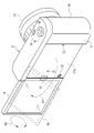
- FIG. 1 is a diagram showing a digital camera
- FIG. FIG. 10 is a diagram showing a state in which the mobile monitor has moved from a position facing the mounting surface; 1 shows a digital camera system;
- FIG. It is a front exploded perspective view of a cooling device. It is a back exploded perspective view of a cooling device. It is a trihedral view of a heat sink. It is a sectional view of a cooling device. It is a figure which shows an E-shaped retaining ring.
- FIG. 4 is an explanatory diagram of the arrangement position of a power receiving connector; It is a figure which shows 2nd Embodiment which penetrates a fin and provides an insertion hole.
- FIG. 10 is a diagram showing a digital camera system including a digital camera having grooves formed on a mounting surface and a cooling device according to a third embodiment;
- Fig. 3 shows a cooling device of a third embodiment with elastic sheets;
- FIG. 10 is a diagram showing another example of an elastic sheet;
- FIG. 11 shows a cooling device according to a fourth embodiment with a connector cover; It is a figure which shows the positional relationship of a connector cover and its accommodating part.
- FIG. 10 is a view showing a cooling device of a fifth embodiment with rubber cushions attached to the sides;
- FIG. 11 shows a cooling device of a fifth embodiment with rubber covers attached to the sides;
- FIG. 10 is a diagram showing another example of an attachment mechanism;
- FIG. 10 is a diagram showing still another example of the attachment mechanism;
- the digital camera 2 includes a camera body 10 and a lens barrel 11 provided in front of the camera body 10 .
- the lens barrel 11 has a lens group that guides subject light representing a subject to the imaging element 12 in the camera body 10 .
- the imaging element 12 is, for example, a CMOS (Complementary Metal Oxide Semiconductor) image sensor or a CCD (Charge Coupled Device) image sensor.
- the imaging element 12 has a rectangular imaging surface for imaging a subject. The imaging surface receives subject light. As is well known, pixels that photoelectrically convert received subject light and output electric signals are arranged in a two-dimensional pattern on the imaging surface.
- the camera body 10 also incorporates a CPU (Central Processing Unit) 13 that controls the operation of the imaging device 12 .
- the front surface of the camera body 10 is also provided with a strobe light irradiation window and the like.
- the digital camera 2 is an example of an “electronic device” and an “imaging device” according to the technology of the present disclosure.
- the CPU 13 is an example of a “processor” according to the technology of the present disclosure.
- a power switch 14 , a mode dial 15 , and a release button 16 arranged in the center of the mode dial 15 are provided on the upper surface of the camera body 10 .
- the power switch 14 is operated to turn on/off the power of the digital camera 2 .
- the mode dial 15 is rotated to switch between various operation modes of the digital camera 2, such as a still image shooting mode, a moving image shooting mode, and an image playback mode.
- the release button 16 is pressed when taking an image.
- the camera body 10 is also provided with operation members such as a menu button and a cross key.
- a movable monitor 18 is provided on the rear surface 17 of the camera body 10 .
- a portable monitor 18 is attached to the back surface 17 via hinges 19 .
- the mobile monitor 18 can rotate 180° in the horizontal direction indicated by the arrow A1 (the direction to open left and the direction to close to the right) with the hinge 19 as a fulcrum.
- the mobile monitor 18 can be rotated 360 degrees in the vertical direction indicated by the arrow A2. That is, the mobile monitor 18 is a vari-angle monitor.
- the movable monitor 18 opened to the left is indicated by a solid line
- the movable monitor 18 rotated upward while being opened to the left is indicated by a broken line.
- the surface of the rear surface 17 facing the mobile monitor 18 when the mobile monitor 18 is in the position shown in FIG. 1 and exposed when the mobile monitor 18 is in the position shown in FIG. 2 (hereinafter referred to as the mounting surface). 17A is provided with a pair of screw holes 20 for detachably mounting a cooling device 25 (see FIG. 3), which will be described later.
- the screw holes 20 are arranged at substantially the vertical center of the mounting surface 17A and symmetrically with respect to the horizontal center of the mounting surface 17A.
- a power supply connector 21 for supplying power to the cooling device 25 is provided at the left end of the mounting surface 17A.
- the screw hole 20 is an example of the "first attachment mechanism" and the "fitting portion" according to the technology of the present disclosure.
- a cooling device 25 is attached to the mounting surface 17A as necessary.
- the cooling device 25 has an attachment mechanism 26 that engages with the screw hole 20, and is detachably attached to the attachment surface 17A.
- the cooling device 25 and the digital camera 2 constitute a digital camera system 30 .
- the digital camera system 30 is an example of an "electronic equipment system” according to the technology of the present disclosure.
- the attachment mechanism 26 is an example of a "second attachment mechanism" according to the technology of the present disclosure.
- the cooling device 25 includes a pair of device mounting screws 35, a housing 36, a holding frame 37, a fan 38, a power receiving unit 39, and a heat sink 40.
- Housing 36 covers holding frame 37 , fan 38 , power receiving unit 39 , and heat sink 40 .
- the device mounting screw 35 is included in the mounting mechanism 26.
- the device mounting screw 35 has an elongated cylindrical screw body 50 and a disk-shaped screw head 51 provided at one end of the screw body 50 and having a larger diameter than the screw body 50 .
- the screw main body 50 is made of metal such as stainless steel.
- the screw body 50 is composed of a threaded portion 52 at the tip, a trunk portion 53 in the middle, and a neck portion 54 at the base.
- the screw portion 52 is screwed into the screw hole 20 of the mounting surface 17A.
- the barrel portion 53 has a slightly smaller diameter than the threaded portion 52 and the neck portion 54 .
- the body portion 53 is not threaded.
- a circumferential groove 55 is formed in the neck portion 54 .
- the threaded portion 52 is an example of a “fitted portion” according to the technology of the present disclosure.
- the screw head 51 is made of a resin with high hardness and high heat resistance, such as phenol resin.
- the screw head 51 is rotated by the user when the cooling device 25 is attached or detached.
- the screw head 51 has a size that can be easily gripped by a user's fingers, and a non-slip groove is formed on the entire peripheral surface of the screw head 51 . Further, the screw head 51 is formed with a minus groove for inserting a rotary jig or the like.
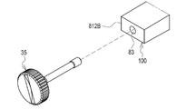
- a pair of insertion holes 60 through which the screw body 50 of the device mounting screw 35 is inserted is formed in the housing 36 .
- a recess 61 is formed around the insertion hole 60 to accommodate the screw head 51 of the device mounting screw 35 .
- the screw body 50 is arranged inside the housing 36, and the screw head 51 is arranged outside the housing 36 (see also FIG. 7).
- Insertion holes 63 through which housing mounting screws 62 are inserted are formed in the four corners of the housing 36 .
- a plurality of fan-shaped intake ports 64 are radially formed in the central portion of the front surface of the housing 36 .
- a plurality of slit-shaped intake ports 65 are formed on both side surfaces of the housing 36 .
- the holding frame 37 holds the fan 38 and the power receiving unit 39 .
- a pair of insertion holes 70 through which the screw body portion 50 of the device mounting screw 35 is inserted is formed at positions of the holding frame 37 corresponding to the insertion holes 60 .
- a screw hole 71 is formed at a position of the holding frame 37 corresponding to the insertion hole 63 .
- a housing mounting screw 62 is screwed into the screw hole 71 .
- four insertion holes 72 are formed at positions of the holding frame 37 one turn inside the screw holes 71 .
- a holding frame attachment screw 73 is inserted through the insertion hole 72 .
- the fan 38 sends cooling air to the heat sink 40. More specifically, the fan 38 is an axial fan that draws in air taken into the interior of the cooling device 25 through the air inlets 64 and 65 and discharges the air toward the heat sink 40 .
- the power receiving unit 39 has a power receiving connector 75 and a flexible substrate 76 .
- the power receiving connector 75 is connected to the power supply connector 21 on the mounting surface 17A when the cooling device 25 is mounted on the mounting surface 17A.
- the power receiving connector 75 receives driving power for the fan 38 from the digital camera 2 via the power feeding connector 21 .
- the flexible substrate 76 has one end connected to the power receiving connector 75 and the other end connected to the fan 38 .
- a drive circuit and a power supply circuit for the fan 38 are mounted on the flexible substrate 76 .
- a plurality of fins 81 for heat dissipation are formed on the front surface 80 of the heat sink 40 facing the fan 38 .
- the fins 81 stand upright in the front-rear direction, extend in the left-right direction, and are arranged vertically at substantially equal intervals.
- a rear surface 82 of the heat sink 40 opposite to the front surface 80 on which the fins 81 are formed contacts the mounting surface 17A when the cooling device 25 is mounted.
- a pair of through holes 83 through which the screw body portions 50 of the device mounting screws 35 are inserted are formed at positions of the heat sink 40 corresponding to the through holes 60 and 70 .
- Insertion hole 83 is included in attachment mechanism 26 . Since the insertion hole 83 is provided in the heat sink 40, which is an example of the "fin formation area" according to the technology of the present disclosure, the attachment mechanism 26 overlaps with the "fin formation area.”
- a screw hole 84 is formed at a position of the heat sink 40 corresponding to the insertion hole 72 .
- a holding frame mounting screw 73 is screwed into the screw hole 84 . As a result, the holding frame 37, the heat sink 40, and the fan 38 are integrated.
- a U-shaped connector placement portion 85 is formed in plan view.
- the connector placement portion 85 is provided by cutting out a portion of the left end of the heat sink 40 .
- a power receiving connector 75 is arranged in the connector arrangement portion 85 (see FIG. 9).
- the device mounting screws 35 and the insertion holes 83 included in the mounting mechanism 26 are provided at opposite positions on the left and right with the fan 38 interposed therebetween.
- the fin 81 includes a fin 811 of height H1, a fin 812A of height H2A, a fin 813 of height H3, and fins 814 formed at the upper and lower ends.
- the insertion hole 83 is provided between two adjacent fins 812A.
- the height H2A of the fin 812A is lower than the height H1 of the fin 811 (H2A ⁇ H1).
- the fins 813 overlap the fan 38 in plan view.
- the height H3 of the fin 813 is lower than the height H1 of the fin 811 (H3 ⁇ H1).
- an E-shaped retaining ring (also called an E-ring) 90 shown in FIG. 8 is fitted into the groove 55 of the neck 54 of the device mounting screw 35 .
- Neck 54 is located between housing 36 and fin 812A. Therefore, the E-shaped retaining ring 90 is provided between the housing 36 and the fins 812A.
- the diameter of the E-shaped retaining ring 90 is smaller than the through hole 70 but larger than the through hole 60 . Therefore, the device mounting screw 35 can move back and forth by the stroke of the insertion hole 60 and the insertion hole 70 . Further, the E-shaped retaining ring 90 prevents the screw main body 50 of the device mounting screw 35 from falling out of the insertion hole 60 and thus the housing 36 .
- a pin or the like inserted into a through hole formed in the neck portion 54 may be used as the member for preventing the device mounting screw 35 from coming off.
- the heat source 95 of the digital camera 2 is positioned substantially at the center of the camera body 10 .
- the heat source 95 includes, for example, the imaging element 12, a drive circuit for the imaging element 12, a power supply circuit, and the CPU 13.
- the cooling device 25 is attached at a position shifted to the left from the center of the camera body 10 . Therefore, when viewed from the cooling device 25, the heat source 95 is shifted to the right.
- the heat sink 40 has a first formation region 96 for the fins 81 arranged on the right side of the fan 38 and a second formation region 97 for the fins 81 arranged on the left side of the fan 38.
- have Most of the heat source 95 is in the first forming area 96 on the right. In other words, the heat source 95 overlaps the first formation region 96 more than the second formation region 97 .
- the connector placement portion 85 of the heat sink 40 and, by extension, the power receiving connector 75 are located in the second formation area 97 on the left side.
- the area of the first formation region 96 is larger than the area S2 of the second formation region 97 (S2 ⁇ S1) because the connector placement portion 85 is not provided.
- S2 ⁇ S1 the area S2 of the second formation region 97
- the connector placement portion 85 and thus the power receiving connector 75 are placed below the center C of the heat sink 40 .
- the right side with respect to the fan 38 is an example of the "first side” according to the technology of the present disclosure.
- the left side of the fan 38 is an example of the "second side” according to the technology of the present disclosure.
- the heat source 95 may include at least one of the image sensor 12 and the CPU 13 .
- the cooling device 25 is intended to more efficiently cool the heat source 95 near the back surface 17 inside the digital camera 2 , so based on FIG. It is preferable that the CPU 13 is close to
- the user moves the mobile monitor 18 from the rear surface 17 to the desired position and angle.
- the user selects a moving image shooting mode with the mode dial 15 and shoots a moving image (for example, shooting a moving image at 120 frames per second (4K/120p) with an image quality equivalent to 4K resolution)
- the heat source 95 especially generates heat.
- the cooling device 25 is attached to the attachment surface 17A.
- the user connects the power receiving connector 75 to the power supply connector 21 of the mounting surface 17A, and screws the screw portion 52 of the device mounting screw 35 into the screw hole 20 of the mounting surface 17A.
- the back surface 82 of the heat sink 40 is in contact with the mounting surface 17A. Therefore, the heat generated by the heat source 95 is transmitted from the mounting surface 17A to the heat sink 40 and radiated by the fins 81 of the heat sink 40. As shown in FIG. Driving power is supplied through the power receiving connector 75 to operate the fan 38 . As a result, cooling air is sent from the fan 38 to the heat sink 40, and the heat transferred to the heat sink 40 is cooled.
- the cooling device 25 includes the heat sink 40 formed with a plurality of heat radiation fins 81 and the attachment mechanism 26 for detachably attaching the heat sink 40 to the attachment surface 17A of the digital camera 2. .
- the insertion holes 83 that are part of the mounting mechanism 26 overlap the areas where the fins 81 are formed. Therefore, the attachment mechanism 26 does not sacrifice the fins 81 . Therefore, it is possible to cool the digital camera 2 when necessary, and to prevent deterioration of the cooling performance.
- the mounting mechanism 26 includes insertion holes 83 provided in the formation area of the fins 81 and through which the device mounting screws 35 are inserted. Therefore, the mounting mechanism 26 can have a simple structure.
- the insertion hole 83 is provided between two adjacent fins 812A. Therefore, the insertion hole 83 can be easily formed.
- the device mounting screw 35 is provided with a screw body portion 50 that is inserted through the insertion hole 83 and one end of the screw body portion 50, and is operated by the user when the heat sink 40 (cooling device 25) is attached or detached. and a screw head 51 that is Therefore, the heat sink 40 (cooling device 25) can be easily attached and detached.
- the cooling device 25 has a housing 36 that covers the heat sink 40 . Further, as shown in FIG. 7, the screw head 51 is arranged outside the housing 36 and the screw main body 50 is arranged inside the housing 36 . An E-shaped retaining ring 90 is attached to the neck portion 54 which is the boundary portion between the screw main body portion 50 and the screw head portion 51 as a fall prevention member for preventing the device mounting screw 35 from falling out of the housing 36 . Therefore, it is possible to prevent the device mounting screws 35 from coming off the housing 36 .
- the housing 36 covers not only the heat sink 40 but also the holding frame 37 , the fan 38 , and the power receiving unit 39 , it still covers the heat sink 40 .
- the fins 81 include fins 811 and fins 812A lower in height than the fins 811.
- Fin 812A is a fin adjacent to insertion hole 83 . Therefore, a space can be secured on the front surface 80 side of the fin 812A.
- the neck 54 is arranged in this space. Therefore, by fitting the E-shaped snap ring 90 into the groove 55 of the neck portion 54, it is possible to prevent the device mounting screw 35 from coming off.
- the device mounting screw 35 has a screw main body 50 made of metal. Therefore, like the fins 81 of the heat sink 40, the screw main body 50 can function as a heat dissipation member.
- the device mounting screw 35 has a screw head 51 made of a highly heat-resistant resin. Therefore, the heat from the screw body portion 50 is not transmitted to the screw head portion 51 . Therefore, the user's fingers holding the screw head 51 can be protected from heat.
- the cooling device 25 has a fan 38 that sends cooling air to the heat sink 40 .
- the pair of mounting mechanisms 26 are provided at positions sandwiching the fan 38 . Therefore, the feeling of stability when the cooling device 25 is attached to the attachment surface 17A is increased. Rattling of the cooling device 25 due to vibration of the fan 38 can be suppressed.
- the fan 38 is attached to the area where the fins 81 are formed.
- the fins 81 include fins 811 and fins 813 lower in height than the fins 811 .
- the fins 813 overlap the fan 38 in plan view. Therefore, a space for the fan 38 can be secured on the front surface 80 side of the fins 813 . This can contribute to making the cooling device 25 compact.
- the digital camera system 30 includes a digital camera 2 equipped with a mobile monitor 18 and a cooling device 25 for cooling the heat generated by the digital camera 2.
- the digital camera 2 has a problem of heat generation, especially during moving image shooting. Therefore, the heat generated by the digital camera 2 can be efficiently cooled by the cooling device 25 when necessary, such as when photographing a moving image.
- the digital camera 2 includes a mobile monitor 18 and screw holes 20 on the mounting surface 17A.
- the cooling device 25 has an attachment mechanism 26 for detachably attaching to the digital camera 2 .
- the attachment mechanism 26 is attached to the screw hole 20 exposed by moving the mobile monitor from the position facing the attachment surface 17A.
- the mounting surface 17A is normally covered with a mobile monitor 18.
- the screw holes 20 are also normally hidden by the mobile monitor 18 . Therefore, it looks better than a digital camera in which the screw holes 20 are always exposed.
- there is less chance of foreign matter such as dust entering the screw hole 20 there is less risk of failure compared to a digital camera in which the screw hole 20 is always exposed, and maintainability is good.
- the digital camera 2 includes a threaded hole 20 that is a fitting portion, and the mounting mechanism 26 of the cooling device 25 includes a threaded portion 52 that is a fitted portion that fits into the threaded hole 20 . Therefore, the cooling device 25 can be attached to and detached from the digital camera 2 with a simple structure.
- the mobile monitor 18 is a vari-angle monitor. Therefore, compared to the tilt system in which the mobile monitor is pulled out rearward from the rear surface and rotated in the vertical direction, the mounting surface 17A has a larger area, and the contact surface of the cooling device 25 with the heat sink 40 can be secured correspondingly wider. can. Therefore, it is possible to further improve the cooling efficiency.
- the heat sink 40 has a connector placement portion 85.
- a power receiving connector 75 for receiving power for driving the fan 38 from the digital camera 2 is arranged in the connector arrangement portion 85 .
- the heat source 95 of the digital camera 2 is on the right side of the first formation area 96 side
- the power receiving connector 75 is on the left side of the second formation area 97 side.
- the area S1 of the first formation region 96 is larger than the area S2 of the second formation region.
- the power receiving connector 75 is arranged below the center C of the heat sink 40 .
- the part where the connector placement part 85 is formed has no fins 81, so the cooling performance is inferior. Therefore, if the connector placement portion 85 is formed in the same first formation region 96 as the heat source 95 that requires cooling, there is a concern that the cooling efficiency will decrease. However, in this example, since the connector placement portion 85 is formed in the second formation region 97 opposite to the first formation region 96 to place the power receiving connector 75, there is little concern that the cooling efficiency will be lowered.
- the electronic device is the digital camera 2 having the image sensor 12 that captures moving images
- the heat source 95 is the image sensor 12 and the CPU 13 that processes the moving images. Therefore, the cooling device 25 can efficiently cool the moving image when the heat source 95 is particularly concerned about heat generation.
- the insertion hole 83 is provided between the two adjacent fins 812A in the first embodiment, the configuration is not limited to this. As an example, like the heat sink 100 shown in FIGS. 10 and 11, the insertion holes 83 may be provided through the fins 812B.
- the height H2B of the fin 812B is lower than the height H1 of the fin 811 (H2B ⁇ H1).
- the insertion holes 83 pass through the fins 812B. Therefore, the screw body portion 50 of the device mounting screw 35 is not arranged between the fins 81 . Therefore, it is possible to improve the passage of air compared to the above-described first embodiment in which passage of air between the fins 812A is poor due to the screw body portion 50 .
- the width in the vertical direction of the portion where the insertion hole 83 is formed may be made wider than the other portions.
- a digital camera 110 has a concave portion 111 formed in a mounting surface 17A.
- the concave portion 111 is a step for preventing the corner of the movable monitor 18 from coming into contact with the mounting surface 17A when the movable monitor 18 is rotated in the vertical direction at an incomplete horizontal opening angle.
- the concave portion 111 is an example of a “step” according to the technology of the present disclosure.
- the cooling device 115 constitutes a digital camera system 120 together with the digital camera 110 .
- the cooling device 115 has the same basic configuration as the cooling device 25 of the first embodiment, except that an elastic sheet 116 is adhered for close contact with the recess 111 of the mounting surface 17A. 25 different.
- the elastic sheet 116 has elasticity, as its name suggests, and relatively high thermal conductivity.
- the elastic sheet 116 is, for example, a graphite sheet.
- the elastic sheet 116 is attached to the back surface 82 of the heat sink 40 that contacts the mounting surface 17A.
- the elastic sheet 116 substantially covers the rear surface 82, but slightly exposes a portion thereof. That is, the elastic sheet 116 has a circular hole 121 cut to fit the insertion hole 83 and a rectangular corner 122 cut to fit the power receiving connector 75 . Since the insertion hole 83 is included in the attachment mechanism 26 , the elastic sheet 116 is not provided in the attachment mechanism 26 portion due to the hole 121 . Also, the elastic sheet 116 is not provided at the power receiving connector 75 due to the corner portion 122 .
- the cooling device 115 of the third embodiment is provided on the rear surface 82 of the heat sink 40, which is the mounting surface to the mounting surface 17A, and includes the elastic sheet 116 for closely contacting the mounting surface 17A.
- the elastic sheet 116 is in close contact with the recess 111 of the mounting surface 17A. Therefore, even if the mounting surface 17A has a step such as the concave portion 111, the adhesion of the heat sink 40 to the mounting surface 17A can be enhanced, and more heat can be transferred from the mounting surface 17A to the heat sink 40. can be made
- the elastic sheet 116 is not provided in the mounting mechanism 26 portion. Therefore, the elastic sheet 116 does not hinder the attachment of the cooling device 115 to the attachment surface 17A. Also, the elastic sheet 116 is not provided at the power receiving connector 75 portion. Therefore, the elastic sheet 116 does not hinder the power supply to the fan 38 .
- an elastic sheet 126 having a size that fits inside the insertion hole 83 and the power receiving connector 75 may be used. By doing so, the elastic sheet 126 is also not provided in the mounting mechanism 26 and the power receiving connector 75 .
- a convex portion corresponding to the concave portion 111 may be formed on the rear surface 82 of the heat sink 40.
- this method requires time and effort to process the back surface 82, the method of attaching the elastic sheet 116 or 126 is preferable.
- the cooling device 130 of the fourth embodiment includes a connector cover 131 detachably attached to the power receiving connector 75 .
- the connector cover 131 is put on the power receiving connector 75 to cover the power receiving connector 75 when the cooling device 130 is not in use.
- a housing portion 132 is provided in a portion of the housing 36 facing the power receiving connector 75 and between the power receiving connector 75 and the housing 36 .
- Accommodating portion 132 accommodates connector cover 131 removed from power receiving connector 75 when cooling device 130 is used.
- a holding mechanism (not shown) that holds the housed power receiving connector 75 is provided in the housing portion 132 .
- the holding mechanism presses the connector cover 131 against the wall surface of the housing portion 132 by the force of a spring, for example.
- the holding mechanism is a shutter that opens and closes the opening of the housing portion 132 .
- the holding mechanism may attract and hold the connector cover 131 by magnetic force. When the connector cover 131 is taken out from the accommodating portion 132, the holding by the holding mechanism is released by operating a button or the like.
- the cooling device 130 of the fourth embodiment includes the connector cover 131 that covers the power receiving connector 75 when not in use, and the housing portion 132 that houses the connector cover 131 removed from the power receiving connector 75 when in use. Since the connector cover 131 reduces the chances of dust or other foreign matter entering the power receiving connector 75 when not in use, it is possible to reduce the risk of failure and contribute to improved maintainability. In addition, since the accommodation portion 132 provides a place for the connector cover 131 removed from the power receiving connector 75 to go, loss of the connector cover 131 can be prevented.
- the accommodation portion 132 is provided between the power receiving connector 75 and the housing 36 . Therefore, access is easy when covering the power receiving connector 75 with the connector cover 131 when not in use, and when housing the connector cover 131 removed from the power receiving connector 75 when in use.
- the cooling device 135 has a plurality of trapezoidal cylindrical rubber cushions 137 attached to the side portion 136 .
- the side portion 136 is a portion facing the mobile monitor 18 when the mobile monitor 18 moves from the position facing the mounting surface 17A.
- the rubber cushion 137 is an example of a “protective member” and a “convex member” according to the technology of the present disclosure. Due to the presence of this rubber cushion 137, even if the mobile monitor 18 is accidentally hit against the side portion 136, the mobile monitor 18 will not be damaged. Therefore, the mobile monitor 18 can be protected.
- a rubber cover 142 that covers the side portion 141 may be employed instead of the rubber cushion 137 .
- the rubber cover 142 is an example of a “protective member” and a “coating member” according to the technology of the present disclosure. According to the rubber cover 142, compared with the rubber cushion 137, the amount of protrusion to the outside is reduced, so the appearance can be improved.
- the device mounting screw 35 is exemplified as the mounting mechanism 26 in each of the above embodiments, it is not limited to this.
- a device mounting pin 150 shown in FIG. 19 may be used.
- the device mounting pin 150 is a so-called rotary lock pin, and has a pin body portion 151 and a rotary knob 152 provided at one end of the pin body portion 151 .
- the pin main body 151 is made of metal, and the rotary knob 152 is made of resin with high hardness and high heat resistance.
- the rotation knob 152 is rotated by the user when the heat sink 40 is attached or detached.
- a pair of columnar protrusions 154 are formed at positions facing each other on the tip portion 153 of the pin main body portion 151 .
- the projection 154 (pin main body portion 151) rotates 90° in conjunction with the rotation operation of the rotary knob 152.
- the tip portion 153 is an example of a “fitted portion” according to the technology of the present disclosure.
- the mounting surface 17A is formed with a fitting hole 155 into which the tip portion 153 is fitted.
- the fitting hole 155 has a shape following the cross-sectional shape of the tip portion 153 including the protrusion 154 .
- a circumferential groove 156 in which the projection 154 is accommodated is formed inside the fitting hole 155 .
- the fitting hole 155 and the groove 156 are examples of the “fitting portion” according to the technology of the present disclosure.
- the rotation knob 152 When attaching the cooling device to the mounting surface 17A, after inserting the tip portion 153 of the pin main body portion 151 into the fitting hole 155, the rotation knob 152 is rotated to rotate the projection 154 by 90°, thereby 154 fits into groove 156 .
- the protrusion 154 is rotated 90 degrees in the opposite direction by rotating the rotation knob 152 in the opposite direction, thereby releasing the engagement between the protrusion 154 and the groove 156. After that, the pin body portion 151 is pulled up from the fitting hole 155 .
- a device mounting pin 160 shown in FIG. 20 may be used.
- the device mounting pin 160 is a so-called ball lock pin, and has a pin body portion 161 and a knob 162 provided at one end of the pin body portion 161 .
- a button 163 is provided on the knob 162 .
- the pin main body 161 is made of metal, and the knob 162 is made of resin with high hardness and high heat resistance. The button 163 is pressed by the user when the heat sink 40 is attached or detached.
- Four balls 165 are attached to the tip portion 164 of the pin main body portion 161 at, for example, 90° intervals in the circumferential direction. The ball 165 can appear and disappear from the tip portion 164 .
- the ball 165 protrudes from the tip portion 164 when the button 163 is not pressed.
- the ball 165 sinks into the tip portion 164 in conjunction with the pressing operation of the button 163 .
- the tip portion 164 is an example of a “fitted portion” according to the technology of the present disclosure.
- the mounting surface 17A is formed with a fitting hole 166 into which the tip portion 164 is fitted.
- the fitting hole 166 has a shape following the cross-sectional shape of the tip portion 164 in which the ball 165 is sunk, that is, has a circular shape.
- a circumferential groove 167 in which the ball 165 is accommodated is formed inside the fitting hole 166 .
- the fitting hole 166 and the groove 167 are examples of the "fitting portion" according to the technology of the present disclosure.
- the button 163 When attaching the cooling device to the mounting surface 17A, the button 163 is pressed to make the ball 165 sink into the tip portion 164. After that, the tip portion 164 is inserted into the fitting hole 166 . After that, the button 163 is released to project the ball 165 from the tip portion 164 , thereby fitting the ball 165 into the groove 167 . On the other hand, when the cooling device is removed from the mounting surface 17A, the button 163 is pressed to make the ball 165 sink into the tip portion 164, thereby releasing the engagement between the ball 165 and the groove 167. After that, the pin body portion 161 is pulled up from the fitting hole 166 .
- the number of mounting mechanisms 26 is not limited to two as illustrated.
- four attachment mechanisms 26 may be arranged at the four corners of the cooling device.
- the mobile monitor 18 is not limited to the vari-angle type illustrated in each of the above embodiments, and may be a tilt type. Also, the fan 38 may be omitted.
- the processor is not limited to the illustrated CPU 13.
- specification of programmable logic devices PLDs
- ASICs Application Specific Integrated Circuits
- FPGAs Field Programmable Gate Arrays
- a dedicated electric circuit or the like which is a processor having a circuit configuration specially designed to execute the processing of , may also be used.
- the digital camera 2 has been exemplified as an electronic device, it is not limited to this.
- the techniques of the present disclosure can be applied to any electronic device with a mobile monitor that may require cooling.
- a and/or B is synonymous with “at least one of A and B.” That is, “A and/or B” means that only A, only B, or a combination of A and B may be used.
- a and/or B means that only A, only B, or a combination of A and B may be used.
Abstract
Provided is a cooling apparatus that is used for an electronic device equipped with a mobile monitor and a first mounting mechanism on a mounting surface and that cools the heat generated by the electronic device, the cooling apparatus comprising a second mounting mechanism for detachable mounting on the electronic device, wherein the second mounting mechanism is mounted on the first mounting mechanism exposed by the movement of the mobile monitor from the position facing the mounting surface.
Description
本開示の技術は、冷却装置、および電子機器システムに関する。
The technology of the present disclosure relates to cooling devices and electronic equipment systems.
特開2019-114893号公報には、外観の一面にアクセサリ装着面を有する第1の筺体内に、熱源となる素子と、ペルチェ素子と、熱源となる素子とペルチェ素子に挟まれ、アクセサリ装着面と接続された放熱板と、を有する撮像装置が記載されている。放熱板には、ペルチェ素子の吸熱面が当接する。アクセサリ装着面は、アクセサリ装着面の法線方向から見た投影上、ペルチェ素子の少なくとも一部が重なる開口を有する。特開2019-114893号公報に記載の撮像装置は、アクセサリ装着面に装着可能で、冷却手段を有する第2の筺体によって、ペルチェ素子の発熱面の冷却を行うことが可能である。
Japanese Patent Application Laid-Open No. 2019-114893 discloses that in a first housing having an accessory mounting surface on one side of the exterior, a heat source element, a Peltier element, and an accessory mounting surface sandwiched between the heat source element and the Peltier element and a heat sink connected to the imaging device. The heat absorbing surface of the Peltier device abuts against the heat sink. The accessory mounting surface has an opening with which at least a portion of the Peltier element overlaps when projected from the normal direction of the accessory mounting surface. The imaging device described in Japanese Patent Laid-Open No. 2019-114893 can be mounted on the accessory mounting surface, and the heat generating surface of the Peltier element can be cooled by the second housing having cooling means.
本開示の技術に係る1つの実施形態は、撮像装置の見栄えを損なうことなく、必要なときに撮像装置を冷却することが可能な冷却装置、および電子機器システムを提供する。
An embodiment according to the technology of the present disclosure provides a cooling device and an electronic equipment system that can cool an imaging device when necessary without spoiling the appearance of the imaging device.
本開示の冷却装置は、移動式モニタと、被取付面にある第1取付機構とを備えた電子機器に用いられ、電子機器で発生した熱を冷却する冷却装置であって、電子機器に着脱可能に取り付けるための第2取付機構を備え、第2取付機構は、移動式モニタが被取付面に対向する位置から移動することによって露呈する第1取付機構に取り付けられる。
A cooling device according to the present disclosure is used in an electronic device that includes a mobile monitor and a first mounting mechanism on a mounting surface, and is a cooling device that cools heat generated by the electronic device. A second attachment mechanism is provided for enabling attachment, and the second attachment mechanism is attached to the first attachment mechanism exposed by moving the mobile monitor from a position facing the mounting surface.
第1取付機構は嵌合部を含み、第2取付機構は、嵌合部に嵌合する被嵌合部を含むことが好ましい。
It is preferable that the first attachment mechanism includes a fitting portion, and the second attachment mechanism includes a fitted portion that fits into the fitting portion.
移動式モニタはバリアングル方式のモニタであることが好ましい。
The mobile monitor is preferably a vari-angle monitor.
冷却風を送るファンと、ファンに対して第1側に配された第1形成領域、および、ファンに対して第2側に配された第2形成領域に各々フィンを有するヒートシンクと、ファンの駆動電力を電子機器から受電する受電コネクタとを備え、電子機器の熱源は第1側にあり、受電コネクタは第2側にあり、第1形成領域の面積は、第2形成領域の面積よりも大きいことが好ましい。
a fan for sending cooling air; a heat sink having fins in a first forming region arranged on a first side with respect to the fan and a second forming region arranged on a second side with respect to the fan; a power receiving connector for receiving driving power from the electronic device, the heat source of the electronic device is on the first side, the power receiving connector is on the second side, and the area of the first formation region is larger than the area of the second formation region. Large is preferred.
受電コネクタは、ヒートシンクの中心よりも下側に配置されていることが好ましい。
The power receiving connector is preferably arranged below the center of the heat sink.
電子機器は、動画像を撮像する撮像素子を有する撮像装置であり、熱源は、撮像素子、および動画像の処理を実行するプロセッサのうちの少なくともいずれか1つであることが好ましい。
It is preferable that the electronic device is an imaging device having an imaging device that captures a moving image, and the heat source is at least one of the imaging device and a processor that processes the moving image.
移動式モニタが被取付面と対向する位置から移動した場合に、移動式モニタと対向する側部に設けられた保護部材を備えることが好ましい。
It is preferable to provide a protective member provided on the side facing the movable monitor when the movable monitor moves from the position facing the mounting surface.
保護部材は、弾性を有する凸状部材、または弾性を有する被覆部材であることが好ましい。
The protective member is preferably an elastic convex member or an elastic covering member.
冷却装置を電子機器に取り付けた場合に、被取付面に密着する弾性シートを備えることが好ましい。
When the cooling device is attached to the electronic device, it is preferable to have an elastic sheet that adheres to the mounting surface.
弾性シートは、被取付面の段差に密着することが好ましい。
It is preferable that the elastic sheet is in close contact with the steps of the mounting surface.
本開示の電子機器システムは、上のいずれかに記載の冷却装置と、電子機器と、を備える。
An electronic device system of the present disclosure includes any of the cooling devices described above and an electronic device.
本開示の電子機器システムは、上記の冷却装置と、電子機器と、を備え、移動式モニタはバリアングル方式のモニタである。この電子機器システムの場合、冷却装置を電子機器に取り付けた場合に、被取付面に密着する弾性シートを備え、弾性シートは、被取付面の段差に密着し、段差は、移動式モニタのバリアングル方式の回転に対応する段差であることが好ましい。
The electronic equipment system of the present disclosure includes the above-described cooling device and electronic equipment, and the mobile monitor is a vari-angle monitor. In the case of this electronic device system, when the cooling device is attached to the electronic device, it is provided with an elastic sheet that comes into close contact with the mounting surface. It is preferable that the steps correspond to rotation of the angle system.
本開示の電子機器システムは、上記の冷却装置と、電子機器と、を備え、電子機器は、動画像を撮像する撮像素子を有する撮像装置であり、電子機器の熱源は、撮像素子、および動画像の処理を実行するプロセッサのうちの少なくともいずれか1つである。
An electronic device system of the present disclosure includes the cooling device described above and an electronic device, wherein the electronic device is an imaging device having an imaging device that captures a moving image, and the heat source of the electronic device is the imaging device and the moving image. At least one of the processors for performing image processing.
以下、本開示の技術の実施形態の一例を、図面を参照しつつ説明する。
An example of an embodiment of the technology of the present disclosure will be described below with reference to the drawings.
[第1実施形態]
一例として図1に示すように、デジタルカメラ2は、カメラボディ10と、カメラボディ10の前面に設けられたレンズ鏡筒11とを備える。レンズ鏡筒11は、被写体を示す被写体光をカメラボディ10内の撮像素子12に導くレンズ群を有する。撮像素子12は、例えばCMOS(Complementary Metal Oxide Semiconductor)イメージセンサ、またはCCD(Charge Coupled Device)イメージセンサである。撮像素子12は、被写体を撮像する矩形状の撮像面を有する。撮像面は被写体光を受光する。撮像面には、周知のように、受光した被写体光を光電変換して電気信号を出力する画素が二次元状に配列されている。カメラボディ10には、撮像素子12の動作を制御するCPU(Central Processing Unit)13も内蔵されている。なお、カメラボディ10の前面には、ストロボ光の照射窓等も設けられている。デジタルカメラ2は、本開示の技術に係る「電子機器」および「撮像装置」の一例である。また、CPU13は、本開示の技術に係る「プロセッサ」の一例である。 [First embodiment]
As shown in FIG. 1 as an example, thedigital camera 2 includes a camera body 10 and a lens barrel 11 provided in front of the camera body 10 . The lens barrel 11 has a lens group that guides subject light representing a subject to the imaging element 12 in the camera body 10 . The imaging element 12 is, for example, a CMOS (Complementary Metal Oxide Semiconductor) image sensor or a CCD (Charge Coupled Device) image sensor. The imaging element 12 has a rectangular imaging surface for imaging a subject. The imaging surface receives subject light. As is well known, pixels that photoelectrically convert received subject light and output electric signals are arranged in a two-dimensional pattern on the imaging surface. The camera body 10 also incorporates a CPU (Central Processing Unit) 13 that controls the operation of the imaging device 12 . The front surface of the camera body 10 is also provided with a strobe light irradiation window and the like. The digital camera 2 is an example of an “electronic device” and an “imaging device” according to the technology of the present disclosure. Also, the CPU 13 is an example of a “processor” according to the technology of the present disclosure.
一例として図1に示すように、デジタルカメラ2は、カメラボディ10と、カメラボディ10の前面に設けられたレンズ鏡筒11とを備える。レンズ鏡筒11は、被写体を示す被写体光をカメラボディ10内の撮像素子12に導くレンズ群を有する。撮像素子12は、例えばCMOS(Complementary Metal Oxide Semiconductor)イメージセンサ、またはCCD(Charge Coupled Device)イメージセンサである。撮像素子12は、被写体を撮像する矩形状の撮像面を有する。撮像面は被写体光を受光する。撮像面には、周知のように、受光した被写体光を光電変換して電気信号を出力する画素が二次元状に配列されている。カメラボディ10には、撮像素子12の動作を制御するCPU(Central Processing Unit)13も内蔵されている。なお、カメラボディ10の前面には、ストロボ光の照射窓等も設けられている。デジタルカメラ2は、本開示の技術に係る「電子機器」および「撮像装置」の一例である。また、CPU13は、本開示の技術に係る「プロセッサ」の一例である。 [First embodiment]
As shown in FIG. 1 as an example, the
カメラボディ10の上面には、電源スイッチ14、モードダイヤル15、およびモードダイヤル15の中心に配されたレリーズボタン16が設けられている。電源スイッチ14は、デジタルカメラ2の電源をオンオフする場合に操作される。モードダイヤル15は、静止画像撮影モード、動画像撮影モード、画像再生モードといったデジタルカメラ2の各種動作モードを切り替える場合に回動操作される。レリーズボタン16は、画像を撮影する場合に押圧操作される。なお、図示は省略したが、カメラボディ10には、これらの他にも、メニューボタン、十字キー等の操作部材が設けられている。
A power switch 14 , a mode dial 15 , and a release button 16 arranged in the center of the mode dial 15 are provided on the upper surface of the camera body 10 . The power switch 14 is operated to turn on/off the power of the digital camera 2 . The mode dial 15 is rotated to switch between various operation modes of the digital camera 2, such as a still image shooting mode, a moving image shooting mode, and an image playback mode. The release button 16 is pressed when taking an image. Although not shown, the camera body 10 is also provided with operation members such as a menu button and a cross key.
カメラボディ10の背面17には移動式モニタ18が設けられている。移動式モニタ18は、ヒンジ19を介して背面17に取り付けられている。
A movable monitor 18 is provided on the rear surface 17 of the camera body 10 . A portable monitor 18 is attached to the back surface 17 via hinges 19 .
一例として図2に示すように、移動式モニタ18は、ヒンジ19を支点として、矢印A1で示す左右方向(左に開く方向と右に閉じる方向)に180°回転可能である。また、移動式モニタ18は、矢印A2で示す上下方向に360°回転可能である。すなわち、移動式モニタ18はバリアングル方式のモニタである。図2においては、左に開かれた移動式モニタ18を実線で示し、左に開かれた状態でさらに上方向に回転された移動式モニタ18を破線で示している。
As shown in FIG. 2 as an example, the mobile monitor 18 can rotate 180° in the horizontal direction indicated by the arrow A1 (the direction to open left and the direction to close to the right) with the hinge 19 as a fulcrum. In addition, the mobile monitor 18 can be rotated 360 degrees in the vertical direction indicated by the arrow A2. That is, the mobile monitor 18 is a vari-angle monitor. In FIG. 2, the movable monitor 18 opened to the left is indicated by a solid line, and the movable monitor 18 rotated upward while being opened to the left is indicated by a broken line.
移動式モニタ18が図1に示す位置にある場合に移動式モニタ18と対向し、移動式モニタ18が図2に示す位置にある場合に露呈する背面17の面(以下、被取付面という)17Aには、後述する冷却装置25(図3参照)を着脱可能に取り付けるための一対のネジ穴20が設けられている。ネジ穴20は、被取付面17Aの上下方向の略中心の位置であって、被取付面17Aの左右方向の中心に関して対称な位置に配されている。また、被取付面17Aの左端には、冷却装置25に電源を供給するための給電コネクタ21が設けられている。ネジ穴20は、本開示の技術に係る「第1取付機構」および「嵌合部」の一例である。
The surface of the rear surface 17 facing the mobile monitor 18 when the mobile monitor 18 is in the position shown in FIG. 1 and exposed when the mobile monitor 18 is in the position shown in FIG. 2 (hereinafter referred to as the mounting surface). 17A is provided with a pair of screw holes 20 for detachably mounting a cooling device 25 (see FIG. 3), which will be described later. The screw holes 20 are arranged at substantially the vertical center of the mounting surface 17A and symmetrically with respect to the horizontal center of the mounting surface 17A. A power supply connector 21 for supplying power to the cooling device 25 is provided at the left end of the mounting surface 17A. The screw hole 20 is an example of the "first attachment mechanism" and the "fitting portion" according to the technology of the present disclosure.
一例として図3に示すように、移動式モニタ18を背面17から移動させて用いる場合には、必要に応じて被取付面17Aに冷却装置25が取り付けられる。冷却装置25は、ネジ穴20と係合する取付機構26を有し、被取付面17Aに着脱可能に取り付けられる。この冷却装置25とデジタルカメラ2とで、デジタルカメラシステム30を構成する。デジタルカメラシステム30は、本開示の技術に係る「電子機器システム」の一例である。取付機構26は、本開示の技術に係る「第2取付機構」の一例である。
As an example, as shown in FIG. 3, when the mobile monitor 18 is moved from the rear surface 17 and used, a cooling device 25 is attached to the mounting surface 17A as necessary. The cooling device 25 has an attachment mechanism 26 that engages with the screw hole 20, and is detachably attached to the attachment surface 17A. The cooling device 25 and the digital camera 2 constitute a digital camera system 30 . The digital camera system 30 is an example of an "electronic equipment system" according to the technology of the present disclosure. The attachment mechanism 26 is an example of a "second attachment mechanism" according to the technology of the present disclosure.
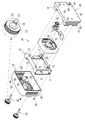
一例として図4および図5に示すように、冷却装置25は、一対の装置取付ネジ35、筐体36、保持枠37、ファン38、受電ユニット39、およびヒートシンク40を備える。筐体36は、保持枠37、ファン38、受電ユニット39、およびヒートシンク40を覆う。
As shown in FIGS. 4 and 5 as an example, the cooling device 25 includes a pair of device mounting screws 35, a housing 36, a holding frame 37, a fan 38, a power receiving unit 39, and a heat sink 40. Housing 36 covers holding frame 37 , fan 38 , power receiving unit 39 , and heat sink 40 .
装置取付ネジ35は取付機構26に含まれる。装置取付ネジ35は、細長い円柱状のネジ本体部50と、ネジ本体部50の一端に設けられ、ネジ本体部50よりも太径の円板状のネジ頭部51とを有する。ネジ本体部50は金属製、例えばステンレス製である。ネジ本体部50は、先端のネジ部52、中間の胴部53、および根元の首部54で構成される。ネジ部52は、被取付面17Aのネジ穴20に螺合される。胴部53は、ネジ部52および首部54よりも若干細径である。胴部53にはネジ山は切られていない。首部54には周状の溝55が形成されている。ネジ部52は、本開示の技術に係る「被嵌合部」の一例である。
The device mounting screw 35 is included in the mounting mechanism 26. The device mounting screw 35 has an elongated cylindrical screw body 50 and a disk-shaped screw head 51 provided at one end of the screw body 50 and having a larger diameter than the screw body 50 . The screw main body 50 is made of metal such as stainless steel. The screw body 50 is composed of a threaded portion 52 at the tip, a trunk portion 53 in the middle, and a neck portion 54 at the base. The screw portion 52 is screwed into the screw hole 20 of the mounting surface 17A. The barrel portion 53 has a slightly smaller diameter than the threaded portion 52 and the neck portion 54 . The body portion 53 is not threaded. A circumferential groove 55 is formed in the neck portion 54 . The threaded portion 52 is an example of a “fitted portion” according to the technology of the present disclosure.
ネジ頭部51は、高硬度かつ高耐熱性の樹脂製、例えばフェノール樹脂製である。ネジ頭部51は、冷却装置25の着脱時にユーザにより回転操作される。ネジ頭部51は、ユーザが指で掴みやすい大きさを有しており、その周面全体には滑り止め用の溝が形成されている。また、ネジ頭部51には、回転治具等を差し込むためのマイナス溝が形成されている。
The screw head 51 is made of a resin with high hardness and high heat resistance, such as phenol resin. The screw head 51 is rotated by the user when the cooling device 25 is attached or detached. The screw head 51 has a size that can be easily gripped by a user's fingers, and a non-slip groove is formed on the entire peripheral surface of the screw head 51 . Further, the screw head 51 is formed with a minus groove for inserting a rotary jig or the like.
筐体36には、装置取付ネジ35のネジ本体部50が挿通される一対の挿通穴60が形成されている。挿通穴60の周囲には、装置取付ネジ35のネジ頭部51が収容される凹部61が形成されている。このように、ネジ本体部50は筐体36の内部に配置され、ネジ頭部51は筐体36の外部に配置される(図7も参照)。
A pair of insertion holes 60 through which the screw body 50 of the device mounting screw 35 is inserted is formed in the housing 36 . A recess 61 is formed around the insertion hole 60 to accommodate the screw head 51 of the device mounting screw 35 . Thus, the screw body 50 is arranged inside the housing 36, and the screw head 51 is arranged outside the housing 36 (see also FIG. 7).
筐体36の四隅には、筐体取付ネジ62が挿通される挿通穴63が形成されている。筐体36の前面中央部には扇形状の吸気口64が放射状に複数形成されている。また、筐体36の両側面にはスリット状の吸気口65が複数形成されている。
Insertion holes 63 through which housing mounting screws 62 are inserted are formed in the four corners of the housing 36 . A plurality of fan-shaped intake ports 64 are radially formed in the central portion of the front surface of the housing 36 . A plurality of slit-shaped intake ports 65 are formed on both side surfaces of the housing 36 .
保持枠37は、ファン38および受電ユニット39を保持する。挿通穴60に対応する保持枠37の位置には、装置取付ネジ35のネジ本体部50が挿通される一対の挿通穴70が形成されている。また、挿通穴63に対応する保持枠37の位置には、ネジ穴71が形成されている。ネジ穴71には筐体取付ネジ62が螺合される。これにより筐体36と保持枠37とが一体化される。さらに、ネジ穴71よりも一回り内側の保持枠37の位置には、四つの挿通穴72が形成されている。挿通穴72には保持枠取付ネジ73が挿通される。
The holding frame 37 holds the fan 38 and the power receiving unit 39 . A pair of insertion holes 70 through which the screw body portion 50 of the device mounting screw 35 is inserted is formed at positions of the holding frame 37 corresponding to the insertion holes 60 . A screw hole 71 is formed at a position of the holding frame 37 corresponding to the insertion hole 63 . A housing mounting screw 62 is screwed into the screw hole 71 . As a result, the housing 36 and the holding frame 37 are integrated. Furthermore, four insertion holes 72 are formed at positions of the holding frame 37 one turn inside the screw holes 71 . A holding frame attachment screw 73 is inserted through the insertion hole 72 .
ファン38はヒートシンク40に冷却風を送る。より詳しくは、ファン38は、吸気口64および65から冷却装置25の内部に取り込まれる空気を吸い込んで、ヒートシンク40に向けて空気を吐き出す軸流ファンである。
The fan 38 sends cooling air to the heat sink 40. More specifically, the fan 38 is an axial fan that draws in air taken into the interior of the cooling device 25 through the air inlets 64 and 65 and discharges the air toward the heat sink 40 .
受電ユニット39は、受電コネクタ75とフレキシブル基板76とを有する。受電コネクタ75は、冷却装置25が被取付面17Aに取り付けられた際に、被取付面17Aの給電コネクタ21と接続する。受電コネクタ75は、給電コネクタ21を介して、ファン38の駆動電力をデジタルカメラ2から受電する。フレキシブル基板76は、受電コネクタ75に一端が接続され、ファン38に他端が接続される。フレキシブル基板76には、ファン38の駆動回路および電源回路が搭載されている。
The power receiving unit 39 has a power receiving connector 75 and a flexible substrate 76 . The power receiving connector 75 is connected to the power supply connector 21 on the mounting surface 17A when the cooling device 25 is mounted on the mounting surface 17A. The power receiving connector 75 receives driving power for the fan 38 from the digital camera 2 via the power feeding connector 21 . The flexible substrate 76 has one end connected to the power receiving connector 75 and the other end connected to the fan 38 . A drive circuit and a power supply circuit for the fan 38 are mounted on the flexible substrate 76 .
ファン38と対向するヒートシンク40の前面80には、全体的に放熱用の複数のフィン81が形成されている。フィン81は前後方向に立設され、左右方向に延び、かつ上下方向に略等間隔で並べられている。このフィン81が形成された前面80と反対側のヒートシンク40の背面82が、冷却装置25を取り付けた際に被取付面17Aと接する。
A plurality of fins 81 for heat dissipation are formed on the front surface 80 of the heat sink 40 facing the fan 38 . The fins 81 stand upright in the front-rear direction, extend in the left-right direction, and are arranged vertically at substantially equal intervals. A rear surface 82 of the heat sink 40 opposite to the front surface 80 on which the fins 81 are formed contacts the mounting surface 17A when the cooling device 25 is mounted.
挿通穴60および挿通穴70に対応するヒートシンク40の位置には、装置取付ネジ35のネジ本体部50が挿通される一対の挿通穴83が形成されている。挿通穴83は取付機構26に含まれる。挿通穴83は、本開示の技術に係る「フィンの形成領域」の一例であるヒートシンク40に設けられているので、取付機構26は「フィンの形成領域」と重畳している。また、挿通穴72に対応するヒートシンク40の位置には、ネジ穴84が形成されている。ネジ穴84には保持枠取付ネジ73が螺合される。これにより保持枠37とヒートシンク40、ひいてはファン38が一体化される。
A pair of through holes 83 through which the screw body portions 50 of the device mounting screws 35 are inserted are formed at positions of the heat sink 40 corresponding to the through holes 60 and 70 . Insertion hole 83 is included in attachment mechanism 26 . Since the insertion hole 83 is provided in the heat sink 40, which is an example of the "fin formation area" according to the technology of the present disclosure, the attachment mechanism 26 overlaps with the "fin formation area." A screw hole 84 is formed at a position of the heat sink 40 corresponding to the insertion hole 72 . A holding frame mounting screw 73 is screwed into the screw hole 84 . As a result, the holding frame 37, the heat sink 40, and the fan 38 are integrated.
ヒートシンク40の左端には、平面視でU字状をしたコネクタ配置部85が形成されている。コネクタ配置部85は、ヒートシンク40の左端の一部を切欠くことで設けられる。コネクタ配置部85には受電コネクタ75が配置される(図9参照)。
At the left end of the heat sink 40, a U-shaped connector placement portion 85 is formed in plan view. The connector placement portion 85 is provided by cutting out a portion of the left end of the heat sink 40 . A power receiving connector 75 is arranged in the connector arrangement portion 85 (see FIG. 9).
一例として図6に示すように、取付機構26に含まれる装置取付ネジ35および挿通穴83は、ファン38を挟んで左右の対向する位置に設けられている。また、フィン81は、高さH1のフィン811と、高さH2Aのフィン812Aと、高さH3のフィン813と、上下端に形成されたフィン814とを含む。挿通穴83は、隣り合う2つのフィン812Aの間に設けられている。フィン812Aの高さH2Aは、フィン811の高さH1よりも低い(H2A<H1)。
As an example, as shown in FIG. 6, the device mounting screws 35 and the insertion holes 83 included in the mounting mechanism 26 are provided at opposite positions on the left and right with the fan 38 interposed therebetween. The fin 81 includes a fin 811 of height H1, a fin 812A of height H2A, a fin 813 of height H3, and fins 814 formed at the upper and lower ends. The insertion hole 83 is provided between two adjacent fins 812A. The height H2A of the fin 812A is lower than the height H1 of the fin 811 (H2A<H1).
平面視において、フィン813はファン38と重畳する。フィン813の高さH3は、フィン811の高さH1よりも低い(H3<H1)。
The fins 813 overlap the fan 38 in plan view. The height H3 of the fin 813 is lower than the height H1 of the fin 811 (H3<H1).
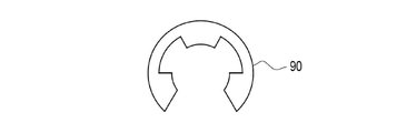
一例として図7に示すように、装置取付ネジ35の首部54の溝55には、一例として図8に示すE型止め輪(Eリングとも呼ばれる)90が嵌め込まれる。首部54は、筐体36とフィン812Aとの間に位置している。このため、E型止め輪90は、筐体36とフィン812Aとの間に設けられる。E型止め輪90の径は、挿通穴70よりも小さいが、挿通穴60よりも大きい。このため、装置取付ネジ35は、挿通穴60と挿通穴70のストローク分、前後に移動することが可能である。また、装置取付ネジ35のネジ本体部50は、E型止め輪90によって、挿通穴60、ひいては筐体36からの脱落が防止される。なお、装置取付ネジ35の脱落を防止する部材としては、首部54に形成された貫通穴に突き込まれるピン等でもよい。
As shown in FIG. 7 as an example, an E-shaped retaining ring (also called an E-ring) 90 shown in FIG. 8 is fitted into the groove 55 of the neck 54 of the device mounting screw 35 . Neck 54 is located between housing 36 and fin 812A. Therefore, the E-shaped retaining ring 90 is provided between the housing 36 and the fins 812A. The diameter of the E-shaped retaining ring 90 is smaller than the through hole 70 but larger than the through hole 60 . Therefore, the device mounting screw 35 can move back and forth by the stroke of the insertion hole 60 and the insertion hole 70 . Further, the E-shaped retaining ring 90 prevents the screw main body 50 of the device mounting screw 35 from falling out of the insertion hole 60 and thus the housing 36 . A pin or the like inserted into a through hole formed in the neck portion 54 may be used as the member for preventing the device mounting screw 35 from coming off.
一例として図9に示すように、デジタルカメラ2の熱源95は、カメラボディ10の略中心に位置している。熱源95は、例えば、撮像素子12、撮像素子12の駆動回路、電源回路、およびCPU13を含む。対して冷却装置25は、カメラボディ10の中心から左側にずれた位置に取り付けられる。このため、冷却装置25から見た場合、熱源95は右側にずれている。
As an example, as shown in FIG. 9, the heat source 95 of the digital camera 2 is positioned substantially at the center of the camera body 10 . The heat source 95 includes, for example, the imaging element 12, a drive circuit for the imaging element 12, a power supply circuit, and the CPU 13. On the other hand, the cooling device 25 is attached at a position shifted to the left from the center of the camera body 10 . Therefore, when viewed from the cooling device 25, the heat source 95 is shifted to the right.
図6および図9において、ヒートシンク40は、ファン38に対して右側に配されたフィン81の第1形成領域96と、ファン38に対して左側に配されたフィン81の第2形成領域97とを有する。熱源95の大部分は右側の第1形成領域96にある。言い換えれば、熱源95は、第2形成領域97よりも第1形成領域96に多く重畳している。対して、ヒートシンク40のコネクタ配置部85、ひいては受電コネクタ75は左側の第2形成領域97にある。第1形成領域96の面積は、コネクタ配置部85が設けられていない分、第2形成領域97の面積S2よりも大きい(S2<S1)。また、図9において、コネクタ配置部85、ひいては受電コネクタ75は、ヒートシンク40の中心Cよりも下側に配置されている。ここで、ファン38に対して右側は、本開示の技術に係る「第1側」の一例である。また、ファン38に対して左側は、本開示の技術に係る「第2側」の一例である。なお、熱源95は、撮像素子12およびCPU13のうちの少なくともいずれか1つを含んでいればよい。また、冷却装置25は、デジタルカメラ2の内部において背面17に近い熱源95をより効率的に冷却することを目的としているため、図1に基づけば、熱源95は、撮像素子12よりも背面17に近いCPU13であることが好ましい。
6 and 9, the heat sink 40 has a first formation region 96 for the fins 81 arranged on the right side of the fan 38 and a second formation region 97 for the fins 81 arranged on the left side of the fan 38. have Most of the heat source 95 is in the first forming area 96 on the right. In other words, the heat source 95 overlaps the first formation region 96 more than the second formation region 97 . On the other hand, the connector placement portion 85 of the heat sink 40 and, by extension, the power receiving connector 75 are located in the second formation area 97 on the left side. The area of the first formation region 96 is larger than the area S2 of the second formation region 97 (S2<S1) because the connector placement portion 85 is not provided. In addition, in FIG. 9 , the connector placement portion 85 and thus the power receiving connector 75 are placed below the center C of the heat sink 40 . Here, the right side with respect to the fan 38 is an example of the "first side" according to the technology of the present disclosure. Also, the left side of the fan 38 is an example of the "second side" according to the technology of the present disclosure. Note that the heat source 95 may include at least one of the image sensor 12 and the CPU 13 . Further, the cooling device 25 is intended to more efficiently cool the heat source 95 near the back surface 17 inside the digital camera 2 , so based on FIG. It is preferable that the CPU 13 is close to
次に、上記構成による作用を説明する。ユーザは、画像を撮影する際等に、移動式モニタ18を背面17から移動させ、移動式モニタ18を所望の位置および角度とする。ユーザは、例えばモードダイヤル15で動画像撮影モードを選択して動画像撮影(例えば解像度4K相当の画質で秒間120コマ(4K/120p)の動画像撮影)を行う場合等、特に熱源95の発熱が懸念される場合に、冷却装置25を被取付面17Aに取り付ける。この際、ユーザは、被取付面17Aの給電コネクタ21に受電コネクタ75を接続し、かつ、被取付面17Aのネジ穴20に装置取付ネジ35のネジ部52を螺合させる。
Next, the action of the above configuration will be explained. When the user takes an image or the like, the user moves the mobile monitor 18 from the rear surface 17 to the desired position and angle. For example, when the user selects a moving image shooting mode with the mode dial 15 and shoots a moving image (for example, shooting a moving image at 120 frames per second (4K/120p) with an image quality equivalent to 4K resolution), the heat source 95 especially generates heat. is concerned, the cooling device 25 is attached to the attachment surface 17A. At this time, the user connects the power receiving connector 75 to the power supply connector 21 of the mounting surface 17A, and screws the screw portion 52 of the device mounting screw 35 into the screw hole 20 of the mounting surface 17A.
ヒートシンク40の背面82は被取付面17Aに接する。このため、熱源95で発生した熱は、被取付面17Aからヒートシンク40に伝達され、ヒートシンク40のフィン81により放熱される。また、受電コネクタ75を介して駆動電力が供給され、ファン38が動作される。これによりファン38からヒートシンク40に冷却風が送られ、ヒートシンク40に伝達された熱が冷却される。
The back surface 82 of the heat sink 40 is in contact with the mounting surface 17A. Therefore, the heat generated by the heat source 95 is transmitted from the mounting surface 17A to the heat sink 40 and radiated by the fins 81 of the heat sink 40. As shown in FIG. Driving power is supplied through the power receiving connector 75 to operate the fan 38 . As a result, cooling air is sent from the fan 38 to the heat sink 40, and the heat transferred to the heat sink 40 is cooled.
以上説明したように、冷却装置25は、放熱用の複数のフィン81が形成されたヒートシンク40と、ヒートシンク40をデジタルカメラ2の被取付面17Aに着脱可能に取り付けるための取付機構26とを備える。図6で示したように、取付機構26の一部である挿通穴83は、フィン81の形成領域に重畳している。このため、取付機構26によってフィン81が犠牲になることがない。したがって、必要なときにデジタルカメラ2を冷却することが可能で、かつ冷却性能の低下を抑制することが可能となる。
As described above, the cooling device 25 includes the heat sink 40 formed with a plurality of heat radiation fins 81 and the attachment mechanism 26 for detachably attaching the heat sink 40 to the attachment surface 17A of the digital camera 2. . As shown in FIG. 6 , the insertion holes 83 that are part of the mounting mechanism 26 overlap the areas where the fins 81 are formed. Therefore, the attachment mechanism 26 does not sacrifice the fins 81 . Therefore, it is possible to cool the digital camera 2 when necessary, and to prevent deterioration of the cooling performance.
図4および図5で示したように、取付機構26は、フィン81の形成領域に設けられ、装置取付ネジ35が挿通される挿通穴83を含む。このため、取付機構26をシンプルな構造とすることができる。
As shown in FIGS. 4 and 5, the mounting mechanism 26 includes insertion holes 83 provided in the formation area of the fins 81 and through which the device mounting screws 35 are inserted. Therefore, the mounting mechanism 26 can have a simple structure.
図6で示したように、挿通穴83は、隣り合う2つのフィン812Aの間に設けられている。このため、挿通穴83を容易に形成することができる。
As shown in FIG. 6, the insertion hole 83 is provided between two adjacent fins 812A. Therefore, the insertion hole 83 can be easily formed.
図4で示したように、装置取付ネジ35は、挿通穴83に挿通されるネジ本体部50と、ネジ本体部50の一端に設けられ、ヒートシンク40(冷却装置25)の着脱時にユーザにより操作されるネジ頭部51とを有する。このため、ヒートシンク40(冷却装置25)を容易に着脱することができる。
As shown in FIG. 4, the device mounting screw 35 is provided with a screw body portion 50 that is inserted through the insertion hole 83 and one end of the screw body portion 50, and is operated by the user when the heat sink 40 (cooling device 25) is attached or detached. and a screw head 51 that is Therefore, the heat sink 40 (cooling device 25) can be easily attached and detached.
冷却装置25はヒートシンク40を覆う筐体36を備える。また、図7で示したように、ネジ頭部51は筐体36の外部に配置され、ネジ本体部50は筐体36の内部に配置される。そして、ネジ本体部50とネジ頭部51との境界部である首部54には、筐体36からの装置取付ネジ35の脱落を防止する脱落防止部材としてのE型止め輪90が取り付けられる。このため、筐体36からの装置取付ネジ35の脱落を防止することができる。なお、筐体36は、ヒートシンク40だけでなく保持枠37、ファン38、および受電ユニット39も覆っているが、ヒートシンク40を覆っていることに変わりはない。
The cooling device 25 has a housing 36 that covers the heat sink 40 . Further, as shown in FIG. 7, the screw head 51 is arranged outside the housing 36 and the screw main body 50 is arranged inside the housing 36 . An E-shaped retaining ring 90 is attached to the neck portion 54 which is the boundary portion between the screw main body portion 50 and the screw head portion 51 as a fall prevention member for preventing the device mounting screw 35 from falling out of the housing 36 . Therefore, it is possible to prevent the device mounting screws 35 from coming off the housing 36 . Although the housing 36 covers not only the heat sink 40 but also the holding frame 37 , the fan 38 , and the power receiving unit 39 , it still covers the heat sink 40 .
図6で示したように、フィン81は、フィン811と、フィン811よりも高さが低いフィン812Aとを含む。フィン812Aは、挿通穴83と隣接するフィンである。このため、フィン812Aの前面80側にスペースを確保することができる。本例においては、このスペースに首部54が配置される。したがって、首部54の溝55にE型止め輪90を嵌め込んで、装置取付ネジ35の抜け止めとすることが可能となる。
As shown in FIG. 6, the fins 81 include fins 811 and fins 812A lower in height than the fins 811. Fin 812A is a fin adjacent to insertion hole 83 . Therefore, a space can be secured on the front surface 80 side of the fin 812A. In this example, the neck 54 is arranged in this space. Therefore, by fitting the E-shaped snap ring 90 into the groove 55 of the neck portion 54, it is possible to prevent the device mounting screw 35 from coming off.
装置取付ネジ35は、ネジ本体部50が金属製である。このため、ヒートシンク40のフィン81と同様に、ネジ本体部50を放熱部材として働かせることができる。一方で、装置取付ネジ35は、ネジ頭部51が高耐熱性の樹脂製である。このため、ネジ頭部51にはネジ本体部50からの熱は伝わらない。したがって、ネジ頭部51を把持するユーザの指を熱から保護することができる。
The device mounting screw 35 has a screw main body 50 made of metal. Therefore, like the fins 81 of the heat sink 40, the screw main body 50 can function as a heat dissipation member. On the other hand, the device mounting screw 35 has a screw head 51 made of a highly heat-resistant resin. Therefore, the heat from the screw body portion 50 is not transmitted to the screw head portion 51 . Therefore, the user's fingers holding the screw head 51 can be protected from heat.
冷却装置25は、ヒートシンク40に冷却風を送るファン38を備える。図6で示したように、一対の取付機構26は、ファン38を挟む位置に設けられている。このため、冷却装置25を被取付面17Aに取り付けた際の安定感が増す。ファン38の振動による冷却装置25のがたつきを抑えることができる。
The cooling device 25 has a fan 38 that sends cooling air to the heat sink 40 . As shown in FIG. 6, the pair of mounting mechanisms 26 are provided at positions sandwiching the fan 38 . Therefore, the feeling of stability when the cooling device 25 is attached to the attachment surface 17A is increased. Rattling of the cooling device 25 due to vibration of the fan 38 can be suppressed.
図6で示したように、ファン38は、フィン81の形成領域に取り付けられる。フィン81は、フィン811と、フィン811よりも高さが低いフィン813とを含む。平面視において、フィン813はファン38と重畳する。このため、フィン813の前面80側にファン38用のスペースを確保することができる。冷却装置25のコンパクト化に寄与することができる。
As shown in FIG. 6, the fan 38 is attached to the area where the fins 81 are formed. The fins 81 include fins 811 and fins 813 lower in height than the fins 811 . The fins 813 overlap the fan 38 in plan view. Therefore, a space for the fan 38 can be secured on the front surface 80 side of the fins 813 . This can contribute to making the cooling device 25 compact.
図3で示したように、デジタルカメラシステム30は、移動式モニタ18を備えたデジタルカメラ2と、デジタルカメラ2で発生した熱を冷却する冷却装置25とを備える。デジタルカメラ2では、最近、特に動画像撮影時の発熱が問題になっている。このため、動画像撮影時等の必要なときに、デジタルカメラ2で発生した熱を冷却装置25で効率的に冷却することができる。
As shown in FIG. 3, the digital camera system 30 includes a digital camera 2 equipped with a mobile monitor 18 and a cooling device 25 for cooling the heat generated by the digital camera 2. In recent years, the digital camera 2 has a problem of heat generation, especially during moving image shooting. Therefore, the heat generated by the digital camera 2 can be efficiently cooled by the cooling device 25 when necessary, such as when photographing a moving image.
デジタルカメラ2は、移動式モニタ18と、被取付面17Aにあるネジ穴20とを備える。冷却装置25は、デジタルカメラ2に着脱可能に取り付けるための取付機構26を備える。取付機構26は、移動式モニタが被取付面17Aに対向する位置から移動することによって露呈するネジ穴20に取り付けられる。被取付面17Aは、普段は移動式モニタ18によって覆われている。このため、ネジ穴20も普段は移動式モニタ18によって隠れている。したがって、常にネジ穴20がむき出しの状態のデジタルカメラと比べて見栄えがよい。また、ネジ穴20にゴミ等の異物が入る機会が減るため、常にネジ穴20がむき出しの状態のデジタルカメラと比べて故障のおそれが少なく、メンテナンス性もよい。
The digital camera 2 includes a mobile monitor 18 and screw holes 20 on the mounting surface 17A. The cooling device 25 has an attachment mechanism 26 for detachably attaching to the digital camera 2 . The attachment mechanism 26 is attached to the screw hole 20 exposed by moving the mobile monitor from the position facing the attachment surface 17A. The mounting surface 17A is normally covered with a mobile monitor 18. As shown in FIG. Therefore, the screw holes 20 are also normally hidden by the mobile monitor 18 . Therefore, it looks better than a digital camera in which the screw holes 20 are always exposed. In addition, since there is less chance of foreign matter such as dust entering the screw hole 20, there is less risk of failure compared to a digital camera in which the screw hole 20 is always exposed, and maintainability is good.
デジタルカメラ2は嵌合部であるネジ穴20を含み、冷却装置25の取付機構26は、ネジ穴20に嵌合する被嵌合部であるネジ部52を含む。このため、シンプルな構造でデジタルカメラ2に冷却装置25を着脱することができる。
The digital camera 2 includes a threaded hole 20 that is a fitting portion, and the mounting mechanism 26 of the cooling device 25 includes a threaded portion 52 that is a fitted portion that fits into the threaded hole 20 . Therefore, the cooling device 25 can be attached to and detached from the digital camera 2 with a simple structure.
図2で示したように、移動式モニタ18はバリアングル方式のモニタである。このため、移動式モニタを背面から後方に引き出して上下方向に回転させるチルト方式と比べて被取付面17Aの面積が広く、その分冷却装置25のヒートシンク40との接触面を広く確保することができる。したがって、より冷却効率を高めることができる。
As shown in FIG. 2, the mobile monitor 18 is a vari-angle monitor. Therefore, compared to the tilt system in which the mobile monitor is pulled out rearward from the rear surface and rotated in the vertical direction, the mounting surface 17A has a larger area, and the contact surface of the cooling device 25 with the heat sink 40 can be secured correspondingly wider. can. Therefore, it is possible to further improve the cooling efficiency.
図5で示したように、ヒートシンク40はコネクタ配置部85を有する。コネクタ配置部85には、ファン38の駆動電力をデジタルカメラ2から受電する受電コネクタ75が配置される。図9で示したように、デジタルカメラ2の熱源95は第1形成領域96の側の右側にあり、受電コネクタ75は第2形成領域97の側の左側にある。そして、第1形成領域96の面積S1は、第2形成領域の面積S2よりも大きい。また、受電コネクタ75は、ヒートシンク40の中心Cよりも下側に配置されている。
As shown in FIG. 5, the heat sink 40 has a connector placement portion 85. A power receiving connector 75 for receiving power for driving the fan 38 from the digital camera 2 is arranged in the connector arrangement portion 85 . As shown in FIG. 9, the heat source 95 of the digital camera 2 is on the right side of the first formation area 96 side, and the power receiving connector 75 is on the left side of the second formation area 97 side. The area S1 of the first formation region 96 is larger than the area S2 of the second formation region. Also, the power receiving connector 75 is arranged below the center C of the heat sink 40 .
コネクタ配置部85が形成された部分は、フィン81がないので冷却性能が劣る。このため、冷却が必要な熱源95と同じ第1形成領域96にコネクタ配置部85を形成した場合、冷却効率が低下する懸念がある。しかし、本例では、第1形成領域96とは反対側の第2形成領域97にコネクタ配置部85を形成して受電コネクタ75を配置しているので、冷却効率が低下する懸念は少ない。
The part where the connector placement part 85 is formed has no fins 81, so the cooling performance is inferior. Therefore, if the connector placement portion 85 is formed in the same first formation region 96 as the heat source 95 that requires cooling, there is a concern that the cooling efficiency will decrease. However, in this example, since the connector placement portion 85 is formed in the second formation region 97 opposite to the first formation region 96 to place the power receiving connector 75, there is little concern that the cooling efficiency will be lowered.
また、熱は相対的にヒートシンク40の上部に籠りやすい。このため、ヒートシンク40の中心よりも上側にコネクタ配置部85を形成した場合も、冷却効率が低下する懸念がある。しかし、本例では、ヒートシンク40の中心Cよりも下側にコネクタ配置部85を形成して受電コネクタ75を配置しているので、冷却効率が低下する懸念は少ない。
Also, heat is relatively likely to stay in the upper part of the heat sink 40 . Therefore, even if the connector placement portion 85 is formed above the center of the heat sink 40, there is a concern that the cooling efficiency will decrease. However, in this example, since the connector arrangement portion 85 is formed below the center C of the heat sink 40 and the power receiving connector 75 is arranged, there is little concern that the cooling efficiency will decrease.
電子機器は、動画像を撮像する撮像素子12を有するデジタルカメラ2であり、熱源95は、撮像素子12、および動画像の処理を実行するCPU13である。このため、特に熱源95の発熱が懸念される動画像撮影の際に、冷却装置25で効率的に冷却することができる。
The electronic device is the digital camera 2 having the image sensor 12 that captures moving images, and the heat source 95 is the image sensor 12 and the CPU 13 that processes the moving images. Therefore, the cooling device 25 can efficiently cool the moving image when the heat source 95 is particularly concerned about heat generation.
以下の説明では、上記第1実施形態で説明した部材および部位と同じ部材および部位には、上記第1実施形態と同じ符号を付して説明を省略する。
In the following description, members and parts that are the same as those described in the first embodiment are denoted by the same reference numerals as in the first embodiment, and descriptions thereof are omitted.
[第2実施形態]
上記第1実施形態では、隣り合う2つのフィン812Aの間に挿通穴83を設けているが、これに限らない。一例として図10および図11に示すヒートシンク100のように、フィン812Bを貫通して挿通穴83を設けてもよい。 [Second embodiment]
Although theinsertion hole 83 is provided between the two adjacent fins 812A in the first embodiment, the configuration is not limited to this. As an example, like the heat sink 100 shown in FIGS. 10 and 11, the insertion holes 83 may be provided through the fins 812B.
上記第1実施形態では、隣り合う2つのフィン812Aの間に挿通穴83を設けているが、これに限らない。一例として図10および図11に示すヒートシンク100のように、フィン812Bを貫通して挿通穴83を設けてもよい。 [Second embodiment]
Although the
図11に示すように、フィン812Bの高さH2Bは、フィン811の高さH1よりも低い(H2B<H1)。
As shown in FIG. 11, the height H2B of the fin 812B is lower than the height H1 of the fin 811 (H2B<H1).
このように、第2実施形態では、挿通穴83は、フィン812Bを貫通している。このため、フィン81の間には装置取付ネジ35のネジ本体部50は配置されない。したがって、ネジ本体部50によってフィン812Aの間の風の通りが悪くなる上記第1実施形態と比べて、風の通りをよくすることができる。
Thus, in the second embodiment, the insertion holes 83 pass through the fins 812B. Therefore, the screw body portion 50 of the device mounting screw 35 is not arranged between the fins 81 . Therefore, it is possible to improve the passage of air compared to the above-described first embodiment in which passage of air between the fins 812A is poor due to the screw body portion 50 .
なお、フィン812Bにおいて、挿通穴83が形成される部分の上下方向の幅を、他の部分よりも太くしてもよい。
In addition, in the fin 812B, the width in the vertical direction of the portion where the insertion hole 83 is formed may be made wider than the other portions.
[第3実施形態]
一例として図12に示すように、デジタルカメラ110は、被取付面17Aに凹部111が形成されている。凹部111は、移動式モニタ18が中途半端な左右方向の開き角度で上下方向に回転された場合に、移動式モニタ18の角部が被取付面17Aに当たらないようにするための段差である。凹部111は、本開示の技術に係る「段差」の一例である。 [Third Embodiment]
As an example, as shown in FIG. 12, adigital camera 110 has a concave portion 111 formed in a mounting surface 17A. The concave portion 111 is a step for preventing the corner of the movable monitor 18 from coming into contact with the mounting surface 17A when the movable monitor 18 is rotated in the vertical direction at an incomplete horizontal opening angle. . The concave portion 111 is an example of a “step” according to the technology of the present disclosure.
一例として図12に示すように、デジタルカメラ110は、被取付面17Aに凹部111が形成されている。凹部111は、移動式モニタ18が中途半端な左右方向の開き角度で上下方向に回転された場合に、移動式モニタ18の角部が被取付面17Aに当たらないようにするための段差である。凹部111は、本開示の技術に係る「段差」の一例である。 [Third Embodiment]
As an example, as shown in FIG. 12, a
冷却装置115は、デジタルカメラ110とでデジタルカメラシステム120を構成する。冷却装置115は、基本的な構成は上記第1実施形態の冷却装置25と同じであるが、被取付面17Aの凹部111に密着させるための弾性シート116が貼り付けられている点で冷却装置25と異なる。弾性シート116は、その名の通り弾性を有し、かつ比較的高い熱伝導性を有する。弾性シート116は、例えばグラファイトシートである。
The cooling device 115 constitutes a digital camera system 120 together with the digital camera 110 . The cooling device 115 has the same basic configuration as the cooling device 25 of the first embodiment, except that an elastic sheet 116 is adhered for close contact with the recess 111 of the mounting surface 17A. 25 different. The elastic sheet 116 has elasticity, as its name suggests, and relatively high thermal conductivity. The elastic sheet 116 is, for example, a graphite sheet.
一例として図13に示すように、弾性シート116は、被取付面17Aと接するヒートシンク40の背面82に貼り付けられている。弾性シート116は背面82を略覆っているが、わずかに一部を露呈させている。すなわち弾性シート116は、挿通穴83に合わせて円形状にくり抜かれた穴121、および受電コネクタ75に合わせて矩形状に切りかかれた角部122を有している。挿通穴83は取付機構26に含まれるため、弾性シート116は、穴121によって、取付機構26の部分には設けられていない。また、弾性シート116は、角部122によって、受電コネクタ75の部分には設けられていない。
As shown in FIG. 13 as an example, the elastic sheet 116 is attached to the back surface 82 of the heat sink 40 that contacts the mounting surface 17A. The elastic sheet 116 substantially covers the rear surface 82, but slightly exposes a portion thereof. That is, the elastic sheet 116 has a circular hole 121 cut to fit the insertion hole 83 and a rectangular corner 122 cut to fit the power receiving connector 75 . Since the insertion hole 83 is included in the attachment mechanism 26 , the elastic sheet 116 is not provided in the attachment mechanism 26 portion due to the hole 121 . Also, the elastic sheet 116 is not provided at the power receiving connector 75 due to the corner portion 122 .
このように、第3実施形態の冷却装置115は、被取付面17Aへの取付面であるヒートシンク40の背面82に設けられ、被取付面17Aに密着させるための弾性シート116を備える。弾性シート116は、被取付面17Aの凹部111に密着する。このため、被取付面17Aに凹部111等の段差がある場合においても、被取付面17Aへのヒートシンク40の密着性を高めることができ、より多くの熱を被取付面17Aからヒートシンク40に伝達させることができる。
Thus, the cooling device 115 of the third embodiment is provided on the rear surface 82 of the heat sink 40, which is the mounting surface to the mounting surface 17A, and includes the elastic sheet 116 for closely contacting the mounting surface 17A. The elastic sheet 116 is in close contact with the recess 111 of the mounting surface 17A. Therefore, even if the mounting surface 17A has a step such as the concave portion 111, the adhesion of the heat sink 40 to the mounting surface 17A can be enhanced, and more heat can be transferred from the mounting surface 17A to the heat sink 40. can be made
弾性シート116は、取付機構26の部分には設けられていない。このため、弾性シート116によって冷却装置115の被取付面17Aへの取り付けが阻害されることがない。また、弾性シート116は、受電コネクタ75の部分には設けられていない。このため、弾性シート116によってファン38への給電が阻害されることがない。
The elastic sheet 116 is not provided in the mounting mechanism 26 portion. Therefore, the elastic sheet 116 does not hinder the attachment of the cooling device 115 to the attachment surface 17A. Also, the elastic sheet 116 is not provided at the power receiving connector 75 portion. Therefore, the elastic sheet 116 does not hinder the power supply to the fan 38 .
なお、一例として図14に示す冷却装置125のように、挿通穴83および受電コネクタ75よりも内側に収まる大きさの弾性シート126を用いてもよい。こうすることでも、弾性シート126は、取付機構26および受電コネクタ75の部分には設けられていないことになる。
As an example, as in a cooling device 125 shown in FIG. 14, an elastic sheet 126 having a size that fits inside the insertion hole 83 and the power receiving connector 75 may be used. By doing so, the elastic sheet 126 is also not provided in the mounting mechanism 26 and the power receiving connector 75 .
弾性シート116または126を貼り付ける代わりに、ヒートシンク40の背面82に、凹部111に対応した凸部を形成してもよい。ただし、この方法では背面82を加工する手間が掛かるため、弾性シート116または126を貼り付ける方法のほうが好ましい。
Instead of attaching the elastic sheet 116 or 126, a convex portion corresponding to the concave portion 111 may be formed on the rear surface 82 of the heat sink 40. However, since this method requires time and effort to process the back surface 82, the method of attaching the elastic sheet 116 or 126 is preferable.
[第4実施形態]
一例として図15および図16に示すように、第4実施形態の冷却装置130は、受電コネクタ75に着脱可能に取り付けられるコネクタカバー131を備える。コネクタカバー131は、冷却装置130の非使用時に受電コネクタ75に被せられ、受電コネクタ75を覆う。 [Fourth Embodiment]
As shown in FIGS. 15 and 16 as an example, thecooling device 130 of the fourth embodiment includes a connector cover 131 detachably attached to the power receiving connector 75 . The connector cover 131 is put on the power receiving connector 75 to cover the power receiving connector 75 when the cooling device 130 is not in use.
一例として図15および図16に示すように、第4実施形態の冷却装置130は、受電コネクタ75に着脱可能に取り付けられるコネクタカバー131を備える。コネクタカバー131は、冷却装置130の非使用時に受電コネクタ75に被せられ、受電コネクタ75を覆う。 [Fourth Embodiment]
As shown in FIGS. 15 and 16 as an example, the
受電コネクタ75と筐体36との間であって、筐体36の受電コネクタ75と対面する部分には、収容部132が設けられている。収容部132は、冷却装置130の使用時に受電コネクタ75から取り外されたコネクタカバー131を収容する。収容部132には、収容された受電コネクタ75を保持する保持機構(図示省略)が設けられている。保持機構は、例えば、バネの付勢によりコネクタカバー131を収容部132の壁面に押し付けるものである。あるいは、保持機構は、収容部132の開口を開閉するシャッタである。保持機構は、磁力によりコネクタカバー131を吸着保持するものであってもよい。収容部132からコネクタカバー131を取り出す際には、ボタン操作等で保持機構による保持が解除される。
A housing portion 132 is provided in a portion of the housing 36 facing the power receiving connector 75 and between the power receiving connector 75 and the housing 36 . Accommodating portion 132 accommodates connector cover 131 removed from power receiving connector 75 when cooling device 130 is used. A holding mechanism (not shown) that holds the housed power receiving connector 75 is provided in the housing portion 132 . The holding mechanism presses the connector cover 131 against the wall surface of the housing portion 132 by the force of a spring, for example. Alternatively, the holding mechanism is a shutter that opens and closes the opening of the housing portion 132 . The holding mechanism may attract and hold the connector cover 131 by magnetic force. When the connector cover 131 is taken out from the accommodating portion 132, the holding by the holding mechanism is released by operating a button or the like.
このように、第4実施形態の冷却装置130は、非使用時に受電コネクタ75を覆うコネクタカバー131と、使用時に受電コネクタ75から取り外されたコネクタカバー131を収容する収容部132とを備える。コネクタカバー131によって、非使用時に受電コネクタ75にゴミ等の異物が入る機会が減るため、故障のおそれを低減することができ、メンテナンス性の向上にも寄与することができる。また、収容部132があることで、受電コネクタ75から取り外したコネクタカバー131の行き場が確保されるので、コネクタカバー131の紛失を防止することができる。
Thus, the cooling device 130 of the fourth embodiment includes the connector cover 131 that covers the power receiving connector 75 when not in use, and the housing portion 132 that houses the connector cover 131 removed from the power receiving connector 75 when in use. Since the connector cover 131 reduces the chances of dust or other foreign matter entering the power receiving connector 75 when not in use, it is possible to reduce the risk of failure and contribute to improved maintainability. In addition, since the accommodation portion 132 provides a place for the connector cover 131 removed from the power receiving connector 75 to go, loss of the connector cover 131 can be prevented.
収容部132は、受電コネクタ75と筐体36との間に設けられている。このため、非使用時にコネクタカバー131を受電コネクタ75に被せる際、および使用時に受電コネクタ75から取り外したコネクタカバー131を収容する際に、アクセスがしやすい。
The accommodation portion 132 is provided between the power receiving connector 75 and the housing 36 . Therefore, access is easy when covering the power receiving connector 75 with the connector cover 131 when not in use, and when housing the connector cover 131 removed from the power receiving connector 75 when in use.
[第5実施形態]
一例として図17に示すように、冷却装置135は、側部136に台形円柱状の複数のゴムクッション137が取り付けられている。側部136は、移動式モニタ18が被取付面17Aと対向する位置から移動した場合に、移動式モニタ18と対向する部位である。ゴムクッション137は、本開示の技術に係る「保護部材」および「凸状部材」の一例である。このゴムクッション137があることによって、移動式モニタ18を側部136に誤ってぶつけても、移動式モニタ18に傷がつくことはない。したがって、移動式モニタ18を保護することができる。 [Fifth embodiment]
As an example, as shown in FIG. 17 , thecooling device 135 has a plurality of trapezoidal cylindrical rubber cushions 137 attached to the side portion 136 . The side portion 136 is a portion facing the mobile monitor 18 when the mobile monitor 18 moves from the position facing the mounting surface 17A. The rubber cushion 137 is an example of a “protective member” and a “convex member” according to the technology of the present disclosure. Due to the presence of this rubber cushion 137, even if the mobile monitor 18 is accidentally hit against the side portion 136, the mobile monitor 18 will not be damaged. Therefore, the mobile monitor 18 can be protected.
一例として図17に示すように、冷却装置135は、側部136に台形円柱状の複数のゴムクッション137が取り付けられている。側部136は、移動式モニタ18が被取付面17Aと対向する位置から移動した場合に、移動式モニタ18と対向する部位である。ゴムクッション137は、本開示の技術に係る「保護部材」および「凸状部材」の一例である。このゴムクッション137があることによって、移動式モニタ18を側部136に誤ってぶつけても、移動式モニタ18に傷がつくことはない。したがって、移動式モニタ18を保護することができる。 [Fifth embodiment]
As an example, as shown in FIG. 17 , the
なお、一例として図18に示す冷却装置140のように、ゴムクッション137に代えて、側部141を覆うゴムカバー142を採用してもよい。ゴムカバー142は、本開示の技術に係る「保護部材」および「被覆部材」の一例である。ゴムカバー142によれば、ゴムクッション137と比べて外側への出っ張り量が減るので、見栄えをよくすることができる。
As an example, like a cooling device 140 shown in FIG. 18, a rubber cover 142 that covers the side portion 141 may be employed instead of the rubber cushion 137 . The rubber cover 142 is an example of a “protective member” and a “coating member” according to the technology of the present disclosure. According to the rubber cover 142, compared with the rubber cushion 137, the amount of protrusion to the outside is reduced, so the appearance can be improved.
上記各実施形態では、取付機構26として装置取付ネジ35を例示しているが、これに限らない。一例として図19に示す装置取付ピン150を用いてもよい。装置取付ピン150はいわゆる回転式ロックピンであり、ピン本体部151と、ピン本体部151の一端に設けられた回転ノブ152とを有する。ピン本体部151は金属製であり、回転ノブ152は高硬度かつ高耐熱性の樹脂製である。回転ノブ152は、ヒートシンク40の着脱時にユーザにより回転操作される。ピン本体部151の先端部153には、一対の円柱状の突起154が対向する位置に形成されている。突起154(ピン本体部151)は、回転ノブ152の回転操作に連動して90°回転する。先端部153は、本開示の技術に係る「被嵌合部」の一例である。
Although the device mounting screw 35 is exemplified as the mounting mechanism 26 in each of the above embodiments, it is not limited to this. As an example, a device mounting pin 150 shown in FIG. 19 may be used. The device mounting pin 150 is a so-called rotary lock pin, and has a pin body portion 151 and a rotary knob 152 provided at one end of the pin body portion 151 . The pin main body 151 is made of metal, and the rotary knob 152 is made of resin with high hardness and high heat resistance. The rotation knob 152 is rotated by the user when the heat sink 40 is attached or detached. A pair of columnar protrusions 154 are formed at positions facing each other on the tip portion 153 of the pin main body portion 151 . The projection 154 (pin main body portion 151) rotates 90° in conjunction with the rotation operation of the rotary knob 152. As shown in FIG. The tip portion 153 is an example of a “fitted portion” according to the technology of the present disclosure.
一方、被取付面17Aには、先端部153が嵌合される嵌合穴155が形成されている。嵌合穴155は、突起154込みの先端部153の断面形状に倣った形状をしている。嵌合穴155の内部には、突起154が収まる周状の溝156が形成されている。嵌合穴155および溝156は、本開示の技術に係る「嵌合部」の一例である。
On the other hand, the mounting surface 17A is formed with a fitting hole 155 into which the tip portion 153 is fitted. The fitting hole 155 has a shape following the cross-sectional shape of the tip portion 153 including the protrusion 154 . A circumferential groove 156 in which the projection 154 is accommodated is formed inside the fitting hole 155 . The fitting hole 155 and the groove 156 are examples of the “fitting portion” according to the technology of the present disclosure.
冷却装置を被取付面17Aに取り付ける際には、ピン本体部151の先端部153を嵌合穴155に挿入した後、回転ノブ152を回転操作して突起154を90°回転させることで、突起154を溝156に嵌合させる。対して冷却装置を被取付面17Aから取り外す際には、回転ノブ152を逆回りに回転操作して突起154を逆回りに90°回転させることで、突起154と溝156との嵌合を解除した後、ピン本体部151を嵌合穴155から引き上げる。
When attaching the cooling device to the mounting surface 17A, after inserting the tip portion 153 of the pin main body portion 151 into the fitting hole 155, the rotation knob 152 is rotated to rotate the projection 154 by 90°, thereby 154 fits into groove 156 . On the other hand, when the cooling device is removed from the mounting surface 17A, the protrusion 154 is rotated 90 degrees in the opposite direction by rotating the rotation knob 152 in the opposite direction, thereby releasing the engagement between the protrusion 154 and the groove 156. After that, the pin body portion 151 is pulled up from the fitting hole 155 .
また、一例として図20に示す装置取付ピン160を用いてもよい。装置取付ピン160はいわゆるボールロックピンであり、ピン本体部161と、ピン本体部161の一端に設けられたノブ162とを有する。ノブ162にはボタン163が設けられている。ピン本体部161は金属製であり、ノブ162は高硬度かつ高耐熱性の樹脂製である。ボタン163は、ヒートシンク40の着脱時にユーザにより押圧操作される。ピン本体部161の先端部164には、周方向に例えば90°間隔で4個のボール165が取り付けられている。ボール165は、先端部164から出没可能である。ボール165は、ボタン163が押圧操作されていない状態では、先端部164から突出している。ボール165は、ボタン163の押圧操作に連動して先端部164内に没する。先端部164は、本開示の技術に係る「被嵌合部」の一例である。
Also, as an example, a device mounting pin 160 shown in FIG. 20 may be used. The device mounting pin 160 is a so-called ball lock pin, and has a pin body portion 161 and a knob 162 provided at one end of the pin body portion 161 . A button 163 is provided on the knob 162 . The pin main body 161 is made of metal, and the knob 162 is made of resin with high hardness and high heat resistance. The button 163 is pressed by the user when the heat sink 40 is attached or detached. Four balls 165 are attached to the tip portion 164 of the pin main body portion 161 at, for example, 90° intervals in the circumferential direction. The ball 165 can appear and disappear from the tip portion 164 . The ball 165 protrudes from the tip portion 164 when the button 163 is not pressed. The ball 165 sinks into the tip portion 164 in conjunction with the pressing operation of the button 163 . The tip portion 164 is an example of a “fitted portion” according to the technology of the present disclosure.
一方、被取付面17Aには、先端部164が嵌合される嵌合穴166が形成されている。嵌合穴166は、ボール165が没した先端部164の断面形状に倣った形状、すなわち円形状をしている。嵌合穴166の内部には、ボール165が収まる周状の溝167が形成されている。嵌合穴166および溝167は、本開示の技術に係る「嵌合部」の一例である。
On the other hand, the mounting surface 17A is formed with a fitting hole 166 into which the tip portion 164 is fitted. The fitting hole 166 has a shape following the cross-sectional shape of the tip portion 164 in which the ball 165 is sunk, that is, has a circular shape. A circumferential groove 167 in which the ball 165 is accommodated is formed inside the fitting hole 166 . The fitting hole 166 and the groove 167 are examples of the "fitting portion" according to the technology of the present disclosure.
冷却装置を被取付面17Aに取り付ける際には、ボタン163を押圧操作してボール165が先端部164内に没した状態とする。そのうえで、先端部164を嵌合穴166に挿入する。その後、ボタン163の押圧を解除してボール165を先端部164から突出させることで、ボール165を溝167に嵌合させる。対して冷却装置を被取付面17Aから取り外す際には、ボタン163を押圧操作してボール165が先端部164内に没した状態とすることで、ボール165と溝167との嵌合を解除した後、ピン本体部161を嵌合穴166から引き上げる。
When attaching the cooling device to the mounting surface 17A, the button 163 is pressed to make the ball 165 sink into the tip portion 164. After that, the tip portion 164 is inserted into the fitting hole 166 . After that, the button 163 is released to project the ball 165 from the tip portion 164 , thereby fitting the ball 165 into the groove 167 . On the other hand, when the cooling device is removed from the mounting surface 17A, the button 163 is pressed to make the ball 165 sink into the tip portion 164, thereby releasing the engagement between the ball 165 and the groove 167. After that, the pin body portion 161 is pulled up from the fitting hole 166 .
取付機構26の個数は、例示の2個に限らない。例えば冷却装置の四隅に取付機構26を4個配置してもよい。移動式モニタ18としては、上記各実施形態で例示したバリアングル方式に限らず、チルト方式でもよい。また、ファン38はなくてもよい。
The number of mounting mechanisms 26 is not limited to two as illustrated. For example, four attachment mechanisms 26 may be arranged at the four corners of the cooling device. The mobile monitor 18 is not limited to the vari-angle type illustrated in each of the above embodiments, and may be a tilt type. Also, the fan 38 may be omitted.
プロセッサは、例示のCPU13に限らない。CPU13に加えて、あるいは代えて、FPGA(Field Programmable Gate Array)等の製造後に回路構成を変更可能なプロセッサであるプログラマブルロジックデバイス(Programmable Logic Device:PLD)、ASIC(Application Specific Integrated Circuit)等の特定の処理を実行させるために専用に設計された回路構成を有するプロセッサである専用電気回路等を用いてもよい。
The processor is not limited to the illustrated CPU 13. In addition to or instead of the CPU 13, specification of programmable logic devices (PLDs), ASICs (Application Specific Integrated Circuits), etc., which are processors whose circuit configuration can be changed after manufacture, such as FPGAs (Field Programmable Gate Arrays) A dedicated electric circuit or the like, which is a processor having a circuit configuration specially designed to execute the processing of , may also be used.
電子機器としてデジタルカメラ2を例示したが、これに限らない。本開示の技術は、場合によって冷却を必要とする、移動式モニタを備えたあらゆる電子機器に適用することが可能である。
Although the digital camera 2 has been exemplified as an electronic device, it is not limited to this. The techniques of the present disclosure can be applied to any electronic device with a mobile monitor that may require cooling.
本開示の技術は、上述の種々の実施形態および/または種々の変形例を適宜組み合わせることも可能である。また、上記各実施形態に限らず、要旨を逸脱しない限り種々の構成を採用し得ることはもちろんである。
The technology of the present disclosure can also appropriately combine various embodiments and/or various modifications described above. Moreover, it is needless to say that various configurations can be employed without departing from the scope of the present invention without being limited to the above embodiments.
以上に示した記載内容および図示内容は、本開示の技術に係る部分についての詳細な説明であり、本開示の技術の一例に過ぎない。例えば、上記の構成、機能、作用、および効果に関する説明は、本開示の技術に係る部分の構成、機能、作用、および効果の一例に関する説明である。よって、本開示の技術の主旨を逸脱しない範囲内において、以上に示した記載内容および図示内容に対して、不要な部分を削除したり、新たな要素を追加したり、置き換えたりしてもよいことはいうまでもない。また、錯綜を回避し、本開示の技術に係る部分の理解を容易にするために、以上に示した記載内容および図示内容では、本開示の技術の実施を可能にする上で特に説明を要しない技術常識等に関する説明は省略されている。
The descriptions and illustrations shown above are detailed descriptions of the parts related to the technology of the present disclosure, and are merely examples of the technology of the present disclosure. For example, the above descriptions of configurations, functions, actions, and effects are descriptions of examples of configurations, functions, actions, and effects of portions related to the technology of the present disclosure. Therefore, unnecessary parts may be deleted, new elements added, or replaced with respect to the above-described description and illustration without departing from the gist of the technology of the present disclosure. Needless to say. In addition, in order to avoid complication and facilitate understanding of the portion related to the technology of the present disclosure, the descriptions and illustrations shown above require no particular explanation in order to enable implementation of the technology of the present disclosure. Descriptions of common technical knowledge, etc., that are not used are omitted.
本明細書において、「Aおよび/またはB」は、「AおよびBのうちの少なくとも1つ」と同義である。つまり、「Aおよび/またはB」は、Aだけであってもよいし、Bだけであってもよいし、AおよびBの組み合わせであってもよい、という意味である。また、本明細書において、3つ以上の事柄を「および/または」で結び付けて表現する場合も、「Aおよび/またはB」と同様の考え方が適用される。
As used herein, "A and/or B" is synonymous with "at least one of A and B." That is, "A and/or B" means that only A, only B, or a combination of A and B may be used. In addition, in this specification, when three or more matters are expressed by connecting with "and/or", the same idea as "A and/or B" is applied.
本明細書に記載された全ての文献、特許出願および技術規格は、個々の文献、特許出願および技術規格が参照により取り込まれることが具体的かつ個々に記された場合と同程度に、本明細書中に参照により取り込まれる。
All publications, patent applications and technical standards mentioned herein are expressly incorporated herein by reference to the same extent as if each individual publication, patent application and technical standard were specifically and individually noted to be incorporated by reference. incorporated by reference into the book.
Claims (14)
- 移動式モニタと、被取付面にある第1取付機構とを備えた電子機器に用いられ、前記電子機器で発生した熱を冷却する冷却装置であって、
前記電子機器に着脱可能に取り付けるための第2取付機構を備え、
前記第2取付機構は、前記移動式モニタが前記被取付面に対向する位置から移動することによって露呈する第1取付機構に取り付けられる、
冷却装置。 A cooling device used in an electronic device comprising a mobile monitor and a first mounting mechanism on a mounting surface, the cooling device cooling heat generated in the electronic device,
A second attachment mechanism for detachably attaching to the electronic device,
The second attachment mechanism is attached to the first attachment mechanism exposed by moving the mobile monitor from a position facing the attachment surface.
Cooling system. - 前記第1取付機構は嵌合部を含み、
前記第2取付機構は、前記嵌合部に嵌合する被嵌合部を含む請求項1に記載の冷却装置。 The first attachment mechanism includes a fitting portion,
The cooling device according to claim 1, wherein the second attachment mechanism includes a fitted portion that fits into the fitting portion. - 前記移動式モニタはバリアングル方式のモニタである請求項1または請求項2に記載の冷却装置。 The cooling device according to claim 1 or claim 2, wherein the movable monitor is a vari-angle monitor.
- 冷却風を送るファンと、
前記ファンに対して第1側に配された第1形成領域、および、前記ファンに対して第2側に配された第2形成領域に各々フィンを有するヒートシンクと、
前記ファンの駆動電力を前記電子機器から受電する受電コネクタとを備え、
前記電子機器の熱源は前記第1側にあり、前記受電コネクタは前記第2側にあり、
前記第1形成領域の面積は、前記第2形成領域の面積よりも大きい請求項1から請求項3のいずれか1項に記載の冷却装置。 a fan that blows cooling air;
a heat sink having fins in each of a first forming region arranged on a first side with respect to the fan and a second forming region arranged on a second side with respect to the fan;
a power receiving connector that receives power for driving the fan from the electronic device;
a heat source of the electronic device is on the first side and the power receiving connector is on the second side;
The cooling device according to any one of claims 1 to 3, wherein the area of the first forming region is larger than the area of the second forming region. - 前記受電コネクタは、前記ヒートシンクの中心よりも下側に配置されている請求項4に記載の冷却装置。 The cooling device according to claim 4, wherein the power receiving connector is arranged below the center of the heat sink.
- 前記電子機器は、動画像を撮像する撮像素子を有する撮像装置であり、
前記熱源は、前記撮像素子、および前記動画像の処理を実行するプロセッサのうちの少なくともいずれか1つである請求項4または請求項5に記載の冷却装置。 The electronic device is an imaging device having an imaging device that captures a moving image,
6. The cooling device according to claim 4, wherein the heat source is at least one of the imaging device and a processor that processes the moving image. - 前記移動式モニタが前記被取付面と対向する位置から移動した場合に、前記移動式モニタと対向する側部に設けられた保護部材を備える請求項1から請求項6のいずれか1項に記載の冷却装置。 7. The protective member according to any one of claims 1 to 6, further comprising a protective member provided on a side portion facing the movable monitor when the movable monitor moves from a position facing the mounting surface. cooling system.
- 前記保護部材は、弾性を有する凸状部材、または弾性を有する被覆部材である請求項7に記載の冷却装置。 The cooling device according to claim 7, wherein the protective member is an elastic convex member or an elastic covering member.
- 前記冷却装置を前記電子機器に取り付けた場合に、前記被取付面に密着する弾性シートを備える請求項1から請求項8のいずれか1項に記載の冷却装置。 The cooling device according to any one of claims 1 to 8, comprising an elastic sheet that adheres closely to the mounting surface when the cooling device is mounted on the electronic device.
- 前記弾性シートは、前記被取付面の段差に密着する請求項9に記載の冷却装置。 The cooling device according to claim 9, wherein the elastic sheet is in close contact with the steps of the mounting surface.
- 請求項1から請求項10のいずれか1項に記載の冷却装置と、
前記電子機器と、
を備える電子機器システム。 A cooling device according to any one of claims 1 to 10;
the electronic device;
An electronic device system comprising: - 請求項1に記載の冷却装置と、
前記電子機器と、
を備え、
前記移動式モニタはバリアングル方式のモニタである電子機器システム。 A cooling device according to claim 1;
the electronic device;
with
The electronic device system, wherein the mobile monitor is a vari-angle monitor. - 前記冷却装置を前記電子機器に取り付けた場合に、前記被取付面に密着する弾性シートを備え、
前記弾性シートは、前記被取付面の段差に密着し、
前記段差は、前記移動式モニタの前記バリアングル方式の回転に対応する段差である、請求項12に記載の電子機器システム。 An elastic sheet that adheres to the mounting surface when the cooling device is mounted on the electronic device,
The elastic sheet is in close contact with the step of the mounting surface,
13. The electronic equipment system according to claim 12, wherein the step is a step corresponding to the vari-angle rotation of the mobile monitor. - 請求項1に記載の冷却装置と、
前記電子機器と、
を備え、
前記電子機器は、動画像を撮像する撮像素子を有する撮像装置であり、
前記電子機器の熱源は、前記撮像素子、および前記動画像の処理を実行するプロセッサのうちの少なくともいずれか1つである電子機器システム。 A cooling device according to claim 1;
the electronic device;
with
The electronic device is an imaging device having an imaging device that captures a moving image,
The electronic device system, wherein the heat source of the electronic device is at least one of the imaging device and a processor that processes the moving image.
Priority Applications (2)
| Application Number | Priority Date | Filing Date | Title |
|---|---|---|---|
| JP2023508739A JPWO2022201883A1 (en) | 2021-03-25 | 2022-02-01 | |
| US18/464,260 US20230418137A1 (en) | 2021-03-25 | 2023-09-10 | Cooling device and electronic apparatus system |
Applications Claiming Priority (2)
| Application Number | Priority Date | Filing Date | Title |
|---|---|---|---|
| JP2021-051662 | 2021-03-25 | ||
| JP2021051662 | 2021-03-25 |
Related Child Applications (1)
| Application Number | Title | Priority Date | Filing Date |
|---|---|---|---|
| US18/464,260 Continuation US20230418137A1 (en) | 2021-03-25 | 2023-09-10 | Cooling device and electronic apparatus system |
Publications (1)
| Publication Number | Publication Date |
|---|---|
| WO2022201883A1 true WO2022201883A1 (en) | 2022-09-29 |
Family
ID=83396813
Family Applications (1)
| Application Number | Title | Priority Date | Filing Date |
|---|---|---|---|
| PCT/JP2022/003879 WO2022201883A1 (en) | 2021-03-25 | 2022-02-01 | Cooling apparatus and electronic device system |
Country Status (3)
| Country | Link |
|---|---|
| US (1) | US20230418137A1 (en) |
| JP (1) | JPWO2022201883A1 (en) |
| WO (1) | WO2022201883A1 (en) |
Citations (6)
| Publication number | Priority date | Publication date | Assignee | Title |
|---|---|---|---|---|
| JPH07211829A (en) * | 1994-01-20 | 1995-08-11 | Sanyo Denki Co Ltd | Electronic component cooling equipment |
| JPH08162788A (en) * | 1994-12-01 | 1996-06-21 | Pfu Ltd | Heat sink with fan |
| JPH10256446A (en) * | 1998-04-20 | 1998-09-25 | Fujitsu Ltd | Heat sink |
| JP2007180706A (en) * | 2005-12-27 | 2007-07-12 | Sony Corp | Imaging apparatus |
| JP2008277355A (en) * | 2007-04-25 | 2008-11-13 | Toshiba Corp | Cooling device and electronic apparatus |
| JP2012173591A (en) * | 2011-02-23 | 2012-09-10 | Nikon Corp | Electronic apparatus |
-
2022
- 2022-02-01 WO PCT/JP2022/003879 patent/WO2022201883A1/en active Application Filing
- 2022-02-01 JP JP2023508739A patent/JPWO2022201883A1/ja active Pending
-
2023
- 2023-09-10 US US18/464,260 patent/US20230418137A1/en active Pending
Patent Citations (6)
| Publication number | Priority date | Publication date | Assignee | Title |
|---|---|---|---|---|
| JPH07211829A (en) * | 1994-01-20 | 1995-08-11 | Sanyo Denki Co Ltd | Electronic component cooling equipment |
| JPH08162788A (en) * | 1994-12-01 | 1996-06-21 | Pfu Ltd | Heat sink with fan |
| JPH10256446A (en) * | 1998-04-20 | 1998-09-25 | Fujitsu Ltd | Heat sink |
| JP2007180706A (en) * | 2005-12-27 | 2007-07-12 | Sony Corp | Imaging apparatus |
| JP2008277355A (en) * | 2007-04-25 | 2008-11-13 | Toshiba Corp | Cooling device and electronic apparatus |
| JP2012173591A (en) * | 2011-02-23 | 2012-09-10 | Nikon Corp | Electronic apparatus |
Also Published As
| Publication number | Publication date |
|---|---|
| JPWO2022201883A1 (en) | 2022-09-29 |
| US20230418137A1 (en) | 2023-12-28 |
Similar Documents
| Publication | Publication Date | Title |
|---|---|---|
| WO2022201882A1 (en) | Cooling apparatus, and electronic device system | |
| JP2007049369A (en) | Holding structure of image sensor package, and lens unit | |
| JP2009229582A (en) | Digital camera | |
| JP7076996B2 (en) | Electronics | |
| JP7362449B2 (en) | Imaging device | |
| JP2006251058A (en) | Digital camera and lens unit | |
| JP2017044795A (en) | Image-capturing device | |
| JP2009033547A (en) | Electronic device | |
| WO2016031369A1 (en) | Imaging apparatus | |
| WO2022201883A1 (en) | Cooling apparatus and electronic device system | |
| JP2005328202A (en) | Heat radiation structure for digital camera | |
| CN115299028A (en) | Camera, camera body and heat sink | |
| JP7379018B2 (en) | Imaging device | |
| JP2005181630A (en) | Camera | |
| JP2014235206A (en) | Imaging device | |
| JP6584455B2 (en) | Electronics | |
| JP7379115B2 (en) | Imaging device | |
| JP5626568B2 (en) | Portable electronic devices | |
| JP6882093B2 (en) | Imaging device | |
| JP2022129930A (en) | Imaging apparatus and operating member | |
| JP2019114893A (en) | Imaging apparatus | |
| JP2019008052A (en) | Imaging apparatus | |
| JP3462899B2 (en) | Three-panel TV camera device | |
| JP7055369B2 (en) | Imaging device | |
| JP2006128749A (en) | Video camera apparatus |
Legal Events
| Date | Code | Title | Description |
|---|---|---|---|
| 121 | Ep: the epo has been informed by wipo that ep was designated in this application |
Ref document number: 22774685 Country of ref document: EP Kind code of ref document: A1 |
|
| WWE | Wipo information: entry into national phase |
Ref document number: 2023508739 Country of ref document: JP |
|
| NENP | Non-entry into the national phase |
Ref country code: DE |
|
| 122 | Ep: pct application non-entry in european phase |
Ref document number: 22774685 Country of ref document: EP Kind code of ref document: A1 |