WO2022201862A1 - 全反射減衰分光装置及び全反射減衰分光方法 - Google Patents
全反射減衰分光装置及び全反射減衰分光方法 Download PDFInfo
- Publication number
- WO2022201862A1 WO2022201862A1 PCT/JP2022/003544 JP2022003544W WO2022201862A1 WO 2022201862 A1 WO2022201862 A1 WO 2022201862A1 JP 2022003544 W JP2022003544 W JP 2022003544W WO 2022201862 A1 WO2022201862 A1 WO 2022201862A1
- Authority
- WO
- WIPO (PCT)
- Prior art keywords
- sample
- flow state
- reflecting surface
- detection result
- attenuated total
- Prior art date
- Legal status (The legal status is an assumption and is not a legal conclusion. Google has not performed a legal analysis and makes no representation as to the accuracy of the status listed.)
- Ceased
Links
Images


Classifications
-
- G—PHYSICS
- G01—MEASURING; TESTING
- G01N—INVESTIGATING OR ANALYSING MATERIALS BY DETERMINING THEIR CHEMICAL OR PHYSICAL PROPERTIES
- G01N15/00—Investigating characteristics of particles; Investigating permeability, pore-volume or surface-area of porous materials
- G01N15/04—Investigating sedimentation of particle suspensions
- G01N15/042—Investigating sedimentation of particle suspensions by centrifuging and investigating centrifugates
-
- G—PHYSICS
- G01—MEASURING; TESTING
- G01N—INVESTIGATING OR ANALYSING MATERIALS BY DETERMINING THEIR CHEMICAL OR PHYSICAL PROPERTIES
- G01N21/00—Investigating or analysing materials by the use of optical means, i.e. using sub-millimetre waves, infrared, visible or ultraviolet light
- G01N21/17—Systems in which incident light is modified in accordance with the properties of the material investigated
- G01N21/25—Colour; Spectral properties, i.e. comparison of effect of material on the light at two or more different wavelengths or wavelength bands
- G01N21/31—Investigating relative effect of material at wavelengths characteristic of specific elements or molecules, e.g. atomic absorption spectrometry
- G01N21/35—Investigating relative effect of material at wavelengths characteristic of specific elements or molecules, e.g. atomic absorption spectrometry using infrared light
- G01N21/3581—Investigating relative effect of material at wavelengths characteristic of specific elements or molecules, e.g. atomic absorption spectrometry using infrared light using far infrared light; using Terahertz radiation
- G01N21/3586—Investigating relative effect of material at wavelengths characteristic of specific elements or molecules, e.g. atomic absorption spectrometry using infrared light using far infrared light; using Terahertz radiation by Terahertz time domain spectroscopy [THz-TDS]
-
- G—PHYSICS
- G01—MEASURING; TESTING
- G01N—INVESTIGATING OR ANALYSING MATERIALS BY DETERMINING THEIR CHEMICAL OR PHYSICAL PROPERTIES
- G01N1/00—Sampling; Preparing specimens for investigation
- G01N1/28—Preparing specimens for investigation including physical details of (bio-)chemical methods covered elsewhere, e.g. G01N33/50, C12Q
- G01N1/44—Sample treatment involving radiation, e.g. heat
-
- G—PHYSICS
- G01—MEASURING; TESTING
- G01N—INVESTIGATING OR ANALYSING MATERIALS BY DETERMINING THEIR CHEMICAL OR PHYSICAL PROPERTIES
- G01N15/00—Investigating characteristics of particles; Investigating permeability, pore-volume or surface-area of porous materials
- G01N15/04—Investigating sedimentation of particle suspensions
-
- G—PHYSICS
- G01—MEASURING; TESTING
- G01N—INVESTIGATING OR ANALYSING MATERIALS BY DETERMINING THEIR CHEMICAL OR PHYSICAL PROPERTIES
- G01N21/00—Investigating or analysing materials by the use of optical means, i.e. using sub-millimetre waves, infrared, visible or ultraviolet light
- G01N21/17—Systems in which incident light is modified in accordance with the properties of the material investigated
- G01N21/25—Colour; Spectral properties, i.e. comparison of effect of material on the light at two or more different wavelengths or wavelength bands
- G01N21/31—Investigating relative effect of material at wavelengths characteristic of specific elements or molecules, e.g. atomic absorption spectrometry
- G01N21/35—Investigating relative effect of material at wavelengths characteristic of specific elements or molecules, e.g. atomic absorption spectrometry using infrared light
- G01N21/3577—Investigating relative effect of material at wavelengths characteristic of specific elements or molecules, e.g. atomic absorption spectrometry using infrared light for analysing liquids, e.g. polluted water
-
- G—PHYSICS
- G01—MEASURING; TESTING
- G01N—INVESTIGATING OR ANALYSING MATERIALS BY DETERMINING THEIR CHEMICAL OR PHYSICAL PROPERTIES
- G01N21/00—Investigating or analysing materials by the use of optical means, i.e. using sub-millimetre waves, infrared, visible or ultraviolet light
- G01N21/17—Systems in which incident light is modified in accordance with the properties of the material investigated
- G01N21/55—Specular reflectivity
- G01N21/552—Attenuated total reflection
-
- G—PHYSICS
- G01—MEASURING; TESTING
- G01N—INVESTIGATING OR ANALYSING MATERIALS BY DETERMINING THEIR CHEMICAL OR PHYSICAL PROPERTIES
- G01N15/00—Investigating characteristics of particles; Investigating permeability, pore-volume or surface-area of porous materials
- G01N2015/0042—Investigating dispersion of solids
- G01N2015/0053—Investigating dispersion of solids in liquids, e.g. trouble
-
- G—PHYSICS
- G01—MEASURING; TESTING
- G01N—INVESTIGATING OR ANALYSING MATERIALS BY DETERMINING THEIR CHEMICAL OR PHYSICAL PROPERTIES
- G01N15/00—Investigating characteristics of particles; Investigating permeability, pore-volume or surface-area of porous materials
- G01N15/04—Investigating sedimentation of particle suspensions
- G01N15/042—Investigating sedimentation of particle suspensions by centrifuging and investigating centrifugates
- G01N2015/045—Investigating sedimentation of particle suspensions by centrifuging and investigating centrifugates by optical analysis
Definitions
- the present disclosure relates to an attenuated total reflection spectroscopic device and an attenuated total reflection spectroscopic method.
- Patent Document 1 describes a drug evaluation device that evaluates a drug suspended in an evaluation liquid as an attenuated total reflection spectroscopic device.
- the information about the sample includes the presence or absence of crystalline particles suspended in the evaluation liquid, the presence or absence of amorphous particles suspended in the evaluation liquid, or the presence or absence of amorphous particles suspended in the evaluation liquid.
- the ratio of crystalline particles suspended inside is determined.
- the attenuated total reflection spectroscopic device as described above, it may be required to acquire not only the above-described information about the sample, but also more detailed information.
- an object of the present disclosure is to provide an attenuated total reflection spectroscopy apparatus and an attenuated total reflection spectroscopy method that make it possible to easily obtain detailed information about a sample.
- An attenuated total reflection spectroscopic device includes an optical element having a reflecting surface, a holding unit that holds a sample containing a suspension on the reflecting surface, and a flow state of the sample held on the reflecting surface. and an adjustment unit.
- the adjustment unit adjusts the flow state of the sample to the first flow state to obtain a first detection result for the sample in the first flow state, and obtains a second detection result for the sample in the second flow state. For this purpose, the flow state of the sample is adjusted to the second flow state.
- a sample containing a suspension is held on the reflecting surface of an optical element.
- the adjustment unit adjusts the flow state of the sample to the first flow state to obtain a first detection result for the sample in the first flow state, and obtains a second detection result for the sample in the second flow state.
- the flow state of the sample is adjusted to the second flow state.
- the amount of suspended solids in the sample at a position close to the reflecting surface can be relatively increased, and the sample containing a relatively large amount of suspended solids can be can be obtained as a second detection result.
- This makes it possible to obtain both detection results close to the liquid in the sample and detection results close to the suspended solids in the sample, for example, without preparing the sample separately. Therefore, according to this attenuated total reflection spectroscopic device, it is possible to easily obtain detailed information about the sample.
- the holder may include a holder arranged on the reflecting surface.
- the holding body includes a recess defining a sample storage space together with the reflecting surface, an introduction hole communicating with the recess and through which the sample introduced into the storage space flows, and a lead-out hole communicating with the recess and through which the sample led out from the storage space flows. and a hole.
- the adjustment section may include a pump that circulates the sample from the lead-out hole to the introduction hole, and an output control section that controls the output of the pump. This allows the sample held on the reflective surface to flow by the pump. Further, by controlling the output of the pump, the flow velocity of the sample held on the reflecting surface can be controlled, and the flow state of the sample can be adjusted.
- the holder may have transparency to visible light. Thereby, the flow state of the sample held on the reflecting surface can be visually observed.
- the attenuated total reflection spectroscopic device further includes a light output unit that outputs light to the reflecting surface from the side opposite to the sample, and a light detecting unit that detects the light reflected by the reflecting surface. may be provided.
- the adjustment section may adjust the flow state of the sample during the period in which the light detection section detects light. Thereby, the first detection result and the second detection result regarding the sample can be easily obtained during the light detection period.
- the light output from the light output unit may be terahertz waves.
- the first detection result and the second detection result regarding the sample can be obtained with high accuracy using the terahertz wave.
- the attenuated total reflection spectroscopic device may further include an introduction tube for supplying the sample to the holder, and a temperature adjustment section for adjusting the temperature of the sample flowing through the introduction tube.
- the introduction tube may be connected to the holding part.
- the temperature control part may be provided in the introduction pipe. Accordingly, by adjusting the temperature of the sample flowing through the introduction tube, the temperature of the sample held by the holding section can be maintained constant, for example. Therefore, it is possible to obtain detailed information about the sample with high accuracy.
- the temperature adjustment unit includes a heat treatment unit that heats or cools the sample flowing through the introduction tube, and a detection unit that detects the temperature of the sample flowing through the introduction tube. , and a control unit for controlling the output of the heat processing unit.
- the heat treatment section may be provided outside the introduction pipe.
- the controller may increase or decrease the output of the thermal processor based on the detection result of the detector.
- the thermal processing section may include a Peltier element. This makes it possible to easily and reliably adjust the temperature of the sample flowing through the introduction pipe with high accuracy.
- a method of attenuated total reflection spectroscopy includes a first step of holding a sample containing a suspension on a reflective surface, and moving the sample so that the sample held on the reflective surface is in a first flow state. a second step of adjusting conditions; a third step of obtaining a first detection result for the sample in the first flow state; and a fifth step of obtaining a second detection result for the sample in the second flow state.
- the third step obtains a first detection result for the sample in the first flow state
- the fifth step obtains a second detection result for the sample in the second flow state. is doing.
- the first flow state relatively strong in the second step
- the amount of suspended solids in the sample at a position close to the reflecting surface can be relatively reduced
- a detection result for a sample containing a relatively small amount of suspended solids can be obtained as the first detection result.
- the second flow state relatively weak in the fourth step the amount of suspended solids in the sample at a position close to the reflecting surface can be made relatively large.
- a detection result for a sample with a relatively high turbidity content can be obtained as a second detection result. This makes it possible to obtain both detection results close to the liquid in the sample and detection results close to the suspended solids in the sample, for example, without preparing the sample separately. Therefore, according to this attenuated total reflection spectroscopy method, it is possible to easily obtain detailed information about the sample.
- the first flow state may be stronger than the second flow state. This makes it possible to reliably obtain the first detection result and the second detection result regarding the sample.
- the second flow state may be a state of rest.
- the suspended solids in the sample held on the reflecting surface can be precipitated, and in the fifth step, the detection result regarding the precipitate made up of the suspended solids is used as the second detection result. can be obtained.
- the attenuated total reflection spectroscopy method of one aspect of the present disclosure may further include a sixth step.
- the sixth step light is output to the reflecting surface from the side opposite to the sample, and the light reflected by the reflecting surface is detected.
- the second, third, fourth and fifth steps may be performed during the period in which the sixth step is performed. Thereby, the first detection result and the second detection result regarding the sample can be easily obtained during the light detection period.
- the light may be terahertz waves.
- the attenuated total reflection spectroscopy method of one aspect of the present disclosure may further comprise a seventh step of obtaining information about the sample based on the first detection result and the second detection result. This makes it possible to easily obtain detailed information about the sample, as described above.
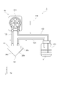
- FIG. 1 is a configuration diagram of the attenuated total reflection spectroscopic device of the first embodiment.
- FIG. 2 is a configuration diagram of an adjustment unit according to the first embodiment.
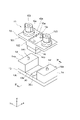
- 3 is an exploded perspective view of the holding portion shown in FIG. 2;
- FIG. 4 is a cross-sectional view along line IV--IV of FIG. 3.
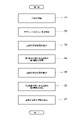
- FIG. 5 is a flow chart of the attenuated total reflection spectroscopy method of the first embodiment.
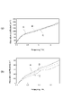
- FIG. 6 is a diagram showing the results of the attenuated total reflection spectroscopy method of the first embodiment.
- FIG. 7 is a diagram showing the results of the attenuated total reflection spectroscopy method of the second embodiment.
- FIG. 1 is a configuration diagram of the attenuated total reflection spectroscopic device of the first embodiment.
- FIG. 2 is a configuration diagram of an adjustment unit according to the first embodiment.
- 3 is an exploded perspective view of the holding portion shown in FIG. 2;
- FIG. 4 is a cross-section
- FIG. 8 is a cross-sectional view of a holding portion and an adjusting portion of a modified example.
- FIG. 9 is a configuration diagram of the attenuated total reflection spectroscopic device of the second embodiment.
- FIG. 10 is a configuration diagram of the temperature adjustment unit shown in FIG. 9.
- FIG. 11 is an exploded perspective view of the heat transfer section shown in FIG. 10.
- FIG. 12 is a diagram showing the results of comparative examples and examples.
- FIG. 13 is a configuration diagram of a temperature control unit of a modified example.
- the attenuated total reflection spectroscopic device 1 of the first embodiment includes a light output unit 20, a prism (optical element) 30, an optical path length difference adjusting unit 40, a polarizer 50, and a multiplexing unit. It includes a section 60 , a photodetector section 70 and a processing section 80 .
- the attenuated total reflection spectroscopy device 1 is a device for acquiring information about the sample S by performing, for example, an attenuated total reflection spectroscopy (ATR) method using terahertz waves.
- ATR attenuated total reflection spectroscopic device 1
- the ATR device 1 is used, for example, as a quality analysis tool in the manufacturing process of pharmaceuticals, foods, chemical materials, etc., or as an analysis tool in the research and development stage of pharmaceuticals, foods, chemical materials, etc.
- the optical output unit 20 outputs terahertz waves T as light.
- the light output section 20 has a light source 21, a branch section 22, a chopper 23, a plurality of mirrors M1 to M3, and a terahertz wave generation element .
- the light source 21 outputs light by pulse oscillation.
- the light source 21 is, for example, a femtosecond pulsed laser light source that outputs pulsed laser light having a pulse width of approximately femtoseconds.
- the branching unit 22 is, for example, a beam splitter or the like.
- the splitter 22 splits the light output from the light source 21 into the pump light P1 and the probe light P2.
- the chopper 23 alternately repeats passage and blocking of the pump light P1 output from the splitter 22 at a constant cycle.
- Each of the mirrors M1 to M3 sequentially reflects the pump light P1 that has passed through the chopper .
- the pump light P1 that has passed through the chopper 23 is incident on the terahertz wave generating element 24 after being sequentially reflected by the mirrors M1 to M3.
- the optical system of the pump light P1 from the splitter 22 to the terahertz wave generating element 24 will be referred to as "pump optical system”.
- the terahertz wave generating element 24 outputs the terahertz wave T upon receiving the pump light P1 reflected by the mirror M3.
- the terahertz wave generating element 24 includes, for example, a nonlinear optical crystal (such as ZnTe), a photoconductive antenna element (such as an optical switch using GaAs), a semiconductor (such as InAs), or a superconductor.
- a nonlinear optical crystal such as ZnTe
- a photoconductive antenna element such as an optical switch using GaAs
- a semiconductor such as InAs
- the terahertz wave T is an electromagnetic wave having a frequency of about 0.01 THz to 100 THz, which corresponds to the intermediate range between light waves and radio waves, and has intermediate properties between light waves and radio waves.
- the terahertz wave T is generated at a constant repetition period and has a pulse width of several picoseconds. That is, the terahertz wave generating element 24 generates a pulsed light train including a plurality of terahertz waves T arranged at predetermined time intervals (pulse intervals).
- the optical system of the terahertz wave T from the terahertz wave generation element 24 to the multiplexer 60 is referred to as "terahertz wave optical system".
- the prism 30 is, for example, a so-called aplanatic prism or the like.
- the cross section of the prism 30 has, for example, a triangular shape.
- the prism 30 has an incident surface 30a, an exit surface 30b and a reflecting surface 30c. Each of the entrance surface 30a and the exit surface 30b obliquely intersects the reflection surface 30c.
- the reflecting surface 30c is a total reflecting surface.
- a sample S is held on the reflecting surface 30c.
- the prism 30 is transparent to the terahertz wave T output from the terahertz wave generating element 24 .
- the refractive index of the prism 30 is greater than the refractive index of the sample S.
- the material of the prism 30 is silicon or the like, for example.
- the terahertz wave T that has entered the incident surface 30a of the prism 30 enters the reflecting surface 30c from the side opposite to the sample S, is reflected by the reflecting surface 30c, and is output to the outside from the exit surface 30b.
- Sample S contains a suspension.
- the sample S contains a liquid and suspended matter dispersed in the liquid. Suspended matter is not dissolved in a liquid.
- Liquids are, for example, pure water, distilled water, saline, blood, ethanol, methanol, acetone, ethyl acetate, isopropanol, dioxane, dimethylsulfoxide, dimethylformamide, formamide, formic acid, butyric acid, sulfuric acid, hydrochloric acid, acetic acid, nitric acid. , trifluoroacetic acid, or phosphoric acid.
- Suspending substances are, for example, calcium sulfate (gypsum), carbamazepine, theophylline, or nifedipine. In this embodiment, the liquid is pure water and the suspended matter is nifedipine.
- the optical path length difference adjusting section 40 has a plurality of mirrors M4 to M8.
- the probe light P2 output from the splitter 22 is sequentially reflected by each of the mirrors M4 to M8, passes through the polarizer 50, and enters the multiplexer 60.
- the optical system of the probe light P2 from the splitter 22 to the multiplexer 60 is hereinafter referred to as a "probe optical system".
- the optical path length difference adjusting unit 40 the optical path length between the mirrors M4 and M5 and the optical path length between the mirrors M6 and M7 are adjusted by moving the mirrors M5 and M6. The optical path length is adjusted.
- the optical path length difference adjusting unit 40 can be configured so that "the optical path of the pump optical system and the terahertz wave optical system from the branching unit 22 to the combining unit 60" and "the probe optical system from the branching unit 22 to the combining unit 60" Adjust the difference between the optical path of
- the multiplexing unit 60 is, for example, a film-like mirror adhered to a rigid support frame and stretched thinly.
- the multiplexer 60 is, for example, a pellicle.
- the photodetector 70 detects the terahertz wave T output from the prism 30 .
- the photodetector 70 includes a terahertz wave detection element 71, a quarter wave plate 72, a polarization separation element 73, a photodetector 74a, a photodetector 74b, a differential amplifier 75, a lock-in amplifier 76;
- the terahertz wave detection element 71 detects the correlation between the terahertz wave T and the probe light P2.
- the terahertz wave detection element 71 includes an electro-optic crystal.
- the terahertz wave T and the probe light P2 are incident on the terahertz wave detection element 71, birefringence is induced in the terahertz wave detection element 71 by the Pockels effect as the terahertz wave T propagates.
- the probe light P2 changes its polarization state due to the birefringence and is output from the terahertz wave detection element 71 .
- the birefringence amount at this time depends on the electric field strength of the terahertz wave T.
- FIG. Therefore, the amount of change in the polarization state of the probe light P2 in the terahertz wave detection element 71 depends on the electric field intensity of the terahertz wave T.
- the probe light P2 output from the terahertz wave detection element 71 passes through the quarter-wave plate 72 and enters the polarization separation element 73 .
- the polarization separation element 73 is, for example, a Wollaston prism or the like.
- the polarization separation element 73 separates the incident probe light P2 into two mutually orthogonal polarization components and outputs them.
- Each of the photodetectors 74a and 74b includes, for example, a photodiode.
- Each of the photodetectors 74 a and 74 b detects the power of the two polarized components of the probe light P 2 and outputs an electrical signal having a value corresponding to the detected power to the differential amplifier 75 .
- the differential amplifier 75 receives the electrical signals output from the photodetectors 74a and 74b, respectively, and outputs an electrical signal having a value corresponding to the difference between the values of the respective electrical signals to the lock-in amplifier 76. do.
- the lock-in amplifier 76 synchronously detects the electrical signal output from the differential amplifier 75 at the repetition frequency of passage and interruption of the pump light P1 in the chopper 23 .
- a signal output from the lock-in amplifier 76 has a value that depends on the electric field strength of the terahertz wave T.
- the photodetector 70 detects the correlation between the terahertz wave T and the probe light P2, and detects the electric field amplitude of the terahertz wave T.
- the processing unit 80 is electrically connected to the lock-in amplifier 76.
- the processing unit 80 acquires information about the sample S based on the detection result detected by the photodetector 70 .
- the processing unit 80 is composed of a CPU (Central Processing Unit), a ROM (Read Only Memory), a RAM (Random Access Memory), and the like.
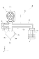
- the ATR device 1 includes a holding section 11 and an adjusting section 12 . Note that illustration thereof is omitted in FIG.
- the holding part 11 holds the sample S on the reflecting surface 30 c of the prism 30 .
- the adjustment section 12 includes a pump 121 , a container 122 , multiple tubes 123 and an output control section 124 .
- the pump 121 is connected to each of the container 122 and the holding section 11 by tubes 123 .
- the holding part 11 is connected to the container 122 by the tube 123 .
- a sample S is accommodated in the container 122 .
- the sample S is circulated among the pump 121 , the container 122 and the holder 11 by being sucked and pumped by the pump 121 .
- the output control unit 124 controls the output of the pump 121. As the output of the pump 121 increases, the flow velocity of the sample S between the pump 121, the container 122 and the holder 11 increases. When the output of the pump 121 becomes smaller, the flow velocity of the sample S between the pump 121, the container 122 and the holder 11 becomes smaller.
- the output control unit 124 is composed of a CPU (Central Processing Unit), a ROM (Read Only Memory), a RAM (Random Access Memory), and the like.
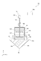
- the holding part 11 has a substrate 13, a pair of supports 14, a mounting part 15, a holding body 16, and a sealing member 17 (see FIG. 4).
- the substrate 13 holds the prism 30 so that the reflecting surface 30c is orthogonal to the Z-axis direction, and the incident surface 30a and the output surface 30b are orthogonal to the X-axis direction.
- the reflecting surface 30c is substantially flush with the surface 13a of the substrate 13.
- the terahertz waves T can be incident on the entrance surface 30a and emitted from the exit surface 30b on the back surface 13b side of the substrate 13.
- Each support 14 is fixed to the surface 13 a of the substrate 13 .
- a pair of supports 14 are arranged on both sides of the prism 30 in the Y-axis direction.
- Each support 14 has, for example, a rectangular parallelepiped shape whose length direction is the X-axis direction.
- a pin 141 is provided on each mounting surface 14 a of each support 14 opposite to the substrate 13 .
- the mounting portion 15 includes a plate 151 , a cylinder 152 and a pair of fixing members 153 .
- the plate 151 has, for example, a rectangular plate shape.
- the plate body 151 has a length direction in the Y-axis direction and a thickness direction in the Z-axis direction.
- the width of the plate 151 in the X-axis direction is substantially the same as the width of the support 14 in the X-axis direction.
- the width of the plate 151 in the Y-axis direction is substantially the same as the distance between the end faces of the pair of supports 14 in the Y-axis direction (the end faces on the side opposite to the prism in the Y-axis direction).
- a through hole 15 a is formed in the plate 151 .
- the through-hole 15a has, for example, a rectangular shape whose length is in the X-axis direction when viewed from the Z-axis direction.
- the cylinder 152 is provided on one main surface of the plate 151 .
- the tubular body 152 has, for example, a rectangular tubular shape.
- the cylindrical body 152 extends along the Z-axis direction. When viewed from the Z-axis direction, the cylindrical body 152 has, for example, the X-axis direction as its length direction.
- the cylinder 152 surrounds the through hole 15a of the plate 151 when viewed from the Z-axis direction.
- the width of the cylinder 152 in the Y-axis direction is smaller than the distance between the pair of supports 14 in the Y-axis direction.
- the cylinder 152 is fixed to the plate 151 .
- Each fixing member 153 is provided on the opposite side of the plate 151 from the cylinder 152 .
- a pair of fixing members 153 are provided on both sides of the through-hole 15a and the cylinder 152 in the Y-axis direction. Each fixing member 153 penetrates the plate 151 .
- the holder 16 has a rectangular parallelepiped shape with the X-axis direction as the length direction.
- the holder 16 is housed inside the cylindrical body 152 .
- the plate 151 of the mounting portion 15 is mounted on the mounting surface 14a of each support 14 so that the cylinder 152 containing the holder 16 is positioned between the plate 151 and the prism 30.
- Each fixing member 153 is fixed to a pin 141 provided on each support 14 . Thereby, the holder 16 is attached to the prism 30 .
- the holder 16 has a first main surface 16a orthogonal to the Z-axis direction and a second main surface 16b opposite to the first main surface 16a.
- the first main surface 16 a is exposed from the through hole 15 a of the plate 151 .
- the second main surface 16 b protrudes from the end of the cylinder 152 opposite to the plate 151 .
- the holder 16 has a recess 16c, an introduction hole 16d, and an extraction hole 16e.
- the recess 16c is formed in the second main surface 16b.
- the recess 16c is recessed by a predetermined depth from the second main surface 16b.
- the recess 16c has, for example, a rectangular shape with the X-axis direction as the length direction.
- the introduction hole 16d and the outlet hole 16e are arranged in the Z-axis direction.
- the introduction hole 16d communicates with the recess 16c.
- the introduction hole 16d extends along the Z-axis direction.
- the introduction hole 16d penetrates the holder 16 in the Z-axis direction.
- 16 d of introduction holes are opened in the 1st main surface 16a and the bottom face of the recessed part 16c.
- the introduction hole 16d has, for example, a circular shape when viewed from the Z-axis direction.
- a tube 123 is connected to the opening of the introduction hole 16d in the first main surface 16a (see FIG. 2).
- the lead-out hole 16e communicates with the recess 16c.
- the lead-out hole 16e extends along the Z-axis direction.
- the lead-out hole 16e penetrates the holder 16 in the Z-axis direction.
- the lead-out hole 16e opens to the first main surface 16a and the bottom surface of the recess 16c.
- the lead-out hole 16e has, for example, a circular shape when viewed from the Z-axis direction.
- a tube 123 is connected to the opening of the lead-out hole 16e in the first main surface 16a (see FIG. 2).
- the holder 16 is arranged on the reflecting surface 30c of the prism 30 so that the second main surface 16b faces the reflecting surface 30c.
- a portion of the holding body 16 on the first main surface 16 a side is held by the cylindrical body 152 of the mounting portion 15 .
- the first main surface 16 a is in contact with the plate 151 of the mounting portion 15 .
- the holder 16 is pressed against the reflecting surface 30c by the mounting portion 15.
- the concave portion 16c of the holder 16 and the reflecting surface 30c define a storage space R in which the sample S is stored.
- the sample S is introduced into the accommodation space R by flowing through the introduction hole 16d.
- the sample is led out from the accommodation space R by flowing through the lead-out hole 16e.
- the holder 16 has transparency to visible light.
- the material of the holder 16 is acrylic, for example.
- the sealing member 17 is, for example, an O-ring.
- the sealing member 17 is arranged in the recess 16c.
- the sealing member 17 extends along the outer edge of the recess 16c.
- the sealing member 17 is arranged outside the introduction hole 16d and the outlet hole 16e when viewed in the Z-axis direction.
- the sealing member 17 seals the accommodation space R. As shown in FIG.
- the adjustment unit 12 acquires a first detection result regarding the sample S in the first flowing state, The flow state of the sample S is adjusted to the first flow state, and the flow state of the sample S is adjusted to the second flow state in order to obtain a second detection result for the sample S in the second flow state.
- the flow state of the sample S refers to the kinetic energy of the sample S held on the reflecting surface 30 c of the prism 30 .
- the state of flow of the sample S is said to be strong, and when the kinetic energy of the sample S is small, the state of flow of the sample S is said to be weak.
- the flow velocity of the sample S is high, the flow state of the sample S is strong, and when the flow velocity of the sample S is low, the flow state of the sample S is weak.
- the flow state of the sample S is strong, and when the sample S is weakly stirred, the flow state of the sample S is weak.
- the suspended solids in the sample S tend to disperse uniformly in the sample S. Suspended substances in the sample S tend to precipitate in the sample S when the flow state of the sample S is weak.
- the amount of suspended solids at a position close to the reflecting surface 30c in this embodiment, a position closer to the reflecting surface 30c than the bottom surface of the recess 16c in the accommodation space R
- the amount of liquid at positions close to the reflecting surface 30c is relatively large.
- the amount of suspended matter at positions near the reflecting surface 30c is relatively large, and the amount of liquid at positions near the reflecting surface 30c is relatively small.
- the adjustment section 12 circulates the sample S between the container 122 and the holder 16 .
- the output control unit 124 drives the pump 121 .
- the pump 121 circulates the sample S from the lead-out hole 16e to the introduction hole 16d.
- the sample S contained in the container 122 is sucked by the pump 121 and supplied to the introduction hole 16 d of the holder 16 via the tube 123 .
- the sample S supplied to the introduction hole 16d is introduced into the accommodation space R by flowing through the introduction hole 16d.
- the sample S introduced into the accommodation space R passes through the accommodation space R and is drawn out from the accommodation space R by flowing through the lead-out hole 16e.
- the sample S led out from the lead-out hole 16 e is pumped by the pump 121 and supplied to the container 122 again through the tube 123 .
- the sample S supplied to the container 122 is supplied again to the introduction hole 16 d by the suction of the pump 121 .
- a circulation path for the sample S is formed in the ATR device 1 .
- the output control unit 124 changes the flow state of the sample S held on the reflecting surface 30c (the sample S housed in the housing space R) to the first flow state. .
- the output control unit 124 maintains the first flow state of the sample S for a predetermined period. Specifically, the output control unit 124 increases the output of the pump 121 to increase the flow velocity of the sample S in the circulation path.
- the output control unit 124 maintains the increased output of the pump 121 for a predetermined period of time, thereby maintaining the increased flow velocity of the sample S in the circulation path for a predetermined period of time.
- the output control unit 124 changes the flow state of the sample S held on the reflecting surface 30c (the sample S housed in the housing space R) to the second flow state. .
- the first flow state is stronger than the second flow state.
- the output control unit 124 maintains the second flow state of the sample S for a predetermined period.
- the output control unit 124 reduces the flow velocity of the sample S in the circulation path by reducing the output of the pump 121 .
- the flow velocity of the sample S when obtaining the first detection result of the sample S is higher than the flow velocity of the sample S when obtaining the second detection result of the sample S.
- the output control unit 124 maintains the reduced output of the pump 121 for a predetermined period of time, thereby maintaining the reduced flow velocity of the sample S in the circulation path for a predetermined period of time.
- the first detection result is the detection result regarding the liquid in the sample S.
- the first detection result is, for example, data detected by the photodetector 70 and data for calculating the spectral information of the liquid in the sample S.
- the second detection result is a detection result regarding suspended solids in the sample S.
- the second detection result is, for example, data detected by the photodetector 70 and is data for calculating spectral information of suspended solids in the sample S.
- the ATR device 1 is a flow-through type device that can continuously monitor parameters necessary for quality control of the sample S, for example. Such an ATR device 1 is easy to introduce into the manufacturing process.
- the sample S containing suspension is held on the reflecting surface 30 c of the prism 30 .
- the adjustment unit 12 adjusts the flow state of the sample S to the first flow state in order to obtain a first detection result for the sample S in the first flow state, and performs second detection for the sample S in the second flow state.
- the flow state of the sample S is adjusted to the second flow state. Accordingly, by making the first flow state relatively strong, the amount of suspended solids in the sample S at a position near the reflecting surface 30c can be relatively reduced, and the content of suspended solids is relatively small.
- a detection result regarding the sample S can be obtained as a first detection result.
- the amount of suspended solids in the sample S at a position close to the reflecting surface 30c can be relatively increased, and a sample containing a relatively large amount of suspended solids can be obtained.
- a detection result for S can be obtained as a second detection result.
- the holding section 11 includes a holding body 16 arranged on the reflecting surface 30c.
- the holder 16 includes a recess 16c that defines the housing space R for the sample S together with the reflecting surface 30c, an introduction hole 16d that communicates with the recess 16c and through which the sample S introduced into the housing space R flows, and the recess 16c, and a lead-out hole 16e through which the sample S led out from the accommodation space R flows.
- the adjusting section 12 includes a pump 121 that circulates the sample S from the lead-out hole 16 e to the introduction hole 16 d, and an output control section 124 that controls the output of the pump 121 . Thereby, the sample S held on the reflecting surface 30c can be caused to flow by the pump 121 . Further, by controlling the output of the pump 121, the flow velocity of the sample S held on the reflecting surface 30c can be controlled, and the flow state of the sample S can be adjusted.
- the holder 16 has transparency to visible light. Thereby, the flow state of the sample S held on the reflecting surface 30c can be visually observed.
- the ATR device 1 includes a light output unit 20 that outputs the terahertz wave T to the reflecting surface 30c from the side opposite to the sample S, and a light detecting unit 70 that detects the terahertz wave T reflected by the reflecting surface 30c. I have.
- the adjustment unit 12 adjusts the flow state of the sample S while the photodetection unit 70 detects the terahertz wave T. As shown in FIG. Thereby, the first detection result and the second detection result regarding the sample S can be easily obtained during the detection period of the terahertz wave T.
- the light output from the light output section 20 is the terahertz wave T.
- the terahertz wave T can be used to obtain the first detection result and the second detection result regarding the sample S with high accuracy.
- the range (range in the Z-axis direction) of the evanescent wave leaking out from the reflecting surface 30c becomes relatively large. This widens the measurable area.
- ATR method an attenuated total reflection spectroscopy method (hereinafter referred to as "ATR method") performed in the ATR device 1 for obtaining information about the sample S will be described.
- step S1 the sample S is supplied to the accommodation space R (step S1).
- step S ⁇ b>1 after securing the amount of the sample S contained in the container 122 , the output control section 124 drives the pump 121 .
- the pump 121 When the pump 121 is driven, the sample S is circulated in the circulation path.
- the sample S flows through the accommodation space R. Thereby, the sample S is held on the reflecting surface 30c.
- Step S1 corresponds to the first step.
- step S2 the terahertz wave T is output from the side opposite to the sample S to the reflecting surface 30c, and the terahertz wave T reflected by the reflecting surface 30c is detected (step S2).
- step S ⁇ b>2 the light output unit 20 causes the terahertz wave T to enter the incident surface 30 a of the prism 30 .
- step S2 the correlation between the terahertz wave T output from the multiplexer 60 and the probe light P2 is detected by the photodetector 70, and the electric field amplitude of the terahertz wave T is detected.
- step S2 the terahertz wave T is continuously output to the reflecting surface 30c, and the terahertz wave T reflected by the reflecting surface 30c is continuously detected.
- Step S2 corresponds to the sixth step.
- step S3 the flow state of the sample S is adjusted so that the sample S held on the reflecting surface 30c is in the first flow state
- step S3 corresponds to the second step.
- step S4 a first detection result regarding the sample S in the first flowing state is obtained (step S4).
- step S4 corresponds to the third step.
- step S5 the flow state of the sample S is adjusted so that the sample S held on the reflecting surface 30c is in the second flow state.
- step S5 corresponds to the fourth step.
- step S6 corresponds to the fifth step.
- step S7 information about the sample S is acquired based on the first detection result and the second detection result.
- step S7 for example, spectral information on each of the liquid and suspended matter in the sample S is calculated.
- Step S7 corresponds to the seventh step.
- Steps S3 to S6 are performed during the period during which step S2 is performed, that is, during the period during which the terahertz wave T is output to the reflecting surface 30c and the terahertz wave T reflected by the reflecting surface 30c is detected. be done.
- step S4 the first detection result regarding the sample S in the first flow state is obtained, and in step S6, the second detection result regarding the sample S in the second flow state is obtained. are getting Accordingly, by making the first flow state relatively strong in step S3, the amount of suspended solids in the sample S at a position close to the reflecting surface 30c can be relatively reduced. A detection result for the sample S containing a relatively small amount of substance can be obtained as the first detection result. Further, by making the second flow state relatively weak in step S5, the amount of suspended solids in the sample S at a position close to the reflecting surface 30c can be relatively increased. can be obtained as the second detection result for the sample S containing a relatively large amount of .
- the first flow state is stronger than the second flow state. Therefore, the first detection result and the second detection result regarding the sample S can be reliably obtained.
- the ATR method comprises step S2.
- step S2 the terahertz wave T is output to the reflecting surface 30c from the side opposite to the sample S, and the terahertz wave T reflected by the reflecting surface 30c is detected.
- Steps S3 to S6 are performed during the period in which step S2 is performed. Thereby, the first detection result and the second detection result regarding the sample S can be easily obtained during the detection period of the terahertz wave T.
- the light is terahertz waves T.
- the terahertz wave T can be used to obtain the first detection result and the second detection result regarding the sample S with high accuracy.
- the ATR method includes step S7 of acquiring information about the sample S based on the first detection result and the second detection result. Thereby, detailed information about the sample S can be easily obtained as described above.
- FIG. 6 is a diagram showing the results of the ATR method of the first embodiment.
- sample S information about each of the sample A, the sample B, and the sample C was acquired.
- sample A, sample B and sample C is a suspension in which nifedipine (suspended matter) is dispersed in pure water (liquid).
- the concentration of nifedipine in sample A is around 2.5 mg/ml.
- the concentration of nifedipine in sample B is around 5.0 mg/ml.
- the concentration of nifedipine in sample C is around 10.0 mg/ml.
- FIG. 6 is a diagram showing absorption spectra obtained from the first detection results of the samples A, B, and C in the first flow state.
- (b) of FIG. 6 is a diagram showing absorption spectra obtained from the second detection results of the samples A, B, and C in the second flow state.
- the absorption spectra of Sample A, Sample B, and Sample C in the first flow state smoothly increase as the frequency increases and substantially overlap.
- the absorption spectra of the samples A, B, and C in the second flow state have peaks (suspensions) at predetermined frequencies (1.1 to 1.3 THz) unique peaks from turbidity) and are separated from each other.
- the sample S when the sample S is in the first flow state, it is possible to obtain the detection result regarding the liquid in the sample S, and when the sample S is in the second flow state, the sample It was confirmed that it is possible to obtain detection results for suspended solids in S.
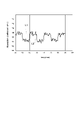
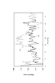
- FIG. 7 is a diagram showing the results of the ATR method of the second embodiment.
- a suspension in which gypsum (suspended matter) is dispersed in pure water (liquid) is used as the sample S, and the flow state of the sample S alternates between the first flow state and the second flow state.
- the flow state of the sample S was adjusted so as to switch to FIG. 7 is a diagram showing temporal changes in the absorption spectrum of the sample S corresponding to a predetermined frequency (for example, about 0.5 THz).
- a predetermined frequency for example, about 0.5 THz
- a line L1 indicates an absorption spectrum corresponding to the liquid of the sample S, that is, the liquid (pure water in this embodiment) in which suspended solids are not dispersed in the sample S, and the line L2 indicates the time change of the absorption spectrum corresponding to the sample S;
- the absorption spectrum of the portion of the line L2 corresponding to the first flow state substantially matches the absorption spectrum of the sample S liquid.
- a portion of the line L2 corresponding to the second flow state (for example, 55 to 60 minutes) is away from the line L1.
- the present disclosure is not limited to the first embodiment described above.
- the ATR device 1A may have a holding section 18 instead of the holding section 11 .
- the ATR device 1A may include an adjustment section 19 instead of the adjustment section 12 . Since other configurations of the ATR device 1A are the same as those of the ATR device 1, detailed description thereof will be omitted.
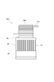
- the holding part 18 includes a holding body 180 .
- the holder 180 has a side wall portion 181 and a bottom wall portion 182 .
- the side wall portion 181 has a tubular shape.
- the bottom wall portion 182 seals one opening of the side wall portion 181 .
- the other opening of side wall portion 181 is open.
- the holding body 180 is arranged on the reflecting surface 30c of the prism 30 so that the end surface 18a of the side wall portion 181 opposite to the bottom wall portion 182 faces the reflecting surface 30c of the prism 30 .
- the inner surface 18b of the holder 180 defines a storage space R for storing the sample S together with the reflecting surface 30c.
- the adjustment section 19 has a shaft 191 , a plurality of propellers 192 , a motor 193 and an output control section 194 .
- the shaft 191 extends along the Z-axis direction.
- the shaft 191 penetrates the bottom wall portion 182 and extends to the accommodation space R.
- Each propeller 192 is fixed to the shaft 191 in the accommodation space R.
- the motor 193 is provided on the shaft 191 outside the accommodation space R. As shown in FIG. Motor 193 rotates shaft 191 .
- the output control section 194 controls the output of the motor 193 .
- the output control unit 194 is composed of a CPU (Central Processing Unit), a ROM (Read Only Memory), a RAM (Random Access Memory), and the like.
- the adjustment unit 19 can adjust the flow state of the sample S.
- the adjustment unit 19 stirs the sample S in the accommodation space R.
- the output control unit 194 drives the motor 193 .
- the shaft 191 to which the propellers 192 are fixed rotates.
- the sample S accommodated in the accommodation space R is stirred by each propeller 192 .
- the output control unit 194 changes the flow state of the sample S held on the reflecting surface 30c (the sample S housed in the housing space R) to the first flow state. .
- the output control unit 194 maintains the first flow state of the sample S for a predetermined period.
- the output control unit 194 increases the rotation speed of the shaft 191 by increasing the output of the motor 193 .
- the output control unit 194 maintains the increased output of the motor 193 for a predetermined period of time, thereby maintaining the increased rotational speed of the shaft 191 for a predetermined period of time.
- the output control unit 194 changes the flow state of the sample S held on the reflecting surface 30c (the sample S housed in the housing space R) to the second flow state. .
- the output control unit 194 maintains the second flow state of the sample S for a predetermined period. Specifically, the output control unit 194 reduces the rotation speed of the shaft 191 by reducing the output of the motor 193 .
- the rotation speed of the shaft 191 when obtaining the first detection result regarding the sample S is higher than the rotation speed of the shaft 191 when obtaining the second detection result regarding the sample S.
- the output control unit 194 maintains the reduced output of the motor 193 for a predetermined period of time, thereby maintaining the reduced rotational speed of the shaft 191 for a predetermined period of time.
- the ATR device 1A As with the ATR device 1, it is possible to easily acquire detailed information about the sample S.
- the output control unit 124 increases or decreases the output of the pump 121 in the first embodiment, the output control unit 124 stops the flow of the sample S in the circulation path by stopping the pump 121. You may let That is, the second fluid state may be a state of rest. Thereby, the suspended solids in the sample S held on the reflecting surface 30c can be precipitated, and the detection result regarding the sediment made up of the suspended solids can be obtained as the second detection result.
- the output control unit 194 of the modified example may also stop the rotation of each propeller 192 by stopping the motor 193 .
- the sample S may contain a plurality of types of suspended solids having different specific gravities.
- the sample S may contain, for example, each of a first suspended solid having a first specific gravity, a second suspended solid having a second specific gravity, and a third suspended solid having a third specific gravity.
- the output control unit 124 adjusts the flow state of the sample S so that the sample S held on the reflecting surface 30c is in various flow states (eg, first flow state, second flow state, third flow state, etc.). You may Thereby, for example, the flow state of the sample S can be changed according to the specific gravity of the suspended matter to be measured among the first suspended matter, the second suspended matter and the third suspended matter.
- the material of the holder 16 may be, for example, a fluorine resin such as Teflon (registered trademark).
- the material of the holder 16 may be, for example, aluminum.
- the light output unit 20 outputs terahertz waves T as light, but the light output unit 20 may output ultraviolet rays or infrared rays (near infrared rays, middle infrared rays, or far infrared rays). good.
- the ATR device 1 may be a device that uses light in the ultraviolet region or the infrared region as well as in the terahertz band.
- step S1 may also be performed during the period in which step S2 is performed.
- steps S3 and S4 may be performed after steps S5 and S6 are performed.
- the optical element may be, for example, a plate-shaped optical member such as a slide glass, or an optical fiber.
- the output control unit 124 drives the pump 121 in one direction.
- the sample S is caused to flow in one direction, but the output control unit 124 drives the pump 121 in one direction, for example, when acquiring the first detection result regarding the sample S.
- the pump 121 is driven in the direction opposite to the one direction to move the sample S in the direction opposite to the one direction. may flow to That is, in each of the first flow state and the second flow state of the sample S, the flow direction of the sample S may be different.
- the output control unit 194 drives the motor 193 in one direction in both cases of obtaining the first detection result regarding the sample S and obtaining the second detection result regarding the sample S, so that the shaft
- the output control unit 194 drives the motor 193 in one direction to obtain the first detection result regarding the sample S, for example, so that the shaft 191 is rotated in one direction. is rotated in one direction to obtain a second detection result for the sample S, the shaft 191 is rotated in the direction opposite to the one direction by driving the motor 193 in the opposite direction to the one direction.
- the adjusting section 19 may adjust the flow state of the sample S by controlling each propeller 192 independently.
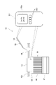
- the attenuated total reflection spectroscopic device 1B of the second embodiment (hereinafter referred to as "ATR device 1B") is different from the ATR device 1 of the first embodiment in that it further includes a temperature adjustment section 90. are different. Since other configurations of the ATR device 1B are the same as those of the ATR device 1, detailed description thereof will be omitted.
- the temperature adjustment section 90 is provided between the container 122 and the holding section 11 .
- the temperature adjustment section 90 is provided on the tube 123 connecting the pump 121 and the holding section 11 .
- the tube 123 connecting the pump 121 and the holding portion 11 is hereinafter referred to as the "introduction tube 123". That is, the introduction tube 123 is a tube for supplying the sample S to the holding section 11 .
- the temperature adjustment unit 90 is provided in the introduction pipe 123 at a position closer to the holding unit 11 than the pump 121 is.
- the temperature adjustment unit 90 adjusts the temperature of the sample S flowing through the introduction pipe 123 .
- the temperature adjuster 90 has a heat processor 91 , a detector 92 , and a controller (controller) 93 .
- the heat treatment section 91 is provided outside the introduction pipe 123 .
- the heat treatment section 91 heats or cools the sample S flowing through the introduction pipe 123 .
- the thermal processing section 91 has a heat transfer section 94 , a Peltier element 95 , a heat sink 96 and a cooling fan 97 .
- the heat transfer section 94 surrounds the introduction pipe 123 .
- the heat transfer section 94 is thermally connected to the introduction pipe 123 .
- the heat transfer section 94 has a pair of plate members 94a and 94b.
- Each plate member 94a, 94b is made of a material with relatively high thermal conductivity.
- the material of each plate member 94a, 94b is, for example, aluminum, copper, gold, silver, nickel, platinum, or the like. In this embodiment, the material of each plate member 94a, 94b is aluminum.
- a groove 94c is provided in each of the plate members 94a and 94b. Each groove 94c extends in a meandering manner.
- the introduction pipe 123 is sandwiched between the pair of plate members 94a and 94b while being arranged in each groove 94c. With such a configuration, the contact area between the introduction pipe 123 and the heat transfer section 94 increases, so the heat transfer efficiency of the heat transfer section 94 increases. Thereby, the temperature of the sample S flowing through the introduction pipe 123 can be adjusted more effectively.
- thermal conductive grease is filled between each groove 94c and the introduction pipe 123.
- the Peltier element 95 is provided on the surface of the heat transfer section 94 .
- the Peltier element 95 includes an element portion including a heat absorbing area and a heat generating area.
- the Peltier element 95 is thermally connected to the heat transfer section 94 .
- the Peltier element 95 heats or cools the heat transfer section 94 .
- the heat sink 96 is provided on the side opposite to the heat transfer section 94 with respect to the Peltier element 95 .
- a heat sink 96 is thermally connected to the Peltier element 95 .
- a coolant flows through the heat sink 96 .
- a heat sink 96 promotes heat dissipation of the Peltier element 95 .
- the cooling fan 97 is provided on the side opposite to the Peltier element 95 with respect to the heat sink 96 .
- the cooling fan 97 is thermally connected with the heat sink 96 .
- a cooling fan 97 cools the heat sink 96 .
- the detection unit 92 detects the temperature of the sample S flowing through the introduction pipe 123 (hereinafter referred to as "the temperature of the sample S").
- the detector 92 has a temperature sensor 98 and a seal member 99 .
- a tip portion of the temperature sensor 98 is inserted into the introduction pipe 123 between the heat transfer portion 94 and the holding portion 11 .
- the temperature sensor 98 is, for example, a thermocouple or a resistance temperature detector.
- the seal member 99 is provided at a portion of the introduction pipe 123 into which the temperature sensor 98 is inserted.
- the seal member 99 partially covers the introduction pipe 123 and the temperature sensor 98 .
- the seal member 99 prevents the sample S flowing through the introduction pipe 123 from leaking outside the introduction pipe 123 .
- the controller 93 controls the output of the heat treatment section 91 .
- Controller 93 is electrically connected to each of temperature sensor 98 and Peltier element 95 .
- Controller 93 receives a signal from temperature sensor 98 .
- the controller 93 performs feedback control to the Peltier element 95 based on the detection result of the temperature sensor 98 .
- the controller 93 increases or decreases the output of the Peltier element 95 based on the detection result of the temperature sensor 98 .
- the controller 93 sends a cooling signal to the Peltier element 95 and causes the Peltier element 95 to cool the heat transfer section 94 .
- the controller 93 sends a heating signal to the Peltier element 95 to cause the Peltier element 95 to heat the heat transfer section 94 .
- the upper limit threshold and the lower limit threshold may be different from each other, or may be the same as each other.
- the controller 93 has a CPU (Central Processing Unit), ROM (Read Only Memory), RAM (Random Access Memory), and the like.
- the controller 93 has a monitor 93a and a plurality of switches 93b. For example, the temperature of the sample S and the upper threshold or lower threshold are displayed on the monitor 93a. In the example shown in FIG. 10, the temperature of the sample S is 25.8 degrees, and the upper and lower thresholds are 25.0 degrees.
- Each switch 93b has a function for instructing ON/OFF of the operation of the thermal processing unit 91, heating processing by the Peltier element 95, cooling processing by the Peltier element 95, display on the monitor 93a, or the like. The respective transmission of the cooling signal and heating signal to the Peltier element 95 may be performed automatically by the controller 93 or manually by the switch 93b.
- the ATR device 1B includes the introduction pipe 123 for supplying the sample S to the holding unit 11 and the temperature adjustment unit 90 for adjusting the temperature of the sample S flowing through the introduction pipe 123. Accordingly, by adjusting the temperature of the sample S flowing through the introduction pipe 123, the temperature of the sample S held by the holding section 11 can be kept constant. Therefore, the influence of the temperature change of the sample S on the measurement results can be suppressed.
- the temperature adjustment unit 90 can adjust the temperature of the sample S in real time and quickly by performing a heat treatment or a cooling treatment on the relatively small volume of the sample S flowing through the introduction pipe 123 . Therefore, detailed information about the sample S can be obtained with high accuracy. If the temperature of the sample S changes, the measurement results may also change.
- the temperature adjustment unit 90 includes a heat treatment unit 91 that heats or cools the sample S flowing through the introduction pipe 123, a detection unit 92 that detects the temperature of the sample S flowing through the introduction pipe 123, and the output of the heat treatment unit 91. and a controller 93 for controlling the The controller 93 increases or decreases the output of the thermal processor 91 based on the detection result of the detector 92 .
- the controller 93 increases or decreases the output of the thermal processor 91 based on the detection result of the detector 92 .
- the temperature adjustment section 90 is provided in the introduction pipe 123 , and the temperature sensor 98 is provided between the heat transfer section 94 and the holding section 11 .
- the temperature of the sample S can be detected at a position relatively close to the holding section 11 .
- the holding section 11 holds the sample S. It is possible to detect the temperature of the sample S with higher accuracy.
- the temperature adjustment section 90 is provided in the introduction pipe 123 at a position closer to the holding section 11 than the pump 121 is. According to this configuration, the temperature of the sample S can be detected at a position closer to the holding portion 11, and the temperature of the sample S held by the holding portion 11 can be detected with higher accuracy.
- the thermal processing section 91 includes a Peltier element 95 . This makes it possible to easily and reliably adjust the temperature of the sample S flowing through the introduction pipe 123 with high accuracy.
- FIG. 12 is a diagram showing the results of comparative examples and examples.
- the change over time of the refractive index of the sample S held by the holding part 11 was measured.
- heating of the sample S contained in the container 122 by the heater is started, and after about 40 minutes from the start of the measurement, the container 122 is heated.
- the heating by the heater of the sample S housed in was stopped.
- the ATR device of the comparative example differs from the ATR device 1B of the embodiment in that it does not include the temperature control unit 90. FIG. That is, in the comparative example, the temperature of the sample S flowing through the introduction pipe 123 was not adjusted.
- the refractive index L1 of the comparative example gradually increases after about 25 minutes have passed since the start of measurement, and gradually decreases after about 40 minutes have passed since the start of measurement. This result is considered to be caused by the temperature change of the sample S held by the holding part 11 since the sample S contained in the container 122 was heated. In contrast, no significant change over time was observed in the refractive index L2 of the example. As a result, since the temperature of the sample S flowing through the introduction pipe 123 is adjusted by the temperature adjusting unit 90, the sample S stored in the container 122 is heated, but the sample is held by the holding unit 11. It is believed that this is due to the fact that the temperature of S was kept constant.
- the thermal processing section 91 of the ATR device 1B may have a heat transfer section 94A instead of the heat transfer section 94.
- the heat transfer portion 94A may have a rod shape, for example.
- the introduction pipe 123 may be spirally wound around the heat transfer section 94A.
- the temperature adjustment section 90 may have a plurality of heat treatment sections 91 . Each heat treatment section 91 may be adjacent to each other outside the introduction pipe 123 .
- the temperature adjustment section 90 may have one detection section 92 corresponding to a plurality of heat treatment sections 91 .
- the temperature adjustment section 90 may have a plurality of detection sections 92 corresponding to each heat treatment section 91 .
- one controller 93 may control a plurality of heat treatment sections 91 and a plurality of or one detection section 92 .
- the temperature sensor 98 may be provided at any position in the flow path of the sample S as long as the temperature of the sample S can be detected.
- the tip of the temperature sensor 98 may be inserted into the introduction pipe 123 between the heat transfer section 94 and the pump 121, for example.
- the tip of the temperature sensor 98 may be inserted into the tube 123 between the pump 121 and the container 122 or between the container 122 and the holder 11, for example. In these cases, the detection of the temperature of the sample S can be flexibly handled as required, and the degree of freedom in designing the ATR device 1B can be improved.
- the sample S does not have to contain suspension.
- the sample S may not contain suspended matter dispersed in the liquid.
- the sample S may contain only liquid.
Landscapes
- Physics & Mathematics (AREA)
- Chemical & Material Sciences (AREA)
- Health & Medical Sciences (AREA)
- General Physics & Mathematics (AREA)
- Life Sciences & Earth Sciences (AREA)
- Analytical Chemistry (AREA)
- Biochemistry (AREA)
- General Health & Medical Sciences (AREA)
- Immunology (AREA)
- Pathology (AREA)
- Spectroscopy & Molecular Physics (AREA)
- Dispersion Chemistry (AREA)
- Toxicology (AREA)
- Investigating Or Analysing Materials By Optical Means (AREA)
Priority Applications (4)
| Application Number | Priority Date | Filing Date | Title |
|---|---|---|---|
| DE112022001785.6T DE112022001785T5 (de) | 2021-03-26 | 2022-01-31 | Vorrichtung zur abgeschwächten Totalreflexionsspektroskopie und Verfahren zur abgeschwächten Totalreflexionsspektroskopie |
| US18/283,296 US20240175811A1 (en) | 2021-03-26 | 2022-01-31 | Attenuated total reflectance spectroscopy apparatus, and attenuated total reflectance spectroscopy method |
| GB2314496.7A GB2619247A (en) | 2021-03-26 | 2022-01-31 | Attenuated total reflectance spectroscopy apparatus, and attenuated total reflectance spectroscopy method |
| JP2023508729A JPWO2022201862A1 (enExample) | 2021-03-26 | 2022-01-31 |
Applications Claiming Priority (2)
| Application Number | Priority Date | Filing Date | Title |
|---|---|---|---|
| JP2021-052822 | 2021-03-26 | ||
| JP2021052822 | 2021-03-26 |
Publications (1)
| Publication Number | Publication Date |
|---|---|
| WO2022201862A1 true WO2022201862A1 (ja) | 2022-09-29 |
Family
ID=83396783
Family Applications (2)
| Application Number | Title | Priority Date | Filing Date |
|---|---|---|---|
| PCT/JP2022/003544 Ceased WO2022201862A1 (ja) | 2021-03-26 | 2022-01-31 | 全反射減衰分光装置及び全反射減衰分光方法 |
| PCT/JP2022/014044 Ceased WO2022203007A1 (ja) | 2021-03-26 | 2022-03-24 | 分散安定性評価方法及び分散安定性比較方法 |
Family Applications After (1)
| Application Number | Title | Priority Date | Filing Date |
|---|---|---|---|
| PCT/JP2022/014044 Ceased WO2022203007A1 (ja) | 2021-03-26 | 2022-03-24 | 分散安定性評価方法及び分散安定性比較方法 |
Country Status (5)
| Country | Link |
|---|---|
| US (2) | US20240175811A1 (enExample) |
| JP (2) | JPWO2022201862A1 (enExample) |
| DE (2) | DE112022001785T5 (enExample) |
| GB (2) | GB2619247A (enExample) |
| WO (2) | WO2022201862A1 (enExample) |
Families Citing this family (2)
| Publication number | Priority date | Publication date | Assignee | Title |
|---|---|---|---|---|
| WO2025115663A1 (ja) * | 2023-11-27 | 2025-06-05 | 国立研究開発法人理化学研究所 | テラヘルツ波拡散体およびその製造方法 |
| US12241821B1 (en) * | 2024-05-02 | 2025-03-04 | Kuwait University | Method for determining physical stability of suspensions |
Citations (7)
| Publication number | Priority date | Publication date | Assignee | Title |
|---|---|---|---|---|
| JP2000221136A (ja) * | 1999-01-29 | 2000-08-11 | Jasco Corp | 経時変化追跡方法および装置 |
| JP2002533305A (ja) * | 1998-12-18 | 2002-10-08 | ミレニアム ペトロケミカルズ インコーポレーテッド | 酢酸製造における工程管理方法 |
| JP2012202951A (ja) * | 2011-03-28 | 2012-10-22 | Toyota Motor Corp | 赤外分光分析装置およびその利用 |
| JP2013505462A (ja) * | 2009-09-22 | 2013-02-14 | ビーピー・コーポレーション・ノース・アメリカ・インコーポレーテッド | 中赤外分光法を用いて生物学的プロセスを測定するための方法及び装置 |
| JP2013152159A (ja) * | 2012-01-25 | 2013-08-08 | Hamamatsu Photonics Kk | 薬物評価方法及び薬物評価装置 |
| CN106841057A (zh) * | 2016-12-19 | 2017-06-13 | 福建农林大学 | 一种生物质预水解过程在线监测的方法与装置 |
| CN111504941A (zh) * | 2020-05-14 | 2020-08-07 | 中国人民解放军陆军军医大学第一附属医院 | 一种无标记评估响应性水凝胶响应特征的太赫兹衰减全反射技术平台 |
Family Cites Families (49)
| Publication number | Priority date | Publication date | Assignee | Title |
|---|---|---|---|---|
| US3478206A (en) * | 1967-11-13 | 1969-11-11 | Wilks Scientific Corp | Multipurpose sample cell for conventional and attenuated total reflection absorption spectroscopy of gaseous and solid samples |
| US3620675A (en) * | 1969-02-10 | 1971-11-16 | Upjohn Co | Apparatus for the measurement of dissolution rates |
| US4227083A (en) * | 1979-02-02 | 1980-10-07 | General Electric Company | Apparatus for infrared laser spectroscopy of room temperature vulcanizable silicone compositions |
| JPS5848621U (ja) | 1981-09-28 | 1983-04-01 | 株式会社日立製作所 | 反転装置 |
| US5051551A (en) * | 1989-05-18 | 1991-09-24 | Axiom Analytical, Inc. | Immersion probe for infrared internal reflectance spectroscopy |
| US5229611A (en) * | 1989-11-03 | 1993-07-20 | Horiba, Ltd. | Infrared microscopic spectrometer using the attenuated total reflection method |
| US5097129A (en) * | 1990-12-06 | 1992-03-17 | International Business Machines Corporation | Surface contamination detection using infrared-transparent fibers or attenuated total reflection crystals |
| DE4227813A1 (de) * | 1992-08-21 | 1994-02-24 | Kim Yoon Ok | Vorrichtung zur qualitativen und/oder quantitativen Bestimmung einer zu analysierenden Probe |
| US5338935A (en) * | 1992-09-25 | 1994-08-16 | Truett William L | Positioning device for infrared accessories in FTIR spectrometers |
| US5436454A (en) * | 1993-10-15 | 1995-07-25 | Nicolet Instrument Corporation | Optical probe for remote attenuated total reflectance measurements |
| US6395538B1 (en) * | 1999-07-16 | 2002-05-28 | Human Genome Sciences, Inc. | Method and system for providing real-time, in situ biomanufacturing process monitoring and control in response to IR spectroscopy |
| US20040147034A1 (en) * | 2001-08-14 | 2004-07-29 | Gore Jay Prabhakar | Method and apparatus for measuring a substance in a biological sample |
| AU2002367716A1 (en) * | 2001-09-04 | 2003-10-20 | North Carolina State University | Single pass attenuated total reflection infrared analysis identifying protein secondary structure, surface charge and binding affinity |
| JP3763405B2 (ja) * | 2001-11-22 | 2006-04-05 | 株式会社日本触媒 | スペクトル測定用試料保持体、分光光度計、およびスペクトル測定方法 |
| US6683216B1 (en) * | 2002-11-06 | 2004-01-27 | Eastman Chemical Company | Continuous process for the preparation of amines |
| JP3950818B2 (ja) * | 2003-05-29 | 2007-08-01 | アイシン精機株式会社 | 反射型テラヘルツ分光測定装置及び測定方法 |
| DE102004010217A1 (de) * | 2004-02-27 | 2005-09-15 | Carl Zeiss Jena Gmbh | Anordnung und Verfahren zur spektroskopischen Bestimmung der Bestandteile und Konzentrationen pumpfähiger organischer Verbindungen |
| US7690589B2 (en) * | 2006-04-28 | 2010-04-06 | Kerns Kevin C | Method, system and apparatus for the deagglomeration and/or disaggregation of clustered materials |
| US20110188043A1 (en) * | 2007-12-26 | 2011-08-04 | Yissum, Research Development Company of The Hebrew University of Jerusalem, Ltd. | Method and apparatus for monitoring processes in living cells |
| EP2240759A4 (en) * | 2008-02-01 | 2013-01-16 | Rare Light Inc | METHOD, DEVICE AND KITS FOR PERIKRITICAL REFLECTION SPECTROSCOPY |
| US7943915B2 (en) * | 2008-10-10 | 2011-05-17 | Ge Infrastructure Sensing, Inc. | Method of calibrating a wavelength-modulation spectroscopy apparatus |
| WO2010090872A2 (en) * | 2009-01-21 | 2010-08-12 | Rare Light, Inc. | Correlation interferometric methods, devices and systems for low cost and rugged spectroscopy |
| US7956328B2 (en) * | 2009-07-29 | 2011-06-07 | Battelle Memorial Institute | System, device, and methods for real-time screening of live cells, biomarkers, and chemical signatures |
| JP5941910B2 (ja) * | 2010-06-03 | 2016-06-29 | コーニンクレッカ フィリップス エヌ ヴェKoninklijke Philips N.V. | 屈折率測定を利用したビリルビン濃度の推定装置及び方法 |
| US9068438B2 (en) * | 2011-01-28 | 2015-06-30 | Baker Hughes Incorporated | Optimization of sample cleanup during formation testing |
| JP2012177691A (ja) * | 2011-02-04 | 2012-09-13 | Hitachi Maxell Ltd | 磁性マーカー粒子 |
| US8901513B2 (en) * | 2011-03-08 | 2014-12-02 | Horiba Instruments, Incorporated | System and method for fluorescence and absorbance analysis |
| KR101431004B1 (ko) | 2011-05-06 | 2014-08-18 | 씨제이제일제당(주) | 두유, 희석수 및 전분의 교반 방법 |
| JP2014524581A (ja) * | 2011-08-19 | 2014-09-22 | マルバーン インストゥルメンツ リミテッド | 微粒子のデュアルモード特徴付け |
| US8859969B2 (en) * | 2012-03-27 | 2014-10-14 | Innovative Science Tools, Inc. | Optical analyzer for identification of materials using reflectance spectroscopy |
| CA2874077C (en) * | 2012-05-23 | 2020-07-07 | Glaxosmithkline Biologicals Sa | Method for determining a concentration of a polysorbate species in a mixture |
| CN102967604B (zh) * | 2012-11-06 | 2014-11-05 | 广州标旗电子科技有限公司 | 一种用于宝石检测的反射光谱测量取样系统及方法 |
| EP2930514B1 (en) * | 2012-12-05 | 2019-08-28 | Konica Minolta, Inc. | Method for suppressing nonspecific signals from contaminants in an immunoassay using surface plasmon-field enhanced fluorescence spectroscopy (spfs) |
| DE102013211814A1 (de) * | 2013-06-21 | 2014-12-24 | Siemens Aktiengesellschaft | Bildgebung durch abgeschwächte Totalreflexion (ATR) |
| JP2015179068A (ja) * | 2014-02-25 | 2015-10-08 | キヤノン株式会社 | 情報取得装置 |
| DK3129460T3 (en) * | 2014-04-11 | 2018-03-26 | Specshell Aps | Method for Online Monitoring of Mesh Processes Using Spectroscopy |
| EP3026422B1 (en) * | 2014-11-26 | 2018-02-14 | Universität Stuttgart | An apparatus and a method for spectroscopic ellipsometry, in particular infrared spectroscopic ellipsometry |
| EP3026426A1 (en) * | 2014-11-26 | 2016-06-01 | Universität Stuttgart | A measuring probe, an apparatus and a method for label free attenuated reflection infrared spectroscopy |
| US10598912B2 (en) * | 2015-01-05 | 2020-03-24 | Shimadzu Corporation | Objective optical system for ATR measurement |
| US10570357B2 (en) * | 2015-06-17 | 2020-02-25 | University Of Northern Colorado | In-line detection of chemical compounds in beer |
| US10222329B2 (en) * | 2015-09-23 | 2019-03-05 | Baker Hughes, A Ge Company, Llc | Method for determining a settling rate of at least one foulant in oil-based fluids |
| EP4191235A1 (en) * | 2015-11-11 | 2023-06-07 | Otsuka Pharmaceutical Co., Ltd. | Optical sample detection system |
| US10254216B2 (en) * | 2016-06-30 | 2019-04-09 | Schlumberger Technology Corporation | Systems, methods and apparatus for analysis of reservoir fluids using surface plasmon resonance |
| JP6266719B1 (ja) * | 2016-08-31 | 2018-01-24 | フェムトディプロイメンツ株式会社 | テラヘルツ時間領域分光装置 |
| JP6844982B2 (ja) | 2016-10-14 | 2021-03-17 | 阪本薬品工業株式会社 | 分散剤 |
| US10352770B2 (en) * | 2016-10-21 | 2019-07-16 | Ut-Battelle, Llc | Optical spectroscopy system and method for monitoring liquid phase chemical reactions |
| JP6867678B2 (ja) * | 2017-03-02 | 2021-05-12 | 国立大学法人京都工芸繊維大学 | ゼータ電位測定装置 |
| KR102109834B1 (ko) * | 2017-12-26 | 2020-05-12 | 주식회사 엘지화학 | 폴리아크릴로니트릴계 섬유의 적외선 분광 스펙트럼 분석방법 |
| US11460400B2 (en) * | 2020-07-07 | 2022-10-04 | Sakura Finetek U.S.A., Inc. | Use of IR spectroscopy to evaluate penetration of reagents into biological specimen |
-
2022
- 2022-01-31 US US18/283,296 patent/US20240175811A1/en active Pending
- 2022-01-31 WO PCT/JP2022/003544 patent/WO2022201862A1/ja not_active Ceased
- 2022-01-31 JP JP2023508729A patent/JPWO2022201862A1/ja active Pending
- 2022-01-31 GB GB2314496.7A patent/GB2619247A/en active Pending
- 2022-01-31 DE DE112022001785.6T patent/DE112022001785T5/de active Pending
- 2022-03-24 US US18/280,497 patent/US20240142360A1/en active Pending
- 2022-03-24 WO PCT/JP2022/014044 patent/WO2022203007A1/ja not_active Ceased
- 2022-03-24 JP JP2023509307A patent/JPWO2022203007A1/ja active Pending
- 2022-03-24 GB GB2313254.1A patent/GB2618736A/en active Pending
- 2022-03-24 DE DE112022001784.8T patent/DE112022001784T5/de active Pending
Patent Citations (7)
| Publication number | Priority date | Publication date | Assignee | Title |
|---|---|---|---|---|
| JP2002533305A (ja) * | 1998-12-18 | 2002-10-08 | ミレニアム ペトロケミカルズ インコーポレーテッド | 酢酸製造における工程管理方法 |
| JP2000221136A (ja) * | 1999-01-29 | 2000-08-11 | Jasco Corp | 経時変化追跡方法および装置 |
| JP2013505462A (ja) * | 2009-09-22 | 2013-02-14 | ビーピー・コーポレーション・ノース・アメリカ・インコーポレーテッド | 中赤外分光法を用いて生物学的プロセスを測定するための方法及び装置 |
| JP2012202951A (ja) * | 2011-03-28 | 2012-10-22 | Toyota Motor Corp | 赤外分光分析装置およびその利用 |
| JP2013152159A (ja) * | 2012-01-25 | 2013-08-08 | Hamamatsu Photonics Kk | 薬物評価方法及び薬物評価装置 |
| CN106841057A (zh) * | 2016-12-19 | 2017-06-13 | 福建农林大学 | 一种生物质预水解过程在线监测的方法与装置 |
| CN111504941A (zh) * | 2020-05-14 | 2020-08-07 | 中国人民解放军陆军军医大学第一附属医院 | 一种无标记评估响应性水凝胶响应特征的太赫兹衰减全反射技术平台 |
Also Published As
| Publication number | Publication date |
|---|---|
| GB2618736A (en) | 2023-11-15 |
| DE112022001784T5 (de) | 2024-02-15 |
| US20240175811A1 (en) | 2024-05-30 |
| US20240142360A1 (en) | 2024-05-02 |
| GB202314496D0 (en) | 2023-11-08 |
| GB202313254D0 (en) | 2023-10-18 |
| DE112022001785T5 (de) | 2024-02-15 |
| JPWO2022203007A1 (enExample) | 2022-09-29 |
| GB2619247A (en) | 2023-11-29 |
| JPWO2022201862A1 (enExample) | 2022-09-29 |
| WO2022203007A1 (ja) | 2022-09-29 |
Similar Documents
| Publication | Publication Date | Title |
|---|---|---|
| Mendelson et al. | Blood glucose measurement by multiple attenuated total reflection and infrared absorption spectroscopy | |
| Xu et al. | Cavity ring-down spectroscopy in the liquid phase | |
| US6741348B2 (en) | Ultrasensitive spectrophotometer | |
| Breitenborn et al. | Quantifying the photothermal conversion efficiency of plasmonic nanoparticles by means of terahertz radiation | |
| WO2022201862A1 (ja) | 全反射減衰分光装置及び全反射減衰分光方法 | |
| US7817277B2 (en) | Fiber optic probe and related apparatus, systems and methods for making optics-based measurements of liquid samples | |
| EP2240759A2 (en) | Methods, devices and kits for peri-critical reflectance spectroscopy | |
| CN1890541A (zh) | 利用连续波腔环降光谱法的液体改进分析的设备和方法 | |
| Fomina et al. | Photothermal radiometry methods in materials science and applied chemical research | |
| Nickolaisen et al. | Pulsed laser thermal lens spectrophotometry for flowing liquid detection | |
| JP2012098256A (ja) | 表面プラズモン共鳴蛍光分析装置及び表面プラズモン共鳴蛍光分析方法 | |
| JP2010175251A (ja) | 表面増強ラマン分光測定方法及び本方法を用いた表面増強ラマン分光装置 | |
| KR100489405B1 (ko) | 동적 광산란형 실시간 입도분석기 | |
| Zain et al. | Photon counting polarimetry measurement towards non-invasive biomedical glucose monitoring | |
| JP2008175794A (ja) | 反射測定装置および方法 | |
| Al-Hafidh et al. | Multireflection polarimetry in microfluidics | |
| Tajima et al. | Multi-modality analysis of glucose aqueous solution using photoacoustic and dielectric spectroscopy for non-invasive glucose monitoring | |
| Pikov et al. | Thermal monitoring: Raman spectrometer system for remote measurement of cellular temperature on a microscopic scale | |
| Zhao et al. | Enhanced photothermal lens using a photonic crystal surface | |
| US20220120680A1 (en) | Method and apparatus for determining optical properties of a sample material | |
| EP0064110B1 (fr) | Appareil de photométrie par diffusion | |
| Schmid et al. | On-line monitoring of opaque liquids by photoacoustic spectroscopy | |
| RU2790540C1 (ru) | Оптоволоконное устройство для оценки чистоты воды | |
| Zhao et al. | Detection of food additives based on an integrated self-injected metasurface microfluidic sensor | |
| HUT59489A (en) | Sensor for detecting absorption of the electromagnetic radiation |
Legal Events
| Date | Code | Title | Description |
|---|---|---|---|
| 121 | Ep: the epo has been informed by wipo that ep was designated in this application |
Ref document number: 22774664 Country of ref document: EP Kind code of ref document: A1 |
|
| WWE | Wipo information: entry into national phase |
Ref document number: 2023508729 Country of ref document: JP |
|
| ENP | Entry into the national phase |
Ref document number: 202314496 Country of ref document: GB Kind code of ref document: A Free format text: PCT FILING DATE = 20220131 |
|
| WWE | Wipo information: entry into national phase |
Ref document number: 18283296 Country of ref document: US |
|
| WWE | Wipo information: entry into national phase |
Ref document number: 112022001785 Country of ref document: DE |
|
| 122 | Ep: pct application non-entry in european phase |
Ref document number: 22774664 Country of ref document: EP Kind code of ref document: A1 |