WO2022201396A1 - 同期リラクタンスモータ - Google Patents
同期リラクタンスモータ Download PDFInfo
- Publication number
- WO2022201396A1 WO2022201396A1 PCT/JP2021/012387 JP2021012387W WO2022201396A1 WO 2022201396 A1 WO2022201396 A1 WO 2022201396A1 JP 2021012387 W JP2021012387 W JP 2021012387W WO 2022201396 A1 WO2022201396 A1 WO 2022201396A1
- Authority
- WO
- WIPO (PCT)
- Prior art keywords
- synchronous reluctance
- reluctance motor
- rotor
- slots
- magnetic
- Prior art date
- Legal status (The legal status is an assumption and is not a legal conclusion. Google has not performed a legal analysis and makes no representation as to the accuracy of the status listed.)
- Ceased
Links
Images



Classifications
-
- H—ELECTRICITY
- H02—GENERATION; CONVERSION OR DISTRIBUTION OF ELECTRIC POWER
- H02K—DYNAMO-ELECTRIC MACHINES
- H02K3/00—Details of windings
- H02K3/46—Fastening of windings on the stator or rotor structure
- H02K3/48—Fastening of windings on the stator or rotor structure in slots
- H02K3/487—Slot-closing devices
- H02K3/493—Slot-closing devices magnetic
-
- H—ELECTRICITY
- H02—GENERATION; CONVERSION OR DISTRIBUTION OF ELECTRIC POWER
- H02K—DYNAMO-ELECTRIC MACHINES
- H02K19/00—Synchronous motors or generators
- H02K19/02—Synchronous motors
-
- H—ELECTRICITY
- H02—GENERATION; CONVERSION OR DISTRIBUTION OF ELECTRIC POWER
- H02K—DYNAMO-ELECTRIC MACHINES
- H02K19/00—Synchronous motors or generators
- H02K19/02—Synchronous motors
- H02K19/10—Synchronous motors for multi-phase current
- H02K19/103—Motors having windings on the stator and a variable reluctance soft-iron rotor without windings
-
- Y—GENERAL TAGGING OF NEW TECHNOLOGICAL DEVELOPMENTS; GENERAL TAGGING OF CROSS-SECTIONAL TECHNOLOGIES SPANNING OVER SEVERAL SECTIONS OF THE IPC; TECHNICAL SUBJECTS COVERED BY FORMER USPC CROSS-REFERENCE ART COLLECTIONS [XRACs] AND DIGESTS
- Y02—TECHNOLOGIES OR APPLICATIONS FOR MITIGATION OR ADAPTATION AGAINST CLIMATE CHANGE
- Y02T—CLIMATE CHANGE MITIGATION TECHNOLOGIES RELATED TO TRANSPORTATION
- Y02T10/00—Road transport of goods or passengers
- Y02T10/60—Other road transportation technologies with climate change mitigation effect
- Y02T10/64—Electric machine technologies in electromobility
Definitions
- the present disclosure relates to synchronous reluctance motors.
- Electric motors are used for a variety of purposes, and one example is to generate propulsion for railway vehicles. Since the space under the floor of a railroad vehicle is limited, it is preferable that the electric motors provided in the railroad vehicle are highly efficient motors capable of generating a target propulsive force with a small number of motors. Therefore, synchronous motors, which are more efficient than induction motors, are sometimes used as motors provided in electric railway vehicles.
- An example of a synchronous reluctance motor, which is a type of synchronous motor, is disclosed in Patent Document 1.
- a synchronous reluctance motor disclosed in Patent Document 1 includes a rotor and a stator facing the rotor with a gap in the radial direction.
- the rotor is formed, for example, by stacking circular electromagnetic steel sheets in which slits that are convexly curved toward the center of the circle are formed along the circumferential direction. Since the through-holes are formed, the magnetic resistance varies depending on the position in the circumferential direction, so the rotor has a plurality of salient poles, which are portions with low magnetic resistance.
- the stator coils inserted into the slots formed in the stator are energized, the salient poles of the rotor are attracted to the stator coils, thereby rotating the rotor.
- Synchronous reluctance motors are more efficient than induction motors, but when it is necessary to generate the target propulsion force of a railway vehicle with a smaller number of motors, for example, it is necessary to improve the efficiency of synchronous reluctance motors. ing.
- the current flowing through the stator coils is increased, the slots of the stator are increased to narrow the arrangement interval of the stator coils in the circumferential direction, and the space between the stator and the rotor is reduced. A method such as narrowing the gap between them is adopted.
- the size of the synchronous reluctance motor will be increased.
- the spacing between the stator coils is narrowed in the circumferential direction, or when the spacing between the stator and rotor is narrowed, the magnetic permeance of the stator fluctuates more, resulting in an increase in the amplitude of the harmonic magnetic flux generated in the stator. do.
- torque ripple, electromagnetic excitation force, and harmonic loss increase.
- the present disclosure has been made in view of the circumstances described above, and aims to provide a highly efficient synchronous reluctance motor capable of suppressing increases in fluctuations in coil current and magnetic permeance.
- the synchronous reluctance motor of the present disclosure includes a shaft, a rotor, a stator, and multiple magnetic wedges.
- the shaft is rotatably supported around the rotation axis.
- the rotor is located radially outside the shaft, rotates integrally with the shaft, and has a plurality of salient poles.
- the stator includes a stator core in which a plurality of slots facing the rotor in a radial direction with a gap interposed therebetween and opening toward the rotor are arranged in a circumferential direction around the rotation axis, and a plurality of slots. and a plurality of stator coils inserted into the coil.
- the plurality of magnetic wedges block at least some of the plurality of slots with the stator coils inserted therein.
- the synchronous reluctance motor of the present disclosure includes a plurality of magnetic wedges that block at least some of the plurality of slots formed in the stator with the stator coils inserted therein.
- a plurality of magnetic wedges that block at least some of the plurality of slots formed in the stator with the stator coils inserted therein.
- FIG. 4 is a diagram showing an example of the relationship between the thickness of the magnetic wedge and the loss of the rotor according to the first embodiment;
- Cross-sectional view of a synchronous reluctance motor according to Embodiment 2 Sectional view of a modification of the synchronous reluctance motor according to the embodiment
- FIG. 4 is a diagram showing an example of the relationship between the ratio of the number of magnetic wedges to the number of slots and the loss in the synchronous reluctance motor according to the embodiment;
- a synchronous reluctance motor 1 according to Embodiment 1 will be described using a synchronous reluctance motor for driving a railway vehicle.
- a synchronous reluctance motor 1 shown in FIG. 1 is installed under the floor of a railway vehicle.
- the Z-axis direction indicates the vertical direction when the railcar is positioned horizontally.
- the Y-axis direction indicates the width direction of the railcar.
- the X-axis direction indicates the traveling direction of the railway vehicle. In other words, the railcar travels in the positive direction of the X-axis or the negative direction of the X-axis.
- the X-, Y-, and Z-axes are orthogonal to each other.
- a synchronous reluctance motor 1 includes a shaft 11 rotatably supported around a rotation axis AX indicated by a dashed line in FIG. , a stator 13 facing the rotor 12 with an air gap 30 therebetween in the radial direction, and bearings 14 and 15 rotatably supporting the shaft 11 .
- the synchronous reluctance motor 1 further includes a frame 16 housing the rotor 12, the stator 13, and the bearings 14 and 15 with the shaft 11 inserted therethrough, and a first bracket 17 sandwiching the frame 16 in the extending direction of the rotation axis AX. and a second bracket 18 .
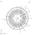
- FIG. 2 which is a cross-sectional view taken along line II-II in FIG.
- One end of the shaft 11 shown in FIG. 1 near the second bracket 18 is connected to the axle of the railway vehicle via a joint and a gear (not shown). The rotation of the shaft 11 generates the propulsion force of the railway vehicle.
- the rotor 12 has a rotor core 31 attached to the shaft 11 and a pair of sandwiching members 32 that sandwich and fix the rotor core 31 in the extending direction of the rotation axis AX.
- the rotor core 31 has a plurality of salient poles 31a, as shown in FIG.
- the salient poles are portions of the rotor core 31 that have a magnetic resistance lower than that of other portions and that guide the magnetic flux generated when the stator 13 is energized.
- the rotor core 31 is provided with a plurality of slits 31b penetrating in the extending direction of the rotation axis AX and curved convexly toward the center in the radial direction. formed side by side. Specifically, six slits 31b are arranged in the circumferential direction around the rotation axis AX and four slits 31b are formed in the radial direction. The circumferential length of the radially inner slit 31b is shorter than the circumferential length of the radially outer slit 31b.
- a salient pole 31a is formed in the vicinity of the portion where the slit 31b extends radially inward, specifically, in the vicinity of the portion where two circumferentially adjacent slits 31b are adjacent to each other.
- the salient pole 31a is formed at a portion sandwiched between two slits 31b adjacent to each other in the circumferential direction.
- the rotor 12 has six salient poles 31a by forming six slits 31b side by side in the circumferential direction. In other words, the rotor 12 has six poles.
- a magnetic path 31c connecting two adjacent salient poles 31a is formed between the slits 31b in the radial direction.
- the rotor core 31 is formed by laminating disk-shaped electromagnetic steel sheets in which through holes corresponding to the plurality of slits 31b shown in FIG. 2 and through holes through which the shaft 11 is inserted are formed.
- each electromagnetic steel plate is formed with a plurality of curved through holes protruding toward the center of the disk and a circular through hole positioned at the center.
- the curved through-hole of each electromagnetic steel sheet forms the slit 31b.
- the pair of holding members 32 shown in FIG. 1 are plate-like members whose cross-sectional shape perpendicular to the extending direction of the rotation axis AX is circular.
- the stator 13 has a stator core 33 attached to the inner peripheral surface of the frame 16 and a plurality of stator coils 34 inserted into a plurality of slots 33 a formed in the stator core 33 .
- the stator core 33 is radially opposed to the rotor core 31 with the air gap 30 interposed therebetween.
- the stator core 33 is formed with a plurality of slots 33a extending in the extending direction of the rotation axis AX.
- the stator core 33 is formed by laminating annular electromagnetic steel sheets having notches corresponding to the plurality of slots 33a.
- the slot 33 a has a shape that opens toward the rotor 12 .
- the slot 33a is a groove that has a rectangular cross-sectional shape perpendicular to the rotation axis AX, penetrates the stator core 33 in the extension direction of the rotation axis AX, and is open radially inward.
- 36 slots 33a are formed at regular intervals in the circumferential direction.
- a stator coil 34 is inserted into each slot 33a.
- a three-phase AC current is supplied from the outside to the stator coils 34 inserted into the slots 33a described above via lead wires (not shown).
- each magnetic wedge 19 is formed of a member having a shape and a material capable of suppressing an increase in magnetic permeance variation while blocking the slot 33a to prevent the stator coil 34 from coming off.
- each magnetic wedge 19 is formed of a plate-shaped ferromagnetic material, specifically, plate-shaped iron, or the same material as the electromagnetic steel plate forming the stator core 33 .
- the radial thickness of the magnetic wedge 19 is preferably a thickness capable of suppressing fluctuations in magnetic permeance caused by the formation of the slots 33 a , for example, 1/2 or more of the radial length of the air gap 30 .
- the radial thickness of the magnetic wedge 19 is preferably 1 mm or more and 4 mm or less.
- the magnetic wedge 19 preferably has a curved shape protruding radially outward, and the inner peripheral surface thereof is on the same curved surface as the inner peripheral surface of the stator core 33 .
- the openings of all the slots 33a are blocked by the magnetic wedges 19.
- a magnetic wedge 19 fits into the opening of each slot 33a.
- variations in the magnetic resistance of the inner peripheral surface of the stator 13 are smaller than when the openings of the slots 33a are not blocked. Therefore, it is possible to reduce the fluctuation of the magnetic permeance of the stator 13 .
- the magnetic wedge 19 is fitted into the opening of each slot 33a to prevent the stator coil 34 inserted into each slot 33a from coming off.
- each magnetic wedge 19 has a thin plate shape.
- the shape of the magnetic wedges 19 is determined according to the shape of the opening of each slot 33a and the amplitude of the harmonic magnetic flux that would occur in the stator 13 without the magnetic wedges 19.
- FIG. More specifically, the magnetic wedge 19 may have a shape that tightly fits into the opening of the slot 33a to such an extent that it is prevented from coming off from the opening of the slot 33a.
- the magnetic wedge 19 may have a thin plate shape in which the circumferential width of the radially outer end face matches the circumferential width of the opening of the slot 33a.
- the magnetic wedge 19 can suppress the increase in the amplitude of the harmonic flux in order to attenuate torque ripple, electromagnetic excitation forces, and harmonic losses that can be caused by the amplitude of the harmonic flux to an acceptable degree. It is sufficient to have a thin plate shape having a thickness in the radial direction of .
- the bearing 14 is held by the first bracket 17 and rotatably supports the shaft 11 .
- the bearing 15 is held by the second bracket 18 and rotatably supports the shaft 11 .
- the frame 16 is fixed under the floor of the railway vehicle by a fixing member (not shown).
- Frame 16 has a tubular shape. In Embodiment 1, frame 16 has a tubular shape with both ends open, and both ends of the tubular are closed by first bracket 17 and second bracket 18 .
- the horizontal axis of FIG. 4 represents the ratio of the radial thickness W1 of the magnetic wedge 19 to the radial length G1 of the air gap 30, that is, the radial thickness W1 of the magnetic wedge 19 is divided by the radial length G1 of the air gap 30. indicates the value obtained by dividing by .
- a value of 0 on the horizontal axis of FIG. 4 indicates a synchronous reluctance motor in which the stator slots are not blocked by magnetic wedges.
- the vertical axis in FIG. 4 indicates the loss of the rotor 12. Specifically, the vertical axis of FIG. Indicates degree. As shown in FIG. 4 , the loss of the rotor 12 can be reduced by increasing the ratio of the radial thickness W1 of the magnetic wedges 19 to the radial length G1 of the air gap 30 . By reducing the loss of the rotor 12, the amount of heat generated by the rotor 12 is reduced. As a result, it becomes possible to suppress the temperature rise of the bearings 14 and 15 that rotatably support the shaft 11 to which the rotor 12 is attached. In other words, it is possible to increase the output of the synchronous reluctance motor 1 while maintaining the temperature of the bearings 14 and 15 below the allowable temperature.
- the slots 33 a formed in the stator core 33 of the stator 13 of the synchronous reluctance motor 1 according to Embodiment 1 are blocked by the magnetic wedges 19 .
- the opening of the slot 33a is closed by the magnetic wedge 19 made of a ferromagnetic material, so that the fluctuation of the magnetic resistance of the inner peripheral surface of the stator 13 is reduced.
- torque ripple, electromagnetic excitation force, and harmonic loss can be reduced.
- the synchronous reluctance motor 1 can reduce fluctuations in magnetic permeance by closing the slots 33a of the stator core 33 with the magnetic wedges 19; , the air gap 30 between the rotor 12 and the stator 13 can be made narrower while maintaining the fluctuation of the magnetic permeance to the same extent.
- the air gap 30 has a radial length of less than 10 millimeters, specifically 2 millimeters.
- the number of slots 33a is increased while the variation in magnetic permeance is maintained at the same level to arrange the stator coils 34 in the circumferential direction. It is possible to narrow the interval. By narrowing the arrangement intervals of the stator coils 34 in the circumferential direction, the rotor 12 can be easily rotated, and the efficiency of the synchronous reluctance motor 1 is improved.
- the gap 30 between the rotor 12 and the stator 13 can be made narrower, or the circumferential spacing of the stator coils 34 can be increased without increasing the current flowing through the stator coils 34.
- the efficiency of the synchronous reluctance motor 1 can be improved.
- Embodiment 2 In the synchronous reluctance motor 1 according to Embodiment 1, the openings of all slots 33a are closed with magnetic wedges 19, but the number of magnetic wedges 19 may be less than the number of slots 33a. A synchronous reluctance motor in which the number of magnetic wedges 19 is less than the number of slots 33a will be described in a second embodiment.
- FIG. 5 is a view of the synchronous reluctance motor 2 in the same section as in FIG.
- the non-magnetic wedge 20 is made of a non-magnetic material, specifically, a material that can be regarded as having a relative magnetic permeability of 1, such as aluminum.
- the nonmagnetic wedge 20 may have the same shape as the magnetic wedge 19 .
- the present disclosure is not limited to the above embodiments.
- the rotor core 31 may have any shape as long as it allows the rotor 12 to have a plurality of salient poles 31a.
- the shape of the rotor core 31 in the cross section orthogonal to the extending direction of the rotation axis AX may not be circular.
- a plurality of projections 31d protruding radially outward may be formed on the outer peripheral surface of the rotor core 31 so as to be arranged in the circumferential direction.
- a salient pole 31a is formed on the projection 31d.
- the rotor core 31 of the rotor 12 of the synchronous reluctance motor 3 is formed by, for example, forming a plurality of curved through holes projecting toward the center of the disc in a disc-shaped electromagnetic steel plate. It is formed by forming a curved notch projecting from the outer edge toward the center of the disk and laminating electromagnetic steel sheets.
- the slits 31b may not be formed, and only projections 31d may be formed. Even in this case, the plurality of salient poles 31a of the rotor 12 are formed by the projections 31d.
- the number of poles of the rotor 12 is not limited to the above example.
- the number of poles is not limited to 6 and may be any even number.
- the rotor core 31 may be formed with four slits 31b in the circumferential direction and four slits 31b in the radial direction.
- the number of poles of the rotor 12 in this case is four.
- the ratio of the number of magnetic wedges 19 to the number of slots 33a is not limited to 1 or 1/2 as in the above embodiment. good.
- k 1 in the formula k/n representing the ratio of the number of magnetic wedges 19 to the number of slots 33a.
- 12 magnetic wedges 19 corresponding to 1/3 of 36 may be provided at regular intervals in the circumferential direction.
- one magnetic wedge 19 and two adjacent non-magnetic wedges 20 may be alternately arranged in the circumferential direction.
- the ratio of the number of magnetic wedges 19 to the number of slots 33a in the synchronous reluctance motor 2 may be 2/3.
- 24 magnetic wedges 19 corresponding to 2/3 of 36 magnetic wedges 19 may be provided at regular intervals in the circumferential direction for every two magnetic wedges 19 adjacent to each other.
- two magnetic wedges 19 and one non-magnetic wedge 20 adjacent to each other may be arranged alternately in the circumferential direction.
- the horizontal axis of FIG. 7 indicates the ratio k/n of the number of magnetic wedges 19 to the number of slots 33a.
- a value of 0 on the horizontal axis of FIG. 7 indicates a synchronous reluctance motor in which the stator slots are not blocked by magnetic wedges. If the value of the horizontal axis in FIG. 7 is greater than 0 and less than 1, it indicates a synchronous reluctance motor 2 in which magnetic wedges 19 are provided in some of the slots 33a.
- a value of 1 on the horizontal axis of FIG. 7 indicates a synchronous reluctance motor 1 in which magnetic wedges 19 are provided in all slots 33a.
- the vertical axis in FIG. 7 shows the loss of the synchronous reluctance motors 1 and 2. Specifically, the vertical axis in FIG. 7 indicates the degree of loss of the synchronous reluctance motors 1 and 2, with the loss of the synchronous reluctance motor whose stator slots are not blocked by magnetic wedges being 1. As shown in FIG. 7, even when the magnetic wedges 19 are provided only in part of the slots 33a, the loss can be reduced compared to the synchronous reluctance motor in which the slots of the stator are not blocked by the magnetic wedges. Become.
- the number of phases of the stator 13 is not limited to the above example.
- the shape of the slits 31b is not limited to the above example, and may be any shape that allows the rotor 12 to have the salient poles 31a.
- the number of slots 33a is not limited to the above example, and may be any even number.
- the number of slots may be 54.
- the shape of the slots 33a is not limited to the above example, and any shape that allows the stator coils 34 to be inserted can be used.
- the slot 33a may have a shape in which the width in the circumferential direction narrows toward the radially inner side.
- the synchronous reluctance motor 1-3 is applicable not only to electric motors for generating propulsion force for railway vehicles, but also to general-purpose electric motors such as electric motors for driving pumps.
- the synchronous reluctance motor 1-3 is not limited to an inner rotor type motor and can be applied to an outer rotor type motor.
Landscapes
- Engineering & Computer Science (AREA)
- Power Engineering (AREA)
- Insulation, Fastening Of Motor, Generator Windings (AREA)
- Iron Core Of Rotating Electric Machines (AREA)
- Synchronous Machinery (AREA)
Abstract
Description
鉄道車両を駆動するための同期リラクタンスモータを用いて、実施の形態1に係る同期リラクタンスモータ1について説明する。図1に示す同期リラクタンスモータ1は、鉄道車両の床下に取り付けられる。図1において、Z軸方向は、鉄道車両が水平に位置している状態で鉛直方向を示す。Y軸方向は、鉄道車両の幅方向を示す。X軸方向は、鉄道車両の進行方向を示す。換言すれば、鉄道車両は、X軸正方向またはX軸負方向に進む。X軸、Y軸、およびZ軸は互いに直交する。
図1に示すシャフト11の第2ブラケット18に近い一端は、図示しない継手および歯車を介して鉄道車両の車軸に連結されている。シャフト11が回転することで、鉄道車両の推進力が発生する。
軸受15は、第2ブラケット18に保持されて、シャフト11を回転可能に支持する。
フレーム16は、図示しない固定部材によって鉄道車両の床下に固定される。フレーム16は、筒状の形状を有する。実施の形態1では、フレーム16は、両端が開口している筒の形状を有し、筒の両端が第1ブラケット17および第2ブラケット18に塞がれる。
実施の形態1に係る同期リラクタンスモータ1では、全てのスロット33aの開口が磁性楔19で塞がれているが、磁性楔19の個数はスロット33aの個数より少なくてもよい。磁性楔19の個数がスロット33aの個数より少ない同期リラクタンスモータについて実施の形態2で説明する。
スロット33aの形状は、上述の例に限られず、固定子コイル34を挿入可能な形状であれば任意である。一例として、スロット33aは、周方向の幅が径方向内側に近づくにつれて狭くなる形状でもよい。
同期リラクタンスモータ1-3は、インナーロータ型のモータに限られず、アウターロータ型のモータに適用可能である。
Claims (9)
- 回転軸周りに回転可能に支持されるシャフトと、
前記シャフトの径方向の外側に位置して前記シャフトと一体に回転し、複数の突極を有する回転子と、
前記回転子と空隙を挟んで前記径方向に対向し、前記回転子に向いて開口している複数のスロットが前記回転軸周りの周方向に並んで形成される固定子鉄心と、前記複数のスロットに挿入される複数の固定子コイルと、を有する固定子と、
前記複数のスロットの少なくとも一部について、前記固定子コイルが挿入された状態で前記スロットを塞ぐ複数の磁性楔と、
を備える同期リラクタンスモータ。 - 前記複数の磁性楔の個数は、前記複数のスロットの個数に一致する、
請求項1に記載の同期リラクタンスモータ。 - 前記複数の磁性楔の個数は、前記回転子の極数と前記固定子の相数との積の倍数であって、前記複数のスロットの個数よりも少ない、
請求項1に記載の同期リラクタンスモータ。 - 前記複数の磁性楔は、前記周方向に等間隔で設けられる、
請求項3に記載の同期リラクタンスモータ。 - 前記複数の磁性楔は、互いに隣接する2つ以上の前記磁性楔ごとに前記周方向に等間隔で設けられる、
請求項3に記載の同期リラクタンスモータ。 - 前記複数のスロットの内、前記磁性楔で塞がれていない前記スロットについて、前記固定子コイルが挿入された状態で前記スロットを塞ぐ非磁性楔をさらに備える、
請求項3から5のいずれか1項に記載の同期リラクタンスモータ。 - 前記磁性楔の径方向の厚みは、前記固定子と前記回転子との間の前記空隙の径方向の長さより長い、
請求項1から6のいずれか1項に記載の同期リラクタンスモータ。 - 前記回転子には、前記回転軸の延伸方向に貫通し前記径方向の中心に向かって凸に湾曲する複数のスリットが、前記周方向に並んで形成され、
前記突極は、前記周方向に互いに隣接する前記スリットに挟まれた部位に形成される、
請求項1から7のいずれか1項に記載の同期リラクタンスモータ。 - 前記回転子には、外周面に前記径方向の外方に突出する複数の突起が、前記周方向に並んで形成され、
前記突極は、前記突起に形成される、
請求項1から8のいずれか1項に記載の同期リラクタンスモータ。
Priority Applications (4)
| Application Number | Priority Date | Filing Date | Title |
|---|---|---|---|
| US18/261,532 US20240072594A1 (en) | 2021-03-24 | 2021-03-24 | Synchronous reluctance motor |
| JP2023508288A JP7422940B2 (ja) | 2021-03-24 | 2021-03-24 | 同期リラクタンスモータ |
| PCT/JP2021/012387 WO2022201396A1 (ja) | 2021-03-24 | 2021-03-24 | 同期リラクタンスモータ |
| DE112021007358.3T DE112021007358T5 (de) | 2021-03-24 | 2021-03-24 | Synchron-reluktanzmotor |
Applications Claiming Priority (1)
| Application Number | Priority Date | Filing Date | Title |
|---|---|---|---|
| PCT/JP2021/012387 WO2022201396A1 (ja) | 2021-03-24 | 2021-03-24 | 同期リラクタンスモータ |
Publications (1)
| Publication Number | Publication Date |
|---|---|
| WO2022201396A1 true WO2022201396A1 (ja) | 2022-09-29 |
Family
ID=83395392
Family Applications (1)
| Application Number | Title | Priority Date | Filing Date |
|---|---|---|---|
| PCT/JP2021/012387 Ceased WO2022201396A1 (ja) | 2021-03-24 | 2021-03-24 | 同期リラクタンスモータ |
Country Status (4)
| Country | Link |
|---|---|
| US (1) | US20240072594A1 (ja) |
| JP (1) | JP7422940B2 (ja) |
| DE (1) | DE112021007358T5 (ja) |
| WO (1) | WO2022201396A1 (ja) |
Families Citing this family (2)
| Publication number | Priority date | Publication date | Assignee | Title |
|---|---|---|---|---|
| IT202000006052A1 (it) * | 2020-03-23 | 2021-09-23 | Motovario S P A | Motore a riluttanza autoavviante. |
| CN115917926A (zh) * | 2020-05-29 | 2023-04-04 | 三菱电机株式会社 | 电磁设备以及使用电磁设备的飞机 |
Citations (4)
| Publication number | Priority date | Publication date | Assignee | Title |
|---|---|---|---|---|
| JPS6387146A (ja) * | 1986-09-29 | 1988-04-18 | Hitachi Ltd | 分割固定子を用いた回転電機 |
| JPS6434147A (en) * | 1987-07-28 | 1989-02-03 | Olympus Optical Co | Armature for rotary electric machine |
| JP2002199675A (ja) * | 2000-12-21 | 2002-07-12 | Hitachi Ltd | 同期リラクタンスモータ |
| JP2010136537A (ja) * | 2008-12-05 | 2010-06-17 | Hitachi Automotive Systems Ltd | 回転電機およびその製造方法 |
Family Cites Families (7)
| Publication number | Priority date | Publication date | Assignee | Title |
|---|---|---|---|---|
| US4539499A (en) * | 1984-01-03 | 1985-09-03 | Punch William E | Device for detection of contact between rotor and stator |
| JPH0522885A (ja) * | 1991-07-08 | 1993-01-29 | Hitachi Ltd | 回転電機の磁性楔 |
| JPH08172742A (ja) * | 1994-12-19 | 1996-07-02 | Toshiba Corp | 永久磁石界磁方式回転電機 |
| US5877572A (en) * | 1996-10-01 | 1999-03-02 | Emerson Electric Co. | Reduced noise reluctance machine |
| WO2002043223A2 (en) * | 2000-11-27 | 2002-05-30 | S.H.R. Limited Bvi | Fastening arrangements for windings of elecctric machines |
| US9231504B2 (en) * | 2012-05-15 | 2016-01-05 | Robert Lyle Fuller | Electrical control system |
| WO2018079151A1 (ja) * | 2016-10-31 | 2018-05-03 | アイシン・エィ・ダブリュ株式会社 | ステータおよびステータの製造方法 |
-
2021
- 2021-03-24 US US18/261,532 patent/US20240072594A1/en active Pending
- 2021-03-24 JP JP2023508288A patent/JP7422940B2/ja active Active
- 2021-03-24 WO PCT/JP2021/012387 patent/WO2022201396A1/ja not_active Ceased
- 2021-03-24 DE DE112021007358.3T patent/DE112021007358T5/de active Pending
Patent Citations (4)
| Publication number | Priority date | Publication date | Assignee | Title |
|---|---|---|---|---|
| JPS6387146A (ja) * | 1986-09-29 | 1988-04-18 | Hitachi Ltd | 分割固定子を用いた回転電機 |
| JPS6434147A (en) * | 1987-07-28 | 1989-02-03 | Olympus Optical Co | Armature for rotary electric machine |
| JP2002199675A (ja) * | 2000-12-21 | 2002-07-12 | Hitachi Ltd | 同期リラクタンスモータ |
| JP2010136537A (ja) * | 2008-12-05 | 2010-06-17 | Hitachi Automotive Systems Ltd | 回転電機およびその製造方法 |
Also Published As
| Publication number | Publication date |
|---|---|
| JPWO2022201396A1 (ja) | 2022-09-29 |
| DE112021007358T5 (de) | 2024-02-15 |
| US20240072594A1 (en) | 2024-02-29 |
| JP7422940B2 (ja) | 2024-01-26 |
Similar Documents
| Publication | Publication Date | Title |
|---|---|---|
| US7705503B2 (en) | Rotating electrical machine | |
| CN103872869B (zh) | 多间隙式旋转电机 | |
| JP6671553B1 (ja) | 回転電機 | |
| JP5159228B2 (ja) | 磁気誘導子形同期回転機およびそれを用いた自動車用過給機 | |
| CN101981785A (zh) | 旋转电机 | |
| JPH0739091A (ja) | 同期機のロータ構造および同期型モータ | |
| US12057749B2 (en) | Stator assembly flux alignment | |
| JP6048191B2 (ja) | マルチギャップ型回転電機 | |
| JP6025998B2 (ja) | 磁気誘導子型電動機 | |
| JP7422940B2 (ja) | 同期リラクタンスモータ | |
| JP5259927B2 (ja) | 永久磁石式回転電機 | |
| JP2009050148A (ja) | 広範囲定出力永久磁石式モータ | |
| JP5439904B2 (ja) | 回転電機 | |
| JP6760014B2 (ja) | 回転電機 | |
| JP5390752B2 (ja) | 埋め込み磁石モータ | |
| JPH09266646A (ja) | ブラシレスdcモータ | |
| JP7132729B2 (ja) | 回転電機 | |
| JP5151183B2 (ja) | アキシャルギャップ型回転電機及び圧縮機 | |
| JP7455994B2 (ja) | 回転電機 | |
| JP6857514B2 (ja) | 回転電機のステータ | |
| US7053518B2 (en) | Rotor for dynamo-electric machine | |
| JP5129034B2 (ja) | 交流励磁回転電機 | |
| JP5679695B2 (ja) | 永久磁石式回転電機 | |
| JP3161176B2 (ja) | 同期機のロータ構造および同期モータ | |
| CN116941169A (zh) | 磁性齿轮传动旋转机械、发电系统及磁极片转子 |
Legal Events
| Date | Code | Title | Description |
|---|---|---|---|
| 121 | Ep: the epo has been informed by wipo that ep was designated in this application |
Ref document number: 21933006 Country of ref document: EP Kind code of ref document: A1 |
|
| ENP | Entry into the national phase |
Ref document number: 2023508288 Country of ref document: JP Kind code of ref document: A |
|
| WWE | Wipo information: entry into national phase |
Ref document number: 18261532 Country of ref document: US |
|
| WWE | Wipo information: entry into national phase |
Ref document number: 202327058715 Country of ref document: IN |
|
| WWE | Wipo information: entry into national phase |
Ref document number: 112021007358 Country of ref document: DE |
|
| 122 | Ep: pct application non-entry in european phase |
Ref document number: 21933006 Country of ref document: EP Kind code of ref document: A1 |