WO2022201258A1 - 半導体装置の製造方法、表示方法、基板処理装置およびプログラム - Google Patents
半導体装置の製造方法、表示方法、基板処理装置およびプログラム Download PDFInfo
- Publication number
- WO2022201258A1 WO2022201258A1 PCT/JP2021/011786 JP2021011786W WO2022201258A1 WO 2022201258 A1 WO2022201258 A1 WO 2022201258A1 JP 2021011786 W JP2021011786 W JP 2021011786W WO 2022201258 A1 WO2022201258 A1 WO 2022201258A1
- Authority
- WO
- WIPO (PCT)
- Prior art keywords
- recipe
- flow rate
- valve
- gas
- screen
- Prior art date
- Legal status (The legal status is an assumption and is not a legal conclusion. Google has not performed a legal analysis and makes no representation as to the accuracy of the status listed.)
- Ceased
Links
Images





Classifications
-
- H—ELECTRICITY
- H10—SEMICONDUCTOR DEVICES; ELECTRIC SOLID-STATE DEVICES NOT OTHERWISE PROVIDED FOR
- H10P—GENERIC PROCESSES OR APPARATUS FOR THE MANUFACTURE OR TREATMENT OF DEVICES COVERED BY CLASS H10
- H10P14/00—Formation of materials, e.g. in the shape of layers or pillars
- H10P14/60—Formation of materials, e.g. in the shape of layers or pillars of insulating materials
-
- H—ELECTRICITY
- H10—SEMICONDUCTOR DEVICES; ELECTRIC SOLID-STATE DEVICES NOT OTHERWISE PROVIDED FOR
- H10P—GENERIC PROCESSES OR APPARATUS FOR THE MANUFACTURE OR TREATMENT OF DEVICES COVERED BY CLASS H10
- H10P72/00—Handling or holding of wafers, substrates or devices during manufacture or treatment thereof
- H10P72/06—Apparatus for monitoring, sorting, marking, testing or measuring
- H10P72/0604—Process monitoring, e.g. flow or thickness monitoring
-
- H—ELECTRICITY
- H10—SEMICONDUCTOR DEVICES; ELECTRIC SOLID-STATE DEVICES NOT OTHERWISE PROVIDED FOR
- H10P—GENERIC PROCESSES OR APPARATUS FOR THE MANUFACTURE OR TREATMENT OF DEVICES COVERED BY CLASS H10
- H10P72/00—Handling or holding of wafers, substrates or devices during manufacture or treatment thereof
- H10P72/04—Apparatus for manufacture or treatment
- H10P72/0402—Apparatus for fluid treatment
-
- C—CHEMISTRY; METALLURGY
- C23—COATING METALLIC MATERIAL; COATING MATERIAL WITH METALLIC MATERIAL; CHEMICAL SURFACE TREATMENT; DIFFUSION TREATMENT OF METALLIC MATERIAL; COATING BY VACUUM EVAPORATION, BY SPUTTERING, BY ION IMPLANTATION OR BY CHEMICAL VAPOUR DEPOSITION, IN GENERAL; INHIBITING CORROSION OF METALLIC MATERIAL OR INCRUSTATION IN GENERAL
- C23C—COATING METALLIC MATERIAL; COATING MATERIAL WITH METALLIC MATERIAL; SURFACE TREATMENT OF METALLIC MATERIAL BY DIFFUSION INTO THE SURFACE, BY CHEMICAL CONVERSION OR SUBSTITUTION; COATING BY VACUUM EVAPORATION, BY SPUTTERING, BY ION IMPLANTATION OR BY CHEMICAL VAPOUR DEPOSITION, IN GENERAL
- C23C16/00—Chemical coating by decomposition of gaseous compounds, without leaving reaction products of surface material in the coating, i.e. chemical vapour deposition [CVD] processes
- C23C16/44—Chemical coating by decomposition of gaseous compounds, without leaving reaction products of surface material in the coating, i.e. chemical vapour deposition [CVD] processes characterised by the method of coating
- C23C16/455—Chemical coating by decomposition of gaseous compounds, without leaving reaction products of surface material in the coating, i.e. chemical vapour deposition [CVD] processes characterised by the method of coating characterised by the method used for introducing gases into reaction chamber or for modifying gas flows in reaction chamber
- C23C16/45523—Pulsed gas flow or change of composition over time
- C23C16/45525—Atomic layer deposition [ALD]
- C23C16/45544—Atomic layer deposition [ALD] characterized by the apparatus
- C23C16/45546—Atomic layer deposition [ALD] characterized by the apparatus specially adapted for a substrate stack in the ALD reactor
-
- C—CHEMISTRY; METALLURGY
- C23—COATING METALLIC MATERIAL; COATING MATERIAL WITH METALLIC MATERIAL; CHEMICAL SURFACE TREATMENT; DIFFUSION TREATMENT OF METALLIC MATERIAL; COATING BY VACUUM EVAPORATION, BY SPUTTERING, BY ION IMPLANTATION OR BY CHEMICAL VAPOUR DEPOSITION, IN GENERAL; INHIBITING CORROSION OF METALLIC MATERIAL OR INCRUSTATION IN GENERAL
- C23C—COATING METALLIC MATERIAL; COATING MATERIAL WITH METALLIC MATERIAL; SURFACE TREATMENT OF METALLIC MATERIAL BY DIFFUSION INTO THE SURFACE, BY CHEMICAL CONVERSION OR SUBSTITUTION; COATING BY VACUUM EVAPORATION, BY SPUTTERING, BY ION IMPLANTATION OR BY CHEMICAL VAPOUR DEPOSITION, IN GENERAL
- C23C16/00—Chemical coating by decomposition of gaseous compounds, without leaving reaction products of surface material in the coating, i.e. chemical vapour deposition [CVD] processes
- C23C16/44—Chemical coating by decomposition of gaseous compounds, without leaving reaction products of surface material in the coating, i.e. chemical vapour deposition [CVD] processes characterised by the method of coating
- C23C16/52—Controlling or regulating the coating process
-
- G—PHYSICS
- G05—CONTROLLING; REGULATING
- G05B—CONTROL OR REGULATING SYSTEMS IN GENERAL; FUNCTIONAL ELEMENTS OF SUCH SYSTEMS; MONITORING OR TESTING ARRANGEMENTS FOR SUCH SYSTEMS OR ELEMENTS
- G05B19/00—Program-control systems
- G05B19/02—Program-control systems electric
- G05B19/18—Numerical control [NC], i.e. automatically operating machines, in particular machine tools, e.g. in a manufacturing environment, so as to execute positioning, movement or co-ordinated operations by means of program data in numerical form
- G05B19/4097—Numerical control [NC], i.e. automatically operating machines, in particular machine tools, e.g. in a manufacturing environment, so as to execute positioning, movement or co-ordinated operations by means of program data in numerical form characterised by using design data to control NC machines, e.g. CAD/CAM
- G05B19/4099—Surface or curve machining, making three-dimensional [3D] objects, e.g. desktop manufacturing
-
- G—PHYSICS
- G05—CONTROLLING; REGULATING
- G05B—CONTROL OR REGULATING SYSTEMS IN GENERAL; FUNCTIONAL ELEMENTS OF SUCH SYSTEMS; MONITORING OR TESTING ARRANGEMENTS FOR SUCH SYSTEMS OR ELEMENTS
- G05B19/00—Program-control systems
- G05B19/02—Program-control systems electric
- G05B19/418—Total factory control, i.e. centrally controlling a plurality of machines, e.g. direct or distributed numerical control [DNC], flexible manufacturing systems [FMS], integrated manufacturing systems [IMS] or computer integrated manufacturing [CIM]
-
- G—PHYSICS
- G06—COMPUTING OR CALCULATING; COUNTING
- G06F—ELECTRIC DIGITAL DATA PROCESSING
- G06F3/00—Input arrangements for transferring data to be processed into a form capable of being handled by the computer; Output arrangements for transferring data from processing unit to output unit, e.g. interface arrangements
- G06F3/01—Input arrangements or combined input and output arrangements for interaction between user and computer
- G06F3/048—Interaction techniques based on graphical user interfaces [GUI]
- G06F3/0481—Interaction techniques based on graphical user interfaces [GUI] based on specific properties of the displayed interaction object or a metaphor-based environment, e.g. interaction with desktop elements like windows or icons, or assisted by a cursor's changing behaviour or appearance
- G06F3/04817—Interaction techniques based on graphical user interfaces [GUI] based on specific properties of the displayed interaction object or a metaphor-based environment, e.g. interaction with desktop elements like windows or icons, or assisted by a cursor's changing behaviour or appearance using icons
-
- G—PHYSICS
- G06—COMPUTING OR CALCULATING; COUNTING
- G06F—ELECTRIC DIGITAL DATA PROCESSING
- G06F3/00—Input arrangements for transferring data to be processed into a form capable of being handled by the computer; Output arrangements for transferring data from processing unit to output unit, e.g. interface arrangements
- G06F3/14—Digital output to display device ; Cooperation and interconnection of the display device with other functional units
-
- G—PHYSICS
- G08—SIGNALLING
- G08B—SIGNALLING SYSTEMS, e.g. PERSONAL CALLING SYSTEMS; ORDER TELEGRAPHS; ALARM SYSTEMS
- G08B21/00—Alarms responsive to a single specified undesired or abnormal condition and not otherwise provided for
- G08B21/18—Status alarms
-
- G—PHYSICS
- G05—CONTROLLING; REGULATING
- G05B—CONTROL OR REGULATING SYSTEMS IN GENERAL; FUNCTIONAL ELEMENTS OF SUCH SYSTEMS; MONITORING OR TESTING ARRANGEMENTS FOR SUCH SYSTEMS OR ELEMENTS
- G05B2219/00—Program-control systems
- G05B2219/30—Nc systems
- G05B2219/31—From computer integrated manufacturing till monitoring
- G05B2219/31103—Configure parameters of controlled devices
-
- G—PHYSICS
- G05—CONTROLLING; REGULATING
- G05B—CONTROL OR REGULATING SYSTEMS IN GENERAL; FUNCTIONAL ELEMENTS OF SUCH SYSTEMS; MONITORING OR TESTING ARRANGEMENTS FOR SUCH SYSTEMS OR ELEMENTS
- G05B2219/00—Program-control systems
- G05B2219/30—Nc systems
- G05B2219/45—Nc applications
- G05B2219/45031—Manufacturing semiconductor wafers
Definitions
- the present disclosure relates to a semiconductor device manufacturing method, a display method, a substrate processing apparatus, and a program.
- a substrate processing apparatus includes a plurality of gas lines for supplying various gases such as raw material gas, inert gas, and reaction gas into the processing chamber. 2. Description of the Related Art In a substrate processing apparatus, predetermined processing is performed by opening and closing valves of gas lines to supply various gases from a gas supply system to a substrate (hereinafter also referred to as a wafer) in a processing chamber.
- Patent Document 1 describes a substrate processing method for creating a recipe by collectively displaying an area for setting control parameters, an area for setting valve opening/closing states, and an area for displaying various parameter information on a recipe editing screen. An apparatus is disclosed.
- Patent Document 2 discloses that a recipe editing screen has a recipe editing area for editing steps of a recipe file, a sub-area for displaying a combination file associated with a recipe, and a recipe editing command for selecting a recipe editing command and performing an actual editing action. Also disclosed is a processing apparatus that creates a recipe by collectively displaying command selection areas such as
- Patent Literature 3 discloses a substrate processing apparatus in which the display can be switched from the recipe edit screen to the gas pattern screen and valve opening/closing settings can be made.
- a technology is provided that allows the user to confirm which gas line has the gas flow rate that the user is trying to set.
- a parameter setting area for setting control parameters including at least the gas flow rate of the flow controller and the open/closed state of the valve are set.
- displaying a gas pattern screen Editing a recipe on the recipe editing screen; processing the substrate by executing the edited recipe; has
- the step of editing the recipe when the gas flow rate of the flow rate controller is set in the parameter setting area, the flow rate controller on the gas pattern screen corresponding to the flow rate controller for which the gas flow rate is set is changed.
- FIG. 1 is a vertical cross-sectional view of a processing furnace 202 of a substrate processing apparatus 10 preferably used in one embodiment of the present disclosure
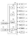
- FIG. 1 is a schematic configuration diagram of a controller 240 of a substrate processing apparatus 10 preferably used in an embodiment of the present disclosure, and is a block diagram showing a control system of the controller
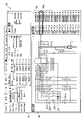
- FIG. It is a display example of the recipe edit screen 20 displayed when editing a recipe.
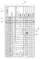
- 4 is an enlarged view of a step setting area 30 of the recipe edit screen 20 shown in FIG. 3
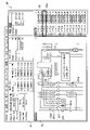
- FIG. 4 is an enlarged view of a step content setting area 40 of the recipe editing screen 20 shown in FIG. 3
- FIG. 11 is a diagram showing a display example of a warning display when a valve interlock condition is met when the valve 243a is set to be open on the gas pattern screen 42;
- FIG. 11 is a diagram showing a display example of valve interlock conditions when a valve for which valve interlock conditions are set is long-pressed on the gas pattern screen 42;
- FIG. 11 is a diagram showing a display example of a warning display when a valve interlock condition is met when the valve 243a is set to be open on the gas pattern screen 42;
- FIG. 11 is a diagram showing a display example of valve interlock conditions when a valve for which valve interlock conditions are set is long-pressed on the gas pattern screen 42;
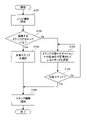
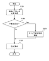
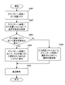
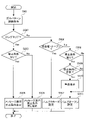
- 10 is a diagram showing a display example when an arbitrary valve is selected on the gas pattern screen 42 and a gas pipe connected to the selected valve is specified; 4 is a flowchart for explaining the flow at the start of recipe editing in the substrate processing apparatus 10 of one embodiment of the present disclosure; 4 is a flowchart for explaining the flow of gas setting in the substrate processing apparatus 10 according to the embodiment of the present disclosure; 4 is a flowchart for explaining processing when settings are changed in a parameter setting area 41 or a gas pattern screen 42 on a recipe editing screen 20 in the substrate processing apparatus 10 of one embodiment of the present disclosure; 4 is a flowchart for explaining processing when displaying MFCs in association with each other in a parameter setting area 41 and a gas pattern screen 42 on a recipe editing screen 20 in the substrate processing apparatus 10 of the embodiment of the present disclosure; 4 is a flowchart for explaining processing when an arbitrary valve is selected on a gas pattern screen 42 on a recipe editing screen 20 in the substrate processing apparatus 10 of one embodiment of the present disclosure; 4 is a flowchart for
- FIG. 1 An embodiment of the present disclosure will be described below with reference to the drawings.
- a substrate processing apparatus 10 in which the present disclosure is implemented will be described with reference to FIGS. 1 and 2.
- FIG. The drawings used in the following description are all schematic, and the dimensional relationship of each element, the ratio of each element, etc. shown in the drawings do not necessarily match the actual ones. Moreover, the dimensional relationship of each element, the ratio of each element, etc. do not necessarily match between a plurality of drawings.
- the substrate processing apparatus 10 includes a processing furnace 202 for processing wafers 200 as substrates transported into a housing.
- the processing furnace 202 has a heater 207 as a heating mechanism (temperature control unit).
- the heater 207 has a cylindrical shape and is installed vertically by being supported by a holding plate.
- the heater 207 also functions as an activation mechanism (excitation section) that thermally activates (excites) the gas.
- a reaction tube 203 is arranged concentrically with the heater 207 inside the heater 207 .
- the reaction tube 203 is made of a heat-resistant material such as quartz (SiO 2 ) or silicon carbide (SiC), and has a cylindrical shape with a closed upper end and an open lower end.
- a processing chamber 201 is formed in the cylindrical hollow portion of the reaction tube 203 .
- the processing chamber 201 is configured to accommodate the wafer 200 .
- a wafer 200 is processed in this processing chamber 201 .
- a plurality of nozzles 249 are provided in the processing chamber 201 so as to penetrate the lower side wall of the reaction tube 203 .
- a plurality of gas supply pipes 232 are connected to each nozzle 249 .
- the gas supply pipe 232 is provided with a mass flow controller (MFC) 241 as a flow controller (flow control unit) and a valve 243 as an on-off valve in order from the upstream side.
- MFC mass flow controller
- various gases such as raw material gas, inert gas and reaction gas are supplied into the processing chamber 201 through the MFC 241, the valve 243 and the nozzle 249, respectively.
- An exhaust pipe 231 for exhausting the atmosphere of the processing chamber 201 is connected to the lower side wall of the reaction tube 203 .
- the exhaust pipe 231 is supplied with a pressure sensor 245 as a pressure detector (pressure detector) for detecting the pressure in the processing chamber 201 and an APC (Auto Pressure Controller) valve 244 as a pressure regulator (pressure regulator).
- an evacuation device 246 constituted by a vacuum pump is connected.
- the APC valve 244 can evacuate the processing chamber 201 and stop the evacuation by opening and closing the valve while the exhaust device 246 is in operation. By adjusting the valve opening based on the pressure information detected by the pressure sensor 245, the pressure in the processing chamber 201 can be adjusted.
- An exhaust system is mainly composed of the exhaust pipe 231 , the pressure sensor 245 and the APC valve 244 .
- the exhaust system 246 may be considered to be included in the exhaust system.
- gas supply pipe 232 and the exhaust pipe 231 may be collectively called a gas pipe.
- a seal cap 219 is provided as a furnace palate lid that can airtightly close the opening at the lower end of the reaction tube 203.
- the seal cap 219 is made of, for example, a metal material such as SUS, and is shaped like a disc.
- An O-ring 220 is provided on the upper surface of the seal cap 219 as a sealing member that contacts the lower end of the reaction tube 203 .
- a rotating mechanism 267 for rotating the boat 217 which will be described later, is installed below the seal cap 219.
- a rotating shaft 255 of the rotating mechanism 267 passes through the seal cap 219 and is connected to the boat 217 .
- the rotating mechanism 267 is configured to rotate the wafers 200 by rotating the boat 217 .
- the seal cap 219 is configured to be vertically moved up and down by a boat elevator 115 as a lifting mechanism installed outside the reaction tube 203 .
- the boat elevator 115 is configured as a transport device (transport mechanism) for loading and unloading (transporting) the wafer 200 into and out of the processing chamber 201 by raising and lowering the seal cap 219 .
- the boat 217 as a substrate support supports a plurality of wafers 200, for example, 25 to 250 wafers 200, in a horizontal posture, aligned vertically with their centers aligned with each other, and supported in multiple stages. It is configured to be spaced and arranged.
- the boat 217 is made of a heat-resistant material such as quartz or SiC.
- heat insulating plates 218 made of a heat-resistant material such as quartz or SiC are supported horizontally in multiple stages.
- a temperature sensor 263 as a temperature detector is installed in the reaction tube 203 .
- the temperature inside the processing chamber 201 has a desired temperature distribution.
- a temperature sensor 263 is provided along the inner wall of the reaction tube 203 .
- a controller 240 which is a control unit (control means), is a computer equipped with a CPU (Central Processing Unit) 240a, a RAM (Random Access Memory) 240b, a storage device 240c, and an I/O port 240d.
- the RAM 240b, storage device 240c, and I/O port 240d are configured to exchange data with the CPU 240a via an internal bus 240e.
- An input/output device 252 configured as a touch panel, for example, is connected to the controller 240 .
- the storage device 240c is composed of, for example, a flash memory, HDD (Hard Disk Drive), or the like.
- the storage device 240c stores readably a control program for controlling the operation of the substrate processing apparatus, a recipe describing predetermined processing procedures (hereinafter also referred to as steps), conditions, and the like.
- a process recipe which is mainly composed of a plurality of steps, is combined so that each step in a predetermined process can be executed by the controller 240 to obtain a predetermined result, and functions as a program.
- recipes including process recipes, control programs, etc. are collectively referred to as programs.
- the process recipe is also simply referred to as a recipe.
- program When the term "program” is used in this specification, it may include only a single recipe, only a single control program, or both.
- the RAM 240b is configured as a memory area (work area) in which programs and data read by the CPU 240a are temporarily held.
- the I/O port 240d is connected to the MFC 241, the valve 243, the pressure sensor 245, the APC valve 244, the exhaust device 246, the temperature sensor 263, the heater 207, the rotation mechanism 267, the boat elevator 115, and the like.
- the CPU 240a is configured to read and execute a control program from the storage device 240c, and to read recipes from the storage device 240c in response to input of operation commands from the input/output device 252 and the like.
- the CPU 240a adjusts the flow rate of various gases by the MFC 241, the opening/closing operation of the valve 243, the opening/closing operation of the APC valve 244, the pressure adjustment operation by the APC valve 244 based on the pressure sensor 245, and the exhaust device, in accordance with the content of the read recipe. 246, the temperature adjustment operation of the heater 207 based on the temperature sensor 263, the rotation and rotation speed adjustment operation of the boat 217 by the rotation mechanism 267, the lifting operation of the boat 217 by the boat elevator 115, and the like.
- the controller 240 can be configured by installing the above-described program stored in the external storage device 250 in the computer.
- the external storage device 250 includes, for example, a magnetic disk such as an HDD, an optical disk such as a CD, a magneto-optical disk such as an MO, a semiconductor memory such as a USB memory, and the like.
- the storage device 240c and the external storage device 250 are configured as computer-readable recording media. Hereinafter, these are also collectively referred to simply as recording media. When the term "recording medium" is used in this specification, it may include only the storage device 240c alone, may include only the external storage device 250 alone, or may include both of them.
- the program may be provided to the computer using communication means such as the Internet or a dedicated line without using the external storage device 250 .
- the substrate processing apparatus 10 of the present embodiment displays a parameter setting area for setting control parameters and a gas pattern screen including valves and gas pipes on the recipe editing screen.
- a parameter setting area for setting control parameters and a gas pattern screen including valves and gas pipes
- an icon indicating the MFC in the gas pattern screen corresponding to the MFC for which this control parameter is set is displayed.
- the recipe editing screen 20 shown in FIG. 3 includes a step setting area 30 and a step content setting area 40.
- a step setting area 30 When the user selects a step to be edited in the step setting area 30 on the left side of the drawing, the content of the selected step is displayed in the step content setting area 40 on the right side of the drawing.
- a parameter setting area 41 for setting control parameters and a gas pattern screen 42 for setting the open/close state of the valve are displayed.
- the recipe editing screen 20 is configured such that a parameter setting area 41 and a gas pattern screen 42 are displayed for each step.
- the recipe edit screen 20 also has a parameter setting area 41 to be displayed and a step setting area 30 for setting steps of the gas pattern screen 42 .
- the step setting area 30 has a two-dimensional matrix format in which steps are displayed in the vertical axis area 31 and item types are displayed in the horizontal axis area 32 .
- a selection display frame 34 is displayed to clearly indicate the currently selected step.
- the step setting area 30 is configured to display whether or not the setting of the control parameter has been changed for each step item.
- the items 33a with changes are marked with *.
- the interlock condition is a setting content that causes a problem in the substrate processing apparatus 10 .
- preset contents are stored in the external storage device 250 of the controller 240 .
- the background color of the item 33b whose control parameter is set to match the interlock condition is displayed in warning color as a warning display.
- Fig. 5 shows a state in which the "outline" tab is selected.
- the "outline” tab is a tab showing an overview of the contents of the selected step, and includes a parameter setting area 41 for setting main control parameters such as temperature, pressure, transfer, MFC, etc., and opening and closing of valves.
- a gas pattern screen 42 for setting is displayed.
- Control parameters related to "temperature” include, for example, "control mode to be used in the step”, “designation of control table”, “setting value of temperature zone”, “designation of ramp rate”, and “presence or absence of step end condition”. settings” and the like.
- Control parameters related to "pressure” include, for example, "control mode used in the step”, “designation of control table”, “designation of pressure command and setting value”, and "setting of presence/absence of step end condition”. be done.
- Control parameters related to "MFC” include, for example, “set value for each MFC", “designation of ramp rate”, “setting of presence/absence of step end condition”, and the like.
- Control parameters related to "valve” include, for example, "gas pattern editing (valve ON/OFF)".
- Control parameters related to "conveyance” include, for example, "designation of loader command” and "designation of execution conditions (for example, speed, etc.) of the loader command to be used”.
- Control parameters related to "AUX (external device)" include, for example, "designation of set values for each AUX” and "setting of presence/absence of step end conditions". Since the AUX (external device) is read-only, the controller 240 verifies whether the read value meets the conditions for the setting value.
- Control parameters related to "Signal” include, for example, "Signal ON/OFF designation”. “Signal ON/OFF designation” specifically designates ON/OFF of a specific signal to the controller 240 . Controller 240 initiates or inhibits operation in that signal state.
- Control parameters related to "Alarm” include, for example, "alarm conditions”.
- the alarm condition specifies, for example, whether to generate an alarm for each monitored value.
- On the "Alarm” tab settings in use are displayed in the form of an alarm condition table in which a plurality of alarm conditions are summarized in tabular form.
- control parameters are merely examples, and the parameters displayed on the recipe editing screen 20 can be set as appropriate depending on the recipe.
- various components such as a plurality of MFCs 241, a plurality of valves 243, a processing furnace, a vaporizer, an exhaust system, and a pressure regulator, each of which is displayed as an icon, are connected like a network. is connected by many gas pipes.
- the open/closed state which indicates whether the current valve is in an open state (open state) or a closed state (closed state). Specifically, by switching the display color of the valve depending on whether the valve is open or closed, it is possible to know whether the valve is open or closed.
- this gas pattern screen 42 is provided with an operation function for the user to switch the open/closed state of any valve, in addition to the function for monitoring the open/closed state of the valve.
- this valve operation function by tapping the image of the valve 243 displayed on the gas pattern screen 42, it is possible to switch between the open state and the closed state.
- the controller 240 displays a parameter setting area 41 for setting control parameters including at least the gas flow rate of the MFC, and a gas pattern screen 42 for setting the open/closed state of the valve on the recipe editing screen 20 for creating a recipe including a plurality of steps. , is displayed, a recipe can be created on the recipe edit screen 20 .
- the controller 240 is configured to clearly indicate the MFC on the gas pattern screen 42 corresponding to the MFC for which the gas flow rate is set when the gas flow rate of the MFC is set on the gas flow rate list 50 in the parameter setting area 41. It is The method of specifying the MFC 241 on the gas pattern screen 42 corresponding to the MFC for which the gas flow rate is set is, for example, changing the display color of the MFC 241 on the gas pattern screen 42, changing the display size, changing the line type of the drawing line. , a change in display brightness, etc., can be used.
- the controller 240 is configured to, for example, when an MFC is selected on the gas pattern screen 42, specify the MFC on the gas flow rate list 50 corresponding to the selected MFC.
- the method of specifying the MFC on the gas flow rate list 50 for example, the selection position of the selection cursor 50a in the gas flow rate list 50 may be moved to the position of the MFC selected on the gas pattern screen .
- various modes such as changing the display color of the MFC on the gas flow rate list 50, changing the display size, and the like are possible.
- valve interlock conditions prohibited conditions
- the valve interlock condition is met, so the message "Valve interlock condition is violated" is displayed as a warning display.
- the manner of displaying the warning is not limited to the display of the message as described above, and various modes such as changing the display color of the valve 243a, changing the display size, changing the line type of drawing lines, changing the display brightness, and the like are possible. can do.
- the controller 240 displays the valve interlock condition on the gas pattern screen 42 as shown in FIG. is configured to
- the selection for displaying the valve interlock conditions is not limited to long tapping, and any other selection method, such as right-clicking the mouse, may be used as long as the selection method is different from the selection method used when setting the valve to open/close. may be
- controller 240 is configured to, when an arbitrary valve is selected on the gas pattern screen 42, specify the gas pipe connected to the selected valve as shown in FIG.
- the gas pipes connected before and after the valve 243b are clearly indicated by displaying them in thick lines.
- the method of clearly indicating the gas pipe is not limited to the thick line display as described above, and various other methods such as changing the display color of the gas pipe, changing the line type of the drawing line of the gas pipe, changing the display brightness of the gas pipe, etc. Aspects can be made.
- this gas pattern screen is configured to display at least the valves provided from the supply system for supplying raw materials such as gases to the reaction chamber to the exhaust system for depressurizing the reaction chamber to a vacuum atmosphere.
- various parameters of components such as the above-described MFC, vaporizer, exhaust system, and pressure regulator displayed on the gas pattern screen can be set.
- step 101 the user starts recipe editing.
- step102 the user confirms whether or not the steps to be edited are known.
- the step to be edited is selected, the content of the step to be edited is displayed in the step content setting area 40, and step editing is started in S104.
- step to be edited if the step to be edited is not known, in S105, the user selects a step whose target item has been changed in the step setting area 30, and in S106, confirms whether the selected step is the desired editing step. do.
- the user starts editing the step. If the selected step is not the desired editing step, the user returns to S105 and repeats selection and confirmation until the desired editing step is found.
- step editing the user starts step editing and starts gas setting within the step.
- step202 the user performs opening/closing setting operation of the target valve, performs flow rate setting operation of the target MFC in S203, and ends the gas setting in S204.
- the controller 240 updates to the changed settings in S303.
- the controller 240 displays the matrix display in the step setting area 30 as shown in item 33b in FIG. After updating the background color of the corresponding portion of the area 33 to a warning color to notify the user of the inconsistent setting, in S303, the setting is updated to the changed setting.
- the controller 240 displays the parameter setting area 41 including the gas flow rate list 50 and the gas pattern screen .
- the controller 240 changes the gas flow rate list 50 in the gas pattern screen 42 in S404.
- the display color of the selected MFC is changed, and the drawing of the recipe edit screen 20 is updated in S405.
- the controller 240 moves the selection position of the selection cursor 50a to the MFC corresponding to the gas pattern screen 42 in the gas flow rate list 50 in S406, and updates the drawing of the recipe editing screen 20 in S405.
- the controller 240 displays the gas pattern screen 42.
- the controller 240 determines whether the selection is by long tapping.
- the controller 240 determines in S503 whether or not the valve interlock condition is set for the selected valve.
- the controller 240 sets the valve interlock for the valve selected on the gas pattern screen 42 in S505. Display a message indicating that no lock conditions have been set.
- the controller 240 regards the selection of the valve as an instruction to switch the open/closed state of the valve, and in S506, the selected valve is open.
- the controller 240 closes the selected valve in S507.
- the controller 240 determines that the selected valve is closed in S508. It is determined whether or not the valve interlock condition is set for the valve.
- the controller 240 determines in S509 that the open setting for the selected valve does not meet the valve interlock condition. Determine whether or not they match.
- the controller 240 displays in S510 the gas pattern screen 42 as shown in FIG. A warning is displayed, and the selected valve is opened in S511.
- the controller 240 does not display a warning on the gas pattern screen 42 and opens the selected valve in S511.
- valve interlock condition is displayed on the gas pattern screen 42 so that the user can visually recognize the valve interlock condition. By doing so, an effect of preventing erroneous setting of the valve can be expected.
- the controller 240 displays the recipe edit screen 20 having the step setting area 30 and the step content setting area 40.
- FIG. The recipe edit screen 20 is configured such that when the user selects a step to be edited in the step setting area 30 , the content of the selected step is displayed in the step content setting area 40 .
- the controller 240 determines whether or not there is a change point or a setting (inconsistent setting) that matches the interlock condition for each item of each step.
- the controller 240 determines whether or not there is a change in the control parameter from the reference setting for the item being determined.
- the reference settings may be initial settings stored in advance in the substrate processing apparatus 10, or may be settings in a file created and stored by the user.
- the controller 240 sets the control parameter that matches the interlock condition for the item under determination processing (invalid match setting).
- the recipe edit screen 20 is configured to have a step setting area 30 for setting the steps of the parameter setting area and the gas pattern screen to be displayed, and a step content setting area 40. Since the user can visually recognize the parameter information in the step content setting area 40, an effect of preventing erroneous setting can be expected.
- the user can visually recognize the setting changes of the control parameters set for each step, thereby preventing erroneous settings. expected to be effective.
- step setting area 30 if there is a setting of a control parameter that matches the interlock condition, a warning is displayed for the user to visually recognize, so that the user can completely release the interlock.
- the substrate processing apparatus 10 is applicable not only to semiconductor manufacturing apparatuses that manufacture semiconductors, but also to apparatuses that process glass substrates such as LCD apparatuses.
- the substrate processing includes, for example, CVD, PVD, processing for forming an oxide film or nitride film, processing for forming a film containing metal, annealing processing, oxidation processing, nitriding processing, diffusion processing, and the like.
- CVD chemical vapor deposition
- PVD processing for forming an oxide film or nitride film
- processing for forming a film containing metal annealing processing
- oxidation processing nitriding processing
- diffusion processing diffusion processing, and the like.
- the present invention can also be applied to various substrate processing apparatuses such as an exposure apparatus, a coating apparatus, a drying apparatus, and a heating apparatus.
Landscapes
- Engineering & Computer Science (AREA)
- Chemical & Material Sciences (AREA)
- General Physics & Mathematics (AREA)
- Physics & Mathematics (AREA)
- Theoretical Computer Science (AREA)
- General Engineering & Computer Science (AREA)
- Human Computer Interaction (AREA)
- Manufacturing & Machinery (AREA)
- Automation & Control Theory (AREA)
- General Chemical & Material Sciences (AREA)
- Metallurgy (AREA)
- Mechanical Engineering (AREA)
- Materials Engineering (AREA)
- Chemical Kinetics & Catalysis (AREA)
- Organic Chemistry (AREA)
- Emergency Management (AREA)
- Business, Economics & Management (AREA)
- Quality & Reliability (AREA)
- Liquid Crystal (AREA)
- Encapsulation Of And Coatings For Semiconductor Or Solid State Devices (AREA)
- Chemical Vapour Deposition (AREA)
Abstract
Description
前記レシピ編集画面上でレシピを編集する工程と、
編集されたレシピを実行することにより基板を処理する工程と、
を有し、
前記レシピを編集する工程では、前記パラメータ設定領域において前記流量制御器のガス流量が設定されると、ガス流量が設定された前記流量制御器に対応する前記ガスパターン画面上の前記流量制御器を明示する技術が提供される。
20 レシピ編集画面
30 ステップ設定領域
40 ステップ内容設定領域
200 ウエハ(基板)
202 処理炉
240 コントローラ
241 マスフローコントローラ(MFC)
243 バルブ
Claims (19)
- 複数のステップを含むレシピを作成するレシピ編集画面上に、少なくとも流量制御器のガス流量を含む制御パラメータを設定するパラメータ設定領域と、バルブの開閉状態を設定するガスパターン画面と、を表示する工程と、
前記レシピ編集画面上でレシピを編集する工程と、
編集されたレシピを実行することにより基板を処理する工程と、
を有する半導体装置の製造方法であって、
前記レシピを編集する工程では、前記パラメータ設定領域において前記流量制御器のガス流量が設定されると、ガス流量が設定された前記流量制御器に対応する前記ガスパターン画面上の前記流量制御器を明示する
半導体装置の製造方法。 - 前記レシピを編集する工程は、前記ガスパターン画面上でバルブの開閉状態を設定する工程を含み、
前記ガスパターン画面上でバルブの開閉状態を設定する工程は、前記ガスパターン画面上で任意のバルブが選択されると、前記任意のバルブの開閉状態を判定する
請求項1記載の半導体装置の製造方法。 - 前記ガスパターン画面上でバルブの開閉状態を設定する工程では、
前記ガスパターン画面上の前記任意のバルブの開設定時に、バルブを開状態とすることを禁止する禁止条件を確認し、前記禁止条件に合致するバルブである場合に、警告表示する
請求項2記載の半導体装置の製造方法。 - 前記ガスパターン画面上において、バルブを開状態とすることを禁止する禁止条件が設定されたバルブが選択されると、前記禁止条件を前記ガスパターン画面上に表示する
請求項2記載の半導体装置の製造方法。 - 前記ガスパターン画面上でバルブの開閉状態を設定する工程では、
前記ガスパターン画面上で任意のバルブが選択されると、選択された前記バルブに接続されるガス配管を明示する
請求項2記載の半導体装置の製造方法。 - 前記ガスパターン画面は、反応室に原料を供給する供給システムから、前記反応室を真空雰囲気に減圧する排気システムに至るまでに設けられるバルブを少なくとも表示するように構成されている
請求項1記載の半導体装置の製造方法。 - 前記ガスパターン画面は、更に、流量制御器、気化器、排気装置、圧力調整器のうち少なくとも1つ以上のアイコンを表示するように構成されている
請求項6記載の半導体装置の製造方法。 - 流量制御器、気化器、排気装置、圧力調整器のうち少なくとも1つを示す前記アイコンは、前記ガスパターン画面上にパラメータを設定可能に表示される
請求項7記載の半導体装置の製造方法。 - 更に、前記レシピ編集画面は、前記制御パラメータとして、温度および圧力のうち少なくとも一つに関連するパラメータを設定可能に構成されている
請求項1記載の半導体装置の製造方法。 - 更に、前記レシピ編集画面は、表示する前記制御パラメータの種類が切替わる切替ボタンを有する
請求項1記載の半導体装置の製造方法。 - 前記レシピ編集画面に表示される各種パラメータは、温度、圧力、バルブ、流量制御器、搬送、外部機器、信号のうち少なくとも一つ以上が選択される
請求項1記載の半導体装置の製造方法。 - 更に、前記レシピ編集画面は、ステップ毎に前記パラメータ設定領域およびガスパターン画面が表示され、
前記レシピ編集画面は、表示する前記パラメータ設定領域およびガスパターン画面のステップを設定するステップ設定領域を有する
請求項1記載の半導体装置の製造方法。 - 前記ステップ設定領域は、各ステップの前記制御パラメータの設定変更の有無を表示する
請求項12の半導体装置の製造方法。 - インターロック条件に合致するよう前記制御パラメータが設定されている場合、前記ステップ設定領域に警告表示する
請求項12記載の半導体装置の製造方法。 - 複数のステップを含むレシピを編集するレシピ編集画面上に、ステップ毎に表示され、少なくとも流量制御器のガス流量を含む制御パラメータを設定するパラメータ設定領域を含むステップ内容表示領域と、表示する前記ステップ内容表示領域のステップを設定するステップ設定領域と、を表示する表示方法であって、
各ステップの前記制御パラメータの設定変更の有無を前記ステップ設定領域に表示する
表示方法。 - インターロック条件に合致するよう前記制御パラメータが設定されている場合、前記ステップ設定領域に警告表示する
請求項15記載の表示方法。 - 前記ステップ設定領域で所定のステップが選択されると、
前記所定のステップに設定される内容を前記ステップ内容表示領域に表示する
請求項15記載の表示方法。 - 複数のパラメータを設定してレシピを作成し、作成されたレシピを実行することにより基板を処理する制御部を備えた基板処理装置で実行されるプログラムであって、
複数のステップを含むレシピを作成するレシピ編集画面上に、少なくとも流量制御器のガス流量を含む制御パラメータを設定するパラメータ設定領域と、バルブの開閉状態を設定するガスパターン画面と、を表示する手順と、
前記レシピ編集画面上でレシピを編集する手順と、を有し、
前記レシピを編集する手順では、前記パラメータ設定領域において前記流量制御器のガス流量が設定されると、ガス流量が設定された前記流量制御器に対応する前記ガスパターン画面上の前記流量制御器を明示する手順を
コンピュータにより前記基板処理装置に実行させるプログラム。 - 複数のパラメータを設定してレシピを作成し、作成されたレシピを実行することにより基板を処理する制御部を備えた基板処理装置であって、
前記制御部は、
複数のステップを含むレシピを編集するレシピ編集画面上に、少なくとも流量制御器のガス流量を含む制御パラメータを設定するパラメータ設定領域と、バルブの開閉状態を設定するガスパターン画面と、を表示する処理と、
前記レシピ編集画面上でレシピを編集する処理と、
を実行するように構成され、
前記レシピを編集する処理では、前記パラメータ設定領域において前記流量制御器のガス流量が設定されると、ガス流量が設定された前記流量制御器に対応する前記ガスパターン画面上の前記流量制御器を明示するように構成されている
基板処理装置。
Priority Applications (6)
| Application Number | Priority Date | Filing Date | Title |
|---|---|---|---|
| CN202180094756.5A CN117043916A (zh) | 2021-03-22 | 2021-03-22 | 半导体装置的制造方法、显示方法、基板处理装置以及程序 |
| KR1020237031198A KR102922738B1 (ko) | 2021-03-22 | 2021-03-22 | 반도체 장치의 제조 방법, 표시 방법, 기판 처리 장치 및 프로그램 |
| JP2023508178A JP7597911B2 (ja) | 2021-03-22 | 2021-03-22 | 半導体装置の製造方法、表示方法、基板処理装置およびプログラム |
| PCT/JP2021/011786 WO2022201258A1 (ja) | 2021-03-22 | 2021-03-22 | 半導体装置の製造方法、表示方法、基板処理装置およびプログラム |
| TW110142886A TWI821793B (zh) | 2021-03-22 | 2021-11-18 | 半導體裝置的製造方法,顯示方法,基板處理裝置及程式 |
| US18/469,679 US20240006184A1 (en) | 2021-03-22 | 2023-09-19 | Method of manufacturing semiconductor device, display method, non-transitory computer-readable recording medium and substrate processing apparatus |
Applications Claiming Priority (1)
| Application Number | Priority Date | Filing Date | Title |
|---|---|---|---|
| PCT/JP2021/011786 WO2022201258A1 (ja) | 2021-03-22 | 2021-03-22 | 半導体装置の製造方法、表示方法、基板処理装置およびプログラム |
Related Child Applications (1)
| Application Number | Title | Priority Date | Filing Date |
|---|---|---|---|
| US18/469,679 Continuation US20240006184A1 (en) | 2021-03-22 | 2023-09-19 | Method of manufacturing semiconductor device, display method, non-transitory computer-readable recording medium and substrate processing apparatus |
Publications (1)
| Publication Number | Publication Date |
|---|---|
| WO2022201258A1 true WO2022201258A1 (ja) | 2022-09-29 |
Family
ID=83396441
Family Applications (1)
| Application Number | Title | Priority Date | Filing Date |
|---|---|---|---|
| PCT/JP2021/011786 Ceased WO2022201258A1 (ja) | 2021-03-22 | 2021-03-22 | 半導体装置の製造方法、表示方法、基板処理装置およびプログラム |
Country Status (6)
| Country | Link |
|---|---|
| US (1) | US20240006184A1 (ja) |
| JP (1) | JP7597911B2 (ja) |
| KR (1) | KR102922738B1 (ja) |
| CN (1) | CN117043916A (ja) |
| TW (1) | TWI821793B (ja) |
| WO (1) | WO2022201258A1 (ja) |
Cited By (2)
| Publication number | Priority date | Publication date | Assignee | Title |
|---|---|---|---|---|
| EP4443256A1 (en) * | 2023-04-07 | 2024-10-09 | Kokusai Electric Corp. | Controlling apparatus, substrate processing apparatus, method of manufacturing semiconductor device, and program |
| EP4517613A1 (en) * | 2023-08-31 | 2025-03-05 | Kokusai Electric Corp. | Processing apparatus, substrate processing apparatus, display method, substrate processing method, method of manufacturing semiconductor device and program |
Citations (4)
| Publication number | Priority date | Publication date | Assignee | Title |
|---|---|---|---|---|
| JP2001189248A (ja) * | 2000-01-06 | 2001-07-10 | Hitachi Kokusai Electric Inc | 半導体製造装置 |
| JP2006093494A (ja) * | 2004-09-27 | 2006-04-06 | Hitachi Kokusai Electric Inc | 基板処理装置 |
| JP2014157458A (ja) * | 2013-02-15 | 2014-08-28 | Tokyo Electron Ltd | 基板処理装置、シミュレーション装置、プログラムおよびシミュレーション方法 |
| JP2017002353A (ja) * | 2015-06-09 | 2017-01-05 | 株式会社日立国際電気 | 基板処理装置及び半導体装置の製造方法 |
Family Cites Families (4)
| Publication number | Priority date | Publication date | Assignee | Title |
|---|---|---|---|---|
| JP4516966B2 (ja) * | 2004-09-15 | 2010-08-04 | 株式会社日立国際電気 | 半導体製造装置、基板の装填脱装方法および半導体装置の製造方法 |
| JP2008251977A (ja) * | 2007-03-30 | 2008-10-16 | Dainippon Screen Mfg Co Ltd | 供給禁止組合せ設定方法、コンピュータプログラムおよび基板処理装置 |
| JP6771418B2 (ja) * | 2017-03-30 | 2020-10-21 | 東京エレクトロン株式会社 | 基板処理システム、制御装置、群コントローラ及びホストコンピュータ |
| KR102210582B1 (ko) * | 2017-09-25 | 2021-02-02 | 가부시키가이샤 후지킨 | 밸브장치, 유량 조정방법, 유체 제어장치, 유량 제어방법, 반도체 제조장치 및 반도체 제조방법 |
-
2021
- 2021-03-22 CN CN202180094756.5A patent/CN117043916A/zh active Pending
- 2021-03-22 WO PCT/JP2021/011786 patent/WO2022201258A1/ja not_active Ceased
- 2021-03-22 JP JP2023508178A patent/JP7597911B2/ja active Active
- 2021-03-22 KR KR1020237031198A patent/KR102922738B1/ko active Active
- 2021-11-18 TW TW110142886A patent/TWI821793B/zh active
-
2023
- 2023-09-19 US US18/469,679 patent/US20240006184A1/en active Pending
Patent Citations (4)
| Publication number | Priority date | Publication date | Assignee | Title |
|---|---|---|---|---|
| JP2001189248A (ja) * | 2000-01-06 | 2001-07-10 | Hitachi Kokusai Electric Inc | 半導体製造装置 |
| JP2006093494A (ja) * | 2004-09-27 | 2006-04-06 | Hitachi Kokusai Electric Inc | 基板処理装置 |
| JP2014157458A (ja) * | 2013-02-15 | 2014-08-28 | Tokyo Electron Ltd | 基板処理装置、シミュレーション装置、プログラムおよびシミュレーション方法 |
| JP2017002353A (ja) * | 2015-06-09 | 2017-01-05 | 株式会社日立国際電気 | 基板処理装置及び半導体装置の製造方法 |
Cited By (3)
| Publication number | Priority date | Publication date | Assignee | Title |
|---|---|---|---|---|
| EP4443256A1 (en) * | 2023-04-07 | 2024-10-09 | Kokusai Electric Corp. | Controlling apparatus, substrate processing apparatus, method of manufacturing semiconductor device, and program |
| KR102940706B1 (ko) * | 2023-04-07 | 2026-03-18 | 가부시키가이샤 코쿠사이 엘렉트릭 | 제어 장치, 기판 처리 장치, 처리 방법, 반도체 장치의 제조 방법 및 프로그램 |
| EP4517613A1 (en) * | 2023-08-31 | 2025-03-05 | Kokusai Electric Corp. | Processing apparatus, substrate processing apparatus, display method, substrate processing method, method of manufacturing semiconductor device and program |
Also Published As
| Publication number | Publication date |
|---|---|
| JP7597911B2 (ja) | 2024-12-10 |
| JPWO2022201258A1 (ja) | 2022-09-29 |
| CN117043916A (zh) | 2023-11-10 |
| KR102922738B1 (ko) | 2026-02-03 |
| TWI821793B (zh) | 2023-11-11 |
| KR20230159410A (ko) | 2023-11-21 |
| US20240006184A1 (en) | 2024-01-04 |
| TW202238668A (zh) | 2022-10-01 |
Similar Documents
| Publication | Publication Date | Title |
|---|---|---|
| JP5005388B2 (ja) | 熱処理システム、熱処理方法、及び、プログラム | |
| WO2006104018A1 (ja) | 基板処理装置及び基板処理システム | |
| US20240006184A1 (en) | Method of manufacturing semiconductor device, display method, non-transitory computer-readable recording medium and substrate processing apparatus | |
| JP7364547B2 (ja) | 半導体装置の製造方法、基板処理装置およびプログラム | |
| JP6653722B2 (ja) | 基板処理装置 | |
| CN115841937A (zh) | 炉口部结构、基板处理装置以及半导体装置的制造方法 | |
| JP7270029B2 (ja) | レシピ作成方法、作成されたレシピを用いた半導体装置の製造方法、及び基板処理装置、並びにレシピ作成プログラム | |
| JP6584350B2 (ja) | 制御装置、基板処理システム、基板処理方法及びプログラム | |
| TW202127562A (zh) | 氣化裝置、基板處理裝置、潔淨方法、半導體裝置的製造方法、及程式 | |
| JP2010153420A (ja) | 基板処理装置、バルブの制御方法及びそのプログラム | |
| WO2007007744A1 (ja) | 基板載置機構および基板処理装置 | |
| JP2014194966A (ja) | 処理方法及び処理装置 | |
| JP2013055201A (ja) | 熱処理装置 | |
| KR20250049957A (ko) | 기판 처리 방법, 반도체 장치의 제조 방법, 프로그램 및 기판 처리 장치 | |
| WO2024135039A1 (ja) | 温度制御システム、半導体装置の製造方法、処理装置、及び、プログラム | |
| JP6990297B2 (ja) | 部品の診断方法、半導体装置の製造方法、基板処理装置、及びプログラム | |
| JP7288551B2 (ja) | 半導体装置の製造方法、基板処理装置及びプログラム | |
| WO2019053869A1 (ja) | 基板処理装置 | |
| US20260114216A1 (en) | Method of processing substrate, method of manufacturing semiconductor device, recording medium, and substrate processing apparatus | |
| JP2005093747A (ja) | 半導体処理装置 | |
| CN119517784A (zh) | 基板处理装置、基板处理方法、半导体器件的制造方法、记录介质及控制装置 | |
| WO2021182292A1 (ja) | 基板処理装置、排気流量制御装置及び半導体装置の製造方法 | |
| JP2025034953A (ja) | 処理装置、基板処理装置、表示方法、基板処理方法、半導体装置の製造方法及びプログラム | |
| JP2014135362A (ja) | 半導体製造装置及び半導体製造装置の制御装置 | |
| CN121442983A (zh) | 处理系统、基板处理装置、处理方法、半导体器件的制造方法及程序产品 |
Legal Events
| Date | Code | Title | Description |
|---|---|---|---|
| 121 | Ep: the epo has been informed by wipo that ep was designated in this application |
Ref document number: 21932871 Country of ref document: EP Kind code of ref document: A1 |
|
| ENP | Entry into the national phase |
Ref document number: 2023508178 Country of ref document: JP Kind code of ref document: A |
|
| WWE | Wipo information: entry into national phase |
Ref document number: 202180094756.5 Country of ref document: CN |
|
| NENP | Non-entry into the national phase |
Ref country code: DE |
|
| 122 | Ep: pct application non-entry in european phase |
Ref document number: 21932871 Country of ref document: EP Kind code of ref document: A1 |