WO2022196129A1 - 給紙カセット及び画像形成装置 - Google Patents
給紙カセット及び画像形成装置 Download PDFInfo
- Publication number
- WO2022196129A1 WO2022196129A1 PCT/JP2022/003371 JP2022003371W WO2022196129A1 WO 2022196129 A1 WO2022196129 A1 WO 2022196129A1 JP 2022003371 W JP2022003371 W JP 2022003371W WO 2022196129 A1 WO2022196129 A1 WO 2022196129A1
- Authority
- WO
- WIPO (PCT)
- Prior art keywords
- shaft
- width direction
- paper feed
- feed cassette
- plate
- Prior art date
- Legal status (The legal status is an assumption and is not a legal conclusion. Google has not performed a legal analysis and makes no representation as to the accuracy of the status listed.)
- Ceased
Links
Images


Classifications
-
- B—PERFORMING OPERATIONS; TRANSPORTING
- B65—CONVEYING; PACKING; STORING; HANDLING THIN OR FILAMENTARY MATERIAL
- B65H—HANDLING THIN OR FILAMENTARY MATERIAL, e.g. SHEETS, WEBS, CABLES
- B65H1/00—Supports or magazines for piles from which articles are to be separated
- B65H1/08—Supports or magazines for piles from which articles are to be separated with means for advancing the articles to present the articles to the separating device
- B65H1/14—Supports or magazines for piles from which articles are to be separated with means for advancing the articles to present the articles to the separating device comprising positively-acting mechanical devices
-
- B—PERFORMING OPERATIONS; TRANSPORTING
- B65—CONVEYING; PACKING; STORING; HANDLING THIN OR FILAMENTARY MATERIAL
- B65H—HANDLING THIN OR FILAMENTARY MATERIAL, e.g. SHEETS, WEBS, CABLES
- B65H1/00—Supports or magazines for piles from which articles are to be separated
- B65H1/26—Supports or magazines for piles from which articles are to be separated with auxiliary supports to facilitate introduction or renewal of the pile
- B65H1/266—Support fully or partially removable from the handling machine, e.g. cassette, drawer
-
- B—PERFORMING OPERATIONS; TRANSPORTING
- B65—CONVEYING; PACKING; STORING; HANDLING THIN OR FILAMENTARY MATERIAL
- B65H—HANDLING THIN OR FILAMENTARY MATERIAL, e.g. SHEETS, WEBS, CABLES
- B65H2405/00—Parts for holding the handled material
- B65H2405/10—Cassettes, holders, bins, decks, trays, supports or magazines for sheets stacked substantially horizontally
- B65H2405/11—Parts and details thereof
- B65H2405/114—Side, i.e. portion parallel to the feeding / delivering direction
-
- B—PERFORMING OPERATIONS; TRANSPORTING
- B65—CONVEYING; PACKING; STORING; HANDLING THIN OR FILAMENTARY MATERIAL
- B65H—HANDLING THIN OR FILAMENTARY MATERIAL, e.g. SHEETS, WEBS, CABLES
- B65H2511/00—Dimensions; Position; Numbers; Identification; Occurrences
- B65H2511/10—Size; Dimensions
- B65H2511/12—Width
Definitions
- the present invention relates to a paper feed cassette in which sheets are stored and an image forming apparatus having the paper feed cassette.
- the paper feed cassette includes a main body portion in which sheets are stored, and a placing plate arranged on the bottom plate of the main body portion and on which the sheets are placed.
- the platen plate may be configured to be vertically rotatable.
- the mounting plate is rotated by the lift plate.
- the lift plate is arranged between the bottom plate of the main body and the placing plate, and rotates about the shaft to push up the placing plate. As a result, the platen plate rotates, and the downstream end portion of the sheet in the feeding direction rises to the sheet feeding position.
- the paper feed cassette described in Patent Document 1 is fixed to one end of a swing shaft (corresponding to a shaft) and a swing end (corresponding to the downstream end) of a paper stacking plate (corresponding to a stacking plate). It is equipped with an operating plate (equivalent to a lift plate) that pushes up the
- the actuation plate described in Patent Document 1 is fixed to one end of the swing shaft.
- the other end of the swing shaft passes through the side wall of the housing (corresponding to the main body) and is connected to the driving source by a coupling.
- the swing shaft rotates to rotate the actuating plate to push up the paper stacking plate
- the weight of the paper stacked on the paper stacking plate is applied to the swing shaft via the actuating plate, Furthermore, it joins the side wall through which the swing shaft passes. If weight is applied to one side wall in this manner, there is a risk that the storage section will be deformed. If the storage portion is deformed, there arises a problem that the paper feed cassette interferes with the apparatus main body when the paper feed cassette is attached to or detached from the apparatus main body.
- An object of the present invention is to provide a paper feed cassette and an image forming apparatus that are less likely to be deformed by the load applied from the lift plate, in order to solve the above problems.
- the paper feed cassette of the present invention has a main body for accommodating sheets fed in a predetermined feeding direction, and a sheet mounting surface disposed on a bottom plate of the main body and on which the sheets are mounted. a platen plate, a shaft extending along the width direction intersecting the feeding direction, and a platen plate disposed between the bottom plate and the platen plate so as to rotate around the shaft to feed the platen plate. a lift plate for lifting and lowering the downstream end in the direction, and a lift plate supported movably on the bottom plate in directions approaching and separating from each other along the width direction, and placed on the sheet placement surface.
- the pair of side cursors are rotatably supported by a bearing portion provided in the body portion outside in the width direction of the pair of side cursors arranged at the most spaced positions in the width direction. It has an abutment wall that abuts on the side surface of the seat, and a recess that is formed at the lower end of the abutment wall and fits onto the shaft from above. The recess slides on the shaft.
- the bottom plate has a plurality of receiving portions formed on upper edges of ribs along the feeding direction and supporting the shaft from below, and the receiving portions extend in the width direction. It may be characterized by being arranged at the center and both ends of the.
- An image forming apparatus is characterized by comprising the sheet feeding cassette and an image forming section for forming an image on the sheet fed from the sheet feeding cassette.
- the load applied from the placing plate to the lift plate is dispersed in the width direction, so that uneven deformation of the main body can be prevented.
- FIG. 1 is a front view schematically showing an internal configuration of an image forming apparatus according to an embodiment of the invention
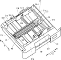
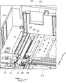
- FIG. 1 is a perspective view showing a paper feed cassette according to one embodiment of the present invention
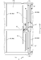
- FIG. 4 is a plan view showing the downstream end of the bottom plate of the paper feed cassette according to one embodiment of the present invention
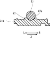
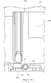
- FIG. FIG. 4 is a cross-sectional view of the receiving portion of the paper feed cassette according to the embodiment of the present invention, viewed from the width direction
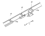
- FIG. 4 is a perspective view showing a receiving portion arranged in the center in the width direction of the paper feed cassette according to the embodiment of the present invention
- FIG. 3 is a plan view showing the downstream end of the paper feed cassette according to one embodiment of the present invention
- FIG. 4 is a perspective view showing a side cursor and a shaft in the paper feed cassette according to one embodiment of the present invention
- FIG. 10 is a diagram of the side cursor and the shaft viewed from the width direction in the paper feed cassette according to the embodiment of the present invention
- FIG. 1 is a cross-sectional view schematically showing the internal structure of the image forming apparatus 1.
- FIG. Fr, Rr, L, and R in each figure indicate the front side, rear side, left side, and right side of the image forming apparatus, respectively.
- An apparatus main body 2 of the image forming apparatus 1 includes a sheet feeding section 3, an electrophotographic image forming section 5, a fixing device 7, and a discharge device 9.
- a discharge tray 11 is formed on the upper surface of the apparatus main body 2 .
- a sheet conveying path 13 is formed in the apparatus main body 2 from the sheet feeding section 3 to the discharging device 9 via the image forming section 5 and the fixing device 7 .
- the sheet feeding unit 3 includes a sheet feeding cassette 21 that accommodates sheets, and a sheet feeding device 23 that feeds sheets along the sheet feeding direction from the sheet feeding cassette 21 toward the conveying path 13 .
- the paper feed cassette 21 is attached to and detached from the apparatus main body 2 along the front-rear direction through an opening (not shown) formed in the front surface of the apparatus main body 2 .
- the upstream side and the downstream side refer to the upstream side and the downstream side in the sheet feeding direction.
- the feeding direction is from left to right.
- a direction intersecting the feeding direction is defined as a width direction.
- the paper feed cassette 21 will be described later.
- the image forming section 5 includes four process cartridges 25 corresponding to toners of four colors (yellow, magenta, cyan, and black), an intermediate transfer belt 27 that circulates, and transfer rollers 29 .
- the four process cartridges 25 are arranged side by side along the running direction of the intermediate transfer belt 27 so as to face the lower track of the intermediate transfer belt 27 .
- the four process cartridges 25 superimpose toner images of respective colors on the running intermediate transfer belt 27 to form them.
- the formed toner image is transferred onto a sheet conveyed along the conveying path 13 at a transfer nip formed between the transfer roller 29 and the intermediate transfer belt 27 .
- the fixing device 7 fixes the toner image transferred to the sheet onto the sheet.
- the discharging device 9 discharges the sheet on which the toner image is fixed.
- the discharged sheets are stacked on the discharge tray 11 .
- FIG. 2 is a perspective view showing the paper feed cassette 21
- FIG. 3 is a plan view showing the downstream end of the bottom plate of the paper feed cassette 21
- FIG. 4A is a sectional view showing the receiving portion
- FIG. Fig. 5 is a plan view showing the lift plate
- Fig. 6 is a perspective view showing the shaft and the side cursor
- Fig. 7 is a view of the shaft and the side cursor viewed from the width direction; .
- the paper feed cassette 21 includes a body portion 31 that stores sheets, a loading plate 33 that is arranged on the bottom plate of the body portion 31, and a lift that is located below the loading plate 33.
- a plate 35 (see FIG. 4) and a pair of side cursors 37 (37F, 37R) supported by the body portion 31 are provided.
- the main body 31 has a shallow box shape with an open top, and is composed of a bottom plate 31a, front and rear side plates 31b and 31c facing each other in the front-rear direction, and left and right side plates 31d and 31e facing each other in the left-right direction. .
- the front side plate 31 b is provided with an outer cover 41 that closes the opening of the apparatus main body 2 when the paper feed cassette 21 is attached to the apparatus main body 2 .
- the bottom plate 31a has dimensions that can accommodate a maximum size (for example, A3 size) paper.
- a pair of first rails 43 extending in the width direction Y are formed at a predetermined interval in the feeding direction X at the downstream end (right end) of the bottom plate 31a.
- a second rail 45 extending in the feeding direction X is formed in the central portion in the width direction Y of the bottom plate 31a. The second rail 45 is formed between the upstream end of the bottom plate 31 a and the first rail 43 .
- a rib 47 protrudes along the width direction Y downstream of the first rail 43 on the bottom plate 31a.
- the rib 47 has a rectangular cross-sectional shape that is short in the height direction and long in the feeding direction X.
- a plurality of (five in this example) receiving portions 47 a are formed on the upper end surface (upper edge) of the rib 47 .
- Each receiving portion 57a is formed in an arcuate shape recessed in a U shape when viewed from the width direction Y.
- three receiving portions 47a are arranged at the center portion in the width direction Y at predetermined intervals, and one receiving portion 47a is provided at each end portion in the width direction Y. Individual receiving portions 47a are arranged.
- the bottom plate 31a has a first guide groove 49a and a second guide groove 49b on the upstream side of the first rail 43 and on the downstream side of the receiving portion 47a. It is formed along the width direction Y.
- the platen plate 33 has a dimension that allows a sheet of the maximum size to be placed, and has a center portion 51 along the feeding direction X and a width direction Y from the center portion 51. and a plurality of (four in this example) projecting portions 53 projecting forward and rearward.
- the multiple projecting portions 53 include first to fourth projecting portions 53-1, 53-2, 53-3, and 53-4 in order from the upstream side.
- the upper surface of the mounting plate 33 (the center portion 51 and the upper surfaces of the first to fourth projecting portions 53-1, 53-2, 53-3, and 53-4) is a sheet mounting surface on which sheets are mounted. be.
- a notch 55 is formed along the feeding direction X in the central portion 51 . Through this notch 55, the second rail 45 of the bottom plate 31a of the main body 31 is exposed.
- the upstream end portion of the first projecting portion 53-1 is rotatably supported by spindles (not shown) provided on the front and rear side plates 31b and 31c of the main body portion 31.
- the mounting plate 33 is rotatable about the support shaft from a horizontal position along the bottom plate 31a of the main body 31 to an inclined position in which the downstream end of the mounting plate 33 rises.
- the lift plate 35 has a rectangular shape with approximately the same width as the central portion 51 of the mounting plate 33. As shown in FIG. The lift plate 35 is fixed to the central portion of the shaft 61 and rotates together with the shaft 61 .
- the shaft 61 is a round shaft and is supported by a receiving portion 47a (see FIGS. 3, 4A, and 4B) formed on the bottom plate 31a of the main body portion 31. As shown in FIG. The receiving portion 47 a is fitted onto the shaft 61 .
- Both ends of the shaft 61 pass through bearing portions 63 provided on the front and rear side plates 31b and 31c of the body portion 31, as shown in FIG.
- a rear end portion 61r of the shaft 61 penetrates the rear side wall 31c and is connected to a drive motor (both not shown) via a coupling and a gear train.
- a front end portion of the shaft 61 is rotatably supported by the front side plate 31b.
- the lift plate 35 rotates downstream with respect to the shaft 61 and is arranged between the downstream end of the central portion 51 of the mounting plate 33 and the bottom plate 31a.
- the pair of side cursors 37 includes a front cursor 37F and a rear cursor 37R.
- the front cursor 37F includes a vertical contact wall 71F along the feeding direction X, a rack plate 73F extending rearward along the width direction Y from the lower end of the contact wall 71F, have.
- a rack gear 75F is formed on the upstream side edge of the rack plate 73F.
- the rear cursor 37R has a vertical contact wall 71R along the feeding direction X and a rack plate 73R extending forward along the width direction Y from the lower end of the contact wall 71R.
- a rack gear 75R is formed on the downstream side edge of the rack plate 73R.
- the front rack plate 73F is made of resin, and the rear contact wall 71R and the rear rack plate 73R are made of metal (for example, sheet metal).
- the paper feed cassette 21 is attached to and detached from the apparatus main body 2 along the front-rear direction.
- a load is applied to the rear contact wall 71R and the rack plate 73R by the accommodated sheets. is made of metal to increase its strength.
- the rack plate 73F on the front side does not receive a load from the stored sheets and does not require high strength, so it is made of resin.
- the contact wall 71F on the front side may also be made of resin.
- substantially rectangular notch portions 77F and 77R are formed by notching the lower edges of the contact walls 71F and 71R on the upstream side.
- the contact walls 71F and 71R are provided with recesses 79 cut out from the lower edges downstream of the cutouts 77F and 77R (see FIGS. 5 and 6). shows only the recess 79F on the front side).
- L-shaped engaging portions (not shown) viewed from the width direction Y are formed at the upstream and downstream ends of the lower edges of the contact walls 71F and 71R.
- the front and rear side cursors 37F and 37R are arranged on the bottom plate 31a of the main body 31 so that the contact walls 71F and 71R face each other in the width direction Y.
- the third projecting portion 53-3 of the mounting plate 33 enters into the notches 77F and 77R of the contact walls 71F and 71R.
- the recesses 79 of the contact walls 71F and 71R are fitted onto the shaft 61 of the lift plate 35.
- the engaging portions of the contact walls 71F and 71R engage with the first and second guide grooves 49a and 49b of the bottom plate 31a.
- the rack plates 73F and 73R are engaged with the first rail 43 formed on the bottom plate 31a, and the rack gears 75F and 75R of the rack plates 73F and 73R are pinion gears 81 (FIGS. 5 and 5) supported by the bottom plate 31a. (See Fig. 6).
- the rack plate 73F moves along the first rail 43 together with the contact wall 71F to move the pinion.
- Gear 81 rotates.
- the rack plate 73R of the rear side cursor 37R moves in the other direction along the first rail 43, and the contact wall 71R moves in the other direction along the first and second guide grooves 49a and 49b. Since the rack plates 73F and 73R are provided with bearings (not shown), the rack plates 73F and 73R move smoothly. As a result, the contact walls 71F and 71R move synchronously toward or away from each other.
- the rack plates 73F, 73R and the pinion gear 81 are an example of an interlocking mechanism that interlocks and moves the pair of side cursors 37F, 37R in the width direction Y. As shown in FIG.
- the contact walls 71F and 71R are positioned between the second and third projecting portions 53-2 and 53-3 of the mounting plate 33 and between the third and fourth projecting portions. Pass between 53-3 and 53-4.
- the contact walls 71F and 71R move toward each other, and the opposing vertical surfaces of the contact walls 71F and 71R come into contact with the side edges of the sheet placed on the platen plate 33, thereby moving the sheet. It is positioned with respect to the center in the width direction Y. In this manner, the inner side surfaces of the contact walls 71F and 71R regulate the position of the seat.
- the paper feed cassette 21 is provided with an end cursor 95 on the bottom plate 31a of the main body 31, as shown in FIG.
- the end cursor 95 engages with the second rail 45 of the bottom plate 31 a and moves in the feeding direction X along the second rail 45 .
- the end cursor 95 abuts on the edge of the sheet placed on the placing plate 33 to position the sheet in the feeding direction X. As shown in FIG.
- the paper feed cassette 21 is pulled out from the apparatus main body 2 , the sheet bundle is placed on the placing plate 33 , and the downstream edge of the sheet bundle is brought into contact with the right side plate 31 e of the main body 31 .
- one of the pair of side cursors 37F and 37R is moved to abut on the side edge of the sheet bundle.
- the other side cursor moves synchronously, and the regulating surfaces of the contact walls 71F and 71R come into contact with the side surfaces of the sheet bundle, thereby positioning the sheet bundle in the width direction Y.
- the end cursor 95 is moved along the second rail 45 and brought into contact with the upstream edge of the sheet bundle. As a result, the sheet bundle is positioned in the feeding direction X. As shown in FIG.
- the paper feed cassette 21 is attached to the apparatus main body 2 .
- the coupling connected to the rear end portion 61r of the shaft 61 of the lift plate 35 is connected to the motor of the device main body 2.
- the shaft 61 rotates and the lift plate 35 rotates upstream.
- the downstream end of the mounting plate 33 is lifted by the lift plate 35, and the mounting plate 33 rotates from the horizontal posture to the inclined posture.
- the downstream end portion of the sheet bundle placed on the platen plate 33 rises.
- the motor is stopped.
- the third projecting portion 53-3 of the mounting plate 33 passes through the notches 77F, 77R of the contact walls 71F, 71R of the pair of side cursors 37F, 37R. Also, the fourth projecting portion 53-4 passes downstream of the pair of side cursors 37F and 37R.
- both ends of the shaft 61 of the lift plate 35 are supported by the front and rear side plates 31b and 31c of the main body 31.
- a load applied to the lift plate 35 from 33 is applied to the front and rear side plates 31b and 31c.
- the shaft 61 is supported by the receiving portions 47a projecting from the bottom plate 31a of the main body portion 31, the load is also applied to these receiving portions 47a, that is, the bottom plate 31a. Since the receiving portions 47a are arranged at the central portion and both end portions in the width direction Y, the load is distributed in the width direction Y and uneven deformation of the main body portion 31 (bottom plate) can be prevented.
- the bottom plate may be deformed into a convex downward shape when viewed from the feeding direction X.
- the shaft 61 is supported at the center and both ends in the width direction Y as in the present embodiment, the load applied to the lift plate 35 is dispersed in the width direction Y, so deformation of the bottom plate 31a is prevented. can be prevented.
- the shaft 61 may be supported only by the receiving portions 47a arranged at the central portion and both ends of the bottom plate 31a. It may be supported by the bearing portion 63 that is mounted.
- the receiving portion 47a has a U-shaped recessed arc shape when viewed from the width direction Y, and is fitted onto the shaft 61, so that the rotation of the shaft 61 can be smoothly guided.
- both ends of the shaft 61 are supported by the front and rear side plates 31b and 31c of the main body 31 outside the side cursors 37F and 37R that have moved to the farthest positions in the width direction Y.
- the rack plates 73F and 73R are guided along the first rails 43 formed on the bottom plate 31a, and the contact walls 71F and 71R move along the shaft 61. guided along.
- the contact walls 71F, 71R and the rack plates 73F, 73R can be stably moved in the width direction Y while maintaining the positional relationship between the contact walls 71F, 71R, and the pair of side cursors 37F, 37R can be moved smoothly. can be implemented.
Landscapes
- Engineering & Computer Science (AREA)
- Mechanical Engineering (AREA)
- Sheets, Magazines, And Separation Thereof (AREA)
Abstract
Description
Claims (8)
- 所定の給送方向に沿って給送されるシートを収容する本体部と、
前記本体部の底板上に配置され、シートが載置されるシート載置面を有する載置板と、
前記給送方向と交差する幅方向に沿って延びるシャフトと、
前記底板と前記載置板との間に配置されて、前記シャフトを中心として回動して前記載置板の前記給送方向の下流側の端部を昇降させるリフト板と、
前記底板上において前記幅方向に沿って互いに接近する方向及び離間する方向に移動可能に支持されて、前記シート載置面に載置されたシートを前記幅方向に位置決めする一対のサイドカーソルと、
前記幅方向に沿って前記底板に形成され、前記一対のサイドカーソルの移動を案内するガイド溝と、を備え、
前記シャフトの両端部は、前記幅方向に最も離間した位置に配置された前記一対のサイドカーソルよりも前記幅方向の外側で、前記本体部に設けられた軸受部に回転可能に支持され、
前記一対のサイドカーソルは、前記シートの側面に当接する当接壁と、前記当接壁の下端に形成され、上方から前記シャフトに外嵌する凹部と、を有し、前記一対のサイドカーソルが前記幅方向に移動する際、前記凹部が前記シャフト上を摺動することを特徴とする給紙カセット。 - 前記底板は、前記給送方向に沿ったリブの上端縁に形成され、前記シャフトを下方から支持する複数の受け部を有し、
前記受け部は、前記幅方向の中央部と両端部とに配置されていることを特徴とする請求項1に記載の給紙カセット。 - 前記シャフトは所定の径を有する丸軸であり、
前記受け部は、前記幅方向から見て、円弧形状に凹んだ形状を有し、前記シャフトに外嵌することを特徴とする請求項2に記載の給紙カセット。 - 前記本体部は、前記底板の前記幅方向の両端部に沿って設けられ、前記幅方向に互いに対向する一対の側板を有し、
前記軸受部は、前記一対の側板に設けられていることを特徴とする請求項1に記載の給紙カセット。 - 前記ガイド溝は、前記シャフトの前記給送方向の上流側及び下流側に配置された第1ガイド溝及び第2ガイド溝を有することを特徴とする請求項1に記載の給紙カセット。
- 前記リフト板は、前記給送方向における上流側の端部が前記シャフトに軸支され前記シャフトを中心として回動することで、前記搬送方向における下流側の端部が前記載置板に当接し、前記載置板の前記下流側の端部を上昇させることを特徴とする請求項1に記載の給紙カセット。
- 前記一対のサイドカーソルを前記幅方向に連動して移動させる連動機構を更に備え、
前記連動機構は、
前記底板に回転可能に支持されたピニオンギアと、
前記一対のサイドカーソルのそれぞれの前記当接壁の下端から前記幅方向の中央に向かって延び、前記ピニオンギアと噛み合うラックギアが形成されたラック板と、を有し、
前記シャフトは、前記ラック板よりも前記給送方向の下流側に配置されていることを特徴とする請求項1に記載の給紙カセット。 - 請求項1に記載の給紙カセットと、
前記給紙カセットから給送されたシートに画像を形成する画像形成部と、を備えることを特徴とする画像形成装置。
Priority Applications (3)
| Application Number | Priority Date | Filing Date | Title |
|---|---|---|---|
| US18/550,335 US12371286B2 (en) | 2021-03-19 | 2022-01-28 | Sheet feeding cassette and image forming apparatus |
| JP2023506829A JP7505637B2 (ja) | 2021-03-19 | 2022-01-28 | 給紙カセット及び画像形成装置 |
| CN202280021308.7A CN117043086A (zh) | 2021-03-19 | 2022-01-28 | 供纸盒以及图像形成装置 |
Applications Claiming Priority (2)
| Application Number | Priority Date | Filing Date | Title |
|---|---|---|---|
| JP2021045862 | 2021-03-19 | ||
| JP2021-045862 | 2021-03-19 |
Publications (1)
| Publication Number | Publication Date |
|---|---|
| WO2022196129A1 true WO2022196129A1 (ja) | 2022-09-22 |
Family
ID=83320314
Family Applications (1)
| Application Number | Title | Priority Date | Filing Date |
|---|---|---|---|
| PCT/JP2022/003371 Ceased WO2022196129A1 (ja) | 2021-03-19 | 2022-01-28 | 給紙カセット及び画像形成装置 |
Country Status (4)
| Country | Link |
|---|---|
| US (1) | US12371286B2 (ja) |
| JP (1) | JP7505637B2 (ja) |
| CN (1) | CN117043086A (ja) |
| WO (1) | WO2022196129A1 (ja) |
Citations (7)
| Publication number | Priority date | Publication date | Assignee | Title |
|---|---|---|---|---|
| JPS58123840U (ja) * | 1982-02-17 | 1983-08-23 | ユ−ザツク電子工業株式会社 | 印刷装置の給紙カセツト |
| JPS59100736U (ja) * | 1982-12-24 | 1984-07-07 | シャープ株式会社 | 給紙カセツト |
| JPH03195635A (ja) * | 1989-12-25 | 1991-08-27 | Daiwa Seiko Inc | 自動給紙装置 |
| JP2005035715A (ja) * | 2003-07-18 | 2005-02-10 | Konica Minolta Business Technologies Inc | 給紙装置と給紙装置を搭載した画像形成装置 |
| JP2008239302A (ja) * | 2007-03-27 | 2008-10-09 | Canon Inc | シート給送装置と画像形成装置 |
| JP2016160088A (ja) * | 2015-03-05 | 2016-09-05 | キヤノン株式会社 | シート積載装置及び画像形成装置 |
| JP2019018937A (ja) * | 2017-07-12 | 2019-02-07 | 京セラドキュメントソリューションズ株式会社 | シート収納装置及びそれを備えた画像形成装置 |
Family Cites Families (9)
| Publication number | Priority date | Publication date | Assignee | Title |
|---|---|---|---|---|
| JP2003201024A (ja) * | 2002-01-07 | 2003-07-15 | Konica Corp | 画像形成装置 |
| JP2013112426A (ja) * | 2011-11-25 | 2013-06-10 | Kyocera Document Solutions Inc | シート給送装置及びそれを備えた画像形成装置 |
| CN204802689U (zh) * | 2015-02-06 | 2015-11-25 | 株式会社理光 | 图像形成装置 |
| JP6347222B2 (ja) * | 2015-03-26 | 2018-06-27 | 京セラドキュメントソリューションズ株式会社 | 画像形成装置 |
| JP6555634B2 (ja) * | 2015-04-03 | 2019-08-07 | 富士ゼロックス株式会社 | 画像形成装置及び供給装置 |
| JP6593309B2 (ja) * | 2016-11-22 | 2019-10-23 | 京セラドキュメントソリューションズ株式会社 | シート収納カセットおよびそれを備えた画像形成装置 |
| JP6929075B2 (ja) * | 2017-02-03 | 2021-09-01 | キヤノン株式会社 | シート支持装置及び画像形成装置 |
| JP6760219B2 (ja) * | 2017-06-29 | 2020-09-23 | 京セラドキュメントソリューションズ株式会社 | シート給送装置およびそれを備えた画像形成装置 |
| CN207986412U (zh) * | 2017-12-31 | 2018-10-19 | 姚涛 | 一种电缆电线卷线盘 |
-
2022
- 2022-01-28 CN CN202280021308.7A patent/CN117043086A/zh active Pending
- 2022-01-28 JP JP2023506829A patent/JP7505637B2/ja active Active
- 2022-01-28 WO PCT/JP2022/003371 patent/WO2022196129A1/ja not_active Ceased
- 2022-01-28 US US18/550,335 patent/US12371286B2/en active Active
Patent Citations (7)
| Publication number | Priority date | Publication date | Assignee | Title |
|---|---|---|---|---|
| JPS58123840U (ja) * | 1982-02-17 | 1983-08-23 | ユ−ザツク電子工業株式会社 | 印刷装置の給紙カセツト |
| JPS59100736U (ja) * | 1982-12-24 | 1984-07-07 | シャープ株式会社 | 給紙カセツト |
| JPH03195635A (ja) * | 1989-12-25 | 1991-08-27 | Daiwa Seiko Inc | 自動給紙装置 |
| JP2005035715A (ja) * | 2003-07-18 | 2005-02-10 | Konica Minolta Business Technologies Inc | 給紙装置と給紙装置を搭載した画像形成装置 |
| JP2008239302A (ja) * | 2007-03-27 | 2008-10-09 | Canon Inc | シート給送装置と画像形成装置 |
| JP2016160088A (ja) * | 2015-03-05 | 2016-09-05 | キヤノン株式会社 | シート積載装置及び画像形成装置 |
| JP2019018937A (ja) * | 2017-07-12 | 2019-02-07 | 京セラドキュメントソリューションズ株式会社 | シート収納装置及びそれを備えた画像形成装置 |
Also Published As
| Publication number | Publication date |
|---|---|
| US12371286B2 (en) | 2025-07-29 |
| US20240150143A1 (en) | 2024-05-09 |
| CN117043086A (zh) | 2023-11-10 |
| JP7505637B2 (ja) | 2024-06-25 |
| JPWO2022196129A1 (ja) | 2022-09-22 |
Similar Documents
| Publication | Publication Date | Title |
|---|---|---|
| US9714146B2 (en) | Sheet storage apparatus and image forming apparatus | |
| JPH0569950A (ja) | 給紙カセツト | |
| US8496243B2 (en) | Sheet width regulating device and image forming apparatus with sheet width regulating device | |
| US8469355B2 (en) | Sheet feeder and image forming apparatus | |
| EP2769947B1 (en) | Sheet feed apparatus, and image forming apparatus and image reading apparatus including the same | |
| JP5769747B2 (ja) | シート給送装置及び画像形成装置 | |
| JP2015020877A (ja) | シート給送装置及び画像形成装置 | |
| US7954807B2 (en) | Sheet-feeding device and image forming apparatus provided with the same | |
| JP7505637B2 (ja) | 給紙カセット及び画像形成装置 | |
| JP7127397B2 (ja) | 画像形成装置 | |
| JP6046101B2 (ja) | 給紙カセットおよびこれを備える画像形成装置 | |
| JP7262989B2 (ja) | シート給送装置及び画像形成装置 | |
| JP2019194120A (ja) | シート給送装置及び画像形成装置 | |
| JP6406271B2 (ja) | シート給送装置およびそれを備えた画像形成装置 | |
| US12485684B2 (en) | Image recording apparatus | |
| JP2011042455A (ja) | 給紙装置及び画像形成装置 | |
| JP2024018745A (ja) | 給紙装置および画像形成装置 | |
| JP6424857B2 (ja) | シート給送装置およびそれを備えた画像形成装置 | |
| JP2023128206A (ja) | シート搬送装置およびそれを備えた画像形成装置 | |
| JP2007112558A (ja) | 給紙装置および画像形成装置 | |
| JP2019131347A (ja) | 給紙カセット及び画像形成装置 | |
| JP4557258B2 (ja) | 給紙トレイ、画像形成装置、用紙給紙手段を備える装置 | |
| JP2007182320A (ja) | シート材給送装置および画像形成装置 | |
| JP2015020878A (ja) | シート給送装置及び画像形成装置 | |
| JP2005178999A (ja) | 給紙装置および画像形成装置 |
Legal Events
| Date | Code | Title | Description |
|---|---|---|---|
| 121 | Ep: the epo has been informed by wipo that ep was designated in this application |
Ref document number: 22770891 Country of ref document: EP Kind code of ref document: A1 |
|
| WWE | Wipo information: entry into national phase |
Ref document number: 2023506829 Country of ref document: JP |
|
| WWE | Wipo information: entry into national phase |
Ref document number: 18550335 Country of ref document: US Ref document number: 202280021308.7 Country of ref document: CN |
|
| NENP | Non-entry into the national phase |
Ref country code: DE |
|
| 122 | Ep: pct application non-entry in european phase |
Ref document number: 22770891 Country of ref document: EP Kind code of ref document: A1 |
|
| WWG | Wipo information: grant in national office |
Ref document number: 18550335 Country of ref document: US |