WO2022196002A1 - 負荷監視装置及び負荷監視方法 - Google Patents
負荷監視装置及び負荷監視方法 Download PDFInfo
- Publication number
- WO2022196002A1 WO2022196002A1 PCT/JP2021/047105 JP2021047105W WO2022196002A1 WO 2022196002 A1 WO2022196002 A1 WO 2022196002A1 JP 2021047105 W JP2021047105 W JP 2021047105W WO 2022196002 A1 WO2022196002 A1 WO 2022196002A1
- Authority
- WO
- WIPO (PCT)
- Prior art keywords
- motor
- driver
- temperature
- current value
- load
- Prior art date
- Legal status (The legal status is an assumption and is not a legal conclusion. Google has not performed a legal analysis and makes no representation as to the accuracy of the status listed.)
- Ceased
Links
Images

Classifications
-
- H—ELECTRICITY
- H02—GENERATION; CONVERSION OR DISTRIBUTION OF ELECTRIC POWER
- H02P—CONTROL OR REGULATION OF ELECTRIC MOTORS, ELECTRIC GENERATORS OR DYNAMO-ELECTRIC CONVERTERS; CONTROLLING TRANSFORMERS, REACTORS OR CHOKE COILS
- H02P29/00—Arrangements for regulating or controlling electric motors, appropriate for both AC and DC motors
- H02P29/02—Providing protection against overload without automatic interruption of supply
-
- H—ELECTRICITY
- H02—GENERATION; CONVERSION OR DISTRIBUTION OF ELECTRIC POWER
- H02P—CONTROL OR REGULATION OF ELECTRIC MOTORS, ELECTRIC GENERATORS OR DYNAMO-ELECTRIC CONVERTERS; CONTROLLING TRANSFORMERS, REACTORS OR CHOKE COILS
- H02P29/00—Arrangements for regulating or controlling electric motors, appropriate for both AC and DC motors
- H02P29/60—Controlling or determining the temperature of the motor or of the drive
Definitions
- the present disclosure relates to a load monitoring device and load monitoring method for monitoring the load of a motor and a driver that controls the operation of the motor.
- Patent Literature 1 describes a method for controlling a motor by referring to a control table using control instruction information and the operating environment temperature of the motor detected by a temperature sensor, reading the corresponding control amount (motor torque). It is Further, in Patent Document 2, the amount of temperature rise in the motor is obtained based on the amount of current flowing through the motor and the amount of heat released from the motor, and the control parameters of the motor (such as the torque constant and resistance value of the motor) are calculated based on the amount of temperature rise. ) is described.
- JP-A-7-163182 Japanese Patent Application Laid-Open No. 2004-318709
- the present invention has been made in view of such problems, and its object is to provide a load monitoring device and a load monitoring method that can bring out the original performance of the motor and driver as much as possible.
- a load monitoring device that monitors the load on the motor and the driver that controls the operation of the motor employs the following configuration. That is, the load monitoring device measures the temperature of the motor at a first temperature using a current value obtaining unit that obtains the value of current supplied to the motor, and a first thermal model that indicates the relationship between the current value and the amount of heat generated by the motor.
- a second temperature estimating unit that estimates the temperature of the driver as a second temperature by a second thermal model that indicates the relationship between the current value and the amount of heat generated by the driver; and a first threshold value for the motor to determine whether the motor is in an overloaded state, and has a first load characteristic that indicates a time that can be applied for a predetermined current value with respect to the motor.
- a first control structure configured to compare a second temperature to a second threshold for a driver to determine whether the driver is overloaded, and for a predetermined current value for an applicable time for the driver; and a second control structure having a second load characteristic indicating and when the load determination unit determines that at least one of the motor and the driver is in an overloaded state, abnormal information about the overloaded state
- a first load characteristic and a second control in a first control structure based on an output unit to output, a first ambient temperature that is the ambient temperature of the motor, and a second ambient temperature that is the ambient temperature of the driver a corrector for correcting the second load characteristic of the structure.
- the present invention also includes a load monitoring method, a load monitoring program, and a recording medium recording such a program, which have the same characteristics as the load monitoring device described above.
- each of the first load characteristic and the second load characteristic is corrected based on the ambient temperature of the motor and the ambient temperature of the driver.
- it is determined whether or not a current larger than the rated current has been applied to the motor and driver for a period exceeding the applicable time, based on the threshold value corresponding to the corrected load characteristics.
- the correcting unit corrects the first load characteristic so that the application possible time in the first load characteristic increases as the first ambient temperature decreases while maintaining the rated current of the motor, and the driver
- the second load characteristic may be corrected such that the application possible time in the second load characteristic becomes longer as the second ambient temperature becomes lower while maintaining the rated current of .
- the correction unit corrects the first load characteristic so that the rated current of the motor increases and the application possible time in the first load characteristic increases as the first ambient temperature decreases
- the second load characteristic may be corrected such that the lower the second ambient temperature, the more the rated current of the driver is increased and the longer the application possible time in the second load characteristic.
- the load determination unit determines the first current value as the allowable current value of the motor and the driver from the first load characteristic and the second load characteristic corrected by the correction unit, and the first current value A first applicable time corresponding to the value is calculated, and from the first applicable time and information on the configuration of the power cable connecting the motor and the driver, the second value as the allowable current value of the power cable is calculated. and comparing the second current value with the first current value to provide information indicating an overload condition of the power cable when the second current value is less than or equal to the first current value may be output.
- the load determination unit determines the allowable current value of the power cable ( Information indicating whether the second current value) is equal to or less than the allowable current value (first current value) of the motor and driver, and indicates an overload condition when the second current value is equal to or less than the first current value to output
- the allowable current value of the power cable Information indicating whether the second current value
- first current value the allowable current value of the motor and driver
- the above load monitoring device may further include a reception unit that receives input of information regarding the configuration of the power cable.
- the original performance of the motor and driver can be brought out as much as possible.
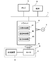
- FIG. 1 is a diagram showing a schematic configuration of a motor control system.
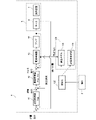
- FIG. 2 is a diagram showing a schematic configuration of a control system including a motor.
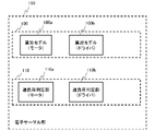
- FIG. 3 is a diagram showing a control structure formed by the driver of the embodiment.
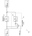
- FIG. 4 is a diagram showing a configuration example of a calculation model for a motor.
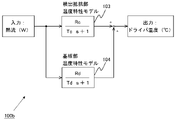
- FIG. 5 is a diagram showing a configuration example of a calculation model for a driver.
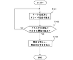
- FIG. 6 is a flow chart showing a first processing example of the electronic thermal unit.
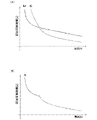
- FIG. 7A is an explanatory diagram of overload characteristic graphs of the motor and the driver, and
- FIG. 7B is an explanatory diagram of the overload characteristic graph of the entire system.
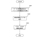
- FIG. 8 is a flowchart illustrating an example of processing by a setting unit; FIG.
- FIG. 9 is an overload characteristic graph of the entire system when corrected by the first correction method.
- FIG. 10 is a graph of overload characteristics of the entire system corrected by the second correction method.
- FIG. 11 is a flow chart showing a second processing example of the electronic thermal unit.
- FIG. 12 is a flowchart showing a third processing example of the electronic thermal unit.
- the load monitoring device according to the embodiment of the present application will be described below based on the drawings.
- the configuration of the embodiment is an example, and is not limited to the configuration of the embodiment.
- FIG. 1 is a schematic configuration diagram of a control system including a driver 4 that also operates as a load monitoring device of this embodiment.
- the control system includes a network 1, a motor 2, a load device 3, a driver 4, a PLC (Programmable Logic Controller) 5, a power cable 8, and a terminal 9.
- PLC Programmable Logic Controller
- the control system is a system for driving and controlling the load device 3 together with the motor 2 .
- the motor 2 and the load device 3 are the controlled objects 6 controlled by the control system.
- the load device 3 various mechanical devices (for example, an arm of an industrial robot and a transfer device) can be exemplified.
- the motor 2 is incorporated in the load device 3 as an actuator for driving the load device 3 .
- the motor 2 is an AC servomotor having a stator with windings and a rotor.
- the motor 2 may have a structure in which windings are wound around its stator and has a rotor, and its specific structure is not limited to an AC servomotor.
- This feedback-transmitted parameter signal includes, for example, position information about the rotational position (angle) of the rotating shaft of the motor 2, information about the rotating speed of the rotating shaft, and the like.
- the driver 4 receives an operation command signal regarding the operation (motion) of the motor 2 from the PLC 5 via the network 1 and also receives a feedback signal output from an encoder connected to the motor 2 .
- the driver 4 performs servo control for driving the motor 2 based on the operation command signal from the PLC 5 and the feedback signal from the encoder. is supplied to the motor 2 through the power cable 8 so as to follow .
- the AC power sent from the AC power supply 7 to the driver 4 is used as the driving current supplied to the motor 2 .
- the driver 4 is of a type that receives three-phase alternating current, but may be of a type that receives single-phase alternating current.
- the servo control by the driver 4 is feedback control using the position controller 41, the speed controller 42, and the current controller 43 that the driver 4 has.
- the driver 4 has a position controller 41, a speed controller 42, and a current controller 43, and the servo control is executed by these processes.
- Driver 4 also includes an electronic thermal section 150 (see FIG. 2) to protect motor 2 and driver 4 from overheating damage.
- the electronic thermal unit 150 estimates the winding temperature of the motor 2 and the temperature of the driver 4, and determines the overheating state of the motor 2 based on the estimated temperatures.
- the control structure is formed by executing a predetermined control program in the driver 4 having a predetermined arithmetic unit, memory, and the like.
- the position controller 41 performs proportional control (P control), for example. Specifically, the speed command is calculated by multiplying the positional deviation, which is the difference between the positional command notified from the PLC 5 and the detected position, by the position proportional gain Kpp.
- the position controller 41 has a position proportional gain Kpp as a control parameter in advance.
- the speed controller 42 performs proportional integral control (PI control), for example. Specifically, the integral of the speed deviation, which is the deviation between the speed command and the detected speed calculated by the position controller 41, is multiplied by the speed integral gain Kvi, and the sum of the calculated result and the speed deviation is the speed proportional gain Kvp.
- a torque command is calculated by multiplying by .
- the speed controller 42 has a speed integral gain Kvi and a speed proportional gain Kvp as control parameters in advance. Also, the speed controller 42 may perform P control instead of PI control. In this case, the speed controller 42 has a speed proportional gain Kvp as a control parameter in advance.
- current controller 43 generates a command voltage for driving amplifier 44 based on the torque command calculated by speed controller 42 .
- the amplifier 44 outputs a drive current for driving the motor 2 according to the generated command voltage, and the motor 2 is driven and controlled accordingly.
- the current controller 43 includes a filter (first-order low-pass filter) and one or a plurality of notch filters related to the torque command, and has cutoff frequencies related to the performance of these filters as control parameters.
- the current controller 43 also includes a current detector that detects the current command supplied from the amplifier 44 to the motor 2, and the current command detected by the current detector is fed back to the subtractor.
- the control structure of the driver 4 includes a speed feedback system with the speed controller 42, the current controller 43, and the controlled object 6 as forward elements. Includes a feedback system.
- the control structure configured in this manner allows the driver 4 to servo-control the motor 2 so as to follow the position command supplied from the PLC 5 .
- the motor 2 When the motor 2 is servo-controlled in this way, if an excessive load (for example, a load exceeding the rated load of the motor 2) is applied to the motor 2 for a relatively long time, the windings of the motor 2 may Excessive current will flow for a long time. This may cause the winding temperature to rise excessively, resulting in its burning. In addition, there is a risk that the temperature of the driver 4 or the power cable 8 will rise excessively due to the supply of a current higher than the rated current from the driver 4 to the motor 2 for a long period of time, resulting in burnout. In order to protect the motor 2 , the driver 4 and the power cable 8 from such damage as burnout, the driver 4 has an electronic thermal section 150 .
- an excessive load for example, a load exceeding the rated load of the motor 2
- the windings of the motor 2 may Excessive current will flow for a long time. This may cause the winding temperature to rise excessively, resulting in its burning.
- the electronic thermal unit 150 has a calculation model 100 and an overload determination unit 110 .
- the calculation model 100 includes a calculation model 100 a for the motor 2 and a calculation model 100 b for the driver 4 .
- the overload determination unit 110 includes an overload determination unit 110a for the motor 2 corresponding to the calculation model 100a, and an overload determination unit 110b for the driver 4 corresponding to the calculation model 100b.
- FIG. 4 shows a schematic structure of the calculation model 100a of the motor 2.
- the calculation model 100a is a program for calculating the winding temperature of the motor 2 in the electronic thermal unit 150, and outputs the winding temperature of the motor 2 when the heat flow in the motor 2 is given as its input.
- the heat flow can be regarded as a so-called copper loss caused by the electrical resistance of the winding coils of the motor 2, and is proportional to the square of the current flowing through the winding coils.
- the calculation model 100a is a thermal model showing the relationship between the current value supplied to the motor 2 and the amount of heat generated by the motor 2.
- the calculation model 100 supplies the heat flow to the motor 2 according to the command voltage of the power control unit 43. It is calculated by obtaining the current value by detecting the current (current command) to be applied, and obtaining the amount of heat per unit time from this current value.
- the calculation model 100 operates as a current value acquisition unit that acquires the current value supplied to the motor 2 .
- the calculation model 100a includes a winding temperature characteristic model 101 and a stator temperature characteristic model 102 as sub-models constituting the calculation model 100a itself.
- the winding temperature characteristic model 101 is a model for calculating the temperature characteristic of the winding when the thermal influence of the stator is virtually eliminated in the motor 2 .
- the stator temperature characteristic model 102 includes a reference model 102' and an iron loss coefficient Kr whose argument is the rotation speed (rpm) of the rotor of the motor 2.
- the reference model 102 ′ is a model for calculating the temperature characteristics of the stator when the thermal effects of the windings are virtually eliminated in the motor 2 .
- the iron loss coefficient Kr can vary in value depending on the rotation speed of the rotor.
- stator temperature characteristic model 102 In the stator temperature characteristic model 102, the input heat flow multiplied by (1+Kr) is input to the reference model 102', and the output of the stator temperature characteristic model 102 is calculated. Since the calculation model 100a has such a stator temperature characteristic model 102, it is possible to reflect the iron loss caused by the rotation of the rotor in the temperature characteristic of the stator. Estimation of line temperature can be realized more suitably.
- the calculation model 100a includes the winding temperature characteristic model 101 and the stator temperature characteristic model 102, and the sum of the outputs of each model is calculated as the winding temperature of the motor 2, as shown in FIG.
- the winding temperature of the motor is calculated with consideration given to the correlation between the stator and the windings.
- the winding temperature characteristic model 101 is represented by Equation 1 below, including the thermal resistance Ra and the thermal time constant Ta of the winding, which are parameters related to the temperature characteristic of the winding (winding-related parameters).
- the thermal resistance Ra is a value that indicates the difficulty of heat transfer, and is a parameter that indicates the amount of temperature rise per amount of heat generated per unit time.
- the thermal resistance when the windings of the motor 2 are treated as a thermally homogeneous object is adopted.
- the reference model 102' of the stator temperature characteristic model 102 includes the thermal resistance Rb and the thermal time constant Tb of the stator, which are parameters related to the temperature characteristic of the stator (stator-related parameters), and is expressed by Equation 2 below. expressed.
- the definition of the thermal resistance Rb is the same as the definition of the thermal resistance Ra described above, and in this embodiment, the thermal resistance when the stator of the motor is treated as a thermally homogeneous object is adopted.
- the thermal time constant Tb is a parameter representing the degree of responsiveness of the stator to temperature changes, and has the same definition as the thermal time constant Ta described above.
- Stator temperature characteristic model Rb/(Tb ⁇ s+1) (Formula 2)
- the calculation model 100 a the input (heat flow in the motor 2 ) is transferred to the winding temperature characteristic model 101 and the stator temperature characteristic model 102 . Then, the outputs of each model are added to obtain the output of the calculation model, that is, the estimated temperature of the motor windings.
- the calculation model 100a a value obtained by multiplying the outputs of the models 101 and 102 by a predetermined gain may be added.
- FIG. 5 shows a configuration example of the calculation model 100b for the driver.
- the calculation model 100 b is a model for calculating temperature characteristics of a predetermined position of the driver 4 in the electronic thermal unit 150 .
- the predetermined position may be any position where heat is generated in accordance with the supply of current to the motor 2.
- it is a position where a predetermined circuit such as an IGBT or a current detector included in the driver 4 is mounted.
- the calculation model 100b includes a detection resistor temperature characteristic model 103 and a substrate temperature characteristic model 104 as sub-models constituting the calculation model 100b itself.
- the detection resistor part temperature characteristic model 103 is a model for calculating the temperature characteristic of the current detector (current detection resistor) when the thermal influence of the entire substrate of the driver 4 is virtually eliminated.
- the substrate part temperature characteristic model 104 is used for calculating the temperature characteristic of the entire substrate of the driver 4 including the peripheral substrate of the current detection resistor when the thermal influence of the current detection resistor is virtually eliminated in the driver 4. is a model.
- the detection resistor part temperature characteristic model 103 includes the thermal resistance Rc and the thermal time constant Tc related to the current detection resistor, which are parameters related to the temperature characteristics of the detection resistor part (parameters related to the detection resistor part), and is represented by Equation 3 below. be done.
- the definition of the thermal resistance Rc is the same as the definition of the thermal resistance Ra described above, and in this embodiment, the thermal resistance when the current detection resistor is treated as a thermally homogeneous object is adopted.
- the thermal time constant Tc is a parameter representing the degree of responsiveness of the current detection resistor to temperature changes, and has the same definition as the thermal time constant Ta described above.
- Detection resistor part temperature characteristic model Rc/(Tc ⁇ s+1) (Formula 3)
- the substrate temperature characteristic model 104 includes the thermal resistance Rd and the thermal time constant Td of the substrate of the driver 4, which are parameters related to the temperature characteristics of the substrate (substrate related parameters), and is expressed by the following equation 4. .
- the definition of the thermal resistance Rd is the same as the definition of the thermal resistance Ra described above, and in this embodiment, the thermal resistance when the entire substrate of the driver 4 is treated as a thermally uniform object is adopted.
- the thermal time constant Td is a parameter representing the degree of responsiveness of the driver 4 to temperature changes of the substrate, and has the same definition as the thermal time constant Ta described above.
- Substrate temperature characteristic model Rd/(Td ⁇ s+1) (Formula 4)
- the calculation model 100b is a thermal model showing the relationship between the value of the current supplied to the motor 2 and the amount of heat generated by the driver 4, and the heat flow dependent on the current (detected current) detected as the output of the amplifier 44 is It is delivered to the detection resistor part temperature characteristic model 103 and the substrate part temperature characteristic model 104 as an input. Then, the outputs of each model are added to obtain the output of the calculated model, that is, the temperature of the driver 4 (referred to as "driver temperature"). When adding the outputs of the models 103 and 104, a value obtained by multiplying the outputs of the models 103 and 104 by a predetermined gain may be added. By configuring the calculation model 100b in this way, the driver temperature is estimated in consideration of the correlation between the current detection resistor and the substrate.
- the calculation models 100a and 100b each output the temperature of the motor 2 and the driver temperature.
- the overload determination unit 110a of the overload determination unit 110 determines whether the motor 2 is likely to be overloaded based on the temperature of the motor 2 (referred to as "motor temperature"), which is the output of the calculation model 100a. In other words, it is determined whether the temperature of the windings of the motor 2 is likely to rise excessively.
- the overload determination unit 110b of the overload determination unit 110 determines whether there is a possibility that the driver 4 will reach an overloaded state, in other words, whether the driver 4 is globally or locally It is determined whether there is a possibility that the temperature will rise excessively.
- the driver 4 protects the system including the motor 2 and the driver 4. can stop its drive.
- the calculation model 100 corresponds to a calorific value estimation unit
- the overload determination unit 110 corresponds to a load determination unit and an output unit.
- FIG. 6 is a flowchart showing a first processing example of the electronic thermal unit 150.
- the calculation models 100a and 100b of the electronic thermal unit 150 calculate the motor temperature and the driver temperature.
- the calculation model 100a calculates the motor temperature (estimated value) according to the heat flow as the heat load calculation of the motor 2 .
- the calculation model 100b calculates the driver temperature (estimated value) according to the heat flow as the heat load calculation of the driver 4.
- FIG. The order of calculation of each temperature is arbitrary, and may be executed in parallel.
- the overload determination unit 110 determines whether either the motor temperature or the driver temperature exceeds the threshold. That is, the overload determination unit 110a determines whether the motor temperature exceeds the threshold for the motor 2, and the overload determination unit 110b determines whether the driver temperature exceeds the threshold for the driver 4. The order of these determinations is arbitrary, and these determinations may be performed in parallel. Once it is determined that either threshold has been exceeded, the remaining determinations may be aborted or stopped. If it is determined that either the motor temperature or the driver temperature exceeds the threshold, the process proceeds to step S103; otherwise, the process proceeds to step S101.
- the threshold for the motor 2 is, for example, the allowable maximum temperature defined by the insulation class of the motor 2 . For example, when the insulation class of the motor 2 is F class, the allowable maximum temperature is 155°C.
- the threshold for the driver 4 is, for example, the allowable maximum temperature set for protection of the IGBT in the driver 4 .
- step S103 the electronic thermal unit 150 outputs information indicating an overheating state (abnormality or warning) of the motor 2 and driver 4 on the assumption that an abnormal temperature rise of the motor 2 and driver 4 is detected.
- Information is output by light emission or flashing of an LED, output of a warning sound, display of information on a display, and the like.
- the configuration for outputting may be provided in the driver 4 , and the information may be reported (displayed, etc.) using a display or speaker provided in the terminal 9 .
- the electronic thermal unit 150 may have a configuration for automatically stopping the operation of the driver 4 as well as outputting information indicating abnormality/warning. However, the operation of the driver 4 may be stopped manually by the user who received the information.
- the terminal 9 is used by the user to make various settings for the electronic thermal unit 150 through the setting unit 120 provided in the driver 4 . Also, the terminal 9 is used to notify the user of various information by displaying the information indicating the abnormality/warning described above.
- the setting unit 120 may be implemented by a processor (CPU) provided in the driver 4 executing a program, or may be implemented by a dedicated circuit (hardware) implemented in the driver 4 .
- the terminal 9 has a processor, memory, input device, display, communication interface, and the like. By executing a program stored in the memory, the processor reads/writes information from/to the memory, accepts information input by the user using an input device, displays information on the display, and communicates information with the setting unit 120 by controlling the communication interface. Send and receive.
- the user can turn on/off the heat load calculation for the motor 2 and the driver 4 respectively. That is, the user can input information indicating ON or OFF of each of the calculation models 100a and 100b to the terminal 9 from the input device.
- the setting unit 120 turns on/off the corresponding calculation models 100a and 100b based on the information indicating on or off.
- the setting unit 120 turns on/off the corresponding calculation models 100a and 100b based on the information indicating on or off.
- the calculation load of the processor (CPU) can be reduced.
- parameters to be set in the calculation models 100a and 100b of the motor 2 and the driver 4 are set. 1 or 2 or more are stored.
- the user turns on the heat load calculation for each of the motor 2 and the driver 4 on the terminal 9 and inputs the type of each of the motor 2 and the driver 4. are set in the calculation models 100a and 100b, and threshold values corresponding to the respective types of the motor 2 and the driver 4 are set in the overload determination units 110a and 100b.
- the setting unit 120 automatically changes parameters (thermal time constant, etc.) and thresholds for thermal load calculation according to the operation time (energization time) of the motor 2 or the ambient temperature of the motor 2 and the driver 4. can be done.
- the driver 4 measures the operation time (energization time) of the motor 2, and can use the measured value for changing parameters and threshold values.
- the ambient temperature may be predicted from the value of the temperature sensor in the encoder of the motor 2 or the value of the temperature sensor of the radiator in the driver 4, or the value of the temperature sensor that measures the outside air temperature may be used as the ambient temperature. may be used.
- the setting unit 120 when the operating time exceeds a predetermined time, the setting unit 120 makes the value of the thermal time constant smaller than the reference value. Also, when the ambient temperature is higher than the reference temperature or the range of the reference temperature, the setting unit 120 lowers the threshold. Conversely, if the ambient temperature is lower than the reference temperature range, the setting unit 120 raises the threshold. In this way, the motor 2 can be suitably used while protecting the motor 2 and the driver 4 according to the usage conditions of the motor 2 .
- the setting unit 120 operates as a “control unit”, and uses parameters and thresholds for thermal load calculation for the motor 2 and the driver 4 to calculate thermal curves (overload characteristic graphs) for the motor 2 and the driver 4, respectively. can be generated and output. Furthermore, the setting unit 120 can generate and output information obtained by synthesizing the information indicating the overload characteristic graph of the motor 2 and the information indicating the overload characteristic graph of the driver 4 .
- the overload characteristic graph is a graph showing changes in the time until an overheating state is detected (detection time) when a current greater than the rated current is supplied.
- the overload characteristic is usually represented by a graph in which the abscissa indicates the current above the rated value and the ordinate indicates the time until the overload (overheating state) is detected (detection time).
- the time until an overload is detected is the time (applicable time) during which a predetermined current greater than the rated current is allowed to be continuously applied to the motor 2 and the driver 4. I can say.
- the vertical axis represents the application possible time instead of the detection time.
- FIG. 7A shows a graph M showing the overload characteristics of the motor 2 and a graph D showing the overload characteristics of the driver 4.
- FIG. in the overload characteristic graph the larger the current, the shorter the applicable time. Numerical values on which the graphs M and D are based may be generated in the driver 4 or generated in the terminal 9 .
- the terminal 9 processor displays the graphs M and D on the terminal 9 display. Thereby, the user can grasp the overload characteristics of each of the motor 2 and the driver 4 .
- FIG. 7B shows a graph S obtained by synthesizing the graph M showing the overload characteristics of the motor 2 and the graph D showing the overload characteristics of the driver 4 .
- the terminal 9 processor displays the graph S on the terminal 9 display. This allows the user to grasp the overload characteristics of the entire system including the motor 2 and the driver 4 that satisfy the overload characteristics of both the motor 2 and the driver 4 .
- the setting unit 120 uses the value of the temperature sensor in the encoder as the ambient temperature of the motor 2 and the value of the temperature sensor of the radiator of the driver 4 as the ambient temperature of the driver 4 to The overload characteristic graph of can be corrected.
- FIG. 8 is a flowchart showing a processing example of the setting unit 120.
- FIG. In this processing example it is assumed that the overload characteristic graphs M and D of the motor 2 and the driver 4 and the overload characteristic graph S of the entire system as shown in FIG. 7 are generated as an initial state.
- the setting unit 120 acquires the ambient temperature of the motor 2 and the ambient temperature of the driver 4 from the temperature sensor in the encoder and the temperature sensor in the radiator.
- step S202 the setting unit 120 corrects the overload characteristic graphs of the motor 2 and the driver 4 based on the ambient temperature of the motor 2 and the ambient temperature of the driver 4 obtained in step S201. Then, in step S203, the setting unit 120 sets the parameters corresponding to the overload characteristic graphs of the motor 2 and the driver 4 corrected in step S203 to the calculation models 100a and 100b, respectively, and sets the threshold value to the overload determination unit. 110a and 100b respectively.
- the setting unit 120 outputs to the current controller 43 a command for applying the first voltage for generating the overload characteristic graph M.
- FIG. 1 In the first voltage application, a voltage is applied to supply the motor 2 with a current that is 200% of the rated current of the motor 2 .
- the setting unit 120 calculates the ambient temperature of the motor 2 3 seconds, 10 seconds, and 20 seconds after the application of the first voltage (energization).
- the ambient temperature of the motor 2 after energization is calculated by the resistance method using the resistance temperature coefficient of copper represented by Equation 5 below.
- Equation 5 R1 is the winding resistance value of the motor 2 at the start of energization, and R2 is the winding resistance value of the motor 2 after energization. These winding resistance values are calculated from the current values detected by the current detector. Further, t1 is the ambient temperature of the motor 2 at the start of energization, and t2 is the ambient temperature of the motor 2 after energization. Here, the value of the temperature sensor in the encoder is used for t1. ⁇ t is the amount of change in the ambient temperature of the motor 2 at the start of energization and after energization. The value of the temperature sensor in the encoder is used for ⁇ t. When the ambient temperature rises after energization, the value is subtracted by ⁇ t, and when the ambient temperature drops, the value is added by ⁇ t.
- the setting unit 120 determines the ambient temperature t2 of the motor 2 at three points after 3 seconds, 10 seconds, and 20 seconds after the energization, and determines the excess temperature at the first voltage application passing through these three points. Generate a load factor curve. Then, the setting unit 120 determines the thermal time constant Ta for the windings of the motor 2, the thermal time constant Tb for the stator, and the ratio between the thermal time constant Ta and the thermal time constant Tb from the curve of the overload factor. Calculate the thermal resistance ratio time constant.
- the setting unit 120 outputs a command for applying the second voltage to the current controller 43 .
- a voltage is applied to supply the motor 2 with a current of 300% of the rated current of the motor 2 .
- the setting unit 120 calculates the ambient temperature t2 of the motor 2 three seconds after the application of the second voltage (energization).
- the ambient temperature t2 of the motor 2 after energization is calculated by the resistance method represented by Equation 5 described above.
- the setting unit 120 generates a curve of the overload rate when the second voltage is applied from the thermal time constant Ta, the thermal time constant Tb, and the thermal resistance ratio time constant Tr calculated from the result of the first voltage application. do. It should be noted that the setting unit 120 determines that the curve of the generated overload rate when the second voltage is applied is appropriate based on the ambient temperature t2 of the motor 2 three seconds after the application of the second voltage and the threshold value for the motor 2. You can check whether it is
- the setting unit 120 obtains the overload characteristic graph M of the motor 2 by synthesizing the curve of the overload factor when the first voltage is applied and the curve of the overload factor when the second voltage is applied.
- Equation 5 the generation of the overload characteristic graph D of the driver 4 is performed using Equation 5 in the same way as the generation of the overload characteristic graph M of the motor 2.
- R1 is the current detection resistance value of the driver 4 at the start of energization
- R2 is the current detection resistance value of the driver 4 after energization.
- t1 is the ambient temperature of the driver 4 at the start of energization
- t2 is the ambient temperature of the driver 4 after energization.
- the temperature sensor value of the radiator in the driver 4 is used for t1.
- .DELTA.t is the change in the ambient temperature of the driver 4 between the start of energization and after energization.
- the temperature sensor value of the radiator is used.
- the setting unit 120 calculates the thermal time constant Tc related to the detection resistor unit of the driver 4, the thermal time constant Td related to the substrate unit, the thermal time constant Tc and the thermal time constant Tc from the curve of the overload rate when the first voltage is applied.
- a thermal resistance ratio time constant which is a ratio to the constant Td, is calculated. It should be noted that the setting unit 120 generates an overload value during application of the second voltage based on the ambient temperature t2 of the motor 2 three seconds after the application of the second voltage and the threshold value for the driver 4. It may be checked whether the rate curve is correct.
- the setting unit 120 regenerates the overload characteristics graphs of the motor 2 and the driver 4 using the ambient temperature of the motor 2 and the ambient temperature of the driver 4 acquired in step S201.
- the setting unit 120 sets the overload characteristic of the motor 2 so that the application possible time in the overload characteristic graph of the motor 2 increases as the ambient temperature of the motor 2 decreases while the rated current of the motor 2 is maintained. Correct the graph.
- the setting unit 120 corrects the overload characteristic graph of the driver 4 so that the lower the ambient temperature of the driver 4 while maintaining the rated current of the driver 4, the longer the application possible time in the overload characteristic graph of the driver 4. do.
- the setting unit 120 synthesizes the regenerated overload characteristic graph of the motor 2 and the overload characteristic graph of the driver 4 to regenerate the overload characteristic graph of the entire system.
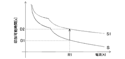
- FIG. 9 shows an overload characteristic graph of the entire system when corrected by the first correction method.
- FIG. 9 also shows the overload characteristic graph of the entire system before correction, for example, the overload characteristic graph S shown in FIG. 8B.
- the overload characteristic graph S1 of the whole system after correction is compared with the overload characteristic graph S of the whole system before correction.
- the application possible time is long. For example, when a current of 250% of the rated current is applied, the applicable time is about 0.9 seconds in the overload characteristic graph S of the entire system before correction, whereas In the overload characteristic graph S1, the applicable time is about 10 seconds.
- the applicable time is about 0.2 seconds in the overload characteristic graph S of the entire system before correction, whereas the load time of the entire system after correction is In the overload characteristic graph S1, the application possible time is about 2 seconds.
- the setting unit 120 basically does not change the shapes of the overload characteristic graphs of the motor 2 and the driver 4 before correction, and the ambient temperature and the ambient temperature of the motor 2 acquired in step S201.
- the ambient temperature of the driver 4 is used to move the asymptote of the overload characteristic graph.
- the setting unit 120 increases the rated current of the motor 2 and moves the asymptote so that the application possible time in the overload characteristic graph of the motor 2 becomes longer as the ambient temperature of the motor 2 becomes lower.
- the setting unit 120 increases the rated current of the driver 4 and moves the asymptote such that the lower the ambient temperature of the driver 4, the longer the applicable time in the overload characteristic graph of the driver 4.
- the setting unit 120 synthesizes the overload characteristic graph of the motor 2 and the overload characteristic graph of the driver 4 whose asymptote has been moved, and regenerates the overload characteristic graph of the entire system.
- FIG. 10 shows an overload characteristic graph of the entire system when corrected by the second correction method.
- FIG. 10 also shows the overload characteristic graph of the entire system before correction, for example, the overload characteristic graph S shown in FIG. 8B.
- the overload characteristic graph S2 of the whole system after the correction is compared with the overload characteristic graph S of the whole system before the correction. (R1 before correction, R2 after correction) is increased.
- the current value at which the application possible time is 100 seconds is a current value of about 130% of the rated current in the overload characteristic graph S of the whole system before correction, whereas the overload characteristic of the whole system after correction In graph S2, the current value is approximately 170% of the rated current.
- the current value at which the application possible time is 10 seconds is a current value of about 160% of the rated current in the overload characteristic graph S of the whole system before correction, whereas the overload characteristic of the whole system after correction In graph S2, the current value is approximately 230% of the rated current.
- the setting unit 120 determines the amount of movement (increase) of the asymptote based on the ambient temperature of the motor 2 and the ambient temperature of the driver 4 .
- the asymptote A of the overload characteristic graph S of the entire system before correction is a straight line that passes through a current value of 115% of the rated current among the straight lines parallel to the detection time axis.
- the insulation class of the motor 2 is F class
- the motor 2 is rated when the ambient temperature of the motor 2 is 40° C.
- the temperature of the motor 2 is set to be within 155° C., which is the allowable maximum temperature for the F class, even if 115% of the current is continuously applied.
- the current value of 115% of the rated current which is the current value of the asymptote A, is such a current value. Therefore, when the insulation class of the motor 2 is a class other than F class (for example, B class or H class), the current value of the asymptote is a current value other than 115% of the rated current.
- the insulation class of the motor 2 is Class F and the ambient temperature of the motor 2 is 0° C.
- the motor 2 has There is a temperature margin of 40°C.
- the temperature margin of 40°C corresponds to a current value margin of 29.68% of the rated current because a temperature of 1°C corresponds to a current value of 0.74% of the rated current in the case of the asymptote A. will do. That is, the setting unit 120 moves the asymptote A in the direction in which the current increases (to the right in FIG. 10) by a maximum current value of 29.68% of the rated current, to obtain the asymptote A2. be able to.
- the setting unit 120 moves the overload characteristic graph S of the entire system before correction in the direction in which the current increases, and sets the overload characteristic graph S2 of the entire system after correction. can be done.
- the specifications of the motor 2 stipulate the instantaneous allowable current value of the motor 2 . Therefore, even if the overload characteristic graph S of the entire system before correction is moved in the direction of increasing current, the setting unit 120 determines that the maximum current value of the overload characteristic graph exceeds the instantaneous allowable current value of the motor 2. In order to prevent this, the axial length indicating the current in the corrected overload characteristic graph S2 of the entire system is adjusted (shortened).
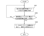
- FIG. 11 is a flowchart showing a second processing example of the electronic thermal unit 150.
- the overload determination units 110a and 100b receive thresholds corresponding to the corrected overload characteristic graphs of the motor 2 and the driver 4 from the setting unit 120 (applicable time for a predetermined current value larger than the rated current). ).
- the overload determination units 110a and 100b determine whether a current larger than the rated current has been applied to the motor 2 and the driver 4 for a period exceeding the applicable time.
- the overload determination unit 110a determines whether a current greater than the rated current is applied to the motor 2 beyond the application possible time for the motor 2, and the overload determination unit 110b determines whether the current greater than the rated current is applied to the driver 4 exceeding the application possible time for the driver 4. If it is determined that a current larger than the rated current has been applied to at least one of the motor 2 and the driver 4 for more than the applicable time, the process proceeds to step S303; otherwise, the process proceeds to step S301. proceed to At step 303, the overload determination section 110 outputs information indicating overload (abnormality or warning) assuming that the motor 2 and the driver 4 are overloaded. Information is output by light emission or flashing of an LED, output of a warning sound, display of information on a display, and the like.
- the setting unit 120 corrects the overload characteristic graphs of the motor 2 and the driver 4 based on the ambient temperature of the motor 2 and the ambient temperature of the driver 4, respectively.
- the overload determination unit 110 determines whether a current greater than the rated current has been applied to the motor 2 and the driver 4 beyond the applicable time based on the threshold value corresponding to the corrected overload characteristic graph. will be judged.
- the time that can be applied to the motor 2 and the driver 4 that is, by adjusting the load applied to the motor 2 and the driver 4, the motor 2 and the driver 4, the original performance of the IGBTs can be extracted as much as possible. Therefore, the motor 2 and the driver 4 can be efficiently used while protecting the motor 2 and the driver 4 .
- a current larger than the rated current is applied to each of the motor 2 and the driver 4 depending on the ambient temperature of the motor 2 and the driver. 4 can be applied up to the application possible time corresponding to the ambient temperature.
- the momentary allowable current value of the motor 2 will exceed the momentary allowable current value of the power cable 8 by applying a current larger than the rated current until the application possible time.
- Equation 6 K is a constant depending on the cable coating material
- Ac is the conductor cross-sectional area (mm 2 )
- Ts is the short circuit current duration (s).
- the allowable current for example, the rated current 300% current
- the momentary allowable current value I of the power cable 8 is 70.11A
- the momentary allowable current value I of the motor 2 for example, 41. 0A.
- the power cable 8 even if the power cable 8 is supplied with the instantaneous allowable current of the motor 2, the power cable 8 will not cause any problem.
- the threshold of the allowable current application time is increased to 1 second by correcting the overload characteristic graph of the motor 2 and the driver 4, the momentary allowable current value I of the power cable 8 becomes 38.4A.
- the momentary allowable current value of the motor 2 is exceeded.
- the temperature of the power cable 8 may rise excessively and burn out.
- the user can set the protection level of the power cable 8 by inputting the type of the power cable and the laying conditions of the power cable to the terminal 9 .
- the processor of the terminal 9 or the setting section 120 of the driver 4 calculates the protection level of the power cable 8 corresponding to the input information.
- ⁇ Cable coating material thermal resistance of coating material, or cable maximum operating temperature
- ⁇ Outer diameter and wire length of cable wire ⁇ Conductor material of cable wire, or electrical resistivity (resistivity, specific resistance) [ ⁇ m] ⁇ Cable wire conductor diameter (AWG, sq.) or cross-sectional area ⁇ Ambient temperature at the time of cable laying ⁇ In the case of multiple cable laying, multiple cable laying conditions ⁇ When wiring in a wiring duct, the material of the wiring duct, or the maximum operating temperature of the wiring duct material
- the terminal 9 displays the above menu on the display so that the user can select options or input numerical values.
- ⁇ Cable covering material (options: CV cable, OF cable, solid cable, vinyl cable) Or cable maximum operating temperature (option: 80°C, 85°C, 105°C)
- cable maximum operating temperature (option: 80°C, 85°C, 105°C)
- Cable wire conductor diameter (Enter value: AWG/SQ)
- Ambient temperature when laying cables (options: 0°C 25°C 40°C 55°C 70°C 85°C)
- Multiple laying (with or without)
- ⁇ Maximum operating temperature of wiring duct material when multiple lines are laid (options: 65°C, 80°C, 85°C, 105°C)
- the memory of the driver 4 (or the memory of the terminal 9 may be used) stores parameters (thermal resistances Ra to Rd, time constants Ta to Td, etc.) are stored, and the setting unit 120 acquires the parameter corresponding to the protection level acquired by its own calculation, or operates as a “reception unit” and acquires the parameter corresponding to the protection level from the terminal 9 to the calculation model 100a and 100b respectively.
- the values of the thermal resistances Ra to Rd are set so as to decrease as the conductor diameter of the cable wire increases.
- the values of the time constants Ta to Td are set to decrease as the number of multiple threads increases.
- the set of parameters may be calculated using an algorithm for calculating parameters based on the information entered.
- the setting unit 120 acquires the threshold value corresponding to the protection level, which is stored in advance in the memory, and sets it in each of the overload determination units 110a and 110b.
- thermal load calculation and overload determination of the motor 2 and the driver 4 can be performed in consideration of the power cable 8, and the motor 2 and the driver 4 can be efficiently operated while protecting the power cable 8 in addition to the motor 2 and the driver 4. can be used.
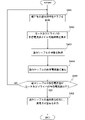
- FIG. 12 is a flowchart showing a third processing example of the electronic thermal unit 150.
- the overload determination units 100a and 100b acquire the corrected overload characteristic graphs of the motor 2 and the driver 4 from the setting unit 120, respectively.
- the overload determination units 100a and 100b determine the allowable current values of the motor 2 and the driver 4 from the corrected overload characteristic graphs of the motor 2 and the driver 4, and the applicable current values corresponding to the allowable current values. Calculate the time and
- step S ⁇ b>403 the overload determination units 100 a and 100 b acquire from the setting unit 120 the covering material type and conductor diameter of the cable as information on the configuration of the power cable 8 .
- the overload determination units 100a and 100b calculate the allowable current value of the power cable 8 from the calculated application possible time and the obtained information on the configuration of the power cable 8 using Equation 6.
- the overload determination units 100a and 100b determine whether the allowable current value of the power cable 8 is equal to or less than the allowable current values of the motor 2 and the driver 4. If the allowable current value of the power cable 8 is equal to or less than the allowable current values of the motor 2 and the driver 4, the process proceeds to step S406; otherwise, the process proceeds to step S401.
- the overload determination units 100a and 100b assume that the power cable 8 is overloaded and output information indicating overload (abnormality or warning). Information is output by light emission or flashing of an LED, output of a warning sound, display of information on a display, and the like.
- the overload determination unit 110 after correcting the overload characteristic graphs of the motor 2 and the driver 4, the overload determination unit 110, based on the corrected overload characteristic graphs of the motor 2 and the driver 4, It is determined whether the allowable current value of the power cable 8 is equal to or less than the allowable current values of the motor 2 and the driver 4, and when it is determined that the allowable current value of the power cable 8 is equal to or less than the allowable current values of the motor 2 and the driver 4 outputs information indicating overload.
- the allowable current value of the power cable 8 becomes lower than the allowable current values of the motor 2 and the driver 4, thereby avoiding the possibility that the temperature of the power cable 8 excessively rises and burns out. Therefore, the motor 2 and the driver 4 can be efficiently used while protecting not only the motor 2 and the driver 4 but also the power cable 8 .
- a load monitoring device (4) comprising:
Landscapes
- Engineering & Computer Science (AREA)
- Power Engineering (AREA)
- Control Of Electric Motors In General (AREA)
Abstract
負荷監視装置は、モータに関して該モータに供給される所定の電流値に対する印加可能時間を示す第1負荷特性を有する第1制御構造と、ドライバに関して所定の電流値に対する印加可能時間を示す第2負荷特性を有する第2制御構造とを有する負荷判定部と、モータの周囲温度である第1の周囲温度と、ドライバの周囲の温度である第2の周囲の温度とに基づいて、第1制御構造における第1負荷特性及び第2制御構造における第2負荷特性を補正する補正部と、を備える。
Description
本開示は、モータと、モータの動作制御を行うドライバの負荷を監視する負荷監視装置及び負荷監視方法に関する。
従来から、工作機械等で使用されるモータと、モータの動作制御を行うドライバに対する過熱保護のため、種々の方法が考えられてきた。例えば、特許文献1には、制御指示情報と温度センサが検出したモータの使用環境温度とを用いて制御テーブルを参照し、対応する制御量(モータトルク)を読み出してモータを制御する方法が記載されている。また、特許文献2には、モータに流した電流とモータからの放熱分とに基づいてモータの温度上昇分を求め、温度上昇分に基づいてモータの制御パラメータ(モータのトルク定数や抵抗値など)を補正する方法が記載されている。
しかし、特許文献1の方法では、制御テーブルによって必要以上のモータトルクを発生させないようにしており、モータの本来の性能を発揮できていない。また、特許文献2の方法では、制御パラメータの補正によって正確なモータのトルクを出力するようにしており、モータの本来の性能を発揮できていない。
本発明は、このような問題に鑑みてなされたものであり、その目的は、モータやドライバの本来の性能を可能な限り引き出すことができる負荷監視装置及び負荷監視方法を提供する。
本発明においては、上記課題を解決するために、モータと、モータの動作制御を行うドライバとの負荷を監視する負荷監視装置が、以下の構成を採用する。すなわち、負荷監視装置は、モータに供給される電流値を取得する電流値取得部と、電流値と前記モータの発熱量との関係を示す第1の熱モデルによってモータの温度を第1の温度として推定する第1の温度推定部と、電流値とドライバの発熱量との関係を示す第2の熱モデルによってドライバの温度を第2の温度として推定する第2の温度推定部と、第1の温度とモータ用の第1の閾値とを比較して該モータの過負荷状態の有無を判定するように構成され、該モータに関して所定の電流値に対する印加可能時間を示す第1負荷特性を有する第1制御構造と、第2の温度とドライバ用の第2の閾値とを比較して該ドライバの過負荷状態の有無を判定するように構成され、該ドライバに関して所定の電流値に対する印加可能時間を示す第2負荷特性を有する第2制御構造とを有する負荷判定部と、負荷判定部が、モータ又は前記ドライバの少なくとも一方が過負荷状態にあると判定した場合、過負荷状態に関する異常情報を出力する出力部と、モータの周囲温度である第1の周囲温度と、ドライバの周囲の温度である第2の周囲の温度とに基づいて、第1制御構造における第1負荷特性及び第2制御構造における第2負荷特性を補正する補正部と、を備えている。
本発明は、上記の負荷監視装置と同様の特徴を有する、負荷監視方法、負荷監視用のプログラム、そのようなプログラムを記録した記録媒体なども含む。
上記の構成によれば、モータの周囲温度及びドライバの周囲温度の夫々に基づいて、第1負荷特性及び第2負荷特性の夫々を補正する。これにより、補正後の負荷特性に対応する閾値に基づいて、モータ及びドライバに対して定格電流よりも大きい電流が印加可能時間を超過して印加されたかを判定するようになる。このようにして、モータ及びドライバに印加可能な時間を調整する、すなわちモータ及びドライバに掛かる負荷を調整することで、モータの周囲温度及びドライバの周囲温度に応じて、モータ及びドライバの本来の性能を可能な限り引き出すことができる。
上記の負荷監視装置では、補正部は、モータの定格電流を維持したまま第1の周囲温度が低くなるほど第1負荷特性における印加可能時間が長くなるように該第1負荷特性を補正し、ドライバの定格電流を維持したまま第2の周囲温度が低くなるほど第2負荷特性における印加可能時間が長くなるように該第2負荷特性を補正してもよい。
上記の構成によれば、第1負荷特性及び第2負荷特性の補正により、モータ及びドライバの夫々の定格電流を維持したまま、第1の周囲温度及び第2の周囲温度の夫々が低くなるほど第1負荷特性及び第2負荷特性の夫々における印加可能時間を長くすることができる。
上記の負荷監視装置では、補正部は、第1の周囲温度が低くなるほど、モータの定格電流を増加させるとともに第1負荷特性における印加可能時間が長くなるように該第1負荷特性を補正し、第2の周囲温度が低くなるほど、ドライバの定格電流を増加させるとともに第2負荷特性における印加可能時間が長くなるように該第2負荷特性を補正してもよい。
上記の構成によれば、第1負荷特性及び第2負荷特性の補正により、第1の周囲温度及び第2の周囲温度の夫々が低くなるほど、モータ及びドライバの夫々の定格電流を増加させるとともに、第1負荷特性及び第2負荷特性の夫々における印加可能時間を長くすることができる。
上記の負荷監視装置では、負荷判定部は、補正部によって補正された第1負荷特性及び第2負荷特性から、モータ及びドライバの許容電流値としての第1の電流値と、当該第1の電流値に対応する第1の印加可能時間とを算出し、第1の印加可能時間と、モータとドライバとを接続する動力ケーブルの構成に関する情報とから、当該動力ケーブルの許容電流値としての第2の電流値を算出し、第2の電流値と第1の電流値とを比較して、第2の電流値が第1の電流値以下であるときに動力ケーブルの過負荷状態を示す情報を出力してもよい。
上記の構成によれば、第1負荷特性及び第2負荷特性グラフを補正した後に、負荷判定部によって、補正後の第1負荷特性及び第2負荷特性に基づいて、動力ケーブルの許容電流値(第2の電流値)がモータ及びドライバの許容電流値(第1の電流値)以下であるかを判定し、第2の電流値が第1の電流値以下であるときには過負荷状態を示す情報を出力する。これにより、第2の電流値が第1の電流値を下回ることで、動力ケーブルの温度が過度に上昇して、焼損する可能性を回避することができる。このため、モータ及びドライバだけでなく動力ケーブルも保護しながら、モータ及びドライバの本来の性能を可能な限り引き出すことができる。
上記の負荷監視装置では、動力ケーブルの構成に関する情報の入力を受け付ける受付部、を更に備えてもよい。
上記の構成によれば、動力ケーブルの構成に関する情報を入力することができるようにすることで、動力ケーブルの種類や敷設条件に応じた好適な動力ケーブルの保護を図ることができる。
本発明によれば、モータやドライバの本来の性能を可能な限り引き出すことができる。
以下、図面に基づいて本願の実施形態に係る負荷監視装置について説明する。実施形態の構成は例示であり、実施形態の構成に限定されない。
<実施形態>
図1は、本実施形態の負荷監視装置としても作動するドライバ4を含む制御システムの概略構成図である。当該制御システムは、ネットワーク1と、モータ2と、負荷装置3と、ドライバ4と、PLC(Programmable Logic Controller)5と、動力ケーブル8と、端末9とを備える。
図1は、本実施形態の負荷監視装置としても作動するドライバ4を含む制御システムの概略構成図である。当該制御システムは、ネットワーク1と、モータ2と、負荷装置3と、ドライバ4と、PLC(Programmable Logic Controller)5と、動力ケーブル8と、端末9とを備える。
当該制御システムは、モータ2とともに負荷装置3を駆動制御するためのシステムである。そして、モータ2及び負荷装置3が、当該制御システムによって制御される制御対象6とされる。ここで、負荷装置3としては、各種の機械装置(例えば、産業用ロボットのアームや搬送装置)が例示できる。また、モータ2はその負荷装置3を駆動するアクチュエータとして負荷装置3内に組み込まれている。例えば、モータ2は、巻線が巻かれた固定子(ステータ)と回転子を有するACサーボモータである。モータ2は、その固定子に巻線が巻かれるとともに回転子を有する構成であればよく、その具体的な構成はACサーボモータに限定されない。
なお、モータ2には図示しないエンコーダが取り付けられており、当該エンコーダによりモータ2の動作に関するパラメータ信号がドライバ4にフィードバック送信されている。このフィードバック送信されるパラメータ信号(以下、フィードバック信号という)は、たとえばモータ2の回転軸の回転位置(角度)についての位置情報、その回転軸の回転速度の情報等を含む。
ドライバ4は、ネットワーク1を介してPLC5からモータ2の動作(モーション)に関する動作指令信号を受けるとともに、モータ2に接続されているエンコーダから出力されたフィードバック信号を受ける。ドライバ4は、PLC5からの動作指令信号およびエンコーダからのフィードバック信号に基づいて、モータ2の駆動に関するサーボ制御、すなわち、モータ2の動作に関する指令値を算出するとともに、モータ2の動作がその指令値に追従するように、モータ2に動力ケーブル8を介してu,v,wの3相の駆動電流を供給する。なお、モータ2に供給される駆動電流は、交流電源7からドライバ4に対して送られる交流電力が利用される。
本実施形態では、ドライバ4は三相交流を受けるタイプのものであるが、単相交流を受けるタイプのものでもよい。なお、ドライバ4によるサーボ制御については、ドライバ4が有する位置制御器41、速度制御器42、電流制御器43を利用したフィードバック制御である。
ここで、図1に示すように、ドライバ4は、位置制御器41、速度制御器42、電流制御器43を備え、これらの処理により上記サーボ制御が実行される。また、ドライバ4は、モータ2及びドライバ4を過熱による損傷から保護するために電子サーマル部150(図2を参照)を有している。
電子サーマル部150は、モータ2の巻線温度及びドライバ4の温度の夫々の温度を推定し、その推定温度に基づいてモータ2の過熱状態を判断する。
そこで、図2に示す、ドライバ4に形成される制御構造に基づいて、ドライバ4による上記サーボ制御及び電子サーマル部150によるモータ2の保護制御の説明を行う。当該制御構造は、所定の演算装置及びメモリ等を有するドライバ4において所定の制御プログラムが実行されることで形成される。
位置制御器41は、例えば、比例制御(P制御)を行う。具体的には、PLC5から通知された位置指令と検出位置との偏差である位置偏差に、位置比例ゲインKppを乗ずることにより速度指令を算出する。なお、位置制御器41は、予め制御パラメータとして、位置比例ゲインKppを有している。次に、速度制御器42は、例えば、比例積分制御(PI制御)を行う。具体的には、位置制御器41により算出された速度指令と検出速度との偏差である速度偏差の積分量に速度積分ゲインKviを乗じ、その算出結果と当該速度偏差の和に速度比例ゲインKvpを乗ずることにより、トルク指令を算出する。なお、速度制御器42は、予め制御パラメータとして、速度積分ゲインKviと速度比例ゲインKvpを有している。また、速度制御器42はPI制御に代えてP制御を行ってもよい。この場合には、速度制御器42は、予め制御パラメータとして、速度比例ゲインKvpを有することになる。次に、電流制御器43は、速度制御器42により算出されたトルク指令に基づいてアンプ44を駆動するための指令電圧を生成する。生成された指令電圧に応じてアンプ44がモータ2を駆動するための駆動電流を出力し、それによりモータ2が駆動制御される。電流制御器43は、トルク指令に関するフィルタ(1次のローパスフィルタ)や一又は複数のノッチフィルタを含み、制御パラメータとして、これらのフィルタの性能に関するカットオフ周波数等を有している。また、電流制御器43は、アンプ44からモータ2に供給される電流指令を検出する電流検出器を含み、電流検出器によって検出された電流指令が減算器にフィードバックされる。
そして、ドライバ4の制御構造は、速度制御器42、電流制御器43、制御対象6を前向き要素とする速度フィードバック系を含み、更に、当該速度フィードバック系と位置制御器41を前向き要素とする位置フィードバック系を含んでいる。このように構成される制御構造によって、ドライバ4はPLC5から供給される位置指令に追従するようにモータ2をサーボ制御することが可能となる。
このようにモータ2がサーボ制御される際に、モータ2に対して過大な負荷(例えば、モータ2の定格負荷を超える負荷)が比較的長時間掛けられると、モータ2の巻線に対して過大な電流が長時間流れることになる。これによって、巻線温度が過度に上昇し、その焼損を招く虞がある。また、ドライバ4からモータ2へ定格以上の電流が長時間供給されることで、ドライバ4又は動力ケーブル8の温度が過度に上昇し、焼損する虞もある。このような、モータ2、ドライバ4、及び動力ケーブル8の焼損などの損傷からこれらを保護するために、ドライバ4は電子サーマル部150を有している。
具体的には、電子サーマル部150は、算出モデル100と、過負荷判定部110とを有している。図3に示すように、算出モデル100は、モータ2用の算出モデル100aと、ドライバ4用の算出モデル100bとを含む。また、過負荷判定部110は、算出モデル100aに対応する、モータ2用の過負荷判定部110aと、算出モデル100bに対応する、ドライバ4用の過負荷判定部110bとを備える。
図4は、モータ2の算出モデル100aの概略構造を示している。算出モデル100aは、電子サーマル部150においてモータ2の巻線温度を算出するプログラムであり、その入力としてモータ2における熱流が与えられると、モータ2の巻線温度を出力する。なお、当該熱流は、モータ2の巻線コイルの電気抵抗に起因して生じる、いわゆる銅損とみなすことができ、巻線コイルを流れる電流の二乗に比例する。算出モデル100aは、モータ2に供給される電流値とモータ2の発熱量との関係を示す熱モデルであり、熱流は、例えば、算出モデル100が電力制御部43の指令電圧によりモータ2に供給される電流(電流指令)を検出することでその電流値を取得し、この電流値から単位時間当たりの熱量を求めることによって算出される。算出モデル100は、モータ2に供給される電流値を取得する電流値取得部として動作する。
図4に示すように、算出モデル100aは、算出モデル100a自身を構成するサブのモデルとして、巻線温度特性モデル101と固定子温度特性モデル102とを含む。巻線温度特性モデル101は、モータ2において仮想的に固定子の熱的影響を除いたときの、巻線の温度特性を算出するためのモデルである。
固定子温度特性モデル102は、基準モデル102’と、モータ2の回転子の回転速度(rpm)を引数とする鉄損係数Krとを含む。基準モデル102’は、モータ2において仮想的に巻線の熱的影響を除いたときの、固定子の温度特性を算出するためのモデルである。鉄損係数Krは、回転子の回転速度に応じてその数値が変動し得る。
固定子温度特性モデル102では、入力の熱流に(1+Kr)が乗じられたものが基準モデル102’に入力されて、固定子温度特性モデル102の出力が算出されることになる。算出モデル100aがこのような固定子温度特性モデル102を有することで、固定子の温度特性に回転子の回転に起因する鉄損を反映させることができ、過負荷保護のためのモータ2の巻線温度の推定をより好適に実現することができる。
このように、算出モデル100aが巻線温度特性モデル101と固定子温度特性モデル102とを含み、図4に示すように、各モデルの出力の和がモータ2の巻線温度として算出される。これによって、固定子と巻線との相関が考慮された上でモータの巻線温度が算出される。
ここで、巻線温度特性モデル101について説明する。巻線温度特性モデル101は、巻線の温度特性に関連するパラメータ(巻線関連パラメータ)である巻線に関する熱抵抗Raや熱時定数Taを含んで、下記の式1で表される。なお、熱抵抗Raは、熱の伝えにくさを表す値で、単位時間で発生する熱量あたりの温度上昇量を意味するパラメータである。本実施形態では、モータ2の巻線を熱的に均質な物体として捉えたときの熱抵抗が採用される。また、熱時定数Taは、巻線の温度変化に対する応答性の度合いを表すパラメータであり、巻線が初期の熱平衡状態から別の熱平衡状態に遷移する際に、その温度差の63.2%変化するのに要する時間として定義される。
巻線温度特性モデル = Ra/(Ta・s+1) ・・・(式1)
巻線温度特性モデル = Ra/(Ta・s+1) ・・・(式1)
次に、固定子温度特性モデル102について説明する。固定子温度特性モデル102の基準モデル102’は、固定子の温度特性に関連するパラメータ(固定子関連パラメータ)である固定子に関する熱抵抗Rbや熱時定数Tbを含んで、下記の式2で表される。なお、熱抵抗Rbの定義は上記の熱抵抗Raの定義と同じであり、本実施形態では、モータの固定子を熱的に均質な物体として捉えたときの熱抵抗が採用される。また、熱時定数Tbは、固定子の温度変化に対する応答性の度合いを表すパラメータであり、上記の熱時定数Taの定義と同じである。
固定子温度特性モデル = Rb/(Tb・s+1) ・・・(式2)
固定子温度特性モデル = Rb/(Tb・s+1) ・・・(式2)
そして、算出モデル100aにおいては、入力(モータ2における熱流)が、巻線温度特性モデル101及び固定子温度特性モデル102に引き渡される。そして、各モデルの出力が加算されて、算出モデルの出力、すなわちモータ巻線の推定温度とされる。なお、各モデル101、102の出力の加算の際に、各モデル101、102の出力に対して所定のゲインを乗じた値を加算するようにしてもよい。このように算出モデル100aが構成されることで、モータの巻線温度が固定子と巻線との相関を考慮して推定される。
図5は、ドライバ用の算出モデル100bの構成例を示す。算出モデル100bは、電子サーマル部150においてドライバ4の所定位置の温度特性を算出するためのモデルである。所定位置は、モータ2への電流の供給に応じて発熱する位置であればどこでもよく、例えば、ドライバ4が備えるIGBTや電流検出器などの所定の回路が実装された位置である。
図5に示すように、算出モデル100bは、算出モデル100b自身を構成するサブのモデルとして、検出抵抗部温度特性モデル103と基板部温度特性モデル104とを含む。検出抵抗部温度特性モデル103は、ドライバ4において仮想的にドライバ4の基板全体の熱的影響を除いたときの、電流検出器(電流検出抵抗)の温度特性を算出するためのモデルである。また、基板部温度特性モデル104は、ドライバ4において仮想的に電流検出抵抗の熱的影響を除いたときの、電流検出抵抗の周辺基板を含むドライバ4の基板全体の温度特性を算出するためのモデルである。
ここで、検出抵抗部温度特性モデル103について説明する。検出抵抗部温度特性モデル103は、検出抵抗部の温度特性に関連するパラメータ(検出抵抗部関連パラメータ)である電流検出抵抗に関する熱抵抗Rcや熱時定数Tcを含んで、下記の式3で表される。なお、熱抵抗Rcの定義は上記の熱抵抗Raの定義と同じであり、本実施形態では、電流検出抵抗を熱的に均質な物体として捉えたときの熱抵抗が採用される。また、熱時定数Tcは、電流検出抵抗の温度変化に対する応答性の度合いを表すパラメータであり、上記の熱時定数Taの定義と同じである。
検出抵抗部温度特性モデル = Rc/(Tc・s+1) ・・・(式3)
検出抵抗部温度特性モデル = Rc/(Tc・s+1) ・・・(式3)
次に、基板部温度特性モデル104について説明する。基板部温度特性モデル104は、基板部の温度特性に関連するパラメータ(基板部関連パラメータ)であるドライバ4の基板に関する熱抵抗Rdや熱時定数Tdを含んで、下記の式4で表される。なお、熱抵抗Rdの定義は上記の熱抵抗Raの定義と同じであり、本実施形態では、ドライバ4の基板全体を熱的に均質な物体として捉えたときの熱抵抗が採用される。また、熱時定数Tdは、ドライバ4の基板の温度変化に対する応答性の度合いを表すパラメータであり、上記の熱時定数Taの定義と同じである。
基板部温度特性モデル = Rd/(Td・s+1) ・・・(式4)
基板部温度特性モデル = Rd/(Td・s+1) ・・・(式4)
そして、算出モデル100bは、モータ2に供給される電流の値とドライバ4の発熱量との関係を示す熱モデルであり、アンプ44の出力として検出された電流(検出電流)に依存する熱流が入力として検出抵抗部温度特性モデル103及び基板部温度特性モデル104に引き渡される。そして、各モデルの出力が加算されて、算出モデルの出力、すなわちドライバ4の温度(「ドライバ温度」と称する)とされる。なお、各モデル103、104の出力の加算の際に、各モデル103、104の出力に対して所定のゲインを乗じた値を加算するようにしてもよい。このように算出モデル100bが構成されることで、ドライバ温度が電流検出抵抗と基板との相関を考慮して推定される。
上記の通り、算出モデル100a及び100bの夫々は、モータ2の温度及びドライバ温度の夫々を出力する。過負荷判定部110の過負荷判定部110aは、算出モデル100aの出力であるモータ2の温度(「モータ温度」と称する)に基づいて、モータ2が過負荷状態に至る可能性があるか、換言するとモータ2の巻線が過度に昇温するおそれがあるかについて判定を行う。
過負荷判定部110の過負荷判定部110bは、算出モデル100bの出力であるドライバ温度に基づいて、ドライバ4が過負荷状態に至る可能性があるか、換言するとドライバ4が全体的に又は局所的に過度に昇温するおそれがあるかについて判定を行う。
過負荷判定部110a及び110bによって、モータ2及びドライバ4のいずれか一つが過負荷状態に置かれていると判定された場合には、ドライバ4は、モータ2及びドライバ4を含む系を保護するためにその駆動を停止することができる。なお、算出モデル100は発熱量推定部に相当し、過負荷判定部110は負荷判定部及び出力部に相当する。
図6は、電子サーマル部150の第1の処理例を示すフローチャートである。ステップS101では、電子サーマル部150の算出モデル100a及び100bは、モータ温度及びドライバ温度を算出する。すなわち、算出モデル100aは、モータ2の熱負荷演算として熱流に応じたモータ温度(推定値)を演算する。算出モデル100bは、ドライバ4の熱負荷演算として熱流に応じたドライバ温度(推定値)を演算する。各温度の演算の順序は任意であり、並列に実行されてもよい。
ステップS102では、過負荷判定部110が、モータ温度及びドライバ温度のどちらかが閾値を超過するかを判定する。すなわち、過負荷判定部110aが、モータ温度がモータ2用の閾値を超過するかを判定し、過負荷判定部110bが、ドライバ温度がドライバ4用の閾値を超過するかを判定する。これらの判定の順序は任意であり、これらの判定は並列に実行されてもよい。どちらかの閾値の超過が判定された時点で、残りの判定が中止または停止されてもよい。モータ温度及びドライバ温度のどちらかが閾値を超過すると判定される場合、処理がステップS103に進み、そうでない場合には、処理がステップS101に進む。ここで、モータ2用の閾値とは、例えば、モータ2の絶縁階級から規定される許容最高温度である。例えば、モータ2の絶縁階級がF種である場合には、許容最高温度は155℃である。また、ドライバ4用の閾値とは、例えば、ドライバ4内のIGBTの保護のために設定される許容最高温度である。
ステップS103では、電子サーマル部150は、モータ2及びドライバ4の異常な温度上昇が検出されたものとして、モータ2及びドライバ4の過熱状態(異常や警告)を示す情報を出力する。情報は、LEDの発光または点滅、警告音の出力、ディスプレイへの情報の表示などによって出力される。出力を行う構成はドライバ4に設けられていてもよく、端末9が備えるディスプレイやスピーカを用いて情報が報知(表示等)されてもよい。また、電子サーマル部150は、異常・警告を示す情報の出力とともに、ドライバ4の動作を自動的に停止させる構成を有していてもよい。もっとも、ドライバ4の動作停止は、情報を受けたユーザがマニュアルで行ってもよい。
端末9は、ドライバ4が備える設定部120を通じて、ユーザが電子サーマル部150に各種の設定を行うために使用される。また、端末9は、上述した異常・警告を示す情報などの表示等によって、様々な情報をユーザに報知するために使用される。設定部120は、電子サーマル部150と同様に、ドライバ4が備えるプロセッサ(CPU)のプログラム実行によって実現されても、ドライバ4に実装された専用の回路(ハードウェア)によって実現されてもよい。
端末9は、プロセッサ、メモリ、入力装置、ディスプレイ、通信インタフェースなどを有している。プロセッサは、メモリに記憶されたプログラムの実行によって、メモリに対する情報の読み書き、ユーザが入力装置を用いて入力した情報の受け付け、或いはディスプレイへの表示、通信インタフェースの制御による設定部120との情報の送受信などを行う。
例えば、ユーザは、モータ2及びドライバ4の夫々に関する熱負荷演算のオンオフを操作することができる。すなわち、ユーザは、算出モデル100a及び100bの夫々のオン又はオフを示す情報を入力装置から端末9に入力することができる。
オン又はオフを示す情報は、ネットワーク1を介して設定部120に送られる。設定部120は、オン又はオフを示す情報に基づいて、対応する算出モデル100a及び100bのオンオフを行う。これによって、モータ2及びドライバ4の夫々に関する熱負荷演算のオンオフ(有効/無効の設定)を行うことができる。熱負荷演算のオフにより、プロセッサ(CPU)の演算負荷を下げることができる。
また、ドライバ4が有するメモリ(端末9が有するメモリでもよい)には、モータ2及びドライバ4の算出モデル100a及び100bに設定するパラメータ(熱抵抗Ra~Rd、時定数Ta~Tdなど)のセットが1又は2以上記憶されている。ユーザは、端末9で、モータ2及びドライバ4の夫々に関する熱負荷演算をオンにして、モータ2及びドライバ4の夫々の種別を入力することで、設定部120は、モータ2及びドライバ4の夫々の種別に対応するパラメータを算出モデル100a及び100bに設定し、モータ2及びドライバ4の夫々の種別に対応する閾値を過負荷判定部110a及び100bに設定する。
また、設定部120は、モータ2の稼働時間(通電時間)、或いはモータ2及びドライバ4の周囲温度に応じて、熱負荷演算のパラメータ(熱時定数など)及び閾値を自動的に変化させることができる。ドライバ4は、モータ2の稼働時間(通電時間)を計測しており、その計測値をパラメータ及び閾値の変化に使用することができる。また、周囲温度は、モータ2のエンコーダ内の温度センサの値やドライバ4内の放熱器の温度センサの値から予測してもよく、或いは、外気温を計測する温度センサの値を周囲温度として使用してもよい。
パラメータの変化の例として、稼働時間が所定時間を超える場合、設定部120は、熱時定数の値を基準値よりも小さくする。また、周囲温度が基準温度又は基準温度の範囲より高い場合には、設定部120は閾値を低下させる。逆に、周囲温度が基準温度の範囲より低い場合には、設定部120は閾値を上げる。このようにして、モータ2の使用状況に応じて、モータ2及びドライバ4を保護しつつモータ2を好適に使用することができる。
また、設定部120は、「制御部」として動作し、モータ2及びドライバ4用の熱負荷演算のパラメータ及び閾値を用いて、モータ2及びドライバ4の夫々に係るサーマル曲線(過負荷特性グラフ)を示す情報を生成及び出力することができる。更に、設定部120は、モータ2の過負荷特性グラフを示す情報とドライバ4の過負荷特性グラフを示す情報とを合成した情報を生成及び出力することができる。過負荷特性グラフは、定格電流より大きい電流が通電された場合における、過熱状態が検出されるまでの時間(検出時間)の変化を示すグラフである。過負荷特性は、通常、横軸に定格以上の電流をとり、縦軸に過負荷(過熱状態)が検出されるまでの時間(検出時間)をとったグラフで表される。なお、過負荷が検出されるまでの時間(検出時間)とは、定格電流より大きい所定の電流をモータ2及びドライバ4に継続して印加することが許可される時間(印加可能時間)であると言える。このことから、以下の過負荷特性グラフでは縦軸に検出時間の代わりに印加可能時間をとっている。
図7Aは、モータ2の過負荷特性を示すグラフMと、ドライバ4の過負荷特性を示すグラフDとを示す。過負荷特性グラフは、電流が大きくなる程、印加可能時間が短くなる。グラフM及びDの元になる数値は、ドライバ4において生成されてもよく、端末9において生成されてもよい。端末9のプロセッサは、グラフM及びDを端末9のディスプレイに表示する。これによって、ユーザは、モータ2及びドライバ4の夫々の過負荷特性を把握することができる。また、図7Bは、モータ2の過負荷特性を示すグラフMとドライバ4の過負荷特性を示すグラフDとを合成したグラフSを示す。端末9のプロセッサは、グラフSを端末9のディスプレイに表示する。これによって、ユーザは、モータ2及びドライバ4の両方の過負荷特性を満たす、モータ2及びドライバ4を含む系全体の過負荷特性を把握することができる。
また、設定部120は、モータ2の周囲温度としてエンコーダ内の温度センサの値と、ドライバ4の周囲温度としてドライバ4の放熱器の温度センサの値とを用いて、モータ2及びドライバ4の夫々の過負荷特性グラフを補正することができる。
図8は、設定部120の処理例を示すフローチャートである。この処理例では、初期状態として、図7に示すようなモータ2及びドライバ4の夫々の過負荷特性グラフM及びD、及び系全体の過負荷特性グラフSが生成されているものとする。ステップS201では、設定部120は、エンコーダ内の温度センサ及び放熱器の温度センサからモータ2の周囲温度及びドライバ4の周囲温度を取得する。
ステップS202では、設定部120は、ステップS201で取得したモータ2の周囲温度及びドライバ4の周囲温度の夫々に基づいて、モータ2及びドライバ4の夫々の過負荷特性グラフを補正する。そして、ステップS203では、設定部120は、ステップS203で補正したモータ2及びドライバ4の夫々の過負荷特性グラフに対応するパラメータを算出モデル100a及び100bの夫々に設定し、閾値を過負荷判定部110a及び100bの夫々に設定する。
ここで、ステップS202で行う過負荷特性グラフの補正について説明する。
まず、過負荷特性グラフの生成方法について説明する。ここでは、モータ2の過負荷特性グラフMの生成方法を例にして説明する。まず、設定部120は、過負荷特性グラフMを生成するための第1の電圧印加を行うための指令を電流制御器43に出力する。第1の電圧印加では、モータ2の定格電流の200%の電流をモータ2に供給する電圧印加を行う。そして、設定部120は、第1の電圧印加(通電)を行ってから3秒後、10秒後及び20秒後の夫々のモータ2の周囲温度を算出する。通電後のモータ2の周囲温度は、下記の式5で表される銅の抵抗温度係数を用いた抵抗法によって算出される。
t2 = (R2/R1-1)(234.5+t1)±Δt ・・・(式5)
式5において、R1は通電開始時のモータ2の巻線抵抗値であり、R2は通電後のモータ2の巻線抵抗値である。これらの巻線抵抗値は、電流検出器で検出された電流値から算出される。また、t1は通電開始時のモータ2の周囲温度であり、t2は通電後のモータ2の周囲温度である。ここでは、t1には、エンコーダ内の温度センサの値が使用される。そして、Δtは、通電開始時と通電後のモータ2の周囲温度の変化分である。Δtには、エンコーダ内の温度センサの値が使用される。通電後に周囲温度が上がったときにはΔtだけ減算され、周囲温度が下がったときにはΔtだけ加算される。
t2 = (R2/R1-1)(234.5+t1)±Δt ・・・(式5)
式5において、R1は通電開始時のモータ2の巻線抵抗値であり、R2は通電後のモータ2の巻線抵抗値である。これらの巻線抵抗値は、電流検出器で検出された電流値から算出される。また、t1は通電開始時のモータ2の周囲温度であり、t2は通電後のモータ2の周囲温度である。ここでは、t1には、エンコーダ内の温度センサの値が使用される。そして、Δtは、通電開始時と通電後のモータ2の周囲温度の変化分である。Δtには、エンコーダ内の温度センサの値が使用される。通電後に周囲温度が上がったときにはΔtだけ減算され、周囲温度が下がったときにはΔtだけ加算される。
次に、設定部120は、通電してから3秒後、10秒後及び20秒後の3点のモータ2の周囲温度t2の結果から、この3点を通る第1の電圧印加時の過負荷率の曲線を生成する。そして、設定部120は、この過負荷率の曲線から、モータ2の巻線に関する熱時定数Taと、固定子に関する熱時定数Tbと、熱時定数Taと熱時定数Tbとの比である熱抵抗比時定数とを算出する。
次に、設定部120は、第2の電圧印加を行うための指令を電流制御器43に出力する。第2の電圧印加では、モータ2の定格電流の300%の電流をモータ2に供給する電圧印加を行う。そして、設定部120は、第2の電圧印加(通電)を行ってから3秒後のモータ2の周囲温度t2を算出する。通電後のモータ2の周囲温度t2は、前述した式5で表される抵抗法によって算出される。
次に、設定部120は、第1の電圧印加の結果から算出した熱時定数Ta、熱時定数Tb及び熱抵抗比時定数Trから、第2の電圧印加時の過負荷率の曲線を生成する。なお、設定部120は、第2の電圧印加から3秒後のモータ2の周囲温度t2とモータ2用の閾値とに基づいて、生成した第2の電圧印加時の過負荷率の曲線が適正であるかどうかを確認してもよい。
そして、設定部120は、第1の電圧印加時の過負荷率の曲線と第2の電圧印加時の過負荷率の曲線とを合成して、モータ2の過負荷特性グラフMを得る。
また、ドライバ4の過負荷特性グラフDの生成は、モータ2の過負荷特性グラフMの生成と同様に式5を用いて行う。但し、式5において、R1は通電開始時のドライバ4の電流検出抵抗値であり、R2は通電後のドライバ4の電流検出抵抗値である。これらの電流検出抵抗値は、電流検出器で検出された電流値から算出される。t1は通電開始時のドライバ4の周囲温度であり、t2は通電後のドライバ4の周囲温度である。ここでは、t1には、ドライバ4内の放熱器の温度センサの値が使用される。そして、Δtは、通電開始時と通電後とのドライバ4の周囲温度の変化分である。Δtには、放熱器の温度センサの値が使用される。また、設定部120は、第1の電圧印加時の過負荷率の曲線から、ドライバ4の検出抵抗部に関する熱時定数Tcと、基板部に関する熱時定数Tdと、熱時定数Tcと熱時定数Tdとの比である熱抵抗比時定数とを算出する。なお、設定部120は、設定部120は、第2の電圧印加から3秒後のモータ2の周囲温度t2とドライバ4用の閾値とに基づいて、生成した第2の電圧印加時の過負荷率の曲線が適正であるかどうかを確認してもよい。
続いて、過負荷特性グラフの補正方法について説明する。第1の補正方法では、設定部120は、ステップS201で取得したモータ2の周囲温度及びドライバ4の周囲温度を用いて、モータ2及びドライバ4の夫々の過負荷特性グラフを再生成する。この再生成では、設定部120は、モータ2の定格電流を維持したままモータ2の周囲温度が低くなるほどモータ2の過負荷特性グラフにおける印加可能時間が長くなるように、モータ2の過負荷特性グラフを補正する。また、設定部120は、ドライバ4の定格電流を維持したままドライバ4の周囲温度が低くなるほどドライバ4の過負荷特性グラフにおける印加可能時間が長くなるように、ドライバ4の過負荷特性グラフを補正する。そして、設定部120は、再生成したモータ2の過負荷特性グラフとドライバ4の過負荷特性グラフとを合成して、系全体の過負荷特性グラフを再生成する。
図9は、第1の補正方法で補正した場合の系全体の過負荷特性グラフを示す。図9では、補正後の系全体の過負荷特性グラフに加えて、補正前の系全体の過負荷特性グラフ、例えば、図8Bに示す過負荷特性グラフSを併せて示す。図9に示すように、補正後の系全体の過負荷特性グラフS1は、補正前の系全体の過負荷特性グラフSと比べると、定格電流より大きい所定の電流値(R1)で比較したときに印加可能時間(補正前ではD1、補正後ではD2)が長くなっている。例えば、定格電流の250%の電流が通電された場合には、補正前の系全体の過負荷特性グラフSでは印加可能時間が約0・9秒であるのに対し、補正後の系全体の過負荷特性グラフS1では印加可能時間が約10秒となる。また、定格電流の350%の電流が通電された場合には、補正前の系全体の過負荷特性グラフSでは印加可能時間が約0.2秒であるのに対し、補正後の系全体の過負荷特性グラフS1では印加可能時間が約2秒となる。
また、第2の補正方法では、設定部120は、補正前のモータ2及びドライバ4の夫々の過負荷特性グラフの形状を基本的に変えずに、ステップS201で取得したモータ2の周囲温度及びドライバ4の周囲温度を用いて、過負荷特性グラフの漸近線を移動させる。この移動では、設定部120は、モータ2の定格電流を増加させるとともに、モータ2の周囲温度が低くなるほどモータ2の過負荷特性グラフにおける印加可能時間が長くなるように、漸近線を移動させる。また、設定部120は、ドライバ4の定格電流を増加させるとともに、ドライバ4の周囲温度が低くなるほどドライバ4の過負荷特性グラフにおける印加可能時間が長くなるように、漸近線を移動させる。そして、設定部120は、漸近線を移動させたモータ2の過負荷特性グラフとドライバ4の過負荷特性グラフとを合成して、系全体の過負荷特性グラフを再生成する。
図10は、第2の補正方法で補正した場合の系全体の過負荷特性グラフを示す。図10では、補正後の系全体の過負荷特性グラフに加えて、補正前の系全体の過負荷特性グラフ、例えば、図8Bに示す過負荷特性グラフSを併せて示す。図10に示すように、補正後の系全体の過負荷特性グラフS2は、補正前の系全体の過負荷特性グラフSと比べると、所定の印加可能時間(D1)で比較したときに電流値(補正前ではR1、補正後ではR2)が大きくなっている。例えば、印加可能時間が100秒となる電流値は、補正前の系全体の過負荷特性グラフSでは定格電流の約130%の電流値であるのに対し、補正後の系全体の過負荷特性グラフS2では定格電流の約170%の電流値となる。また、印加可能時間が10秒となる電流値は、補正前の系全体の過負荷特性グラフSでは定格電流の約160%の電流値であるのに対し、補正後の系全体の過負荷特性グラフS2では定格電流の約230%の電流値となる。
第2の補正方法において、設定部120は、モータ2の周囲温度及びドライバ4の周囲温度に基づいて漸近線の移動量(増加量)を決定する。例えば、補正前の系全体の過負荷特性グラフSの漸近線Aは、検出時間を示す軸と平行な直線のうちの定格電流の115%の電流値を通る直線である。例えば、モータ2の絶縁階級がF種である場合には、モータ2の周囲温度が40℃(モータ2の仕様から規定される使用環境温度の範囲の上限値)であるときにモータ2に定格電流の115%の電流を通電し続けても、モータ2の温度は、F種の許容最高温度である155℃以内に収まるように設定されている。漸近線Aの電流値である定格電流の115%の電流値とは、このような電流値である。従って、モータ2の絶縁階級がF種以外の種別(例えば、B種やH種など)である場合には、漸近線の電流値は定格電流の115%以外の電流値となる。ここで、モータ2の絶縁階級がF種である場合に、モータ2の周囲温度が0℃(モータ2の仕様から規定される使用環境温度の範囲の下限値)であるときには、モータ2には40℃の温度の余裕があることになる。40℃の温度の余裕とは、漸近線Aの場合には1℃の温度が定格電流の0.74%の電流値に相当するので、定格電流の29.68%の電流値の余裕に相当することになる。つまり、設定部120は、漸近線Aを、最大で定格電流の29.68%の電流値の分だけ、電流が増える方向(図10では、右方向)に移動させて、漸近線A2とすることができる。この漸近線Aの移動に伴い、設定部120は、補正前の系全体の過負荷特性グラフSを、電流が増える方向に移動させて、補正後の系全体の過負荷特性グラフS2とすることができる。但し、モータ2の仕様から、モータ2の瞬時許容電流値が規定されている。このため、設定部120は、補正前の系全体の過負荷特性グラフSを、電流が増える方向に移動させたとしても、過負荷特性グラフの最大電流値がモータ2の瞬時許容電流値を超過しないように、補正後の系全体の過負荷特性グラフS2における電流を示す軸方向の長さを調整(短く)する。
図11は、電子サーマル部150の第2の処理例を示すフローチャートである。ステップS301では、過負荷判定部110a及び100bは、設定部120から補正後のモータ2及びドライバ4の夫々の過負荷特性グラフに対応する閾値(定格電流よりも大きい所定の電流値に対する印加可能時間)を取得する。ステップS302では、過負荷判定部110a及び100bは、モータ2及びドライバ4の夫々に対して定格電流よりも大きい電流が印加可能時間を超過して印加されたかを判定する。すなわち、過負荷判定部110aが、定格電流よりも大きい電流がモータ2用の印加可能時間を超過してモータ2に印加されたかを判定し、過負荷判定部110bが、定格電流よりも大きい電流がドライバ4用の印加可能時間を超過してドライバ4に印加されたかを判定する。モータ2及びドライバ4の少なくとも一方に、定格電流よりも大きい電流が印加可能時間を超過して印加されたと判定される場合、処理がステップS303に進み、そうではない場合には、処理がステップS301に進む。ステップ303では、過負荷判定部110は、モータ2及びドライバ4に過負荷が発生したものとして、過負荷(異常や警告)を示す情報を出力する。情報は、LEDの発光または点滅、警告音の出力、ディスプレイへの情報の表示などによって出力される。
本実施形態によれば、設定部120によって、モータ2の周囲温度及びドライバ4の周囲温度の夫々に基づいて、モータ2及びドライバ4の夫々の過負荷特性グラフを補正する。これにより、過負荷判定部110は、補正後の過負荷特性グラフに対応する閾値に基づいて、モータ2及びドライバ4に対して定格電流よりも大きい電流が印加可能時間を超過して印加されたかを判定するようになる。このようにして、モータ2及びドライバ4に印加可能な時間を調整する、すなわちモータ2及びドライバ4に掛かる負荷を調整することで、モータ2の周囲温度及びドライバ4の周囲温度に応じて、モータ2及びドライバ4のIGBTの本来の性能を可能な限り引き出すことができる。このため、モータ2及びドライバ4を保護しながら、モータ2及びドライバ4を効率良く使用することができる。
<変形例>
次に、変形例について説明する。本変形例は実施形態と同様の構成を有するため、主として相違点について説明する。
次に、変形例について説明する。本変形例は実施形態と同様の構成を有するため、主として相違点について説明する。
前述した実施形態では、モータ2及びドライバ4の夫々の過負荷特性グラフを補正することで、モータ2及びドライバ4の夫々に対して、定格電流よりも大きい電流を、モータ2の周囲温度及びドライバ4の周囲温度に応じた印加可能時間まで印加することができる。しかし、定格電流よりも大きい電流を印加可能時間まで印加することで、モータ2の瞬時許容電流値が動力ケーブル8の瞬時許容電流値よりも上回ってしまう可能性がある。
ここで、動力ケーブル8の瞬時許容電流値Iは、下記の式6で表される。

・・・(式6)
式6において、Kはケーブル被覆材種に応じた定数であり、Acは導体断面積(mm2)であり、Tsは短絡電流持続時間(s)である。例えば、動力ケーブル8がビニルケーブル(K=96)であり、導体断面積が0.5mm2であるときに、補正前のモータ2及びドライバ4の過負荷特性グラフにおいて許容電流(例えば、定格電流の300%の電流)の印加可能時間の閾値が0.3秒である場合には、動力ケーブル8の瞬時許容電流値Iは70.11Aとなり、モータ2の瞬時許容電流値(例えば、41.0A)よりも上回っているものとする。この場合には、仮に動力ケーブル8にモータ2の瞬時許容電流を通電させたとしても、動力ケーブル8には問題は生じない。しかし、モータ2及びドライバ4の過負荷特性グラフの補正により、許容電流の印加可能時間の閾値が1秒と長くなった場合には、動力ケーブル8の瞬時許容電流値Iは38.4Aとなり、モータ2の瞬時許容電流値を下回ってしまう。この場合には、動力ケーブル8にモータ2の瞬時許容電流を通電させたときには、動力ケーブル8の温度が過度に上昇して、焼損する虞がある。
・・・(式6)
式6において、Kはケーブル被覆材種に応じた定数であり、Acは導体断面積(mm2)であり、Tsは短絡電流持続時間(s)である。例えば、動力ケーブル8がビニルケーブル(K=96)であり、導体断面積が0.5mm2であるときに、補正前のモータ2及びドライバ4の過負荷特性グラフにおいて許容電流(例えば、定格電流の300%の電流)の印加可能時間の閾値が0.3秒である場合には、動力ケーブル8の瞬時許容電流値Iは70.11Aとなり、モータ2の瞬時許容電流値(例えば、41.0A)よりも上回っているものとする。この場合には、仮に動力ケーブル8にモータ2の瞬時許容電流を通電させたとしても、動力ケーブル8には問題は生じない。しかし、モータ2及びドライバ4の過負荷特性グラフの補正により、許容電流の印加可能時間の閾値が1秒と長くなった場合には、動力ケーブル8の瞬時許容電流値Iは38.4Aとなり、モータ2の瞬時許容電流値を下回ってしまう。この場合には、動力ケーブル8にモータ2の瞬時許容電流を通電させたときには、動力ケーブル8の温度が過度に上昇して、焼損する虞がある。
そこで、本変形例に係る負荷監視装置では、モータ2及びドライバ4の夫々の過負荷の監視に加えて、更に動力ケーブル8の過負荷も監視する。
本変形例では、ユーザは、端末9に、動力ケーブルの種別と、動力ケーブルの敷設条件を入力することで、動力ケーブル8の保護レベルを設定することができる。例えば、下記要件を幾つか入力すると、端末9のプロセッサ、又はドライバ4の設定部120が、入力された情報に対応する動力ケーブル8の保護レベルを算出する。
・ケーブル被覆材種, 被覆材の熱抵抗, 或いはケーブル最高使用温度
・ケーブル電線の外径と線長
・ケーブル電線の導体材質,或いは電気抵抗率(抵抗率、比抵抗)[Ω・m]
・ケーブル電線の導体径 (AWG, sq.)或いは断面積
・ケーブル敷設時の周囲温度
・多条布設の場合は多条敷設条件
・配線ダクトに配線する場合は配線ダクトの材質、或いは配線ダクト材の最高使用温度
・ケーブル被覆材種, 被覆材の熱抵抗, 或いはケーブル最高使用温度
・ケーブル電線の外径と線長
・ケーブル電線の導体材質,或いは電気抵抗率(抵抗率、比抵抗)[Ω・m]
・ケーブル電線の導体径 (AWG, sq.)或いは断面積
・ケーブル敷設時の周囲温度
・多条布設の場合は多条敷設条件
・配線ダクトに配線する場合は配線ダクトの材質、或いは配線ダクト材の最高使用温度
例えば、端末9はディスプレイに上記のメニューを表示して、ユーザが選択肢の選択又は数値の入力をすることを可能に構成する。
・ケーブル被覆材種 (選択肢:CVケーブル、OFケーブル、ソリッドケーブル、ビニルケーブル)
或いはケーブル最高使用温度 (選択肢:80℃, 85℃, 105℃)
・ケーブル電線の導体径 (値を入力:AWG/SQ)
・ケーブル敷設時の周囲温度 (選択肢:0℃ 25℃ 40℃ 55℃ 70℃ 85℃)
・多条敷設 (あり なし)
・多条敷設ありの場合の配線ダクト材の最高使用温度 (選択肢:65℃, 80℃, 85℃, 105℃)
・ケーブル被覆材種 (選択肢:CVケーブル、OFケーブル、ソリッドケーブル、ビニルケーブル)
或いはケーブル最高使用温度 (選択肢:80℃, 85℃, 105℃)
・ケーブル電線の導体径 (値を入力:AWG/SQ)
・ケーブル敷設時の周囲温度 (選択肢:0℃ 25℃ 40℃ 55℃ 70℃ 85℃)
・多条敷設 (あり なし)
・多条敷設ありの場合の配線ダクト材の最高使用温度 (選択肢:65℃, 80℃, 85℃, 105℃)
ドライバ4が有するメモリ(端末9が有するメモリでもよい)には、保護レベルに対応するモータ2及びドライバ4の算出モデル100a及び100bの夫々に設定するパラメータ(熱抵抗Ra~Rd、時定数Ta~Tdなど)のセットが1又は2以上記憶されており、設定部120は、自身による算出によって取得、又は「受付部」として動作して端末9から取得した保護レベルに対応するパラメータを算出モデル100a及び100bの夫々に設定する。例えば、熱抵抗Ra~Rdの値は、ケーブル電線の導体径が太くなるほど小さくなるように設定される。また、例えば、時定数Ta~Tdの値は、多条数が増えるにつれて小さくなるように設定される。パラメータのセットは入力された情報に基づいて、パラメータ算出用のアルゴリズムを用いて計算されてもよい。また、予めメモリに記憶された、保護レベルに対応する閾値を設定部120は取得し、過負荷判定部110a及び110bの夫々に設定する。これによって、動力ケーブル8を考慮したモータ2及びドライバ4の熱負荷演算及び過負荷判定が可能となり、モータ2及びドライバ4に加えて動力ケーブル8を保護しながら、モータ2及びドライバ4を効率良く使用することができる。
図12は、電子サーマル部150の第3の処理例を示すフローチャートである。ステップS401では、過負荷判定部100a及び100bは、設定部120から補正後のモータ2及びドライバ4の夫々の過負荷特性グラフを取得する。ステップS402では、過負荷判定部100a及び100bは、補正後のモータ2及びドライバ4の夫々の過負荷特性グラフから、モータ2及びドライバ4の許容電流値と、当該許容電流値に対応する印加可能時間とを算出する。ステップS403では、過負荷判定部100a及び100bは、設定部120から動力ケーブル8の構成に関する情報としてケーブルの被覆材種及び導体径を取得する。ステップ404では、過負荷判定部100a及び100bは、式6を用いて、算出した印加可能時間と、取得した動力ケーブル8の構成に関する情報とから、動力ケーブル8の許容電流値を算出する。ステップS405では、過負荷判定部100a及び100bは、動力ケーブル8の許容電流値がモータ2及びドライバ4の許容電流値以下であるかを判定する。動力ケーブル8の許容電流値がモータ2及びドライバ4の許容電流値以下である場合、処理はステップS406に進み、そうではない場合には、処理がステップS401に進む。ステップS406では、過負荷判定部100a及び100bは、動力ケーブル8に過負荷が発生するものとして、過負荷(異常や警告)を示す情報を出力する。情報は、LEDの発光または点滅、警告音の出力、ディスプレイへの情報の表示などによって出力される。
本変形例によれば、モータ2及びドライバ4の夫々の過負荷特性グラフを補正した後に、過負荷判定部110によって、補正後のモータ2及びドライバ4の夫々の過負荷特性グラフに基づいて、動力ケーブル8の許容電流値がモータ2及びドライバ4の許容電流値以下であるかを判定し、動力ケーブル8の許容電流値がモータ2及びドライバ4の許容電流値以下であると判定した場合には過負荷を示す情報を出力する。これにより、動力ケーブル8の許容電流値がモータ2及びドライバ4の許容電流値を下回ることで、動力ケーブル8の温度が過度に上昇して、焼損する可能性を回避することができる。このため、モータ2及びドライバ4だけでなく動力ケーブル8も保護しながら、モータ2及びドライバ4を効率良く使用することができる。
<付記>
モータ(2)と、前記モータ(2)の動作制御を行うドライバ(4)との負荷を監視する負荷監視装置(4)であって、
前記モータ(2)に供給される電流値を取得する電流値取得部(150)と、
前記電流値と前記モータ(2)の発熱量との関係を示す第1の熱モデル(100a)によって前記モータ(2)の温度を第1の温度として推定する第1の温度推定部(100)と、
前記電流値と前記ドライバ(4)の発熱量との関係を示す第2の熱モデル(100b)によって前記ドライバ(4)の温度を第2の温度として推定する第2の温度推定部(100)と、
前記第1の温度と前記モータ(2)用の第1の閾値とを比較して該モータ(2)の過負荷状態の有無を判定するように構成され、該モータ(2)に関して所定の前記電流値に対する印加可能時間を示す第1負荷特性(M)を有する第1制御構造と、前記第2の温度と前記ドライバ(4)用の第2の閾値とを比較して該ドライバ(4)の過負荷状態の有無を判定するように構成され、該ドライバ(4)に関して所定の前記電流値に対する印加可能時間を示す第2負荷特性(D)を有する第2制御構造とを有する負荷判定部(110)と、
前記負荷判定部が、前記モータ(2)又は前記ドライバ(4)の少なくとも一方が過負荷状態にあると判定した場合、過負荷状態に関する異常情報を出力する出力部(100)と、
前記モータ(2)の周囲温度である第1の周囲温度と、前記ドライバ(4)の周囲の温度である第2の周囲の温度とに基づいて、前記第1制御構造における前記第1負荷特性(M)及び前記第2制御構造における前記第2負荷特性(D)を補正する補正部(120)と、
を備える、負荷監視装置(4)。
モータ(2)と、前記モータ(2)の動作制御を行うドライバ(4)との負荷を監視する負荷監視装置(4)であって、
前記モータ(2)に供給される電流値を取得する電流値取得部(150)と、
前記電流値と前記モータ(2)の発熱量との関係を示す第1の熱モデル(100a)によって前記モータ(2)の温度を第1の温度として推定する第1の温度推定部(100)と、
前記電流値と前記ドライバ(4)の発熱量との関係を示す第2の熱モデル(100b)によって前記ドライバ(4)の温度を第2の温度として推定する第2の温度推定部(100)と、
前記第1の温度と前記モータ(2)用の第1の閾値とを比較して該モータ(2)の過負荷状態の有無を判定するように構成され、該モータ(2)に関して所定の前記電流値に対する印加可能時間を示す第1負荷特性(M)を有する第1制御構造と、前記第2の温度と前記ドライバ(4)用の第2の閾値とを比較して該ドライバ(4)の過負荷状態の有無を判定するように構成され、該ドライバ(4)に関して所定の前記電流値に対する印加可能時間を示す第2負荷特性(D)を有する第2制御構造とを有する負荷判定部(110)と、
前記負荷判定部が、前記モータ(2)又は前記ドライバ(4)の少なくとも一方が過負荷状態にあると判定した場合、過負荷状態に関する異常情報を出力する出力部(100)と、
前記モータ(2)の周囲温度である第1の周囲温度と、前記ドライバ(4)の周囲の温度である第2の周囲の温度とに基づいて、前記第1制御構造における前記第1負荷特性(M)及び前記第2制御構造における前記第2負荷特性(D)を補正する補正部(120)と、
を備える、負荷監視装置(4)。
1・・・ネットワーク
2・・・モータ
3・・・負荷装置
4・・・ドライバ
5・・・PLC
6・・・制御対象
7・・・交流電源
8・・・動力ケーブル
9・・・端末
41・・・位置制御器
42・・・速度制御器
43・・・電流制御器
44・・・アンプ
100・・・算出モデル
110・・・過負荷判定部
120・・・設定部
150・・・電子サーマル部
2・・・モータ
3・・・負荷装置
4・・・ドライバ
5・・・PLC
6・・・制御対象
7・・・交流電源
8・・・動力ケーブル
9・・・端末
41・・・位置制御器
42・・・速度制御器
43・・・電流制御器
44・・・アンプ
100・・・算出モデル
110・・・過負荷判定部
120・・・設定部
150・・・電子サーマル部
Claims (6)
- モータと、前記モータの動作制御を行うドライバとの負荷を監視する負荷監視装置であって、
前記モータに供給される電流値を取得する電流値取得部と、
前記電流値と前記モータの発熱量との関係を示す第1の熱モデルによって前記モータの温度を第1の温度として推定する第1の温度推定部と、
前記電流値と前記ドライバの発熱量との関係を示す第2の熱モデルによって前記ドライバの温度を第2の温度として推定する第2の温度推定部と、
前記第1の温度と前記モータ用の第1の閾値とを比較して該モータの過負荷状態の有無を判定するように構成され、該モータに関して所定の前記電流値に対する印加可能時間を示す第1負荷特性を有する第1制御構造と、前記第2の温度と前記ドライバ用の第2の閾値とを比較して該ドライバの過負荷状態の有無を判定するように構成され、該ドライバに関して所定の前記電流値に対する印加可能時間を示す第2負荷特性を有する第2制御構造とを有する負荷判定部と、
前記負荷判定部が、前記モータ又は前記ドライバの少なくとも一方が過負荷状態にあると判定した場合、過負荷状態に関する異常情報を出力する出力部と、
前記モータの周囲温度である第1の周囲温度と、前記ドライバの周囲の温度である第2の周囲の温度とに基づいて、前記第1制御構造における前記第1負荷特性及び前記第2制御構造における前記第2負荷特性を補正する補正部と、
を備える、負荷監視装置。 - 前記補正部は、前記モータの定格電流を維持したまま前記第1の周囲温度が低くなるほど前記第1負荷特性における前記印加可能時間が長くなるように該第1負荷特性を補正し、前記ドライバの定格電流を維持したまま前記第2の周囲温度が低くなるほど前記第2負荷特性における前記印加可能時間が長くなるように該第2負荷特性を補正する、
請求項1に記載の負荷監視装置。 - 前記補正部は、前記第1の周囲温度が低くなるほど、前記モータの定格電流を増加させるとともに前記第1負荷特性における前記印加可能時間が長くなるように該第1負荷特性を補正し、前記第2の周囲温度が低くなるほど、前記ドライバの定格電流を増加させるとともに前記第2負荷特性における前記印加可能時間が長くなるように該第2負荷特性を補正する、
請求項1に記載の負荷監視装置。 - 前記負荷判定部は、前記補正部によって補正された前記第1負荷特性及び前記第2負荷特性から、前記モータ及び前記ドライバの許容電流値としての第1の電流値と、当該第1の電流値に対応する第1の印加可能時間とを算出し、前記第1の印加可能時間と、前記モータと前記ドライバとを接続する動力ケーブルの構成に関する情報とから、当該動力ケーブルの許容電流値としての第2の電流値を算出し、前記第2の電流値と前記第1の電流値とを比較して、前記第2の電流値が前記第1の電流値以下であるときに前記動力ケーブルの過負荷状態を示す情報を出力する、
請求項1から請求項3の何れか1項に記載の負荷監視装置。 - 前記動力ケーブルの構成に関する情報の入力を受け付ける受付部、
を更に備えた、
請求項4に記載の負荷監視装置。 - モータと、前記モータの動作制御を行うドライバとの負荷を監視する負荷監視方法であって、
前記モータに供給される電流値を取得し、
前記電流値と前記モータの発熱量との関係を示す第1の熱モデルによって前記モータの温度を第1の温度として推定し、
前記電流値と前記ドライバの発熱量との関係を示す第2の熱モデルによって前記ドライバの温度を第2の温度として推定し、
前記モータに関して所定の前記電流値に対する印加可能時間を示す第1負荷特性を生成し、
前記第1の温度から前記モータ用の第1の閾値を補正し、
前記モータ用の補正した第1の閾値と現在の出力電流値を比較して該モータの過負荷状態の有無を判定し、
前記ドライバに関して所定の前記電流値に対する印加可能時間を示す第2負荷特性を生成し、
前記第2の温度から前記ドライバ用の第2の閾値を補正し、
前記ドライバ用の補正した第2の閾値と現在の出力電流値を比較して該ドライバの過負荷状態の有無を判定し、
前記モータ又は前記ドライバの少なくとも一方が過負荷状態にあると判定した場合、過負荷状態に関する異常情報を出力し、
前記モータの周囲温度である第1の周囲温度と、前記ドライバの周囲の温度である第2の周囲の温度とに基づいて、前記第1制御構造における前記第1負荷特性及び前記第2制御構造における前記第2負荷特性を補正する、
負荷監視方法。
Applications Claiming Priority (2)
| Application Number | Priority Date | Filing Date | Title |
|---|---|---|---|
| JP2021041879A JP7596869B2 (ja) | 2021-03-15 | 2021-03-15 | 負荷監視装置及び負荷監視方法 |
| JP2021-041879 | 2021-03-15 |
Publications (1)
| Publication Number | Publication Date |
|---|---|
| WO2022196002A1 true WO2022196002A1 (ja) | 2022-09-22 |
Family
ID=83320066
Family Applications (1)
| Application Number | Title | Priority Date | Filing Date |
|---|---|---|---|
| PCT/JP2021/047105 Ceased WO2022196002A1 (ja) | 2021-03-15 | 2021-12-20 | 負荷監視装置及び負荷監視方法 |
Country Status (2)
| Country | Link |
|---|---|
| JP (1) | JP7596869B2 (ja) |
| WO (1) | WO2022196002A1 (ja) |
Families Citing this family (1)
| Publication number | Priority date | Publication date | Assignee | Title |
|---|---|---|---|---|
| KR20250014754A (ko) | 2023-07-21 | 2025-02-03 | 현대트랜시스 주식회사 | 로봇 감속기의 진단장치 및 그 방법 |
Citations (4)
| Publication number | Priority date | Publication date | Assignee | Title |
|---|---|---|---|---|
| JP2002345147A (ja) * | 2001-05-15 | 2002-11-29 | Hitachi Ltd | モータ制御装置 |
| JP2003082409A (ja) * | 2001-09-12 | 2003-03-19 | Kawasaki Steel Corp | 攪拌用モータの回転数制御方法 |
| WO2016174867A1 (ja) * | 2015-04-27 | 2016-11-03 | パナソニックIpマネジメント株式会社 | モータの過負荷保護方法 |
| JP2018027611A (ja) * | 2016-08-10 | 2018-02-22 | 株式会社マキタ | 電動作業機 |
-
2021
- 2021-03-15 JP JP2021041879A patent/JP7596869B2/ja active Active
- 2021-12-20 WO PCT/JP2021/047105 patent/WO2022196002A1/ja not_active Ceased
Patent Citations (4)
| Publication number | Priority date | Publication date | Assignee | Title |
|---|---|---|---|---|
| JP2002345147A (ja) * | 2001-05-15 | 2002-11-29 | Hitachi Ltd | モータ制御装置 |
| JP2003082409A (ja) * | 2001-09-12 | 2003-03-19 | Kawasaki Steel Corp | 攪拌用モータの回転数制御方法 |
| WO2016174867A1 (ja) * | 2015-04-27 | 2016-11-03 | パナソニックIpマネジメント株式会社 | モータの過負荷保護方法 |
| JP2018027611A (ja) * | 2016-08-10 | 2018-02-22 | 株式会社マキタ | 電動作業機 |
Also Published As
| Publication number | Publication date |
|---|---|
| JP2022141526A (ja) | 2022-09-29 |
| JP7596869B2 (ja) | 2024-12-10 |
Similar Documents
| Publication | Publication Date | Title |
|---|---|---|
| CN111245323B (zh) | 电机控制方法、装置和计算机可读存储介质、电器设备 | |
| JP6493259B2 (ja) | 温度監視装置、温度監視方法、情報処理プログラム、および記録媒体 | |
| CN109845091B (zh) | 用于电机的温度降额的方法 | |
| CN103368499B (zh) | 通过推定的温度进行电动机过热保护的电动机控制装置 | |
| JP5474421B2 (ja) | モータ巻線焼損保護装置 | |
| JP6973311B2 (ja) | 処理装置 | |
| JP7388158B2 (ja) | 処理装置、及び巻線温度算出モデルの決定方法 | |
| US11353830B2 (en) | Servo control method | |
| JPH06508259A (ja) | 機関車の主牽引用交流機の熱保護 | |
| JP3668666B2 (ja) | 同期電動機とそれを用いた電気車及びその制御方法 | |
| JP7596869B2 (ja) | 負荷監視装置及び負荷監視方法 | |
| JP6360032B2 (ja) | モータ温度及びアンプ温度に応じて動作を変更する機能を有する工作機械の制御装置 | |
| CN107107238A (zh) | 用于提供具有热保护的辅助和焊接类型电源的方法和设备 | |
| JP3252114B2 (ja) | 電動モータの制御装置 | |
| WO2006114843A1 (ja) | サーボモータの制御装置 | |
| JP7631888B2 (ja) | 温度監視装置、及び温度監視方法 | |
| JP6413440B2 (ja) | モータ制御装置 | |
| JP5034914B2 (ja) | エレベータの制御装置 | |
| JP7594844B2 (ja) | 電力変換器の過熱保護制御装置 | |
| WO2016174867A1 (ja) | モータの過負荷保護方法 | |
| EP3351334A1 (en) | Methods and systems for visually displaying thermal duty cycles | |
| WO2022163493A1 (ja) | 温度保護装置および制御装置 | |
| JPH0471379A (ja) | モータの制御回路 | |
| CN115021532A (zh) | 一种功率器件的控制装置及方法 | |
| WO2022244084A1 (ja) | モータの制御方法及びモータの制御装置 |
Legal Events
| Date | Code | Title | Description |
|---|---|---|---|
| 121 | Ep: the epo has been informed by wipo that ep was designated in this application |
Ref document number: 21931744 Country of ref document: EP Kind code of ref document: A1 |
|
| NENP | Non-entry into the national phase |
Ref country code: DE |
|
| 122 | Ep: pct application non-entry in european phase |
Ref document number: 21931744 Country of ref document: EP Kind code of ref document: A1 |