WO2022195812A1 - 道路劣化診断装置、道路劣化診断方法、及び、記録媒体 - Google Patents
道路劣化診断装置、道路劣化診断方法、及び、記録媒体 Download PDFInfo
- Publication number
- WO2022195812A1 WO2022195812A1 PCT/JP2021/011139 JP2021011139W WO2022195812A1 WO 2022195812 A1 WO2022195812 A1 WO 2022195812A1 JP 2021011139 W JP2021011139 W JP 2021011139W WO 2022195812 A1 WO2022195812 A1 WO 2022195812A1
- Authority
- WO
- WIPO (PCT)
- Prior art keywords
- deterioration
- status
- road
- section
- detection
- Prior art date
- Legal status (The legal status is an assumption and is not a legal conclusion. Google has not performed a legal analysis and makes no representation as to the accuracy of the status listed.)
- Ceased
Links
Images







Classifications
-
- G—PHYSICS
- G06—COMPUTING OR CALCULATING; COUNTING
- G06Q—INFORMATION AND COMMUNICATION TECHNOLOGY [ICT] SPECIALLY ADAPTED FOR ADMINISTRATIVE, COMMERCIAL, FINANCIAL, MANAGERIAL OR SUPERVISORY PURPOSES; SYSTEMS OR METHODS SPECIALLY ADAPTED FOR ADMINISTRATIVE, COMMERCIAL, FINANCIAL, MANAGERIAL OR SUPERVISORY PURPOSES, NOT OTHERWISE PROVIDED FOR
- G06Q10/00—Administration; Management
- G06Q10/20—Administration of product repair or maintenance
-
- G—PHYSICS
- G01—MEASURING; TESTING
- G01C—MEASURING DISTANCES, LEVELS OR BEARINGS; SURVEYING; NAVIGATION; GYROSCOPIC INSTRUMENTS; PHOTOGRAMMETRY OR VIDEOGRAMMETRY
- G01C21/00—Navigation; Navigational instruments not provided for in groups G01C1/00 - G01C19/00
- G01C21/26—Navigation; Navigational instruments not provided for in groups G01C1/00 - G01C19/00 specially adapted for navigation in a road network
-
- G—PHYSICS
- G01—MEASURING; TESTING
- G01C—MEASURING DISTANCES, LEVELS OR BEARINGS; SURVEYING; NAVIGATION; GYROSCOPIC INSTRUMENTS; PHOTOGRAMMETRY OR VIDEOGRAMMETRY
- G01C21/00—Navigation; Navigational instruments not provided for in groups G01C1/00 - G01C19/00
- G01C21/26—Navigation; Navigational instruments not provided for in groups G01C1/00 - G01C19/00 specially adapted for navigation in a road network
- G01C21/34—Route searching; Route guidance
-
- G—PHYSICS
- G06—COMPUTING OR CALCULATING; COUNTING
- G06T—IMAGE DATA PROCESSING OR GENERATION, IN GENERAL
- G06T7/00—Image analysis
- G06T7/0002—Inspection of images, e.g. flaw detection
-
- G—PHYSICS
- G06—COMPUTING OR CALCULATING; COUNTING
- G06V—IMAGE OR VIDEO RECOGNITION OR UNDERSTANDING
- G06V20/00—Scenes; Scene-specific elements
- G06V20/50—Context or environment of the image
- G06V20/56—Context or environment of the image exterior to a vehicle by using sensors mounted on the vehicle
- G06V20/588—Recognition of the road, e.g. of lane markings; Recognition of the vehicle driving pattern in relation to the road
-
- G—PHYSICS
- G08—SIGNALLING
- G08G—TRAFFIC CONTROL SYSTEMS
- G08G1/00—Traffic control systems for road vehicles
-
- G—PHYSICS
- G06—COMPUTING OR CALCULATING; COUNTING
- G06T—IMAGE DATA PROCESSING OR GENERATION, IN GENERAL
- G06T2207/00—Indexing scheme for image analysis or image enhancement
- G06T2207/30—Subject of image; Context of image processing
- G06T2207/30181—Earth observation
- G06T2207/30184—Infrastructure
-
- G—PHYSICS
- G06—COMPUTING OR CALCULATING; COUNTING
- G06T—IMAGE DATA PROCESSING OR GENERATION, IN GENERAL
- G06T2207/00—Indexing scheme for image analysis or image enhancement
- G06T2207/30—Subject of image; Context of image processing
- G06T2207/30248—Vehicle exterior or interior
- G06T2207/30252—Vehicle exterior; Vicinity of vehicle
Definitions
- the present disclosure relates to a road deterioration diagnosis device, a road deterioration diagnosis method, and a recording medium.
- Patent Literature 1 discloses a road surface condition determination device that performs image processing on an image of a road surface and determines the condition of the road surface.
- Patent Literature 2 discloses a device that automatically detects a location requiring repair based on the detected road surface condition and displays it on a map.
- each detected road deterioration is displayed on a map. That is, each road deterioration is managed as a repair-required spot.
- business operators repeatedly drive vehicles in an area to detect road deterioration, such as potholes, in order to quickly discover road deterioration that requires early repair. For this reason, when road deterioration occurs in a concentrated manner in a narrow range, when each road deterioration is managed, it becomes necessary to manage a large number of road deteriorations in that range, which becomes complicated.
- Patent Literature 1 does not disclose managing road deterioration on a map.
- One of the objects of the present disclosure is to solve the above-described problems and to provide a road deterioration diagnosis device, a road deterioration diagnosis method, and a recording medium that can efficiently manage road deterioration in accordance with maintenance forms. .
- a first road deterioration diagnosis device for each section obtained by dividing a predetermined area into a predetermined size, determines the detection status of potholes in the section and the maintenance status of the detected potholes. and display control means for causing a display means to display a map showing the deterioration information in each of the sections.
- a second road deterioration diagnosis device is configured to determine, for each section obtained by dividing a predetermined area into a predetermined size, a detection state of road deterioration in the section and a maintenance state of the detected road deterioration.
- a storage means for storing deterioration information including road deterioration information; and when road deterioration is detected in a section in which the detection status is not yet detected, the detection status of the section is set to "detected", and according to the maintenance status of the road deterioration updating means for updating the maintenance status of the partition, and updating the detection status to undetected after a predetermined period of time has elapsed since the maintenance status was updated to a predetermined status; and the deterioration information in each partition. and display control means for causing the display means to display a map showing the.
- a road deterioration diagnosis method includes, for each section obtained by dividing a predetermined area into a predetermined size, deterioration information including the detection status of potholes in the section and the maintenance status of the detected potholes. is stored, and a display means displays a map showing the deterioration information in each of the sections.
- a recording medium stores, in a computer, for each section obtained by dividing a predetermined area into a predetermined size, deterioration including the detection status of potholes in the section and the maintenance status of the detected potholes
- a program for storing the information and causing the display means to display a map showing the deterioration information in each of the sections is recorded.
- the effect of the present disclosure is that road deterioration can be efficiently managed according to the type of maintenance.
- FIG. 1 is a block diagram showing the configuration of a road deterioration diagnosis system 10 in a first embodiment
- FIG. It is a block diagram showing an example of composition of road degradation diagnosis device 20 in a 1st embodiment. It is a figure which shows the example of sensor information in 1st Embodiment. It is a figure which shows the example of the detection result of road deterioration in 1st Embodiment.
- FIG. 4 is a diagram showing an example of deterioration information in the first embodiment;
- FIG. It is a figure which shows the example of the confirmation result of road deterioration in 1st Embodiment.
- FIG. 4 is a flowchart showing road deterioration detection processing in the first embodiment.
- 7 is a flowchart showing maintenance status update processing in the first embodiment;
- 6 is a flowchart showing expiration date processing in the first embodiment.
- FIG. 5 is a diagram showing an example of time-series changes in detection status and maintenance status in deterioration information of a certain section in the first embodiment;
- FIG. 9 is a diagram showing another example of time-series changes in detection status and maintenance status in deterioration information of a certain section in the first embodiment;
- 4 is a flowchart showing road deterioration position display processing in the first embodiment.
- FIG. 4 is a diagram showing a display example of deterioration information on a map in the first embodiment;
- FIG. 5 is a diagram showing a display example of detailed information of deterioration information in the first embodiment; It is a block diagram which shows the structure of the road deterioration diagnostic apparatus 1 in 2nd Embodiment. 5 is a block diagram showing an example of the hardware configuration of computer 500.
- FIG. 5 is a diagram showing a display example of detailed information of deterioration information in the first embodiment; It is a block diagram which shows the structure of the road deterioration diagnostic apparatus 1 in 2nd Embodiment. 5 is a block diagram showing an example of the hardware configuration of computer 500.
- FIG. 1 is a block diagram showing the configuration of a road deterioration diagnosis system 10 according to the first embodiment.
- the road deterioration diagnosis system 10 includes a road deterioration diagnosis device 20, a display device 30, and a plurality of vehicles 40_1, 40_2, . Also described).
- a mobile object may be a motorcycle, a bicycle, a drone, a robot or vehicle with an automatic driving function, or a person (pedestrian).
- the vehicle 40 acquires predetermined sensor information acquired by the mounted sensors.
- the sensor information includes an image, acceleration, date and time of acquisition, position, and the like.
- the image is, for example, an image of the road surface captured (obtained) by an imaging device such as a drive recorder camera mounted on the vehicle 40 while driving on the road.
- the acceleration is expressed as vertical vibration of the unevenness of the road surface detected (acquired) by an acceleration sensor while traveling on the road.
- the position is a position acquired by a position detection sensor such as a GPS (Global Positioning System) when an image is captured by an imaging device or acceleration is acquired by an acceleration sensor.
- the vehicle 40 transmits sensor information including an image, acceleration, acquisition date and time of these information, and position to the road deterioration diagnosis device 20 .
- latitude and longitude may be used as the position.
- a case where both an image and an acceleration are included in the sensor information will be described.
- the road deterioration diagnosis device 20 detects road deterioration based on sensor information transmitted from the vehicle 40.
- the road deterioration diagnosis device 20 divides the ground surface of each area into sections, and manages the detected road deterioration in each section.
- the road deterioration diagnosis device 20 presents the deterioration information to the user of the road deterioration diagnosis device 20 by causing the display device 30 to display the deterioration information for each section.
- the user is, for example, an employee (manager or worker) of the business.
- the road deterioration diagnosis device 20 and the display device 30 are installed, for example, in the equipment management facility of the operator.
- the road deterioration diagnostic device 20 and the display device 30 may be integrated or separated.
- the road deterioration diagnosis device 20 may be arranged outside the equipment management facility of the operator.
- the road deterioration diagnosis device 20 may be realized by a cloud computing system.
- the display device 30 is an embodiment of the display means of the present disclosure.
- Detection of road deterioration using image analysis includes, for example, a method of analyzing road deterioration using AI (Artificial Intelligence).
- detection of road deterioration using acceleration includes, for example, a method of detecting the degree of unevenness of a road surface using acceleration in a direction perpendicular to the road surface.
- FIG. 2 is a block diagram showing an example of the configuration of the road deterioration diagnosis device 20 in the first embodiment.
- the road deterioration diagnosis device 20 includes a sensor information acquisition unit 21, a sensor information storage unit 22, a deterioration detection unit 23, a deterioration information update unit 24, a section information storage unit 25, a deterioration information storage unit 26, and , and a display control unit 27 .
- the partition information storage unit 25, the deterioration information update unit 24, and the display control unit 27 are an embodiment of the storage means, update means, and display control means of the present disclosure.
- the sensor information acquisition unit 21 acquires sensor information from the vehicle 40.
- the sensor information acquisition unit 21 outputs the acquired sensor information to the sensor information storage unit 22 .
- the sensor information storage unit 22 stores the sensor information output by the sensor information acquisition unit 21.
- FIG. 3 is a diagram showing an example of sensor information in the first embodiment.
- the sensor information includes date and time, position, image, and acceleration.
- the date and time indicates the date and time when the vehicle 40 acquired the image and the acceleration.
- Position indicates the position at which the image and acceleration are acquired.
- the deterioration detection unit 23 detects road deterioration based on at least one of the image and acceleration included in the sensor information.
- the deterioration detection unit 23 detects, for example, potholes as road deterioration.
- a pothole is, for example, a hole with a diameter of about 0.1 to 1 m that is formed on the pavement surface of a road surface.
- the deterioration detection unit 23 may detect cracks, ruts, and the like as road deterioration. Further, the deterioration detection unit 23 may detect road deterioration based on an index indicating road deterioration. In this case, for example, crack ratio, rutting amount, flatness, MCI (Maintenance Control Index), IRI (International Roughness Index), etc. are used as indexes.
- the deterioration detection unit 23 detects road deterioration when the value of the index exceeds a predetermined threshold.
- the deterioration detection unit 23 detects a pothole as road deterioration will be described as an example.
- the deterioration detection unit 23 outputs the detection result of the detected road deterioration to the deterioration information update unit 24 .
- FIG. 4 is a diagram showing an example of road deterioration detection results in the first embodiment.
- the detection result includes the date and time of detection, the position of detection, and the image of the detection source.
- the date and time of detection, the position of detection, and the image of the detection source are respectively the date and time, the position, and the image included in the sensor information in which the road deterioration (pothole) was detected.
- the deterioration information update unit 24 identifies the block where road deterioration is detected based on the position included in the sensor information where road deterioration is detected and the block (mesh) information stored in the block information storage unit 25. Then, the deterioration information updating unit 24 sets and updates the deterioration information of each section stored in the deterioration information storage unit 26 based on the road deterioration detection result acquired from the deterioration detection unit 23 .
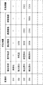
- FIG. 5 is a diagram showing an example of deterioration information in the first embodiment.
- the deterioration information includes detection status, maintenance status, detection result, confirmation result, repair result, and expiration date.
- a detection status is an item that indicates whether or not road deterioration is detected in a certain section.
- the detection status is set to "undetected” indicating that road deterioration has not been detected or “detected” indicating that road deterioration has been detected.
- the maintenance status is an item that indicates the status of maintenance for road deterioration in a certain section.
- the maintenance status includes "unconfirmed” indicating that road deterioration has not been confirmed locally (waiting for confirmation), “confirmed” indicating that road deterioration has been confirmed locally (waiting for repair), And “repaired” is set to indicate that the repair has been performed.
- the maintenance statuses "unconfirmed”, “confirmed”, and “repaired” are also referred to as the first status, the second status, and the third status, respectively.
- the detection result of the road deterioration described above is set as the detection result.
- Confirmation results and repair results are set with the confirmation results and repair results at the site by workers, etc., respectively.
- the confirmation result and the repair result are transmitted from, for example, the worker's portable terminal or the like (not shown).
- FIG. 6 is a diagram showing an example of road deterioration confirmation results in the first embodiment.
- the confirmation result includes confirmation date and time, confirmation position, confirmation image, and confirmation comment.
- the confirmation date/time, confirmation position, confirmation image, and confirmation comment are respectively the date/time and position when the road deterioration confirmation work was performed, the confirmed road deterioration image, and the confirmation worker's comment. .
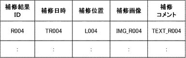
- FIG. 7 is a diagram showing an example of repair results for road deterioration in the first embodiment.
- the repair result includes repair date and time, repair position, repair image, and repair comment.
- the repair date, repair position, repair image, and repair comment are the date and position of repair work for road deterioration, the repaired road deterioration image, and the repair worker's comment, respectively. be.
- the expiration date of the deterioration information is set.
- a date and time after a predetermined confirmed valid period from the date and time when the maintenance status is updated to "confirmed” is set as the expiration date.
- a date and time after a predetermined repaired valid period from the date and time when the maintenance status is updated to "repaired” is set as the expiration date.
- the confirmed effective period and the repaired effective period are also referred to as the first effective period and the second effective period, respectively.
- the confirmed validity period and the repaired validity period are set in advance according to predetermined conditions (for example, repair history of the road in the section, traffic volume, material, etc.).
- the deterioration information update unit 24 sets the detection status of the section to "detected".
- the deterioration information update unit 24 updates the maintenance status of the deterioration information of the section according to the maintenance status of the road deterioration of the section. Further, the deterioration information update unit 24 initializes the deterioration information of the partition when the expiration date of the deterioration information of the partition has passed (sets the detection status to "undetected").
- the deterioration information includes detection status "detected”, maintenance status "repaired”, detection result, confirmation result, repair result, and An expiration date “E004” based on the repaired expiration date is set.
- the block information storage unit 25 stores, as block (mesh) information, for example, a block (mesh) obtained by dividing the ground surface of each region into a predetermined size based on the latitude and longitude lines, and a block ID that identifies each of the blocks. (IDentifier) (mesh code) is stored.
- IDentifier (mesh code)
- the size of the partition for example, a size that can be visually confirmed by a worker who performs maintenance on site is used.
- the divisions and division IDs standard regional meshes created by administrative agencies such as the country, divided regional meshes that are further subdivided from the standard regional meshes, or regional meshes that are further subdivided from the divided regional meshes are used. .
- the regional mesh for example, a mesh with a side length of about 15.6 m or a mesh shorter than that may be used.
- the deterioration information storage unit 26 stores deterioration information of each section.
- the deterioration information storage unit 26 stores the deterioration information of the partition in association with the partition ID of each partition as shown in FIG.
- the display control unit 27 acquires the deterioration information from the deterioration information storage unit 26 and causes the display device 30 to display the deterioration information for each section in a predetermined display mode, for example.
- the road deterioration detection process is a process of updating deterioration information for each section regarding road deterioration detected based on sensor information transmitted from each vehicle 40 .
- the road deterioration detection process will be described below using the sensor information in FIG. 3 and the deterioration information in FIG.
- FIG. 8 is a flowchart showing road deterioration detection processing in the first embodiment.
- the sensor information acquisition unit 21 of the road deterioration diagnosis device 20 acquires, for example, sensor information (date and time, position, image, and acceleration) transmitted from the vehicle 40 (step S11).
- the sensor information acquisition unit 21 acquires sensor information as shown in FIG.
- the sensor information acquisition unit 21 causes the sensor information storage unit 22 to store the acquired sensor information.
- the deterioration detection unit 23 acquires sensor information from the sensor information storage unit 22, and detects road deterioration at the position of the sensor information based on the acquired sensor information (step S12). When road deterioration is detected (step S ⁇ b>13 /Yes), the deterioration detector 23 outputs the detection result to the deterioration information updater 24 . For example, when a pothole is detected by the sensor information of date and time "TD002" in FIG.
- step S13/No If road deterioration is not detected (step S13/No), the process from step S11 is repeated.
- the deterioration information updating unit 24 acquires the section ID of the section in which road deterioration has been detected (step S14).
- the deterioration information updating unit 24 refers to the division information stored in the division information storage unit 25, determines the division including the detection position of road deterioration, and acquires the division ID of the division. For example, the deterioration information updating unit 24 acquires the section ID "002" of the section including the detection position "L002" of the detection result ID "D002".
- the deterioration information update unit 24 acquires the deterioration information of the section in which road deterioration is detected, stored in the deterioration information storage unit 26 (step S15).
- the deterioration information update unit 24 sets the deterioration information detection status to "detected” (step S17). Further, the deterioration information updating unit 24 sets "unconfirmed” to the maintenance status of the deterioration information (step S18). Further, the deterioration information updating unit 24 sets the detection result acquired from the deterioration detecting unit 23 to the deterioration information (step S19).
- the deterioration information of the section "002" is set as shown in FIG.
- the deterioration information update unit 24 notifies the user via the display device 30 or the like that the detection status of deterioration information has been set to "detected" (that road deterioration has been detected in the section). may be notified to
- step S11 After that, the process from step S11 is repeated.
- step S16 the process from step S11 is repeated without updating the deterioration information detection status or maintenance status.
- the maintenance status update process is a process of updating the maintenance status of the deterioration information according to the detected road deterioration maintenance status.
- the maintenance status update process is executed when the road deterioration diagnosis device 20 acquires the road deterioration confirmation result or repair result transmitted from the mobile terminal or the like of the worker.
- FIG. 9 is a flowchart showing maintenance status update processing in the first embodiment.
- the deterioration information updating unit 24 of the road deterioration diagnosis device 20 acquires the confirmation result or the repair result (step S21).
- the deterioration information updating unit 24 acquires the section ID of the section that has been confirmed or repaired based on the confirmation result or repair result (step S22).
- the deterioration information updating unit 24 refers to the block information stored in the block information storage unit 25, determines the block containing the confirmation position or the repair position, and acquires the block ID of the block.
- the deterioration information updating unit 24 may use the section ID.
- the deterioration information updating unit 24 updates the maintenance status of the deterioration information of the confirmed section to "confirmed" (step S24). Further, the deterioration information update unit 24 sets the confirmation result in the deterioration information (step S25). Further, the deterioration information update unit 24 sets the expiration date of the deterioration information to an expiration date based on the confirmed expiration date (step S26).
- the deterioration information updating unit 24 updates the maintenance status of the deterioration information of the section where the repair has been performed to "repaired" (step S27). Further, the deterioration information updating unit 24 sets the repair result to the deterioration information (step S28). Further, the deterioration information update unit 24 sets the expiration date of the deterioration information to an expiration date based on the repaired expiration date (step S29).
- the deterioration information of the section "004" is updated as shown in FIG.
- the expiration date processing is processing for initializing the deterioration information of each partition when the expiration date of the deterioration information of each partition has passed. Expiration processing is repeatedly executed for each predetermined period.
- FIG. 10 is a flowchart showing expiration date processing in the first embodiment.
- the deterioration information updating unit 24 selects one partition (step S31).
- the deterioration information update unit 24 acquires the deterioration information of the selected section from the deterioration information storage unit 26 (step S32).
- the deterioration information updating unit 24 initializes the deterioration information. That is, the deterioration information update unit 24 sets the detection status of the deterioration information to "undetected” and erases information other than the detection status (step S34). In this case, the deterioration information updating unit 24 notifies that the deterioration information detection status is set to "undetected” (that the expiration date of the maintenance status "confirmed” and "repaired” in the section has passed). The user may be notified via the display device 30 or the like.
- the deterioration information updating unit 24 may store the deterioration information before initialization in a storage unit (not shown). As a result, as will be described later, even after the expiration date has passed, it is possible to present to the user the expired maintenance status "confirmed” and "repaired” deterioration information.
- the deterioration information update unit 24 repeats the processing from step S31 for all the sections stored in the deterioration information storage unit 26 (step S35).
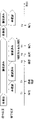
- FIG. 11 is a diagram showing an example of chronological changes in detection status and maintenance status in deterioration information of a certain section in the first embodiment.
- the deterioration information updating unit 24 changes the detection status to "detected".
- the maintenance status is set to "unconfirmed” (step S18).
- the deterioration information updating unit 24 updates the maintenance status to "confirmed" (step S24), and sets the expiration date based on the confirmed expiration period. Set (step S26).
- the deterioration information update unit 24 initializes the deterioration information (sets the detection status to "undetected") (step S34).
- the deterioration information updating unit 24 sets the detection status to "detected” (step S17), "unconfirmed” is set in the maintenance status (step S18).
- the detection status is set to "undetected", and when the pothole is detected again, the detection status is "detected” and the maintenance status is "unconfirmed”. is set. Therefore, even if the confirmed pothole is not repaired, the information about the pothole is managed again by the repeated driving of the vehicle 40, thereby preventing the pothole from being left unattended. be able to.
- FIG. 12 is a diagram showing another example of time-series changes in detection status and maintenance status in deterioration information of a certain section in the first embodiment.
- the deterioration information update unit 24 sets the detection status "detected” and the maintenance status "unconfirmed” at time T1 (steps S17 and S18), and sets the maintenance status "not confirmed” at time T2, as in FIG. Confirmed” is updated (step S24).
- the deterioration information update unit 24 updates the maintenance status to "repaired" (step S27), and sets the expiration date based on the repaired effective period. Set (step S29).
- the deterioration information update unit 24 initializes the deterioration information (sets the detection status to "undetected") (step S34).
- the deterioration information updating unit 24 sets the detection status "detected” and the maintenance status "unconfirmed” at time T8 (steps S17 and S18), as in FIG.
- pothole repair marks may be erroneously detected as potholes for a while after repair.
- the deterioration detection unit 23 may use a value that is stricter than usual as a detection threshold for deterioration detection by image during the repaired effective period.
- the road deterioration position display processing is processing for displaying deterioration information on a map.
- FIG. 13 is a flowchart showing road deterioration position display processing in the first embodiment.
- the display control unit 27 receives a map display request from the user of the road deterioration diagnosis device 20 (step S41).
- the display control unit 27 acquires the deterioration information of each section stored in the deterioration information storage unit 26 (step S42).
- the display control unit 27 displays the acquired deterioration information of each section on the map (step S43).
- the display control unit 27 displays the detection status and the maintenance status, for example, at the positions included in the detection result of the deterioration information of each section.
- FIG. 14 is a diagram showing a display example of deterioration information on a map in the first embodiment.
- the example in FIG. 14 corresponds to the deterioration information in FIG.
- the display control unit 27 displays an icon corresponding to the maintenance status at the position where the pothole is detected in each section with the detection status “detected”.
- the maintenance statuses "unconfirmed”, “confirmed”, and “repaired” are displayed in round icon colors of "black”, “gray”, and “white”, respectively.
- a radio button "including expired” for specifying the display of degradation information that has passed the expiration date and a field for specifying the range of the expiration date are displayed.
- the display control unit 27 specifies the expiration date among the deterioration information past the expiration date stored in a storage unit (not shown).
- the deterioration information within the specified range may also be displayed on the map. In this case, the display control unit 27 may display the deterioration information whose expiration date has passed in a manner different from other deterioration information.
- the display control unit 27 detects, in addition to the detection status and maintenance status of deterioration information corresponding to the section of the icon, detection results, confirmation results, and repair results. , expiration date, and other detailed information may be displayed.
- the date and time of detection the original image of detection, the date and time of confirmation, the confirmation image, the date and time of maintenance, and the repaired image may be displayed.
- FIG. 15 is a diagram showing a display example of detailed deterioration information in the first embodiment.
- the maintenance status “confirmed” icon of the section ID “003” is clicked or moused over, the detailed information of the deterioration information of the section is displayed.
- the case where potholes are detected as road deterioration and the detection status of potholes and the maintenance status for each section is managed as an example.
- other road deterioration cracks, rutting, etc.
- road deterioration based on indicators crack rate, rut amount, flatness, MCI, IRI, etc.
- the deterioration information storage unit 26 of the road deterioration diagnosis device 20 stores the detection status indicating whether or not road deterioration is detected in each section obtained by dividing a predetermined area into a predetermined size, and the detected state. This is because the deterioration information including the maintenance status of road deterioration is stored, and the display control unit 27 causes the display device 30 to display a map showing the deterioration information in each section.
- FIG. 16 is a block diagram showing the configuration of the road deterioration diagnostic device 1 in the second embodiment.
- the road deterioration diagnostic device 1 includes a storage section 2 and a display control section 3 .
- the storage unit 2 and the display control unit 3 are embodiments of storage means and display control means, respectively.
- the storage unit 2 stores, for each section obtained by dividing a predetermined area into a predetermined size, detection status indicating whether or not road deterioration is detected in the section, and deterioration information including the maintenance status of the detected road deterioration. do.
- the display control unit 3 causes the display means to display a map showing deterioration information in each section.
- the storage unit 2 includes, for each section obtained by dividing a predetermined area into a predetermined size, the detection status indicating whether or not road deterioration is detected in the section, and the maintenance status of the detected road deterioration. This is because the deterioration information is stored and the display control unit 3 causes the display means to display a map showing the deterioration information in each section.
- each component of the road deterioration diagnosis devices 1 and 20 represents a functional unit block.
- a part or all of each component of each device may be realized by any combination of the computer 500 and a program.
- This program may be recorded in a non-volatile recording medium.
- non-volatile recording media include CD-ROMs (Compact Disc Read Only Memory), DVDs (Digital Versatile Discs), SSDs (Solid State Drives), and the like.
- FIG. 17 is a block diagram showing an example of the hardware configuration of computer 500.
- computer 500 includes, for example, CPU (Central Processing Unit) 501, ROM (Read Only Memory) 502, RAM (Random Access Memory) 503, program 504, storage device 505, drive device 507, communication interface 508 , an input device 509 , an output device 510 , an input/output interface 511 and a bus 512 .
- CPU Central Processing Unit
- ROM Read Only Memory
- RAM Random Access Memory
- the program 504 includes instructions for realizing each function of each device.
- the program 504 is stored in advance in the ROM 502 , RAM 503 and storage device 505 .
- the CPU 501 implements each function of each device by executing instructions included in the program 504 .
- the CPU 501 of the road deterioration diagnosis device 20 executes the commands included in the program 504 to realize the functions of the sensor information acquisition unit 21, the deterioration detection unit 23, the deterioration information update unit 24, and the display control unit 27.
- the RAM 503 may store data processed in each function of each device.
- the RAM 503 of the road deterioration diagnosis device 20 stores the data (sensor information) of the sensor information storage unit 22, the data (division information) of the division information storage unit 25, the data (deterioration information) of the deterioration information storage unit 26, and the like.
- the drive device 507 reads from and writes to the recording medium 506 .
- Communication interface 508 provides an interface with a communication network.
- the input device 509 is, for example, a mouse, a keyboard, or the like, and receives input of information from an operator or the like.
- the output device 510 is, for example, a display, and outputs (displays) information to an operator or the like.
- the input/output interface 511 provides an interface with peripheral devices.
- a bus 512 connects each of these hardware components.
- the program 504 may be supplied to the CPU 501 via a communication network, or may be stored in the recording medium 506 in advance, read by the drive device 507 and supplied to the CPU 501 .
- FIG. 17 is an example, and components other than these may be added, and some components may not be included.
- each device may be implemented by any combination of a computer and a program that are different for each component.
- a plurality of components included in each device may be realized by any combination of a single computer and a program.
- each component of each device may be realized by a general-purpose or dedicated circuit including a processor or the like, or a combination thereof. These circuits may be composed of a single chip, or may be composed of multiple chips connected via a bus. A part or all of each component of each device may be realized by a combination of the above-described circuits and the like and programs.
- each component of each device when a part or all of each component of each device is realized by a plurality of computers, circuits, etc., the plurality of computers, circuits, etc. may be centrally arranged or distributed.
- Reference Signs List 1 20 road deterioration diagnosis device 2 storage unit 3, 27 display control unit 10 road deterioration diagnosis system 21 sensor information acquisition unit 22 sensor information storage unit 23 deterioration detection unit 24 deterioration information update unit 25 section information storage unit 26 deterioration information storage unit 500 computer 501 CPU 502 ROMs 503 RAM 504 program 505 storage device 506 recording medium 507 drive device 508 communication interface 509 input device 510 output device 511 input/output interface 512 bus
Landscapes
- Engineering & Computer Science (AREA)
- Physics & Mathematics (AREA)
- General Physics & Mathematics (AREA)
- Business, Economics & Management (AREA)
- Remote Sensing (AREA)
- Radar, Positioning & Navigation (AREA)
- Theoretical Computer Science (AREA)
- Human Resources & Organizations (AREA)
- Quality & Reliability (AREA)
- Operations Research (AREA)
- Marketing (AREA)
- Entrepreneurship & Innovation (AREA)
- Strategic Management (AREA)
- Tourism & Hospitality (AREA)
- General Business, Economics & Management (AREA)
- Economics (AREA)
- Multimedia (AREA)
- Automation & Control Theory (AREA)
- Computer Vision & Pattern Recognition (AREA)
- Traffic Control Systems (AREA)
- Navigation (AREA)
- Instructional Devices (AREA)
Priority Applications (4)
| Application Number | Priority Date | Filing Date | Title |
|---|---|---|---|
| US18/281,664 US20240152876A1 (en) | 2021-03-18 | 2021-03-18 | Road deterioration diagnosis device, road deterioration diagnosis method, and recording medium |
| JP2021518017A JP6906271B1 (ja) | 2021-03-18 | 2021-03-18 | 道路劣化診断装置、道路劣化診断方法、及び、プログラム |
| PCT/JP2021/011139 WO2022195812A1 (ja) | 2021-03-18 | 2021-03-18 | 道路劣化診断装置、道路劣化診断方法、及び、記録媒体 |
| JP2021104869A JP7600895B2 (ja) | 2021-03-18 | 2021-06-24 | 道路劣化診断装置、道路劣化診断方法、及び、プログラム |
Applications Claiming Priority (1)
| Application Number | Priority Date | Filing Date | Title |
|---|---|---|---|
| PCT/JP2021/011139 WO2022195812A1 (ja) | 2021-03-18 | 2021-03-18 | 道路劣化診断装置、道路劣化診断方法、及び、記録媒体 |
Publications (1)
| Publication Number | Publication Date |
|---|---|
| WO2022195812A1 true WO2022195812A1 (ja) | 2022-09-22 |
Family
ID=76918278
Family Applications (1)
| Application Number | Title | Priority Date | Filing Date |
|---|---|---|---|
| PCT/JP2021/011139 Ceased WO2022195812A1 (ja) | 2021-03-18 | 2021-03-18 | 道路劣化診断装置、道路劣化診断方法、及び、記録媒体 |
Country Status (3)
| Country | Link |
|---|---|
| US (1) | US20240152876A1 (https=) |
| JP (2) | JP6906271B1 (https=) |
| WO (1) | WO2022195812A1 (https=) |
Families Citing this family (4)
| Publication number | Priority date | Publication date | Assignee | Title |
|---|---|---|---|---|
| JP7639770B2 (ja) * | 2022-05-24 | 2025-03-05 | トヨタ自動車株式会社 | 情報処理装置、情報処理方法、及び、プログラム |
| US20250232667A1 (en) * | 2024-01-16 | 2025-07-17 | Honda Motor Co., Ltd. | Systems and methods for vehicle-centered community improvement |
| US20250292541A1 (en) * | 2024-03-14 | 2025-09-18 | King Fahd University Of Petroleum And Minerals | System and method to detect road anomalies |
| US20260100126A1 (en) * | 2024-10-03 | 2026-04-09 | Toyota Motor North America, Inc. | Determining an action to be performed for a predicted road issue |
Citations (4)
| Publication number | Priority date | Publication date | Assignee | Title |
|---|---|---|---|---|
| JP2019137989A (ja) * | 2018-02-06 | 2019-08-22 | 国立大学法人 東京大学 | 構造物変状検出装置 |
| JP2019196680A (ja) * | 2018-05-11 | 2019-11-14 | 西日本電信電話株式会社 | 舗装情報収集点検システム、舗装情報収集点検方法、及びプログラム |
| WO2020022042A1 (ja) * | 2018-07-25 | 2020-01-30 | 日本電気株式会社 | 劣化診断装置、劣化診断システム、劣化診断方法、プログラムを記憶する記憶媒体 |
| JP2021025242A (ja) * | 2019-08-01 | 2021-02-22 | アイシン・エィ・ダブリュ株式会社 | 優先度決定装置及びコンピュータプログラム |
-
2021
- 2021-03-18 WO PCT/JP2021/011139 patent/WO2022195812A1/ja not_active Ceased
- 2021-03-18 JP JP2021518017A patent/JP6906271B1/ja active Active
- 2021-03-18 US US18/281,664 patent/US20240152876A1/en active Pending
- 2021-06-24 JP JP2021104869A patent/JP7600895B2/ja active Active
Patent Citations (4)
| Publication number | Priority date | Publication date | Assignee | Title |
|---|---|---|---|---|
| JP2019137989A (ja) * | 2018-02-06 | 2019-08-22 | 国立大学法人 東京大学 | 構造物変状検出装置 |
| JP2019196680A (ja) * | 2018-05-11 | 2019-11-14 | 西日本電信電話株式会社 | 舗装情報収集点検システム、舗装情報収集点検方法、及びプログラム |
| WO2020022042A1 (ja) * | 2018-07-25 | 2020-01-30 | 日本電気株式会社 | 劣化診断装置、劣化診断システム、劣化診断方法、プログラムを記憶する記憶媒体 |
| JP2021025242A (ja) * | 2019-08-01 | 2021-02-22 | アイシン・エィ・ダブリュ株式会社 | 優先度決定装置及びコンピュータプログラム |
Also Published As
| Publication number | Publication date |
|---|---|
| JPWO2022195812A1 (https=) | 2022-09-22 |
| JP6906271B1 (ja) | 2021-07-21 |
| JP7600895B2 (ja) | 2024-12-17 |
| US20240152876A1 (en) | 2024-05-09 |
| JP2022145401A (ja) | 2022-10-04 |
Similar Documents
| Publication | Publication Date | Title |
|---|---|---|
| WO2022195812A1 (ja) | 道路劣化診断装置、道路劣化診断方法、及び、記録媒体 | |
| JP4305361B2 (ja) | 道路管理システム | |
| US11315428B2 (en) | Management of mobile objects | |
| CN105761490A (zh) | 对危化品运输车辆在服务区停靠的预警方法 | |
| JP7600872B2 (ja) | 情報処理装置、情報処理方法、及び、プログラム | |
| US20180148898A1 (en) | Road state management apparatus and method | |
| JP7293174B2 (ja) | 道路周辺物監視装置、道路周辺物監視プログラム | |
| US10168424B1 (en) | Management of mobile objects | |
| JP2021162868A (ja) | 劣化表示システム、劣化表示方法、及び、プログラム | |
| CN112700201A (zh) | 货源推荐方法、电子设备和存储介质 | |
| WO2017018031A1 (ja) | 走行データ抽出プログラム、走行データ抽出方法および走行データ抽出装置 | |
| JP7435747B2 (ja) | 巡回ルート作成装置、巡回ルート作成方法、及びプログラム | |
| CN111081063B (zh) | 创建观察数据、求取车道数量的方法及相关的系统、服务器单元和控制器 | |
| JP7586027B2 (ja) | 装置、方法、及び、プログラム | |
| CN113689705A (zh) | 车辆闯红灯检测方法、装置、计算机设备和存储介质 | |
| US11787437B2 (en) | Driving domain management unit, driving domain management system, and driving domain management method | |
| JP2017188164A (ja) | 画像取得装置、端末および画像取得システム | |
| JP6892197B1 (ja) | 劣化表示システム、劣化表示方法、及び、プログラム | |
| JP7334851B2 (ja) | 劣化診断装置、劣化診断システム、劣化診断方法、及び、プログラム | |
| US20240355151A1 (en) | Gathering and Distributing Metadata of a Surrounding of a Vehicle | |
| JP7750280B2 (ja) | インフラ診断装置、インフラ診断方法、及び、プログラム | |
| JP7764627B2 (ja) | 地図情報作成装置及び地図情報作成方法 | |
| CN110867073A (zh) | 交通信息处理方法及装置 | |
| WO2025203287A1 (ja) | 道路診断システム、道路診断方法および記録媒体 | |
| JP2018181130A (ja) | 走行実績収集評価システムおよび走行実績評価装置 |
Legal Events
| Date | Code | Title | Description |
|---|---|---|---|
| ENP | Entry into the national phase |
Ref document number: 2021518017 Country of ref document: JP Kind code of ref document: A |
|
| 121 | Ep: the epo has been informed by wipo that ep was designated in this application |
Ref document number: 21931561 Country of ref document: EP Kind code of ref document: A1 |
|
| WWE | Wipo information: entry into national phase |
Ref document number: 18281664 Country of ref document: US |
|
| NENP | Non-entry into the national phase |
Ref country code: DE |
|
| 122 | Ep: pct application non-entry in european phase |
Ref document number: 21931561 Country of ref document: EP Kind code of ref document: A1 |