(第1の実施形態)
第1の実施形態について説明する。
(First embodiment)
A first embodiment will be described.
(システム構成)
はじめに、第1の実施形態における、道路劣化診断システムの構成を説明する。図1は、第1の実施形態における、道路劣化診断システム10の構成を示すブロック図である。図1を参照すると、道路劣化診断システム10は、道路劣化診断装置20、表示装置30、移動体である、複数の車両40_1、40_2、…40_N(Nは自然数)(以下、まとめて、車両40とも記載)を含む。移動体は、自動二輪車や自転車、ドローン、自動運転機能の付いたロボットまたは車両、人(歩行者)でもよい。
(System configuration)
First, the configuration of the road deterioration diagnosis system in the first embodiment will be described. FIG. 1 is a block diagram showing the configuration of a road deterioration diagnosis system 10 according to the first embodiment. Referring to FIG. 1, the road deterioration diagnosis system 10 includes a road deterioration diagnosis device 20, a display device 30, and a plurality of vehicles 40_1, 40_2, . Also described). A mobile object may be a motorcycle, a bicycle, a drone, a robot or vehicle with an automatic driving function, or a person (pedestrian).
車両40は、搭載されたセンサが取得する所定のセンサ情報を取得する。センサ情報としては、画像や、加速度、取得日時、及び、位置等が含まれる。画像は、例えば、車両40に搭載されたドライブレコーダーのカメラ等の撮像装置により、道路を走行しながら、撮像(取得)される道路の路面の画像である。また、加速度は、道路を走行しながら、例えば、加速度センサにより、検出(取得)される道路の路面の凹凸を上下方向の振動として表されたものである。また、位置は、撮像装置による画像撮像時や、加速度センサによる加速度取得時に、GPS(Global Positioning System)等の位置検出センサにより取得される位置である。車両40は、画像、加速度、これらの情報の取得日時、及び、位置を含むセンサ情報を、道路劣化診断装置20へ送信する。例えば、位置としては、緯度及び経度を用いてもよい。また、本実施形態では、センサ情報に画像及び加速度の両方が含まれている場合について説明するが、それに限らず、画像及び加速度の少なくともどちらか一方が含まれていればよい。
The vehicle 40 acquires predetermined sensor information acquired by the mounted sensors. The sensor information includes an image, acceleration, date and time of acquisition, position, and the like. The image is, for example, an image of the road surface captured (obtained) by an imaging device such as a drive recorder camera mounted on the vehicle 40 while driving on the road. Further, the acceleration is expressed as vertical vibration of the unevenness of the road surface detected (acquired) by an acceleration sensor while traveling on the road. The position is a position acquired by a position detection sensor such as a GPS (Global Positioning System) when an image is captured by an imaging device or acceleration is acquired by an acceleration sensor. The vehicle 40 transmits sensor information including an image, acceleration, acquisition date and time of these information, and position to the road deterioration diagnosis device 20 . For example, latitude and longitude may be used as the position. Also, in the present embodiment, a case where both an image and an acceleration are included in the sensor information will be described.
道路劣化診断装置20は、車両40から送信されるセンサ情報に基づいて、道路劣化を検出する。ここで、道路劣化診断装置20は、各地域の地表面を区画に分割し、検出した道路劣化を各区画で管理する。道路劣化診断装置20は、区画ごとの劣化情報を表示装置30に表示させることにより、劣化情報を、道路劣化診断装置20のユーザへ提示する。ここで、ユーザとは、例えば、事業者の職員(管理者や作業者)である。
The road deterioration diagnosis device 20 detects road deterioration based on sensor information transmitted from the vehicle 40. Here, the road deterioration diagnosis device 20 divides the ground surface of each area into sections, and manages the detected road deterioration in each section. The road deterioration diagnosis device 20 presents the deterioration information to the user of the road deterioration diagnosis device 20 by causing the display device 30 to display the deterioration information for each section. Here, the user is, for example, an employee (manager or worker) of the business.
道路劣化診断装置20及び表示装置30は、例えば、事業者の設備管理施設に配置される。道路劣化診断装置20及び表示装置30は、一体でも別体でもよい。また、道路劣化診断装置20は、事業者の設備管理施設以外に配置されてもよい。この場合、道路劣化診断装置20は、クラウドコンピューティングシステムにより実現されてもよい。なお、表示装置30は、本開示の表示手段の一実施形態である。
The road deterioration diagnosis device 20 and the display device 30 are installed, for example, in the equipment management facility of the operator. The road deterioration diagnostic device 20 and the display device 30 may be integrated or separated. Moreover, the road deterioration diagnosis device 20 may be arranged outside the equipment management facility of the operator. In this case, the road deterioration diagnosis device 20 may be realized by a cloud computing system. Note that the display device 30 is an embodiment of the display means of the present disclosure.
センサ情報に基づく道路結果の検出方法には、画像解析や加速度を用いた公知技術が用いられる。画像解析を用いた道路劣化の検出としては、例えば、AI(Artificial Intelligence)を用いて道路劣化を解析する方法が挙げられる。また、加速度を用いた道路劣化の検出としては、例えば、路面に対して垂直方向の加速度を用いた路面の凹凸の程度を検出する方法が挙げられる。
Publicly known techniques using image analysis and acceleration are used for road result detection methods based on sensor information. Detection of road deterioration using image analysis includes, for example, a method of analyzing road deterioration using AI (Artificial Intelligence). Further, detection of road deterioration using acceleration includes, for example, a method of detecting the degree of unevenness of a road surface using acceleration in a direction perpendicular to the road surface.
図2は、第1の実施形態における、道路劣化診断装置20の構成の例を示すブロック図である。道路劣化診断装置20は、図2に示すように、センサ情報取得部21、センサ情報記憶部22、劣化検出部23、劣化情報更新部24、区画情報記憶部25、劣化情報記憶部26、及び、表示制御部27を含む。なお、区画情報記憶部25、劣化情報更新部24、及び、表示制御部27は、本開示の記憶手段、更新手段、及び、表示制御手段の一実施形態である。
FIG. 2 is a block diagram showing an example of the configuration of the road deterioration diagnosis device 20 in the first embodiment. As shown in FIG. 2, the road deterioration diagnosis device 20 includes a sensor information acquisition unit 21, a sensor information storage unit 22, a deterioration detection unit 23, a deterioration information update unit 24, a section information storage unit 25, a deterioration information storage unit 26, and , and a display control unit 27 . Note that the partition information storage unit 25, the deterioration information update unit 24, and the display control unit 27 are an embodiment of the storage means, update means, and display control means of the present disclosure.
センサ情報取得部21は、車両40からセンサ情報を取得する。センサ情報取得部21は、取得したセンサ情報をセンサ情報記憶部22に出力する。
The sensor information acquisition unit 21 acquires sensor information from the vehicle 40. The sensor information acquisition unit 21 outputs the acquired sensor information to the sensor information storage unit 22 .
センサ情報記憶部22は、センサ情報取得部21が出力したセンサ情報を記憶する。図3は、第1の実施形態における、センサ情報の例を示す図である。図3の例では、センサ情報は、日時、位置、画像、及び、加速度を含む。日時は、車両40が画像及び加速度を取得した日時を示す。位置は、画像及び加速度を取得した位置を示す。
The sensor information storage unit 22 stores the sensor information output by the sensor information acquisition unit 21. FIG. 3 is a diagram showing an example of sensor information in the first embodiment. In the example of FIG. 3, the sensor information includes date and time, position, image, and acceleration. The date and time indicates the date and time when the vehicle 40 acquired the image and the acceleration. Position indicates the position at which the image and acceleration are acquired.
劣化検出部23は、センサ情報に含まれる画像及び加速度の少なくとも一方に基づいて、道路劣化を検出する。ここで、劣化検出部23は、道路劣化として、例えば、ポットホールを検出する。ポットホールは、路面の舗装表面に生じた、例えば、直径0.1~1m程度の穴のことである。劣化検出部23は、これに限らず、道路劣化として、ひび割れや、わだち掘れ等を検出してもよい。また、劣化検出部23は、道路劣化を示す指標に基づき、道路劣化を検出してもよい。この場合、指標として、例えば、ひび割れ率や、わだち掘れ量、平坦性、MCI(Maintenance Control Index)、IRI(International Roughness Index)等が用いられる。劣化検出部23は、指標の値が所定の閾値を超えた場合、道路劣化として検出する。
The deterioration detection unit 23 detects road deterioration based on at least one of the image and acceleration included in the sensor information. Here, the deterioration detection unit 23 detects, for example, potholes as road deterioration. A pothole is, for example, a hole with a diameter of about 0.1 to 1 m that is formed on the pavement surface of a road surface. The deterioration detection unit 23 may detect cracks, ruts, and the like as road deterioration. Further, the deterioration detection unit 23 may detect road deterioration based on an index indicating road deterioration. In this case, for example, crack ratio, rutting amount, flatness, MCI (Maintenance Control Index), IRI (International Roughness Index), etc. are used as indexes. The deterioration detection unit 23 detects road deterioration when the value of the index exceeds a predetermined threshold.
以下、第1の実施形態では、劣化検出部23が道路劣化としてポットホールを検出する場合を例に説明する。
Hereinafter, in the first embodiment, a case where the deterioration detection unit 23 detects a pothole as road deterioration will be described as an example.
劣化検出部23は、検出した道路劣化についての検出結果を、劣化情報更新部24に出力する。
The deterioration detection unit 23 outputs the detection result of the detected road deterioration to the deterioration information update unit 24 .
図4は、第1の実施形態における、道路劣化の検出結果の例を示す図である。図4の例では、検出結果は、検出日時、検出位置、及び、検出元の画像を含む。ここで、検出日時、検出位置、及び、検出元の画像は、それぞれ、道路劣化(ポットホール)が検出されたセンサ情報に含まれる、日時、位置、及び、画像である。
FIG. 4 is a diagram showing an example of road deterioration detection results in the first embodiment. In the example of FIG. 4, the detection result includes the date and time of detection, the position of detection, and the image of the detection source. Here, the date and time of detection, the position of detection, and the image of the detection source are respectively the date and time, the position, and the image included in the sensor information in which the road deterioration (pothole) was detected.
劣化情報更新部24は、道路劣化が検出されたセンサ情報に含まれる位置と、区画情報記憶部25に記憶された区画(メッシュ)の情報に基づき、道路劣化が検出された区画を特定する。そして、劣化情報更新部24は、劣化検出部23から取得した道路劣化の検出結果に基づき、劣化情報記憶部26に記憶された各区画の劣化情報を設定、更新する。
The deterioration information update unit 24 identifies the block where road deterioration is detected based on the position included in the sensor information where road deterioration is detected and the block (mesh) information stored in the block information storage unit 25. Then, the deterioration information updating unit 24 sets and updates the deterioration information of each section stored in the deterioration information storage unit 26 based on the road deterioration detection result acquired from the deterioration detection unit 23 .
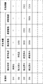
図5は、第1の実施形態における、劣化情報の例を示す図である。図5の例では、劣化情報は、検出状況、保守状況、検出結果、確認結果、補修結果、及び、有効期限を含む。
FIG. 5 is a diagram showing an example of deterioration information in the first embodiment. In the example of FIG. 5, the deterioration information includes detection status, maintenance status, detection result, confirmation result, repair result, and expiration date.
検出状況とは、ある区画における、道路劣化が検出されているか否かを示す項目である。検出状況には、道路劣化が検出されていないことを示す「未検出」か、検出されていることを示す「検出済み」が設定される。
A detection status is an item that indicates whether or not road deterioration is detected in a certain section. The detection status is set to "undetected" indicating that road deterioration has not been detected or "detected" indicating that road deterioration has been detected.
保守状況とは、ある区画における、道路劣化に対する保守の状況を示す項目である。保守状況には、道路劣化の現地での確認がされていない(確認待ちである)ことを示す「未確認」、現地での確認がされた(補修待ちである)ことを示す「確認済み」、及び、補修が行われたことを示す「補修済み」が設定される。以下、保守状況「未確認」、「確認済み」、及び、「補修済み」を、それぞれ、第1の状況、第2の状況、及び、第3の状況とも記載する。
The maintenance status is an item that indicates the status of maintenance for road deterioration in a certain section. The maintenance status includes "unconfirmed" indicating that road deterioration has not been confirmed locally (waiting for confirmation), "confirmed" indicating that road deterioration has been confirmed locally (waiting for repair), And "repaired" is set to indicate that the repair has been performed. Hereinafter, the maintenance statuses "unconfirmed", "confirmed", and "repaired" are also referred to as the first status, the second status, and the third status, respectively.
検出結果には、上述の道路劣化の検出結果が設定される。
The detection result of the road deterioration described above is set as the detection result.
確認結果、及び、補修結果には、それぞれ、作業者等による現地での確認結果、及び、補修結果が設定される。確認結果、及び、補修結果は、例えば、図示しない、作業者の携帯端末等から送信される。
Confirmation results and repair results are set with the confirmation results and repair results at the site by workers, etc., respectively. The confirmation result and the repair result are transmitted from, for example, the worker's portable terminal or the like (not shown).
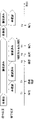
図6は、第1の実施形態における、道路劣化の確認結果の例を示す図である。図6の例では、確認結果は、確認日時、確認位置、確認画像、及び、確認コメントを含む。ここで、確認日時、確認位置、確認画像、及び、確認コメントは、それぞれ、道路劣化の確認作業が行われた日時、位置、確認した道路劣化の画像、及び、確認した作業者のコメントである。
FIG. 6 is a diagram showing an example of road deterioration confirmation results in the first embodiment. In the example of FIG. 6, the confirmation result includes confirmation date and time, confirmation position, confirmation image, and confirmation comment. Here, the confirmation date/time, confirmation position, confirmation image, and confirmation comment are respectively the date/time and position when the road deterioration confirmation work was performed, the confirmed road deterioration image, and the confirmation worker's comment. .
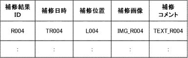
図7は、第1の実施形態における、道路劣化の補修結果の例を示す図である。図7の例では、補修結果は、補修日時、補修位置、補修画像、及び、補修コメントを含む。ここで、補修日時、補修位置、補修画像、及び、補修コメントは、それぞれ、道路劣化の補修作業が行われた日時、位置、補修済みの道路劣化の画像、及び、補修した作業者のコメントである。
FIG. 7 is a diagram showing an example of repair results for road deterioration in the first embodiment. In the example of FIG. 7, the repair result includes repair date and time, repair position, repair image, and repair comment. Here, the repair date, repair position, repair image, and repair comment are the date and position of repair work for road deterioration, the repaired road deterioration image, and the repair worker's comment, respectively. be.
有効期限には、劣化情報の有効期限が設定される。ここで、保守状況が「確認済み」の劣化情報には、有効期限として、保守状況が「確認済み」に更新された日時から、所定の確認済み有効期間後の日時が設定される。また、保守状況が「補修済み」の劣化情報には、有効期限として、保守状況が「補修済み」に更新された日時から、所定の補修済み有効期間後の日時が設定される。以下、これら、確認済み有効期間、補修済み有効期間を、それぞれ、第1の有効期間、第2の有効期間とも記載する。確認済み有効期間、補修済み有効期間は、所定の条件(例えば、区画の道路の補修履歴、交通量、材質等)に応じて、予め設定される。
In the expiration date, the expiration date of the deterioration information is set. Here, for deterioration information whose maintenance status is "confirmed", a date and time after a predetermined confirmed valid period from the date and time when the maintenance status is updated to "confirmed" is set as the expiration date. For deterioration information whose maintenance status is "repaired", a date and time after a predetermined repaired valid period from the date and time when the maintenance status is updated to "repaired" is set as the expiration date. Hereinafter, the confirmed effective period and the repaired effective period are also referred to as the first effective period and the second effective period, respectively. The confirmed validity period and the repaired validity period are set in advance according to predetermined conditions (for example, repair history of the road in the section, traffic volume, material, etc.).
劣化情報更新部24は、検出状況が「未検出」の区画で道路劣化が検出された場合に、該区画の検出状況に「検出済み」を設定する。
When road deterioration is detected in a section whose detection status is "undetected", the deterioration information update unit 24 sets the detection status of the section to "detected".
劣化情報更新部24は、区画の道路劣化の保守の状況に応じて、該区画の劣化情報の保守状況を更新する。また、劣化情報更新部24は、区画の劣化情報の有効期限が過ぎた場合に、該区画の劣化情報を初期化する(検出状況に「未検出」を設定する)。
The deterioration information update unit 24 updates the maintenance status of the deterioration information of the section according to the maintenance status of the road deterioration of the section. Further, the deterioration information update unit 24 initializes the deterioration information of the partition when the expiration date of the deterioration information of the partition has passed (sets the detection status to "undetected").
図5の例において、区画ID「001」では、ポットホールが検出されておらず、劣化情報には検出状況「未検出」が設定されている。区画ID「002」では、ポットホールが検出され、現地での確認が行われていないため、劣化情報には検出状況「検出済み」、保守状況「未確認」、及び、検出結果が設定されている。区画ID「003」では、ポットホールが検出され、現地での確認が行われているため、劣化情報には検出状況「検出済み」、保守状況「確認済み」、検出結果、確認結果、及び、確認済み有効期間に基づく有効期限「E003」が設定されている。区画ID「004」では、ポットホールが検出され、補修が行われているため、劣化情報には検出状況「検出済み」、保守状況「補修済み」、検出結果、確認結果、補修結果、及び、補修済み有効期間に基づく有効期限「E004」が設定されている。
In the example of FIG. 5, no potholes have been detected in the section ID "001", and the detection status "undetected" is set in the deterioration information. In the section ID "002", a pothole was detected and it was not confirmed on site, so the deterioration information is set with the detection status "detected", the maintenance status "unconfirmed", and the detection result. . Since a pothole was detected in the section ID "003" and was confirmed on-site, the deterioration information includes detection status "detected", maintenance status "confirmed", detection result, confirmation result, and An expiration date "E003" based on the confirmed expiration period is set. Since a pothole is detected and repaired in the section ID "004", the deterioration information includes detection status "detected", maintenance status "repaired", detection result, confirmation result, repair result, and An expiration date “E004” based on the repaired expiration date is set.
区画情報記憶部25は、区画(メッシュ)の情報として、例えば、緯線及び経線に基づき各地域の地表面を所定の大きさで区切った区画(メッシュ)と、当該区画の各々を識別する区画ID(IDentifier)(メッシュコード)と、を記憶する。区画の大きさとしては、例えば、現地で保守を行う作業者が目視で確認できる程度の大きさが用いられる。例えば、区画及び区画IDとしては、国等の行政機関が作成している標準地域メッシュ、標準地域メッシュを更に細分化した分割地域メッシュ、または、分割地域メッシュを更に細分化した地域メッシュが用いられる。地域メッシュとして、例えば、一辺の長さが約15.6mのメッシュや、それよりも短いメッシュを用いてもよい。
The block information storage unit 25 stores, as block (mesh) information, for example, a block (mesh) obtained by dividing the ground surface of each region into a predetermined size based on the latitude and longitude lines, and a block ID that identifies each of the blocks. (IDentifier) (mesh code) is stored. As the size of the partition, for example, a size that can be visually confirmed by a worker who performs maintenance on site is used. For example, as the divisions and division IDs, standard regional meshes created by administrative agencies such as the country, divided regional meshes that are further subdivided from the standard regional meshes, or regional meshes that are further subdivided from the divided regional meshes are used. . As the regional mesh, for example, a mesh with a side length of about 15.6 m or a mesh shorter than that may be used.
劣化情報記憶部26は、各区画の劣化情報を記憶する。劣化情報記憶部26は、図5のように、各区画の区画IDに関連づけて、当該区画の劣化情報を記憶する。
The deterioration information storage unit 26 stores deterioration information of each section. The deterioration information storage unit 26 stores the deterioration information of the partition in association with the partition ID of each partition as shown in FIG.
表示制御部27は、劣化情報記憶部26から劣化情報を取得し、区画ごとに劣化情報を所定の表示態様で、例えば、表示装置30に表示させる。
The display control unit 27 acquires the deterioration information from the deterioration information storage unit 26 and causes the display device 30 to display the deterioration information for each section in a predetermined display mode, for example.
次に、第1の実施形態の動作について説明する。
Next, the operation of the first embodiment will be described.
(道路劣化検出処理)
道路劣化検出処理について説明する。道路劣化検出処理は、各車両40から送信されるセンサ情報に基づき検出した道路劣化について、区画ごとに、劣化情報を更新する処理である。以下、図3のセンサ情報と、図5の劣化情報と、を用いて、道路劣化検出処理について説明する。
(Road deterioration detection process)
Road deterioration detection processing will be described. The road deterioration detection process is a process of updating deterioration information for each section regarding road deterioration detected based on sensor information transmitted from each vehicle 40 . The road deterioration detection process will be described below using the sensor information in FIG. 3 and the deterioration information in FIG.
図8は、第1の実施形態における、道路劣化検出処理を示すフローチャートである。道路劣化診断装置20のセンサ情報取得部21は、例えば、車両40から送信されるセンサ情報(日時、位置、画像、及び、加速度)を取得する(ステップS11)。例えば、センサ情報取得部21は、図3のようなセンサ情報を取得する。センサ情報取得部21は、取得したセンサ情報を、センサ情報記憶部22に記憶させる。
FIG. 8 is a flowchart showing road deterioration detection processing in the first embodiment. The sensor information acquisition unit 21 of the road deterioration diagnosis device 20 acquires, for example, sensor information (date and time, position, image, and acceleration) transmitted from the vehicle 40 (step S11). For example, the sensor information acquisition unit 21 acquires sensor information as shown in FIG. The sensor information acquisition unit 21 causes the sensor information storage unit 22 to store the acquired sensor information.
劣化検出部23は、センサ情報をセンサ情報記憶部22から取得し、取得したセンサ情報に基づいて、当該センサ情報の位置における道路劣化を検出する(ステップS12)。道路劣化が検出された場合(ステップS13/Yes)、劣化検出部23は、検出結果を劣化情報更新部24に出力する。例えば、図3の日時「TD002」のセンサ情報によりポットホールが検出された場合、劣化検出部23は、図4の検出結果「D002」を劣化情報更新部24に出力する。
The deterioration detection unit 23 acquires sensor information from the sensor information storage unit 22, and detects road deterioration at the position of the sensor information based on the acquired sensor information (step S12). When road deterioration is detected (step S<b>13 /Yes), the deterioration detector 23 outputs the detection result to the deterioration information updater 24 . For example, when a pothole is detected by the sensor information of date and time "TD002" in FIG.
道路劣化が検出されなかった場合(ステップS13/No)、ステップS11からの処理が繰り返される。
If road deterioration is not detected (step S13/No), the process from step S11 is repeated.
劣化情報更新部24は、検出結果に基づき、道路劣化を検出した区画の区画IDを取得する(ステップS14)。ここで、劣化情報更新部24は、区画情報記憶部25に記憶されている区画情報を参照して、道路劣化の検出位置が含まれる区画を判定して、当該区画の区画IDを取得する。例えば、劣化情報更新部24は、検出結果ID「D002」の検出位置「L002」が含まれる区画の区画ID「002」を取得する。
Based on the detection result, the deterioration information updating unit 24 acquires the section ID of the section in which road deterioration has been detected (step S14). Here, the deterioration information updating unit 24 refers to the division information stored in the division information storage unit 25, determines the division including the detection position of road deterioration, and acquires the division ID of the division. For example, the deterioration information updating unit 24 acquires the section ID "002" of the section including the detection position "L002" of the detection result ID "D002".
劣化情報更新部24は、劣化情報記憶部26に記憶されている、道路劣化を検出した区画の劣化情報を取得する(ステップS15)。
The deterioration information update unit 24 acquires the deterioration information of the section in which road deterioration is detected, stored in the deterioration information storage unit 26 (step S15).
取得した劣化情報の検出状況が「未検出」の場合(ステップS16/未検出)、劣化情報更新部24は、劣化情報の検出状況に「検出済み」を設定する(ステップS17)。また、劣化情報更新部24は、劣化情報の保守状況に「未確認」を設定する(ステップS18)。さらに、劣化情報更新部24は、劣化情報に、劣化検出部23から取得した検出結果を設定する(ステップS19)。
If the acquired deterioration information detection status is "undetected" (step S16/undetected), the deterioration information update unit 24 sets the deterioration information detection status to "detected" (step S17). Further, the deterioration information updating unit 24 sets "unconfirmed" to the maintenance status of the deterioration information (step S18). Further, the deterioration information updating unit 24 sets the detection result acquired from the deterioration detecting unit 23 to the deterioration information (step S19).
例えば、区画「002」の検出状況が「未検出」のときに検出結果「D002」が得られた場合、区画「002」の劣化情報は図5のように設定される。
For example, if the detection result "D002" is obtained when the detection status of the section "002" is "undetected", the deterioration information of the section "002" is set as shown in FIG.
なお、この場合、劣化情報更新部24は、劣化情報の検出状況に「検出済み」に設定されたこと(区画内で道路劣化が検出されたこと)を、表示装置30等を介して、ユーザに通知してもよい。
In this case, the deterioration information update unit 24 notifies the user via the display device 30 or the like that the detection status of deterioration information has been set to "detected" (that road deterioration has been detected in the section). may be notified to
以降、ステップS11からの処理が繰り返される。
After that, the process from step S11 is repeated.
また、取得した劣化情報の検出状況が「検出済み」の場合(ステップS16/検出済み)、劣化情報の検出状況や保守状況を更新することなく、ステップS11からの処理が繰り返される。
Also, if the acquired deterioration information detection status is "detected" (step S16/detected), the process from step S11 is repeated without updating the deterioration information detection status or maintenance status.
(保守状況更新処理)
保守状況更新処理について説明する。保守状況更新処理は、検出された道路劣化の保守の状況に応じて、劣化情報の保守状況を更新する処理である。保守状況更新処理は、道路劣化診断装置20が、作業者の携帯端末等から送信された、道路劣化の確認結果または補修結果を取得した場合に実行される。
(Maintenance status update process)
Maintenance status update processing will be described. The maintenance status update process is a process of updating the maintenance status of the deterioration information according to the detected road deterioration maintenance status. The maintenance status update process is executed when the road deterioration diagnosis device 20 acquires the road deterioration confirmation result or repair result transmitted from the mobile terminal or the like of the worker.
図9は、第1の実施形態における、保守状況更新処理を示すフローチャートである。道路劣化診断装置20の劣化情報更新部24は、確認結果または補修結果を取得する(ステップS21)。
FIG. 9 is a flowchart showing maintenance status update processing in the first embodiment. The deterioration information updating unit 24 of the road deterioration diagnosis device 20 acquires the confirmation result or the repair result (step S21).
劣化情報更新部24は、確認結果または補修結果に基づき、確認または補修が行われた区画の区画IDを取得する(ステップS22)。ここで、劣化情報更新部24は、区画情報記憶部25に記憶されている区画情報を参照して、確認位置または補修位置が含まれる区画を判定して、当該区画の区画IDを取得する。なお、取得した確認結果または補修結果が、確認または補修が行われた区画の区画IDを含む場合、劣化情報更新部24は、該区画IDを用いてもよい。
The deterioration information updating unit 24 acquires the section ID of the section that has been confirmed or repaired based on the confirmation result or repair result (step S22). Here, the deterioration information updating unit 24 refers to the block information stored in the block information storage unit 25, determines the block containing the confirmation position or the repair position, and acquires the block ID of the block. In addition, when the obtained confirmation result or repair result includes the section ID of the section in which the confirmation or repair was performed, the deterioration information updating unit 24 may use the section ID.
確認結果を取得した場合(ステップS23/確認結果)、劣化情報更新部24は、確認が行われた区画の劣化情報の保守状況を「確認済み」で更新する(ステップS24)。また、劣化情報更新部24は、劣化情報に、確認結果を設定する(ステップS25)。さらに、劣化情報更新部24は、劣化情報の有効期限に、確認済み有効期間に基づく有効期限を設定する(ステップS26)。
When the confirmation result is acquired (step S23/confirmation result), the deterioration information updating unit 24 updates the maintenance status of the deterioration information of the confirmed section to "confirmed" (step S24). Further, the deterioration information update unit 24 sets the confirmation result in the deterioration information (step S25). Further, the deterioration information update unit 24 sets the expiration date of the deterioration information to an expiration date based on the confirmed expiration date (step S26).
例えば、区画「003」の保守状況が「未確認」のときに、該区画の確認結果が得られた場合、区画「003」の劣化情報は、図5のように更新される。
For example, when the maintenance status of section "003" is "unconfirmed" and the confirmation result of the section is obtained, the deterioration information of section "003" is updated as shown in FIG.
補修結果を取得した場合(ステップS23/補修結果)、劣化情報更新部24は、補修が行われた区画の劣化情報の保守状況を「補修済み」で更新する(ステップS27)。また、劣化情報更新部24は、劣化情報に、補修結果を設定する(ステップS28)。さらに、劣化情報更新部24は、劣化情報の有効期限に、補修済み有効期間に基づく有効期限を設定する(ステップS29)。
When the repair result is obtained (step S23/repair result), the deterioration information updating unit 24 updates the maintenance status of the deterioration information of the section where the repair has been performed to "repaired" (step S27). Further, the deterioration information updating unit 24 sets the repair result to the deterioration information (step S28). Further, the deterioration information update unit 24 sets the expiration date of the deterioration information to an expiration date based on the repaired expiration date (step S29).
例えば、区画「004」の保守状況が「確認済み」のときに、該区画の補修結果が得られた場合、区画「004」の劣化情報は、図5のように更新される。
For example, when the maintenance status of the section "004" is "confirmed", and the repair result of the section is obtained, the deterioration information of the section "004" is updated as shown in FIG.
(有効期限処理)
有効期限処理について説明する。有効期限処理は、各区画の劣化情報の有効期限を過ぎた場合に、該区画の劣化情報を初期化するための処理である。有効期限処理は、所定の期間ごとに繰り返し実行される。
(expiration date processing)
Expiration processing will be explained. The expiration date processing is processing for initializing the deterioration information of each partition when the expiration date of the deterioration information of each partition has passed. Expiration processing is repeatedly executed for each predetermined period.
図10は、第1の実施形態における、有効期限処理を示すフローチャートである。
FIG. 10 is a flowchart showing expiration date processing in the first embodiment.
劣化情報更新部24は、区画を一つ選択する(ステップS31)。
The deterioration information updating unit 24 selects one partition (step S31).
劣化情報更新部24は、劣化情報記憶部26から、選択した区画の劣化情報を取得する(ステップS32)。
The deterioration information update unit 24 acquires the deterioration information of the selected section from the deterioration information storage unit 26 (step S32).
現在時刻が、選択した区画の劣化情報における有効期限を過ぎている場合(ステップS33/Yes)、劣化情報更新部24は、該劣化情報を初期化する。すなわち、劣化情報更新部24は、該劣化情報の検出状況に「未検出」を設定し、検出状況以外の情報を消去する(ステップS34)。この場合、劣化情報更新部24は、劣化情報の検出状況に「未検出」が設定されたこと(区画内の保守状況「確認済み」、「補修済み」の有効期限をこえたこと)を、表示装置30等を介して、ユーザに通知してもよい。
If the current time has passed the expiration date of the deterioration information of the selected section (step S33/Yes), the deterioration information updating unit 24 initializes the deterioration information. That is, the deterioration information update unit 24 sets the detection status of the deterioration information to "undetected" and erases information other than the detection status (step S34). In this case, the deterioration information updating unit 24 notifies that the deterioration information detection status is set to "undetected" (that the expiration date of the maintenance status "confirmed" and "repaired" in the section has passed). The user may be notified via the display device 30 or the like.
また、劣化情報更新部24は、初期化前の劣化情報を、図示しない記憶部に記憶させてもよい。これにより、後述するように、有効期限を過ぎた後でも、有効期限を過ぎた、保守状況「確認済み」、「補修済み」の劣化情報を、ユーザに提示できる。
Further, the deterioration information updating unit 24 may store the deterioration information before initialization in a storage unit (not shown). As a result, as will be described later, even after the expiration date has passed, it is possible to present to the user the expired maintenance status "confirmed" and "repaired" deterioration information.
劣化情報更新部24は、劣化情報記憶部26に記憶されている全ての区画について、ステップS31からの処理を繰り返す(ステップS35)。
The deterioration information update unit 24 repeats the processing from step S31 for all the sections stored in the deterioration information storage unit 26 (step S35).
(劣化情報更新の具体例)
ここで、上述の道路劣化検出処理、保守状況更新処理、及び、有効期限処理に伴う、劣化情報更新の具体例を説明する。
(Specific example of deterioration information update)
Here, a specific example of deterioration information update associated with the road deterioration detection process, maintenance status update process, and expiration date process described above will be described.
図11は、第1の実施形態における、ある区画の劣化情報における検出状況、及び、保守状況の時系列変化の例を示す図である。
FIG. 11 is a diagram showing an example of chronological changes in detection status and maintenance status in deterioration information of a certain section in the first embodiment.
図11に示すように、時刻T1に車両40が該区画を走行したセンサ情報に基づき、該区画内でポットホールが検出された場合、劣化情報更新部24は、検出状況に「検出済み」を設定するともに(ステップS17)、保守状況に「未確認」を設定する(ステップS18)。
As shown in FIG. 11, when a pothole is detected in the section based on the sensor information that the vehicle 40 has traveled in the section at time T1, the deterioration information updating unit 24 changes the detection status to "detected". In addition to setting (step S17), the maintenance status is set to "unconfirmed" (step S18).
次いで、時刻T2に、作業者により現地でポットホールが確認された場合、劣化情報更新部24は、保守状況を「確認済み」で更新し(ステップS24)、確認済み有効期間に基づく有効期限を設定する(ステップS26)。
Next, at time T2, when the worker confirms the pothole at the site, the deterioration information updating unit 24 updates the maintenance status to "confirmed" (step S24), and sets the expiration date based on the confirmed expiration period. Set (step S26).
その後、有効期限を過ぎる前の時刻T3、T4のセンサ情報に基づき、該区画内の時刻T1と同じ位置や異なる位置でポットホールが検出されても、検出状況「検出済み」、保守状況「確認済み」が維持される。
After that, based on the sensor information at times T3 and T4 before the expiration date, even if a pothole is detected at the same position as at time T1 in the section or at a different position, the detection status "detected" and the maintenance status "confirmed" "Done" is maintained.
次いで、有効期限を過ぎると、劣化情報更新部24は、劣化情報を初期化(検出状況に「未検出」を設定)する(ステップS34)。
Next, when the expiration date has passed, the deterioration information update unit 24 initializes the deterioration information (sets the detection status to "undetected") (step S34).
さらに、時刻T8に車両40が該区画を走行したセンサ情報に基づき、該区画内でポットホールが検出された場合、劣化情報更新部24は、検出状況に「検出済み」を設定するともに(ステップS17)、保守状況に「未確認」を設定する(ステップS18)。
Further, when a pothole is detected in the section based on the sensor information that the vehicle 40 has traveled in the section at time T8, the deterioration information updating unit 24 sets the detection status to "detected" (step S17), "unconfirmed" is set in the maintenance status (step S18).
本実施形態では、このように、劣化情報の保守状況に「確認済み」が設定されている場合は、ポットホールが検出されても、検出状況「検出済み」、保守状況「確認済み」が維持される。そのため、車両40が繰り返し走行した場合に検出される、確認済みのポットホールや、そのポットホールの補修時に確認、補修可能な他のポットホールについての情報を不必要に管理する事態を防ぐことができる。
In this embodiment, when "confirmed" is set in the maintenance status of the deterioration information, even if a pothole is detected, the detection status "detected" and the maintenance status "confirmed" are maintained. be done. Therefore, it is possible to prevent unnecessary management of information about confirmed potholes detected when the vehicle 40 repeatedly travels and other potholes that can be confirmed and repaired when the potholes are repaired. can.
また、本実施形態では、このように、有効期限を過ぎると、検出状況に「未検出」が設定され、再度ポットホールが検出された時点で、検出状況「検出済み」、保守状況「未確認」が設定される。そのため、確認済みのポットホールの補修がされなかったとしても、車両40が繰り返し走行することにより、そのポットホールについての情報は再び管理されることになるため、ポットホールが放置される事態を防ぐことができる。
In addition, in this embodiment, when the expiration date has passed, the detection status is set to "undetected", and when the pothole is detected again, the detection status is "detected" and the maintenance status is "unconfirmed". is set. Therefore, even if the confirmed pothole is not repaired, the information about the pothole is managed again by the repeated driving of the vehicle 40, thereby preventing the pothole from being left unattended. be able to.
図12は、第1の実施形態における、ある区画の劣化情報における検出状況、及び、保守状況の時系列変化の他の例を示す図である。
FIG. 12 is a diagram showing another example of time-series changes in detection status and maintenance status in deterioration information of a certain section in the first embodiment.
図12において、劣化情報更新部24は、図11と同様に、時刻T1に検出状況「検出済み」、保守状況「未確認」を設定し(ステップS17、S18)、時刻T2に、保守状況を「確認済み」で更新する(ステップS24)。
12, the deterioration information update unit 24 sets the detection status "detected" and the maintenance status "unconfirmed" at time T1 (steps S17 and S18), and sets the maintenance status "not confirmed" at time T2, as in FIG. Confirmed" is updated (step S24).
次いで、時刻T5に、作業者により現地でポットホールが補修された場合、劣化情報更新部24は、保守状況を「補修済み」で更新し(ステップS27)、補修済み有効期間に基づく有効期限を設定する(ステップS29)。
Next, at time T5, when the worker repairs the pothole at the site, the deterioration information update unit 24 updates the maintenance status to "repaired" (step S27), and sets the expiration date based on the repaired effective period. Set (step S29).
その後、有効期限を過ぎる前の時刻T6、T7のセンサ情報に基づき、該区画内の時刻T1と同じ位置や異なる位置でポットホールが検出されても、検出状況「検出済み」、保守状況「補修済み」が維持される。
After that, based on the sensor information at times T6 and T7 before the expiration date, even if a pothole is detected at the same position as at time T1 in the section or at a different position, the detection status is "detected" and the maintenance status is "repaired." "Done" is maintained.
次いで、有効期限を過ぎると、劣化情報更新部24は、劣化情報を初期化(検出状況に「未検出」を設定)する(ステップS34)。
Next, when the expiration date has passed, the deterioration information update unit 24 initializes the deterioration information (sets the detection status to "undetected") (step S34).
さらに、劣化情報更新部24は、図11と同様に、時刻T8に検出状況「検出済み」、保守状況「未確認」を設定する(ステップS17、S18)。
Further, the deterioration information updating unit 24 sets the detection status "detected" and the maintenance status "unconfirmed" at time T8 (steps S17 and S18), as in FIG.
一般に、画像による劣化検出では、ポットホールの補修跡は、補修後しばらくの間、ポットホールとして誤検出される可能性がある。
In general, in degradation detection using images, pothole repair marks may be erroneously detected as potholes for a while after repair.
本実施形態では、このように、劣化情報の保守状況に「補修済み」が設定されている場合は、ポットホールが検出されても、検出状況「検出済み」、保守状況「補修済み」が維持される。そのため、補修跡がある箇所を車両40が繰り返し走行した場合に、ポットホールの補修跡が、ポットホールとして誤検出されことにより、不必要な情報が提供される事態を防ぐことができる。
In this embodiment, when the maintenance status of the deterioration information is set to "repaired", even if a pothole is detected, the detection status "detected" and the maintenance status "repaired" are maintained. be done. Therefore, when the vehicle 40 repeatedly travels through a place where there is a repair mark, it is possible to prevent unnecessary information from being provided due to erroneous detection of the repair mark of the pothole as a pothole.
なお、このような、ポットホールの誤検出をより低減するために、劣化検出部23は、補修済み有効期間の間、画像による劣化検出の検出閾値として、通常より厳しい値を用いてもよい。
In order to further reduce such erroneous detection of potholes, the deterioration detection unit 23 may use a value that is stricter than usual as a detection threshold for deterioration detection by image during the repaired effective period.
(道路劣化位置表示処理)
道路劣化位置表示処理について説明する。道路劣化位置表示処理は、劣化情報を地図上に表示する処理である。
(Road deterioration position display processing)
The road deterioration position display processing will be described. The road deterioration position display processing is processing for displaying deterioration information on a map.
図13は、第1の実施形態における、道路劣化位置表示処理を示すフローチャートである。表示制御部27は、道路劣化診断装置20のユーザから、地図表示要求を受け付ける(ステップS41)。
FIG. 13 is a flowchart showing road deterioration position display processing in the first embodiment. The display control unit 27 receives a map display request from the user of the road deterioration diagnosis device 20 (step S41).
表示制御部27は、劣化情報記憶部26に記憶されている各区画の劣化情報を取得する(ステップS42)。
The display control unit 27 acquires the deterioration information of each section stored in the deterioration information storage unit 26 (step S42).
表示制御部27は、取得した各区画の劣化情報を、地図上に表示する(ステップS43)。ここで、表示制御部27は、例えば、各区画の劣化情報の検出結果に含まれる位置に、検出状況、及び、保守状況を表示する。
The display control unit 27 displays the acquired deterioration information of each section on the map (step S43). Here, the display control unit 27 displays the detection status and the maintenance status, for example, at the positions included in the detection result of the deterioration information of each section.
図14は、第1の実施形態における、地図上への劣化情報の表示例を示す図である。図14の例は、図5の劣化情報に対応する。表示制御部27は、例えば、図14のように、検出状況「検出済み」の各区画における、ポットホールが検出された位置に、保守状況に応じたアイコンを表示させる。図14の例では、保守状況「未確認」、「確認済み」、「補修済み」が、それぞれ、丸いアイコンの色「黒」、「グレー」、「白」で表示されている。
FIG. 14 is a diagram showing a display example of deterioration information on a map in the first embodiment. The example in FIG. 14 corresponds to the deterioration information in FIG. For example, as shown in FIG. 14 , the display control unit 27 displays an icon corresponding to the maintenance status at the position where the pothole is detected in each section with the detection status “detected”. In the example of FIG. 14, the maintenance statuses "unconfirmed", "confirmed", and "repaired" are displayed in round icon colors of "black", "gray", and "white", respectively.
また、図14の例では、有効期限を過ぎた劣化情報の表示を指定するためのラジオボタン「期限切れを含む」と、有効期限の範囲を指定するフィールドが表示されている。表示制御部27は、該有効期限の範囲とともに有効期限を過ぎた劣化情報の表示が指定された場合、図示しない記憶部に記憶された有効期限を過ぎた劣化情報の内、有効期限が指定された範囲内の劣化情報も地図上に表示させてよい。この場合、表示制御部27は、有効期限を過ぎた劣化情報を、他の劣化情報と異なる態様で表示してもよい。
Also, in the example of FIG. 14, a radio button "including expired" for specifying the display of degradation information that has passed the expiration date and a field for specifying the range of the expiration date are displayed. When display of deterioration information past the expiration date is specified together with the range of the expiration date, the display control unit 27 specifies the expiration date among the deterioration information past the expiration date stored in a storage unit (not shown). The deterioration information within the specified range may also be displayed on the map. In this case, the display control unit 27 may display the deterioration information whose expiration date has passed in a manner different from other deterioration information.
さらに、表示制御部27は、例えば、ユーザにより、アイコンがクリックまたはマウスオーバーされた場合に、アイコンの区画に対応する劣化情報の検出状況、保守状況に加えて、検出結果や確認結果、補修結果、有効期限等の詳細情報を表示させてもよい。ここで、詳細情報として、検出日時や検出元の画像、確認日時、確認画像、保守日時、補修画像を表示させてもよい。
Further, for example, when an icon is clicked or moused over by the user, the display control unit 27 detects, in addition to the detection status and maintenance status of deterioration information corresponding to the section of the icon, detection results, confirmation results, and repair results. , expiration date, and other detailed information may be displayed. Here, as the detailed information, the date and time of detection, the original image of detection, the date and time of confirmation, the confirmation image, the date and time of maintenance, and the repaired image may be displayed.
図15は、第1の実施形態における、劣化情報の詳細情報の表示例を示す図である。図15では、区画ID「003」の保守状況「確認済み」のアイコンが、クリックまたはマウスオーバーされたことで、当該区画の劣化情報の詳細情報が表示されている。
FIG. 15 is a diagram showing a display example of detailed deterioration information in the first embodiment. In FIG. 15 , when the maintenance status “confirmed” icon of the section ID “003” is clicked or moused over, the detailed information of the deterioration information of the section is displayed.
以上により、第1の実施形態の動作が完了する。
Thus, the operation of the first embodiment is completed.
なお、第1の実施形態では、道路劣化としてポットホールを検出し、区画ごとのポットホールの検出状況、及び、保守状況を管理する場合を例に説明した。しかしながら、これに限らず、道路劣化として他の道路劣化(ひび割れ、わだち掘れ等)や、指標(ひび割れ率、わだち掘れ量、平坦性、MCI、IRI等)に基づく道路劣化を検出し、区画ごとの道路劣化の検出状況、及び、保守状況を管理してもよい。
In the first embodiment, the case where potholes are detected as road deterioration and the detection status of potholes and the maintenance status for each section is managed as an example. However, not limited to this, other road deterioration (cracks, rutting, etc.) and road deterioration based on indicators (crack rate, rut amount, flatness, MCI, IRI, etc.) are detected, and road deterioration is detected for each section. You may manage the detection status of road deterioration and the maintenance status.
(第1の実施形態の効果)
第1の実施形態によれば、道路劣化を、保守形態に合わせて効率的に管理できる。その理由は、道路劣化診断装置20の劣化情報記憶部26が、所定の地域を所定の大きさで分割した各区画について、該区画内の道路劣化の検出有無を示す検出状況、及び、検出された道路劣化の保守状況を含む劣化情報を記憶し、表示制御部27が、各区画における劣化情報を示す地図を表示装置30に表示させるためである。これにより、作業者が、現地において、道路劣化が検出された位置の周辺の道路劣化も同時に確認、補修を行うような保守形態において、個々の道路劣化を管理する場合のように管理が煩雑になる事態を防ぐことができる。例えば、道路劣化のうちでもポットホールを管理する場合が、その補修の緊急度から、そのような保守形態がとられる一例である。
(Effect of the first embodiment)
According to the first embodiment, road deterioration can be efficiently managed according to the maintenance mode. The reason for this is that the deterioration information storage unit 26 of the road deterioration diagnosis device 20 stores the detection status indicating whether or not road deterioration is detected in each section obtained by dividing a predetermined area into a predetermined size, and the detected state. This is because the deterioration information including the maintenance status of road deterioration is stored, and the display control unit 27 causes the display device 30 to display a map showing the deterioration information in each section. As a result, in a form of maintenance in which a worker simultaneously checks and repairs the deterioration of the road around the location where the deterioration of the road is detected at the site, management becomes complicated like managing deterioration of individual roads. situation can be prevented. For example, among road deterioration, the case of managing potholes is an example of such a maintenance form taken from the urgency of repair.
(第2の実施形態)
第2の実施形態について説明する。
(Second embodiment)
A second embodiment will be described.
図16は、第2の実施形態における、道路劣化診断装置1の構成を示すブロック図である。図16を参照すると、道路劣化診断装置1は、記憶部2、及び、表示制御部3を含む。記憶部2、及び、表示制御部3は、それぞれ、記憶手段、及び、表示制御手段の一実施形態である。
FIG. 16 is a block diagram showing the configuration of the road deterioration diagnostic device 1 in the second embodiment. Referring to FIG. 16 , the road deterioration diagnostic device 1 includes a storage section 2 and a display control section 3 . The storage unit 2 and the display control unit 3 are embodiments of storage means and display control means, respectively.
記憶部2は、所定の地域を所定の大きさで分割した各区画について、該区画内の道路劣化の検出有無を示す検出状況、及び、検出された道路劣化の保守状況を含む劣化情報を記憶する。表示制御部3は、各区画における劣化情報を示す地図を表示手段に表示させる。
The storage unit 2 stores, for each section obtained by dividing a predetermined area into a predetermined size, detection status indicating whether or not road deterioration is detected in the section, and deterioration information including the maintenance status of the detected road deterioration. do. The display control unit 3 causes the display means to display a map showing deterioration information in each section.
次に、第2の実施形態の効果を説明する。
Next, the effects of the second embodiment will be explained.
第2の実施形態によれば、道路劣化を、保守形態に合わせて効率的に管理できる。その理由は、記憶部2が、所定の地域を所定の大きさで分割した各区画について、該区画内の道路劣化の検出有無を示す検出状況、及び、検出された道路劣化の保守状況を含む劣化情報を記憶し、表示制御部3が、各区画における劣化情報を示す地図を表示手段に表示させるためである。
According to the second embodiment, road deterioration can be efficiently managed according to the maintenance mode. The reason for this is that the storage unit 2 includes, for each section obtained by dividing a predetermined area into a predetermined size, the detection status indicating whether or not road deterioration is detected in the section, and the maintenance status of the detected road deterioration. This is because the deterioration information is stored and the display control unit 3 causes the display means to display a map showing the deterioration information in each section.
(ハードウェア構成)
上述した各実施形態において、道路劣化診断装置1、20の各構成要素は、機能単位のブロックを示している。各装置の各構成要素の一部又は全部は、コンピュータ500とプログラムとの任意の組み合わせにより実現されてもよい。このプログラムは、不揮発性記録媒体に記録されていてもよい。不揮発性記録媒体は、例えば、CD-ROM(Compact Disc Read Only Memory)やDVD(Digital Versatile Disc)、SSD(Solid State Drive)、等である。
(Hardware configuration)
In each of the above-described embodiments, each component of the road deterioration diagnosis devices 1 and 20 represents a functional unit block. A part or all of each component of each device may be realized by any combination of the computer 500 and a program. This program may be recorded in a non-volatile recording medium. Examples of non-volatile recording media include CD-ROMs (Compact Disc Read Only Memory), DVDs (Digital Versatile Discs), SSDs (Solid State Drives), and the like.
図17は、コンピュータ500のハードウェア構成の例を示すブロック図である。図17を参照すると、コンピュータ500は、例えば、CPU(Central Processing Unit)501、ROM(Read Only Memory)502、RAM(Random Access Memory)503、プログラム504、記憶装置505、ドライブ装置507、通信インタフェース508、入力装置509、出力装置510、入出力インタフェース511、及び、バス512を含む。
FIG. 17 is a block diagram showing an example of the hardware configuration of computer 500. As shown in FIG. Referring to FIG. 17, computer 500 includes, for example, CPU (Central Processing Unit) 501, ROM (Read Only Memory) 502, RAM (Random Access Memory) 503, program 504, storage device 505, drive device 507, communication interface 508 , an input device 509 , an output device 510 , an input/output interface 511 and a bus 512 .
プログラム504は、各装置の各機能を実現するための命令(instruction)を含む。プログラム504は、予め、ROM502やRAM503、記憶装置505に格納される。CPU501は、プログラム504に含まれる命令を実行することにより、各装置の各機能を実現する。例えば、道路劣化診断装置20のCPU501がプログラム504に含まれる命令を実行することにより、センサ情報取得部21、劣化検出部23、劣化情報更新部24、及び、表示制御部27の機能を実現する。また、RAM503は、各装置の各機能において処理されるデータを記憶してもよい。例えば、道路劣化診断装置20のRAM503が、センサ情報記憶部22のデータ(センサ情報)、区画情報記憶部25のデータ(区画情報)、劣化情報記憶部26のデータ(劣化情報)等を記憶してもよい。
The program 504 includes instructions for realizing each function of each device. The program 504 is stored in advance in the ROM 502 , RAM 503 and storage device 505 . The CPU 501 implements each function of each device by executing instructions included in the program 504 . For example, the CPU 501 of the road deterioration diagnosis device 20 executes the commands included in the program 504 to realize the functions of the sensor information acquisition unit 21, the deterioration detection unit 23, the deterioration information update unit 24, and the display control unit 27. . Also, the RAM 503 may store data processed in each function of each device. For example, the RAM 503 of the road deterioration diagnosis device 20 stores the data (sensor information) of the sensor information storage unit 22, the data (division information) of the division information storage unit 25, the data (deterioration information) of the deterioration information storage unit 26, and the like. may
ドライブ装置507は、記録媒体506の読み書きを行う。通信インタフェース508は、通信ネットワークとのインタフェースを提供する。入力装置509は、例えば、マウスやキーボード等であり、オペレータ等からの情報の入力を受け付ける。出力装置510は、例えば、ディスプレイであり、オペレータ等へ情報を出力(表示)する。入出力インタフェース511は、周辺機器とのインタフェースを提供する。バス512は、これらハードウェアの各構成要素を接続する。なお、プログラム504は、通信ネットワークを介してCPU501に供給されてもよいし、予め、記録媒体506に格納され、ドライブ装置507により読み出され、CPU501に供給されてもよい。
The drive device 507 reads from and writes to the recording medium 506 . Communication interface 508 provides an interface with a communication network. The input device 509 is, for example, a mouse, a keyboard, or the like, and receives input of information from an operator or the like. The output device 510 is, for example, a display, and outputs (displays) information to an operator or the like. The input/output interface 511 provides an interface with peripheral devices. A bus 512 connects each of these hardware components. The program 504 may be supplied to the CPU 501 via a communication network, or may be stored in the recording medium 506 in advance, read by the drive device 507 and supplied to the CPU 501 .
なお、図17に示されているハードウェア構成は例示であり、これら以外の構成要素が追加されていてもよく、一部の構成要素を含まなくてもよい。
Note that the hardware configuration shown in FIG. 17 is an example, and components other than these may be added, and some components may not be included.
各装置の実現方法には、様々な変形例がある。例えば、各装置は、構成要素毎にそれぞれ異なるコンピュータとプログラムとの任意の組み合わせにより実現されてもよい。また、各装置が備える複数の構成要素が、一つのコンピュータとプログラムとの任意の組み合わせにより実現されてもよい。
There are various modifications to the implementation method of each device. For example, each device may be implemented by any combination of a computer and a program that are different for each component. Also, a plurality of components included in each device may be realized by any combination of a single computer and a program.
また、各装置の各構成要素の一部または全部は、プロセッサ等を含む汎用または専用の回路(circuitry)や、これらの組み合わせによって実現されてもよい。これらの回路は、単一のチップによって構成されてもよいし、バスを介して接続される複数のチップによって構成されてもよい。各装置の各構成要素の一部又は全部は、上述した回路等とプログラムとの組み合わせによって実現されてもよい。
Also, part or all of each component of each device may be realized by a general-purpose or dedicated circuit including a processor or the like, or a combination thereof. These circuits may be composed of a single chip, or may be composed of multiple chips connected via a bus. A part or all of each component of each device may be realized by a combination of the above-described circuits and the like and programs.
また、各装置の各構成要素の一部又は全部が複数のコンピュータや回路等により実現される場合、複数のコンピュータや回路等は、集中配置されてもよいし、分散配置されてもよい。
In addition, when a part or all of each component of each device is realized by a plurality of computers, circuits, etc., the plurality of computers, circuits, etc. may be centrally arranged or distributed.
以上、実施形態を参照して本開示を説明したが、本開示は上記実施形態に限定されるものではない。本開示の構成や詳細には、本開示のスコープ内で当業者が理解し得る様々な変更をすることができる。また、各実施形態における構成は、本開示のスコープを逸脱しない限りにおいて、互いに組み合わせることが可能である。
Although the present disclosure has been described above with reference to the embodiments, the present disclosure is not limited to the above embodiments. Various changes that can be understood by those skilled in the art can be made to the configuration and details of the present disclosure within the scope of the present disclosure. Also, the configurations in each embodiment can be combined with each other without departing from the scope of the present disclosure.