WO2022190983A1 - 記録装置、制御方法及びプログラム - Google Patents
記録装置、制御方法及びプログラム Download PDFInfo
- Publication number
- WO2022190983A1 WO2022190983A1 PCT/JP2022/008827 JP2022008827W WO2022190983A1 WO 2022190983 A1 WO2022190983 A1 WO 2022190983A1 JP 2022008827 W JP2022008827 W JP 2022008827W WO 2022190983 A1 WO2022190983 A1 WO 2022190983A1
- Authority
- WO
- WIPO (PCT)
- Prior art keywords
- recording
- printing
- temperature
- amount
- head
- Prior art date
- Legal status (The legal status is an assumption and is not a legal conclusion. Google has not performed a legal analysis and makes no representation as to the accuracy of the status listed.)
- Ceased
Links
Images









Classifications
-
- B—PERFORMING OPERATIONS; TRANSPORTING
- B41—PRINTING; LINING MACHINES; TYPEWRITERS; STAMPS
- B41J—TYPEWRITERS; SELECTIVE PRINTING MECHANISMS, i.e. MECHANISMS PRINTING OTHERWISE THAN FROM A FORME; CORRECTION OF TYPOGRAPHICAL ERRORS
- B41J2/00—Typewriters or selective printing mechanisms characterised by the printing or marking process for which they are designed
- B41J2/005—Typewriters or selective printing mechanisms characterised by the printing or marking process for which they are designed characterised by bringing liquid or particles selectively into contact with a printing material
- B41J2/01—Ink jet
- B41J2/015—Ink jet characterised by the jet generation process
- B41J2/02—Ink jet characterised by the jet generation process generating a continuous ink jet
- B41J2/03—Ink jet characterised by the jet generation process generating a continuous ink jet by pressure
-
- B—PERFORMING OPERATIONS; TRANSPORTING
- B41—PRINTING; LINING MACHINES; TYPEWRITERS; STAMPS
- B41J—TYPEWRITERS; SELECTIVE PRINTING MECHANISMS, i.e. MECHANISMS PRINTING OTHERWISE THAN FROM A FORME; CORRECTION OF TYPOGRAPHICAL ERRORS
- B41J11/00—Devices or arrangements of selective printing mechanisms, e.g. ink-jet printers or thermal printers, for supporting or handling copy material in sheet or web form
- B41J11/007—Conveyor belts or like feeding devices
-
- B—PERFORMING OPERATIONS; TRANSPORTING
- B41—PRINTING; LINING MACHINES; TYPEWRITERS; STAMPS
- B41J—TYPEWRITERS; SELECTIVE PRINTING MECHANISMS, i.e. MECHANISMS PRINTING OTHERWISE THAN FROM A FORME; CORRECTION OF TYPOGRAPHICAL ERRORS
- B41J2/00—Typewriters or selective printing mechanisms characterised by the printing or marking process for which they are designed
- B41J2/005—Typewriters or selective printing mechanisms characterised by the printing or marking process for which they are designed characterised by bringing liquid or particles selectively into contact with a printing material
- B41J2/01—Ink jet
- B41J2/015—Ink jet characterised by the jet generation process
- B41J2/04—Ink jet characterised by the jet generation process generating single droplets or particles on demand
- B41J2/045—Ink jet characterised by the jet generation process generating single droplets or particles on demand by pressure, e.g. electromechanical transducers
- B41J2/04501—Control methods or devices therefor, e.g. driver circuits, control circuits
- B41J2/04528—Control methods or devices therefor, e.g. driver circuits, control circuits aiming at warming up the head
-
- B—PERFORMING OPERATIONS; TRANSPORTING
- B41—PRINTING; LINING MACHINES; TYPEWRITERS; STAMPS
- B41J—TYPEWRITERS; SELECTIVE PRINTING MECHANISMS, i.e. MECHANISMS PRINTING OTHERWISE THAN FROM A FORME; CORRECTION OF TYPOGRAPHICAL ERRORS
- B41J2/00—Typewriters or selective printing mechanisms characterised by the printing or marking process for which they are designed
- B41J2/005—Typewriters or selective printing mechanisms characterised by the printing or marking process for which they are designed characterised by bringing liquid or particles selectively into contact with a printing material
- B41J2/01—Ink jet
- B41J2/015—Ink jet characterised by the jet generation process
- B41J2/04—Ink jet characterised by the jet generation process generating single droplets or particles on demand
- B41J2/045—Ink jet characterised by the jet generation process generating single droplets or particles on demand by pressure, e.g. electromechanical transducers
- B41J2/04501—Control methods or devices therefor, e.g. driver circuits, control circuits
- B41J2/04541—Specific driving circuit
-
- B—PERFORMING OPERATIONS; TRANSPORTING
- B41—PRINTING; LINING MACHINES; TYPEWRITERS; STAMPS
- B41J—TYPEWRITERS; SELECTIVE PRINTING MECHANISMS, i.e. MECHANISMS PRINTING OTHERWISE THAN FROM A FORME; CORRECTION OF TYPOGRAPHICAL ERRORS
- B41J2/00—Typewriters or selective printing mechanisms characterised by the printing or marking process for which they are designed
- B41J2/005—Typewriters or selective printing mechanisms characterised by the printing or marking process for which they are designed characterised by bringing liquid or particles selectively into contact with a printing material
- B41J2/01—Ink jet
- B41J2/015—Ink jet characterised by the jet generation process
- B41J2/04—Ink jet characterised by the jet generation process generating single droplets or particles on demand
- B41J2/045—Ink jet characterised by the jet generation process generating single droplets or particles on demand by pressure, e.g. electromechanical transducers
- B41J2/04501—Control methods or devices therefor, e.g. driver circuits, control circuits
- B41J2/04553—Control methods or devices therefor, e.g. driver circuits, control circuits detecting ambient temperature
-
- B—PERFORMING OPERATIONS; TRANSPORTING
- B41—PRINTING; LINING MACHINES; TYPEWRITERS; STAMPS
- B41J—TYPEWRITERS; SELECTIVE PRINTING MECHANISMS, i.e. MECHANISMS PRINTING OTHERWISE THAN FROM A FORME; CORRECTION OF TYPOGRAPHICAL ERRORS
- B41J2/00—Typewriters or selective printing mechanisms characterised by the printing or marking process for which they are designed
- B41J2/005—Typewriters or selective printing mechanisms characterised by the printing or marking process for which they are designed characterised by bringing liquid or particles selectively into contact with a printing material
- B41J2/01—Ink jet
- B41J2/015—Ink jet characterised by the jet generation process
- B41J2/04—Ink jet characterised by the jet generation process generating single droplets or particles on demand
- B41J2/045—Ink jet characterised by the jet generation process generating single droplets or particles on demand by pressure, e.g. electromechanical transducers
- B41J2/04501—Control methods or devices therefor, e.g. driver circuits, control circuits
- B41J2/04563—Control methods or devices therefor, e.g. driver circuits, control circuits detecting head temperature; Ink temperature
-
- B—PERFORMING OPERATIONS; TRANSPORTING
- B41—PRINTING; LINING MACHINES; TYPEWRITERS; STAMPS
- B41J—TYPEWRITERS; SELECTIVE PRINTING MECHANISMS, i.e. MECHANISMS PRINTING OTHERWISE THAN FROM A FORME; CORRECTION OF TYPOGRAPHICAL ERRORS
- B41J2/00—Typewriters or selective printing mechanisms characterised by the printing or marking process for which they are designed
- B41J2/005—Typewriters or selective printing mechanisms characterised by the printing or marking process for which they are designed characterised by bringing liquid or particles selectively into contact with a printing material
- B41J2/01—Ink jet
- B41J2/015—Ink jet characterised by the jet generation process
- B41J2/04—Ink jet characterised by the jet generation process generating single droplets or particles on demand
- B41J2/045—Ink jet characterised by the jet generation process generating single droplets or particles on demand by pressure, e.g. electromechanical transducers
- B41J2/04501—Control methods or devices therefor, e.g. driver circuits, control circuits
- B41J2/0458—Control methods or devices therefor, e.g. driver circuits, control circuits controlling heads based on heating elements forming bubbles
-
- B—PERFORMING OPERATIONS; TRANSPORTING
- B41—PRINTING; LINING MACHINES; TYPEWRITERS; STAMPS
- B41J—TYPEWRITERS; SELECTIVE PRINTING MECHANISMS, i.e. MECHANISMS PRINTING OTHERWISE THAN FROM A FORME; CORRECTION OF TYPOGRAPHICAL ERRORS
- B41J2/00—Typewriters or selective printing mechanisms characterised by the printing or marking process for which they are designed
- B41J2/005—Typewriters or selective printing mechanisms characterised by the printing or marking process for which they are designed characterised by bringing liquid or particles selectively into contact with a printing material
- B41J2/01—Ink jet
- B41J2/135—Nozzles
- B41J2/14—Structure thereof only for on-demand ink jet heads
- B41J2/14016—Structure of bubble jet print heads
- B41J2/14153—Structures including a sensor
-
- B—PERFORMING OPERATIONS; TRANSPORTING
- B41—PRINTING; LINING MACHINES; TYPEWRITERS; STAMPS
- B41J—TYPEWRITERS; SELECTIVE PRINTING MECHANISMS, i.e. MECHANISMS PRINTING OTHERWISE THAN FROM A FORME; CORRECTION OF TYPOGRAPHICAL ERRORS
- B41J2/00—Typewriters or selective printing mechanisms characterised by the printing or marking process for which they are designed
- B41J2/005—Typewriters or selective printing mechanisms characterised by the printing or marking process for which they are designed characterised by bringing liquid or particles selectively into contact with a printing material
- B41J2/01—Ink jet
- B41J2/21—Ink jet for multi-colour printing
-
- B—PERFORMING OPERATIONS; TRANSPORTING
- B41—PRINTING; LINING MACHINES; TYPEWRITERS; STAMPS
- B41J—TYPEWRITERS; SELECTIVE PRINTING MECHANISMS, i.e. MECHANISMS PRINTING OTHERWISE THAN FROM A FORME; CORRECTION OF TYPOGRAPHICAL ERRORS
- B41J25/00—Actions or mechanisms not otherwise provided for
- B41J25/001—Mechanisms for bodily moving print heads or carriages parallel to the paper surface
-
- B—PERFORMING OPERATIONS; TRANSPORTING
- B41—PRINTING; LINING MACHINES; TYPEWRITERS; STAMPS
- B41J—TYPEWRITERS; SELECTIVE PRINTING MECHANISMS, i.e. MECHANISMS PRINTING OTHERWISE THAN FROM A FORME; CORRECTION OF TYPOGRAPHICAL ERRORS
- B41J29/00—Details of, or accessories for, typewriters or selective printing mechanisms not otherwise provided for
- B41J29/38—Drives, motors, controls or automatic cut-off devices for the entire printing mechanism
-
- B—PERFORMING OPERATIONS; TRANSPORTING
- B41—PRINTING; LINING MACHINES; TYPEWRITERS; STAMPS
- B41J—TYPEWRITERS; SELECTIVE PRINTING MECHANISMS, i.e. MECHANISMS PRINTING OTHERWISE THAN FROM A FORME; CORRECTION OF TYPOGRAPHICAL ERRORS
- B41J19/00—Character- or line-spacing mechanisms
- B41J19/18—Character-spacing or back-spacing mechanisms; Carriage return or release devices therefor
- B41J19/20—Positive-feed character-spacing mechanisms
- B41J19/202—Drive control means for carriage movement
- B41J19/205—Position or speed detectors therefor
- B41J19/207—Encoding along a bar
-
- B—PERFORMING OPERATIONS; TRANSPORTING
- B41—PRINTING; LINING MACHINES; TYPEWRITERS; STAMPS
- B41J—TYPEWRITERS; SELECTIVE PRINTING MECHANISMS, i.e. MECHANISMS PRINTING OTHERWISE THAN FROM A FORME; CORRECTION OF TYPOGRAPHICAL ERRORS
- B41J2/00—Typewriters or selective printing mechanisms characterised by the printing or marking process for which they are designed
- B41J2/005—Typewriters or selective printing mechanisms characterised by the printing or marking process for which they are designed characterised by bringing liquid or particles selectively into contact with a printing material
- B41J2/01—Ink jet
- B41J2/015—Ink jet characterised by the jet generation process
- B41J2/02—Ink jet characterised by the jet generation process generating a continuous ink jet
- B41J2/03—Ink jet characterised by the jet generation process generating a continuous ink jet by pressure
- B41J2002/033—Continuous stream with droplets of different sizes
Definitions
- the present invention relates to an image processing device, an image processing method, a recording device, and a program for recording an image on a recording medium.
- ink jet recording head As a recording head used in a recording apparatus, a so-called ink jet recording head is known, which records an image by ejecting ink droplets to form dots on a recording medium.
- ink is supplied from an ink tank through a supply channel, and an image is printed by controlling the printhead based on image data specified by a user.
- the density of printed dots may not be uniform, and the power required to drive the printing elements for ejecting ink droplets may vary depending on the area.
- the power required to drive the printing elements for ejecting ink droplets may vary depending on the area.
- the recording elements provided in the recording head are becoming denser and longer. Along with this, there is a problem that the power used in the recording head is increasing.
- Japanese Patent Application Laid-Open No. 2002-200002 measures the number of times a recording element is driven in an area in which an image is to be recorded, and if the number of times the recording element is driven is greater than a predetermined threshold value, decelerates a carriage on which a recording head is mounted, or stops recording in that area.
- a configuration for splitting into multiple scans is described. In this way, by analyzing the recorded data before the recording operation, it is possible to reduce the power consumed by the recording head, to make the most of the fixed power supply capacity of the apparatus, and to suppress the decrease in throughput.
- Patent Document 1 does not consider the temperature in the installation environment of the recording apparatus.
- SUMMARY OF THE INVENTION It is an object of the present invention to determine recording conditions based on the temperature in the installation environment of the recording apparatus.
- the present invention relates to a recording apparatus for recording an image by applying ink droplets onto a recording medium, comprising an acquisition means for acquiring the temperature in the environment in which the recording apparatus is installed, and a temperature sensor driven by applying electrical energy.
- a recording head having a plurality of recording elements, scanning means for relatively scanning the recording head and the recording medium, and setting means for setting a threshold value corresponding to the temperature acquired by the acquisition means in response to a recording instruction.
- recording conditions can be determined based on the temperature in the installation environment of the recording device.
- Schematic diagram for explaining the recording device Schematic diagram for explaining the recording device Schematic diagram for explaining the recording device Schematic appearance of the recording head and a plan view showing the ejection element substrate Schematic appearance of the recording head and a plan view showing the ejection element substrate Schematic appearance of the recording head and a plan view showing the ejection element substrate
- Configuration diagram of the control circuit of the recording device A diagram for explaining the power consumption of the print head and the power consumption of the sub-heater.
- FIG. 1 A diagram showing a recording mode table and an environmental temperature threshold change rate table A diagram showing a recording mode table and an environmental temperature threshold change rate table Image data processing flowchart Diagram for explaining a recording method with reduced power consumption Flowchart showing data processing for multiple conditions when reducing power consumption Diagram for explaining split recording Diagram for explaining split recording Flowchart of recording control in the second embodiment A diagram showing a recording mode table and an environmental temperature threshold change rate table A diagram showing a recording mode table and an environmental temperature threshold change rate table A diagram showing an area for calculating the number of times the printing element is driven. A diagram showing an area for calculating the number of times the printing element is driven. A diagram showing an area for calculating the number of times the printing element is driven. A diagram showing an area for calculating the number of times the printing element is driven.
- FIG. 1A is an external view of an inkjet recording apparatus (hereinafter also referred to as an image recording apparatus) according to this embodiment.
- the inkjet recording apparatus of this embodiment is a so-called serial scan type image recording apparatus, and scans a carriage on which a recording head is mounted in the Y direction intersecting the X direction in which the recording medium P is conveyed. By driving the recording elements provided in the recording head 9 during this scan, ink droplets are applied and an image is recorded on the recording medium P.
- the X direction is the direction in which the recording medium P is conveyed
- the Y direction is the scanning direction of the carriage
- the Z direction is the direction crossing the X and Y directions.
- a paper feeding roller is driven by a paper feeding motor (not shown) through gears, and the recording medium P is fed and conveyed to a position where the recording head 9 can record. be done.
- a carriage motor causes the carriage unit 2 on which the recording head 9 is mounted to scan along a guide shaft 29 extending in the Y direction in the figure.
- the recording head 9 is detachably mounted on the carriage unit 2 .
- the recording elements provided in the recording head 9 are driven at timing based on the position signal obtained by the encoder 7 while one scan is executed.
- ink droplets are ejected from ejection openings (nozzles) and land on the recording medium P.
- FIG. In one scan of the print head 9, an image can be printed in an area corresponding to the arrangement range of the print elements provided on the print head 9.
- FIG. A recording width corresponding to the array range of the recording elements is called a bandwidth.
- the scanning speed of the carriage unit 2 is 40 inches per second, and the recording resolution is 1200 dots per inch, that is, 1200 dpi (dots/inch).
- the recording medium P is conveyed by a predetermined amount in the X direction. Then, on the next scan, the image is recorded for the next bandwidth area.
- the image recording apparatus may have a configuration in which the width of the recording medium P is conveyed between each scan, that is, the array range of the recording elements. It may be transported. Also, in n scans, ink is applied based on the thinned out data, and the conveyance of the width of 1/n band is repeated between each scan, so that the same area can be printed with the printing element used for printing. may be a method (so-called multi-pass printing) of completing an image by changing .
- a plurality of print elements for ejecting ink are arranged in the X direction of the figure.
- a flexible wiring board 1 is attached to the recording head 9 for supplying signal pulses for driving the recording elements, head temperature control signals, etc.
- the other end of the flexible wiring board 1 is used for image recording. It is connected to a control circuit that performs control of the device.
- a carriage belt can be used to transmit the driving force from the carriage motor to the carriage unit 2 .
- the carriage belt for example, a lead screw that is rotationally driven by a carriage motor and extends in the main scanning direction, and an engaging portion that is provided in the carriage unit 2 and engages with the groove of the lead screw.
- the fed and transported recording medium P is nipped and transported between a feed roller and a pinch roller, and guided to a recording position on the platen 4 , that is, to the main scanning area of the recording head 9 . Since the face of the recording head 9 is capped in the resting state, the cap is opened prior to recording so that the recording head 9 or the carriage unit 2 can be scanned.
- the carriage unit 2 is caused to scan by the carriage motor 3, and an image is printed on the print medium P as described above.
- the environmental temperature and humidity sensor 8 is indicated by a dashed line.
- the ambient temperature and humidity sensor 8 is placed away from vibration sources and heat generating members such as motors and heaters in order to eliminate errors and measurement noise. Originally, it is provided at a position such as the back side of the device that is difficult to see, but in this specification, it is shown in a transparent form for the sake of explanation.
- FIG. 1B is a schematic diagram showing the operation of the recording medium P and the recording head in the serial scan type recording apparatus, and is a top view of the recording head 9 and the recording medium P.
- FIG. 1B The operation of the serial recording method will be described with reference to this figure.
- the recording head 9 mounted on the carriage unit 2 reciprocates in the width direction (Y direction) orthogonal to the transport direction (X direction) of the recording medium P.
- multi-pass printing can be performed by relative scanning of the printing head 9 and the printing medium P, in which printing elements for ejecting ink droplets are made different in the same area. can.
- This multi-pass printing can suppress density unevenness due to variations in printing characteristics of each printing element.
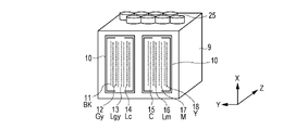
- FIG. 2A, 2B, and 2C are schematic diagrams for explaining the configuration of the recording head 9.
- FIG. 2A is a schematic perspective view showing the direction in which ink is ejected.
- FIG. 2B is an enlarged view of the printing element substrate on the left side of FIG. 2A, and
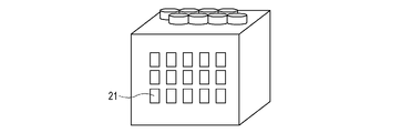
- FIG. 2C is a schematic perspective view showing the connecting portion between the device and the head on the back side of FIG. 2A.
- the recording head 9 has two recording element substrates 10 arranged side by side.
- a plurality of recording element arrays 11 to 14 capable of ejecting black (Bk), gray (Gy), light gray (Lgy), and light cyan (Lc) inks are arranged on one of the recording element substrates.
- a plurality of recording element arrays 15 to 18 capable of ejecting cyan (C), light magenta (Lm), magenta (M) and yellow (Y) inks are arranged on the other recording element substrate. Ink is supplied to each recording element array from an ink common liquid chamber 24 to be described later through an ink flow path inside the recording head 9 .
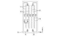
- FIG. 2B is a plan view showing the detailed configuration of the recording element substrate 10.
- two recording element arrays are provided for each ink color.
- Each recording element array is provided with 256 recording elements at a pitch of 600 dpi in the X direction. elements are placed.
- An ejection port is formed in each recording element, and ink droplets are ejected from the ejection port by driving the recording element.
- Temperature sensors S6, S7, S8, and S9 which are diode sensors, are arranged at the ends of the printing element substrate 10 in the X direction, and the temperature of the printing element substrate 10 can be detected.
- the temperature sensors S6 to S9 are arranged at positions about 0.2 mm apart in the sub-scanning direction from the outermost ejection port positions of the recording element arrays, and at intermediate positions between the two recording element arrays in the Y direction.
- Temperature sensors S1, S2, S3, S4, and S5 composed of diodes for detecting the temperature of the central portion of the recording element array are formed in the central portion of the recording element array in the X direction, and these are also two recording element arrays. It is arranged in the middle position sandwiched between
- the sub-heaters 19 and 20 for keeping the print head 9 warm are formed so as to surround the print element substrate 10 and are 1.2 mm outside from the outermost print element row in the Y direction and 0.2 mm from the temperature sensor 53 in the X direction. located outside.
- the connection between the recording head 9 and the main body will be described using FIG. 2C.
- the recording head and the main unit are electrically connected via the contact pads 21 and the flexible substrate wiring 1 shown in FIGS. 1A and 1B. Electrical signals for controlling ink droplet ejection and heat retention, and power consumed by the print head are supplied to the print head via contact pads.
- a receiving mechanism such as a pin may be provided on the main body side for fixing, and the recording head may be fixed by pressing against the main device, thereby stably connecting.
- the power supply for supplying the electric power used for the discharge operation and the power supply for supplying the electric power used for keeping warm may be individually provided with pin wiring, or may be provided with common wiring.
- terminals can be reduced by sharing the pin wiring. Even if the voltages are different, they can be used in common by providing a constant voltage output electronic circuit on the recording head side. It should be noted that the wiring configuration for electrical connection is not limited to that described above.
- FIG. 3 is a cross-sectional view along line AA' in FIG. 2B.
- 27 is a support substrate
- 22 is a recording element
- 23 is an ejection port.
- An ink channel 24 as a channel is formed between the support substrate 27 and the orifice plate 28 , and partition walls (not shown) are provided between the plurality of channels 24 .
- the recording element 22 of this embodiment is an electrothermal conversion element that converts electrical energy into thermal energy to generate heat.
- the recording elements 22 are provided on a support substrate 27 so as to face the ink discharge ports 23 , and a protective film or the like is formed on the surface of the recording elements 22 .
- Ink is supplied to each channel 24 from below in FIG. 3 through a common liquid chamber 26 communicating with each channel 24 .
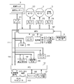
- FIG. 4 is a diagram showing an example of a control circuit of the image recording apparatus.
- a programmable peripheral interface (hereinafter referred to as PPI) 101 receives an instruction signal (command) sent from the host computer 100 and a print information signal including print data, and transfers them to the MPU 102 .
- status information of the image recording apparatus is sent to the host computer 100 as required.
- Data is input/output to/from a console 106 having a setting input unit for a user to make various settings for the image recording apparatus and a display unit for displaying messages to the user. It also receives a signal input from a sensor group 107 including a home position sensor for detecting that the carriage unit 2 or print head 9 is at the home position, a capping sensor, and the like.
- the MPU (Micro Processing Unit) 102 controls each part in the image recording apparatus according to the control program stored in the control ROM 105 .
- a RAM 103 stores received signals, is used as a work area for the MPU 102, and temporarily stores various data.
- the print buffer 121 is a memory area that stores print data developed in the RAM 103 or the like and has a capacity for printing multiple lines.
- the control ROM 105 stores fixed data corresponding to data used in the process of control (for example, data for determining the combination of temperature sensors related to the main part of this embodiment). can be kept. These units are controlled by MPU 102 via address bus 117 and data bus 118 .
- the motor drivers 114, 115 and 116 are motor drivers for driving the capping motor 113, the carriage motor 3 and the paper feed motor 5 under the control of the MPU 102, respectively.
- a sheet sensor 109 detects the presence or absence of a recording medium, that is, whether the recording medium is supplied to a position where recording by the recording head 9 is possible.
- a driver 111 is a driver for driving the recording elements of the recording head 9 according to a recording information signal.
- the environmental temperature/humidity sensor 8 detects the environmental temperature and humidity in the installation environment of the main body of the recording apparatus, as described above. The place where the environmental temperature and humidity sensor 8 is arranged is not limited as long as it can detect the ambient temperature of the device.
- the power supply unit 120 is a power supply unit that supplies power to each of the above units, and includes an AC adapter and a battery as a drive power supply device.
- the power supply unit 120 of this embodiment serves both to supply power for ejecting ink droplets from the print elements of the print head 9 and to supply power to sub-heaters for heat retention.
- a required command is added to the beginning of the data.
- the command includes, for example, the type of recording medium on which recording is performed, the size of the medium, the recording quality, and the presence or absence of automatic object discrimination.
- Types of recording media include, for example, plain paper, OHP sheets, glossy paper, and special recording media such as transfer film, cardboard, and banner paper.
- the medium size is A0 size, A1 size, A2 size, B0 size, B1 size, B2 size, or the like.
- the recording quality includes draft, high quality, medium quality, specific color emphasis, monochrome/color classification, and the like. Further, in the case of adopting a configuration that applies a treatment liquid for improving the fixability of the ink on the recording medium, information that determines whether or not to apply the treatment liquid is transmitted as a command.
- the image recording apparatus reads data necessary for recording from the ROM 105 and performs recording based on those data.
- the data necessary for printing includes, for example, the number of printing passes (the number of scans) when performing multi-pass printing, the amount of ink applied per unit area of the printing medium, and data for determining the printing direction.
- there may be data such as dot size, print medium conveyance conditions, number of colors to be used, and carriage speed.
- FIG. 5 is a diagram showing the amount of electric power used by the heat retaining heater (sub-heater) and the printing element when printing an image such as a poster that uses a lot of ink. Both are electric power supplied from the power supply unit 120 . From left to right, the amount of electric power used by the heater, the amount of electric power used by the recording element for ejecting ink droplets, and the total amount of electric power used by the heater and the recording element are shown.
- Fig. 5(a) shows the power consumption when the environmental temperature is 28°C
- Fig. 5(b) shows the power consumption when the environmental temperature is 13°C.
- the amount indicated by the dashed line is the amount of power that can be used as the recording head.
- the target temperature of the print head is 40° C.
- the difference of which is 27°C. That is, when the ambient temperature is 13° C., more than double the electric power is required to reach the target temperature compared to when the ambient temperature is 28° C.
- the amount of power that can be used indicated by the dashed line is determined by the device configuration, and is constant rather than changing depending on the environmental temperature. Therefore, the amount of electric power that can be used for ejecting ink droplets in the printing element is the amount obtained by subtracting the amount of electric power used by the heater from the amount of electric power that can be used indicated by the dashed line.
- the amount of power used by the recording element varies depending on the recording data, but it is necessary to control the conditions of the recording operation so that the amount of power that can be used by the recording element is within the range. For example, the speed of the carriage is reduced, the area to be printed by one scan of the carriage is reduced, and the like.
- the amount of power that can be used by the printing element without considering the environmental temperature, it is necessary to determine the printing conditions according to the lowest environmental temperature.
- the ambient temperature is 28° C.
- the power consumption of the heater is small and the power can be supplied to the recording element, the power corresponding to the arrow in the figure is not used, and strict recording conditions are set. , which may reduce throughput.
- the amount of electric power used by the heater is taken into consideration based on the ambient temperature, and control is performed so that the amount of electric power that can be used by the printing elements can be fully used. As a result, a decrease in throughput can be suppressed.
- the number of times the recording elements are driven is calculated for each scan, and the carriage operation speed and the number of multi-passes are changed according to the number of times the recording elements are driven.
- FIG. 6 is a flowchart for explaining each process of recording control in this embodiment.
- 102 MPU executes the program stored in the ROM 105 to execute the control of this flow chart.
- step S601 a recording instruction is received from the user.
- the processing flow will be described assuming that the paper type is set to "plain paper” and the recording quality is set to "standard” as the recording conditions.
- step S602 the user's recording command is analyzed and recording mode information is acquired.
- FIG. 7A shows a recording mode table
- FIG. 7B shows a threshold ratio parameter table according to environmental temperature. FIG. 7B will be described in detail later.
- the printing mode table shown in FIG. 7A defines the details of the control contents of the apparatus based on the paper type and printing quality selected by the user. For example, information such as the pass division number, carriage speed, recording element driving count threshold (hereinafter referred to as HDth), and the like is described.
- a recording mode is an internal parameter that defines detailed control over recording. In recent image recording apparatuses, various information such as image processing resolution, error diffusion type, ink type to be used, etc. are defined in various formats and set as recording conditions in order to meet individual preferences of users.
- step S603 the threshold HDth corresponding to the recording mode obtained in step S602 is obtained.
- the printing condition set by the user is plain paper/standard mode
- a value of "115200" is acquired as the threshold HDth.
- the threshold value HDth is set to a value corresponding to the moving speed (carriage speed) of the carriage unit 2 on which the recording head 9 is mounted. This is because the average amount of current per unit time is a load on the electric circuit.
- the threshold value HDth is determined based on the number of times the recording element is driven per unit time. If the driving frequency is the same, the higher the carriage speed, the smaller the value of HDth, and the lower the carriage speed, the larger the value of HDth. is set to be
- the present embodiment is a control aimed at suppressing such excessive loads on electric elements and electric circuits.
- step S604 temperature information indicating the environmental temperature at the start of recording is acquired.
- the room temperature is assumed to be 28°C.
- the environmental temperature is acquired at the timing of receiving the print job in step S601. It is conceivable that the ambient temperature changes during the recording operation, such as when the recording time is extremely long, or when the room temperature rises from a low temperature environment by using an air conditioner to heat the room. In such a case, although the order is different from that of the present embodiment, the environmental temperature may be acquired for each scan, and the timing of acquiring the environmental temperature is not limited to the configuration described above.
- step S605 based on the environmental temperature obtained in step S604, the threshold ratio HDthRatio is obtained according to the threshold ratio parameter table corresponding to the environmental temperature shown in FIG. 7B.
- the threshold ratio parameter table corresponding to the environmental temperature the higher the environmental temperature, the higher the threshold ratio HDthRatio, which is the weighting factor. This is because the higher the ambient temperature, the smaller the amount of electric power required to keep warm using the sub-heater, so that the amount of electric power that can be used for ejection from the print head 9 can be increased.
- 1.2 is acquired as the threshold ratio HDthRatio in accordance with the environmental temperature acquired in step S604 of 28 degrees.
- step S606 the drive count threshold HDth_env is calculated according to the environmental temperature.
- the drive count threshold HDth_env is calculated by multiplying the threshold HDth corresponding to the print mode obtained in step S603 by the threshold ratio HDthRatio obtained in step S605.
- step S607 temperature control is started.
- sub-heaters provided in the print head 9 shown in FIGS. 2A, 2B, and 2C are used to heat until the temperature sensors S6 to S9 reach target values.
- heating control heat retention control
- the target temperature may be changed according to the ink color, the environmental temperature, or the like.
- the present embodiment has a configuration in which a plurality of temperature sensors are provided for one print head, but the head temperature used for determination may be, for example, the average temperature, maximum temperature, or weighted temperature of the plurality of temperature sensors. .
- the head temperature used for determination may be, for example, the average temperature, maximum temperature, or weighted temperature of the plurality of temperature sensors.
- an average value of temperatures acquired by a plurality of temperature sensors is used as the head temperature, but the present invention is not limited to this.
- it is possible to make appropriate changes such as using a weighting coefficient that increases the ratio of temperature sensors that are present in the vicinity of the black ink printing element array.
- the temperature control required for stable ejection will be explained. If ink droplets are not ejected from the recording element during one scan, moisture evaporates from the droplets on the ejection port surface, and the ink viscosity locally increases. This increase in the viscosity of the ink makes it difficult to eject the ink droplets, or shifts the landing position of the ejected ink droplets. On the other hand, the viscosity of the ink can be lowered by controlling the heating or keeping the temperature of the recording head. Therefore, temperature control is performed to heat the print head to a target temperature before starting scanning. The target temperature at this time is set to such a temperature that stable ejection can be obtained even at the timing when one scan is finished. This target temperature can be appropriately set according to the head configuration and ink physical properties, and is set to 40° C. in this embodiment.
- step S608 print data for the next scan is developed in the print buffer 121.
- RGB image data which is general input data
- print data corresponding to each ink color will be described.
- CMYK ink a mode using four colors of CMYK ink
- FIG. 8 is a flowchart showing image processing in the image recording apparatus of this embodiment.
- step S801 RGB original image signals obtained by an image input device such as a digital camera or a scanner, or computer processing, are converted into R'G'B' signals by color processing A.
- the input resolution of the multivalued image data is 600 dpi ⁇ 600 dpi
- the brightness data (R, G, B) are represented by 8 bits and 256 gradations per pixel.
- Color processing A is processing for converting the original image signal RGB into an image signal R'G'B' adapted to the color reproduction range of the printing apparatus.
- step S802 the R'G'B' signal is converted by the color processing unit B into a signal corresponding to each color ink.
- the multi-valued output data of each ink color is converted into data expressed in 12-bit 4096-gradation for each pixel with a resolution of 600 dpi ⁇ 600 dpi.
- the converted signals are density signals C1, M1, Y1, and K1 corresponding to four colors of cyan, magenta, yellow, and black, respectively.
- output values are obtained using a three-dimensional lookup table (3D LUT) for R, G, B inputs and C, M, Y, K outputs. , an interpolation operation is performed using the output values of the grid points around it.
- 3D LUT three-dimensional lookup table
- step S803 gamma correction is performed on the density signals C1, M1, Y1 and K1 using the correction table to obtain C2, M2, Y2 and K2.
- 12-bit data with a resolution of 600 dpi ⁇ 600 dpi for each color is converted into 8-bit 256-gradation data.
- the print data corresponding to each ink color is generated by the image processing flow of steps S801 to S803.
- step S609 the data in the print buffer developed in step S608 is analyzed, and the number of times HDnum of recording elements driven is counted.
- a value obtained by adding up the number of times of driving for four colors of CMYK is treated as the number of times of driving HDnum.
- step S610 the drive count HDnum calculated in step S609 is compared with the drive count threshold HDth_env obtained in step S606, and it is determined whether or not the drive count threshold HDth_env is exceeded. If it is determined to be equal to or greater than the driving number threshold HDth_env, the process proceeds to step S611, and if it is determined to be less than the driving number threshold HDth_env, the process proceeds to step S613.
- step S611 the recording method is determined. Since the drive count HDnum is greater than or equal to the drive count threshold HDth_env, it is necessary to reduce the power consumption per unit time.
- FIG. 9 is a table for setting the recording method. In the setting table shown in FIG. 9, a printing method is set according to a printing mode such as paper type and printing quality. The printing method set here is a printing method that consumes less power per unit time than the printing method that is executed when the process proceeds to step S613, that is, when the driving count is less than the threshold value.
- the threshold ratio DownTh1 indicates the ratio to the drive count threshold HDth_env.
- the drive count threshold HDth_env is multiplied by the threshold ratio, and the multiplied value is compared with the drive count HDnum.
- comparison is performed using a plurality of values as threshold ratios. This makes it possible to estimate the approximate ratio of the drive count HDnum to the drive count threshold HDth_env, and to determine an appropriate recording method.
- FIG. 10 is a flowchart showing processing for determining the recording method using the threshold ratio.
- step S1001 the print mode information obtained in step S602 is obtained.
- step S1002 the values of the threshold ratio DownTh1 for condition 1 and the threshold ratio DownTh2 for condition 2 are obtained from the table in FIG. 9 based on the obtained print mode.
- step S1003 the multiplication value of the drive count threshold HDth_env and the value of the threshold ratio DownTh1 of Condition 1 is calculated, and it is determined whether or not the value of the drive count HDnum is greater than this multiplied value.
- the value of the threshold ratio DownTh1 is 2 in the plain paper/standard mode. Therefore, in this determination, it is determined whether or not the value of the drive count HDnum is greater than twice the drive count threshold HDth_env. If Yes, ie, more than twice, the process proceeds to step S1004. If No, ie, twice or less, the process proceeds to step S1005.
- step S1004 the recording method corresponding to condition 1 is obtained from the table in FIG.
- step S1003 it is determined that the drive count HDnum is greater than twice the drive count threshold HDth_env (condition 1). should be halved or less. Therefore, a recording method is set in which the carriage speed during scanning is 0.6 times the standard speed and the recording data for the next scan is divided into two.
- the horizontal direction is the scanning direction (Y direction) of the recording head 9
- the vertical direction is the direction (X direction) in which the recording elements are arranged.
- an image printed in one scan is shown, and the length in the vertical direction corresponds to the length that the printhead 9 can print in one scan, that is, the width of the array of printing elements. Note that only one row of printing elements of the printing head is shown in this figure.
- FIG. 11A is a case of printing without division, and shows an image printed in one scan using all the printing elements arranged in the printing head.
- FIG. 11B shows an image recorded with two scans divided into two.
- the 512 recording elements arranged in the recording head 9 are divided into an upper half and a lower half, and the 1st to 256th recording elements in the upper half are used for recording in the first scan, and the 257th to 257th recording elements in the lower half are used in the second scan. Printing is performed using the 512th printing element.
- a method of thinning print data using a mask pattern may be used as a dividing method.
- step S1005 the multiplication value of the drive count threshold HDth_env and the value of the threshold ratio DownTh2 of condition 2 is calculated, and it is determined whether or not the drive count HDnum value is greater than this multiplied value.
- the value of the threshold ratio DownTh2 in the plain paper/standard mode is 1.5. Therefore, in this determination, it is determined whether or not the value of the drive count HDnum is greater than 1.5 times the drive count threshold HDth_env. If it is larger, the process proceeds to step S1006, and if it is smaller, the process proceeds to step S1007.
- step S1006 the recording method corresponding to condition 2 is obtained from the table in FIG.
- step 1005 it is determined that the drive count HDnum is greater than 1.5 times and smaller than 2 times the drive count threshold HDth_env (condition 2). , the power consumption per unit time must be reduced to 2/3 or less. Therefore, a recording method is set in which the carriage speed during scanning is 0.6 times the standard speed.
- step S1007 it is determined that the drive count HDnum is larger than the drive count threshold HDth_env and smaller than 1.5 times (condition 3). set.
- step S611 the recording condition is set according to the ratio of the drive count HDnum to the drive count threshold HDth_env.
- a recording condition is set in which power consumption per unit time is smaller than when the driving number HDth is smaller than the driving number threshold HDth_env. Accordingly, an image can be recorded within a predetermined power consumption range.
- the setting method of the recording method is not limited to the setting method of this embodiment.
- power consumption can be suppressed by calculating the ratio of the value of the number of times of driving HDnum to the reference value and changing the carriage speed based on the reciprocal.
- the number of divisions of the print data may be increased to three or four.
- a form in which condition 2 is not defined, such as the clean mode for plain paper, may also be used. In this case, the process advances to step S1007 to set the printing method without branching to step S1005.
- step S612 the data in the print buffer is regenerated. If the printing method for split printing is set in step S611, print data corresponding to split printing is generated in the print buffer. In this embodiment, the number of divisions is 2, and data for one scan is divided into two to generate print data for two scans, as described with reference to FIGS. 11A and 11B.
- step S613 an image is printed on the print medium based on the print data on the print buffer.
- step S612 an image is printed by N scans based on print data for N scans corresponding to the number N of divisions. Further, in the printing method set in step S611, if it is set to change the carriage speed, the carriage unit 2 is controlled based on the set printing conditions.
- step S614 it is determined whether or not recording has ended. If printing is not completed and print data still remains, the process returns to step S608 to generate print data for one scan and continue the print processing.
- the control of this embodiment is particularly effective when the power supply for supplying power to the recording element and the power supply for supplying power to the sub-heater are treated as one power supply capacity. This is because electrical components such as substrates, wiring, and power supplies require control to keep the instantaneous amount of applied current and the average amount of applied current below a predetermined threshold. On the other hand, even if the power supply for the printing element and the power supply for the sub-heater are configured separately, it may be necessary to suppress the maximum power consumption during normal operation of the image recording apparatus. Even in such a case, the configuration of this embodiment can be applied. For example, a configuration that does not include a sub-heater for keeping the temperature of the print head warm may be used.
- Insulation control of the print head can be performed by applying a pulse to the extent that ink droplets are not ejected to the print element, which is an electrothermal conversion element, other than in the case of using a sub-heater. Even in such a form, the premise that the amount of electric power that can be used to keep the print head warm differs depending on the environmental temperature is the same. Therefore, the same effect can be obtained by applying the above configuration of the present embodiment. be able to.
- the sub-heaters are arranged so as to surround the periphery of the print element substrate 10.
- the present invention is not limited to this form, and various layouts such as wiring along the print element array can be considered. be done.
- the threshold ratio HDhRatio described in the threshold ratio parameter table according to the environmental temperature in FIG. 7B is changed only by the environmental temperature regardless of the recording mode.
- the threshold ratio HDhRatio may be set in consideration of the carriage speed set for each print mode.
- the type of ink and the number of inks used may differ depending on the print mode, such as monochrome mode and color mode, the threshold ratio parameter table is extended for each print mode, and the value may be used.
- recent image recording apparatuses may include an ink circulation mechanism or an ink temperature control apparatus.
- the temperature of the ink flowing into the print head may be obtained and used as the environmental temperature for determination.
- the temperature of the recording head 9 is considered to be substantially equal to the temperature in the installation environment of the recording apparatus. Therefore, under such conditions, the temperature obtained by the temperature sensors S6 to S9 may be used as the environmental temperature in this embodiment. In this case, it is preferable not to obtain the environmental temperature for each scan, but to continue using the temperature obtained before the start of the printing operation as the environmental temperature.
- step S609 of FIG. 6 the number of times HDnum of printing elements is driven is counted based on multi-valued data of 256 gradations, but the present invention is not limited to this form.
- quantized data indicating the actual ejection or non-ejection of ink from the printing elements is generated.
- the number of times of driving HDnum is counted. It may be in the form of Further, the method is not limited to counting the number of times the printing elements are driven, and a method of acquiring a dot count value and comparing it with a threshold value may be used. It may be in the form of
- the image recording apparatus of this embodiment is not limited to a serial recording type recording apparatus, and can also be applied to a so-called full multi-type image recording apparatus in which a recording medium is conveyed to a fixed recording head.
- a recording medium is conveyed to a fixed recording head.
- one print head may have a plurality of ink colors, or a print head may be provided for each ink color.
- the printing method is determined by counting the number of times the printing elements are driven for each scan.
- the recording method may be determined by counting the number of times of driving.
- power consumption per unit time can be suppressed by slowing down the transport speed of the recording medium.
- the amount of power used for keeping the printhead warm is described as the power required in addition to the amount of power used for ejecting ink. good too.
- parameters such as HD_Ratio may be set in consideration of the amount of electric power of the fixing mechanism, as in the case of a sub-heater for heat retention.
- a device capable of setting the fixing temperature during the fixing period is generally used.
- HD_Ratio can be set in consideration of the set temperature in the fixing period so as to correspond to the application.
- FIG. 12 is a flowchart for explaining each process of recording control in this embodiment. The description of the points that overlap with the steps in FIG. 6 of the first embodiment will be omitted.
- steps S1201 and S1202 are the same as that of steps S601 and S602, so the description is omitted.
- step S1203 the drive number threshold HDth corresponding to the print mode acquired in step S1202 and the drive number threshold HDth_narrow in the small divided area are acquired.
- FIG. 13A is a table in which the drive count threshold HDth corresponding to each print mode is set, and the value of the threshold HDth_narrow used for comparison with the drive count of the divided regions is added. Since FIG. 13B is the same as FIG. 7B, description thereof is omitted.
- the case where the plain paper/standard mode is set will be described as an example.
- Steps S1204 and S1205 are the same processes as steps S605 and S605, so the description is omitted.
- step S1206 two values, a drive number threshold HDth_env and a divided area threshold HDth_env_narrow, are calculated according to the environmental temperature.
- the calculation method is the same as in step S606, and HDth and HDth_narrow are each multiplied by HDthRatio.
- Steps S1207 to S1209 are the same processing as steps S607 to S609, so description thereof will be omitted.
- step S1210 the number of times the recording elements are driven in the divided areas is counted.
- step S1209 the number of times the recording elements are driven is counted based on the print data for one scan. HDnum_narrow.
- FIG. 14A, 14B, and 14C are image diagrams showing print buffers for one scan of a certain ink color.
- the number of printing elements A is 512 nozzles
- FIG. 14A shows the whole scan
- FIG. 14B shows the count of the number of times the divided area is driven for the first time
- FIG. 14C shows the count of the number of times the divided area is driven for the second time.
- the width of the divided area in the recording element array direction is 512 nozzles, which is the same as the area for one scan.
- step S1209 first, the number of times of driving the area for one scan shown in FIG. 14A is counted. Next, the number of driving times of the divided regions indicated by dashed lines in FIG. 14B is counted. Next, the number of driving times of the divided regions indicated by broken lines in FIG. 14C is counted. As shown in FIGS. 14B and 14C, the divided areas counted the first time and the divided areas counted the second time are set so as to partially overlap. In this way, the number of times of driving is counted while shifting the divided regions, and the maximum value in one scanning region is calculated. This maximum value is determined as the drive count HDnum_narrow in the divided area.
- print buffers for four colors of CMYK may be developed at the same time and HDnum_narrow may be determined by the total value of four colors.
- HDnum_narrow may be determined by the total value of four colors.
- step S1211 it is determined whether or not the number of times of driving is greater than or equal to the threshold. Specifically, it is determined whether or not the drive count HDnum for one scan region is greater than or equal to the drive count threshold HDth_env for one scan region, and whether or not the drive count HDnum_narrow for the divided region is greater than or equal to the drive count threshold HDth_env_narrow for the divided region. If determined to be equal to or greater than the threshold, the process proceeds to step S1212, and if determined to be smaller than the threshold, the process proceeds to step S1214.
- step S1212 the recording method is determined. This determination method is the same as step S611.
- the process in step S611 is similarly performed for the drive count HDnum_narrow of the divided area. If the conditions for the recording method determined by the number of times HDnum of driving for one scan and the number of times of driving HDnum_narrow of the divided areas are different, the one with the smaller condition number should be selected. For example, if the recording method obtained by HDnum is condition 2 and the recording method obtained by HDnum_narrow is condition 1, the recording method of condition 1 is selected.
- step S1213 to step S1215 is the same as the processing from step S612 to step S614, so the description is omitted.
- the number of times the recording element is driven is counted and compared with the threshold value. can also suppress a decrease in throughput.
- the configuration in which the same recording method is selected for one scan area and divided areas has been described, but they do not have to be the same.
- a form in which the recording method is set individually may be used.
- the recording method is determined by comparing each of the one-scan area and the divided areas with the threshold value, but the recording method may be determined only by comparing the divided areas.
- the size of the divided area is not limited to the above example, and the width in the X direction may be shorter than the width of one scan.
Landscapes
- Ink Jet (AREA)
- Particle Formation And Scattering Control In Inkjet Printers (AREA)
Abstract
記録装置の温度に基づいて閾値を設定し、設定された閾値を記録素子の駆動回数をカウントした値と比較することにより、取得した温度に応じた記録条件を設定する。
Description
本発明は、記録媒体上に画像を記録するための画像処理装置、画像処理方法、記録装置及びプログラムに関する。
記録装置で使用される記録ヘッドとして、インク滴を吐出することにより記録媒体上にドットを付与して画像を記録する、所謂インクジェット記録ヘッドが知られている。インクジェット記録ヘッドを搭載した記録装置では、インクタンクから供給流路を介してインクが供給され、ユーザから指定された画像データに基づいて、記録ヘッドを制御することにより画像が記録される。
ホストコンピュータから送られてくる画像データによっては、記録されるドットの密度が一様ではなく、領域によってインク滴を吐出するための記録素子の駆動に必要な電力が変動する場合がある。このような電力の変動を考慮せずに、常に一定の生産性を確保しようとすると、記録されるドット密度が最大の場合に対応する必要がある。その結果、大容量電源と、大容量電源の入出力に耐えうる回路を備える必要がある。また、記録の高速化という要望に応じるため、記録ヘッドに設けられた記録素子が高密度化且つ長大化している。これに伴い、記録ヘッドで使用される電力が増加しているという課題がある。
特許文献1には、これから画像が記録される領域における記録素子の駆動回数を計測し、駆動回数が所定閾値よりも大きい場合、記録ヘッドを搭載したキャリッジを減速させる、もしくは、当該領域の記録を複数回のスキャンに分割する構成が記載されている。このように、記録動作の前に記録データを解析することにより、記録ヘッドで消費される電力を抑え、装置の一定電源容量を最大限に利用しつつ、スループットの低下を抑制することができる。
しかしながら、特許文献1に記載の技術では、記録装置の設置環境における温度は考慮されていない。本発明は、記録装置の設置環境における温度に基づいて記録条件を決定することを目的とする。
本発明は、記録媒体上にインク滴を付与することにより画像を記録する記録装置であって、前記記録装置の設置環境における温度を取得する取得手段と、電気エネルギーが印加されることによって駆動される複数の記録素子を備える記録ヘッドと、前記記録ヘッドと記録媒体とを相対走査させる走査手段と、記録の指示に応じて、前記取得手段により取得された温度に対応する閾値を設定する設定手段と、前記記録の指示に基づき、1回の相対走査において所定の領域にインク滴を付与するための前記複数の記録素子の駆動に関する値を算出する算出手段と、前記設定手段により設定された前記閾値と、前記算出手段により算出された前記駆動に関する値と、に基づき、画像を記録するための記録条件を決定する決定手段と、前記決定手段により決定された前記記録条件に基づき、前記記録ヘッド及び前記走査手段を制御する制御手段と、を備えることを特徴とする。
本発明により、記録装置の設置環境における温度に基づいて記録条件を決定することができる。
(第1の実施形態)
以下、図面を参照して、本発明の一実施形態を説明する。
以下、図面を参照して、本発明の一実施形態を説明する。
<装置全体概略>
図1Aは、本実施形態に係るインクジェット記録装置(以下、画像記録装置とも呼ぶ)の外観図である。本実施形態のインクジェット記録装置は、所謂シリアルスキャン型の画像記録装置であり、記録媒体Pの搬送されるX方向と交差するY方向に記録ヘッドが搭載されたキャリッジをスキャン(走査)させる。このスキャンの間に記録ヘッド9に設けられた記録素子を駆動することによりインク滴が付与され、記録媒体P上に画像を記録する。図中、X方向は記録媒体Pが搬送される方向、Y方向はキャリッジが走査する方向、Z方向はX方向及びY方向とそれぞれ交差する方向である。
図1Aは、本実施形態に係るインクジェット記録装置(以下、画像記録装置とも呼ぶ)の外観図である。本実施形態のインクジェット記録装置は、所謂シリアルスキャン型の画像記録装置であり、記録媒体Pの搬送されるX方向と交差するY方向に記録ヘッドが搭載されたキャリッジをスキャン(走査)させる。このスキャンの間に記録ヘッド9に設けられた記録素子を駆動することによりインク滴が付与され、記録媒体P上に画像を記録する。図中、X方向は記録媒体Pが搬送される方向、Y方向はキャリッジが走査する方向、Z方向はX方向及びY方向とそれぞれ交差する方向である。
図1A及び図1Bを用い、画像記録装置の構成および記録時の動作の概略を説明する。まず、スプール6に記録媒体Pが保持されている状態から、不図示の給紙モータによりギヤを介して給紙ローラが駆動され、記録ヘッド9が記録可能な位置まで記録媒体Pが給紙搬送される。一方、所定の搬送位置において、不図示のキャリッジモータにより記録ヘッド9を搭載したキャリッジユニット2を、図のY方向に延在するガイドシャフト29に沿ってスキャンさせる。尚、記録ヘッド9は、キャリッジユニット2に着脱可能に搭載されている。そして、1回のスキャンが実行される間に、エンコーダ7によって得られる位置信号に基づいたタイミングで、記録ヘッド9に設けられた記録素子が駆動される。この記録素子の駆動により、吐出口(ノズル)からインク滴が吐出され、記録媒体P上に着弾する。記録ヘッド9の1回のスキャンにおいて、記録ヘッド9に設けられた記録素子の配列範囲に対応した領域に対して画像を記録することができる。この記録素子の配列範囲に対応した記録幅を、バンド幅と呼ぶ。本実施形態において、キャリッジユニット2のスキャン速度は毎秒40インチであり、記録解像度は、1インチあたり1200ドット、すなわち1200dpi(ドット/インチ)とする。
1回のスキャンの後、記録媒体PがX方向に所定量搬送される。その後、次のスキャンで、次のバンド幅分の領域に対して画像が記録される。尚、画像記録装置は、各スキャンの間にバンド幅、すなわち記録素子の配列範囲分を搬送する形態であってもよく、1スキャン毎に記録媒体Pを搬送せずに複数回のスキャンの後に搬送する形態であってもよい。また、n回のスキャンにおいては間引かれたデータに基づいてインクを付与し、各スキャンの間は1/nバンド分の幅の搬送を繰り返すことで、同一領域に対して記録に用いる記録素子を異ならせて画像を完成させる方法(所謂マルチパス記録)であってもよい。
詳しくは図1Bを用いて後述するが、本実施形態の記録ヘッド9には、インクを吐出するための複数の記録素子が図のX方向に配列している。そして、記録ヘッド9には、各記録素子を駆動するための信号パルスやヘッド温調用信号などを供給するためのフレキシブル配線基板1が取り付けられており、フレキシブル配線基板1の他端は、画像記録装置の制御を実行する制御回路に接続されている。
キャリッジモータからキャリッジユニット2への駆動力の伝達には、キャリッジベルトを用いることができる。キャリッジベルトの代わりに、例えば、キャリッジモータにより回転駆動され、主走査方向に延在するリードスクリュと、キャリッジユニット2に設けられ、リードスクリュの溝に係合する係合部とを具えたものなど、他の駆動方式を用いることも可能である。
給紙搬送された記録媒体Pは、給紙ローラとピンチローラとに挟持搬送され、プラテン4上の記録位置、すなわち記録ヘッド9の主走査領域に導かれる。尚、休止状態においては、記録ヘッド9のフェイス面がキャップされているため、記録に先立ってキャップを開放し、記録ヘッド9ないしキャリッジユニット2をスキャン可能状態にする。そして、1スキャン分の記録データがバッファに蓄積されると、キャリッジモータ3によりキャリッジユニット2をスキャンさせ、上述のように記録媒体P上に画像が記録される。
本図において、環境温湿度センサ8が破線で示されている。一般的に、環境温湿度センサ8は、誤差や測定ノイズを排除するため、モータやヒータな振動源や発熱源となる部材から離れた位置に配置されている。本来は装置裏側など視認されにくい位置に具備されるが、本明細書中では、説明上、透過した形態で記している。
図1Bは、シリアルスキャン方式の記録装置における、記録媒体Pと記録ヘッドの動作を示す概略図であり、記録ヘッド9と記録媒体Pを上から見た図である。本図を用いて、シリアル記録方式の動作について説明する。キャリッジモータ3の駆動により、キャリッジユニット2に搭載された記録ヘッド9は、記録媒体Pの搬送方向(X方向)と直交する幅方向(Y方向)に、往復走査する。前述したように、シリアル記録方式の画像記録装置においては、記録ヘッド9と記録媒体Pとの相対走査により、同一領域に対してインク滴を吐出する記録素子を異ならせるマルチパス記録を行うことができる。このマルチパス記録により、記録素子毎の記録特性にばらつきによる濃度ムラを抑制することができる。
<記録ヘッド構成>
図2A、図2B及び図2Cは、記録ヘッド9の構成を説明するための模式図である。図2Aは、インクが吐出される方向から示した模式的斜視図である。図2Bは、図2Aの左側の記録素子基板の部分を拡大したものであり、図2Cは、図2A裏面の、装置とヘッドとの接続部分を示した模式的斜視図である。
図2A、図2B及び図2Cは、記録ヘッド9の構成を説明するための模式図である。図2Aは、インクが吐出される方向から示した模式的斜視図である。図2Bは、図2Aの左側の記録素子基板の部分を拡大したものであり、図2Cは、図2A裏面の、装置とヘッドとの接続部分を示した模式的斜視図である。
図2Aにおいて、記録ヘッド9には、2つの記録素子基板10が並置されている。一方の記録素子基板には、ブラック(Bk)、グレー(Gy)、ライトグレー(Lgy)、ライトシアン(Lc)のインクを吐出可能な複数の記録素子列11~14が配列されている。他方の記録素子基板には、シアン(C)、ライトマゼンタ(Lm)、マゼンタ(M)およびイエロー(Y)のインクを吐出可能な複数の記録素子列15~18が配列されている。各記録素子列に対しては、後述のインク共通液室24から記録ヘッド9内部のインク流路を介してインクが供給される。
図2Bは、記録素子基板10の詳細な構成を示す平面図である。記録ヘッド9に並置される2つの記録素子基板のうち、記録素子列11~14が配列された記録素子基板である。尚、本実施形態において、各インク色について2列の記録素子列が設けられている。各記録素子列には、X方向において600dpiのピッチで256個の記録素子が設けられており、さらに、向かい合う記録素子列に対して半ピッチ、すなわち1200dpiずれた状態で、各色計512個の記録素子が配置されている。そして、各記録素子には吐出口が形成されており、記録素子の駆動によって吐出口からインク滴が吐出される。また、X方向において記録素子基板10上の端部には、ダイオードセンサである温度センサS6、S7、S8、S9が配置されており、記録素子基板10の温度を検出することができる。温度センサS6~S9は、記録素子列の最も外側の吐出口位置から副走査方向に約0.2mm離れた位置であって、Y方向において2つの記録素子列の中間位置に配置されている。X方向において記録素子列の中央部には、記録素子列の中央部の温度を検出するためのダイオードからなる温度センサS1、S2、S3、S4、S5が形成され、これらも2つの記録素子列に挟まれた中間位置に配置されている。
記録ヘッド9を保温するためのサブヒータ19及び20は、記録素子基板10を取り囲むようにして形成され、Y方向において最外記録素子列から1.2mm外側、X方向において温度センサ53から0.2mm外側に位置する。
図2Cを用い、記録ヘッド9と本体との接続について説明する。コンタクトパッド21を介し、図1A及び図1Bのフレキシブル基板配線1を通じて、記録ヘッドと本体装置が電気的に接続される。インク滴の吐出や保温を制御する電気信号、また、記録ヘッドで消費される電力が、コンタクトパッドを介して、記録ヘッドに供給される。接続の際は、固定として本体側にピンのような受け機構を用意し、記録ヘッドを本体装置に押圧して固定することで、安定的に接続される構成をとっても良い。また、吐出動作に使用される電力を供給する電源と保温に使用される電力を供給する電源は、個別にピン配線を具備してもよいし、共通の配線としてもよい。吐出で使用する電圧値と保温で使用する電圧値が共通であれば、ピン配線を共通にすることによって端子を減らすことができる。また、電圧が異なる場合であっても、記録ヘッド側に一定電圧出力電子回路を具備することにより、共通にすることができる。尚、上記のような電気接続の配線構成に限定されるものではない。
図3は、図2Bの線A-A′に沿う断面図である。本図において、27は支持基板、22は記録素子、23は吐出口である。また、流路としてのインク流路24は支持基板27とオリフィスプレート28との間に形成され、複数の流路24の間には不図示の隔壁が設けられている。本実施形態の記録素子22は、電気熱変換素子であり、電気エネルギーを熱エネルギーに変換して発熱する。記録素子22は、インク吐出口23と対向するように支持基板27に設けられており、記録素子22の表面には保護膜などが形成されている。そして、図3中の下方から各流路24に連通する共通液室26を介し、各流路24にインクが供給される。
<制御系の構成例>
図4は、画像記録装置の制御回路の一例を示す図である。プログラマブル・ペリフェラル・インターフェイス(以下PPIとする)101は、ホストコンピュータ100から送られてくる指令信号(コマンド)や記録データを含む記録情報信号を受信してMPU102に転送する。それとともに、ホストコンピュータ100に対しては必要に応じ画像記録装置のステータス情報を送出する。また、ユーザが画像記録装置に対して各種設定を行う設定入力部やユーザに対してメッセージを表示する表示部などを有したコンソール106との間で、データの入出力を行う。また、キャリッジユニット2ないし記録ヘッド9がホームポジションにあることを検出するホームポジションセンサや、キャッピングセンサなどを含むセンサ群107よりの信号の入力を受容する。
図4は、画像記録装置の制御回路の一例を示す図である。プログラマブル・ペリフェラル・インターフェイス(以下PPIとする)101は、ホストコンピュータ100から送られてくる指令信号(コマンド)や記録データを含む記録情報信号を受信してMPU102に転送する。それとともに、ホストコンピュータ100に対しては必要に応じ画像記録装置のステータス情報を送出する。また、ユーザが画像記録装置に対して各種設定を行う設定入力部やユーザに対してメッセージを表示する表示部などを有したコンソール106との間で、データの入出力を行う。また、キャリッジユニット2ないし記録ヘッド9がホームポジションにあることを検出するホームポジションセンサや、キャッピングセンサなどを含むセンサ群107よりの信号の入力を受容する。
MPU(マイクロプロセッシングユニット)102は、制御用ROM105に記憶された制御プログラムに従って、画像記録装置内の各部を制御する。RAM103は、受信した信号を格納し、あるいはMPU102のワークエリアとして使用され、また各種データを一時的に記憶する。プリントバッファ121は、RAM103等に展開された記録データを記憶し、複数行記録分の容量を持つメモリ領域である。制御用ROM105には、上記制御プログラムのほか、後述する制御の過程で使用されるデータ(例えば本実施形態の主要部に係る温度センサの組み合わせを定めるためのデータ)等に対応した固定データを格納しておくことができる。これらの各部は、アドレスバス117およびデータバス118を介し、MPU102により制御される。
モータドライバ114、115および116は、それぞれ、キャッピングモータ113、キャリッジモータ3および給紙モータ5をMPU102の制御に応じて駆動するためのモータドライバである。
シートセンサ109は、記録媒体の有無、すなわち記録媒体が記録ヘッド9による記録が可能な位置に供給されたか否かを検知する。ドライバ111は、記録情報信号に応じて記録ヘッド9の記録素子を駆動するためのドライバである。環境温湿度センサ8は、前述のように、記録装置本体の設置環境における環境温度および環境湿度を検出する。装置の周辺温度を検出できる構成であれば、環境温湿度センサ8が配置される場所については限定されない。
電源部120は、上記各部へ電源を供給する電源部であり、駆動電源装置としてACアダプタと電池とを備える。尚、本実施形態の電源部120は、記録ヘッド9の記録素子からインク滴を吐出するための電力を供給する役割と、保温のためのサブヒータに電力を供給する役割の両方を担っている。
画像記録装置およびホストコンピュータ100からなる記録システムにおいて、ホストコンピュータ100よりパラレルポート、赤外線ポート、あるいはネットワーク等を介して記録データを送信する際、その先頭部分に所要のコマンドが付加される。そのコマンドとしては、例えば、記録の行われる記録媒体の種類、媒体サイズ、記録品位、およびオブジェクトの自動判別の有無などがある。記録媒体の種類としては、例えば、普通紙、OHPシート、光沢紙等、さらには転写フィルム、厚紙、バナー紙等の特殊な記録媒体の種別がある。媒体サイズは、A0判、A1判、A2判、B0判、B1判、B2判などである。記録品位は、ドラフト、高品位、中品位、特定色の強調、モノクローム/カラーの種別などがある。また、記録媒体でのインクの定着性を向上するための処理液を付与する構成が採用される場合には、その付与の有無を定める情報がコマンドとして送信される。
これらのコマンドに従い、画像記録装置側では、ROM105から記録に必要なデータを読み込み、それらのデータに基づいて記録を行う。記録に必要なデータとしては、例えば、上述したマルチパス記録を行う際の記録パス数(スキャン回数)や、記録媒体単位面積あたりのインクの打ち込み量、および、記録方向等を決定するデータがある。また、マルチパス記録を行う際に適用されるデータ間引き用のマスク種類、記録ヘッド9内の温度センサ検出値に基づく駆動条件(たとえば発熱部に印加する駆動パルスの形状,印加時間等)がある。さらに、ドットのサイズ、記録媒体搬送の条件、使用する色数、さらにはキャリッジ速度等のデータがあってもよい。
<環境温度の違いに起因する使用電力量>
次に、本実施形態で課題とする環境温度の違いに起因する使用電力量について説明する。ここでは、環境温度28℃と13℃の2つの条件を比較して詳細に説明する。
次に、本実施形態で課題とする環境温度の違いに起因する使用電力量について説明する。ここでは、環境温度28℃と13℃の2つの条件を比較して詳細に説明する。
図5は、インクを多く使うポスターのような画像を記録する際の、保温ヒータ(サブヒータ)と記録素子の使用電力量を示した図である。いずれも、電源部120から供給される電力である。左から、保温ヒータで使用される電力量、記録素子においてインク滴の吐出に使用される電力量、保温ヒータと記録素子で使用される電力量の合計を示している。図5(a)は、環境温度が28℃の時の使用電力量、図5(b)は、環境温度が13℃の時の使用電力量である。図中、破線で記されている量は、記録ヘッドとして使用可能な電力量である。
記録ヘッドの目標温度を40℃とすると、図5(a)の環境温度28℃の場合、その差分である12℃分の加熱が必要であり、図5(b)の環境温度13℃の場合、その差分である27℃分の加熱が必要である。すなわち、環境温度が13℃の場合、環境温度が28℃の場合に比べて、目標温度に到達するまでに倍以上の電力が必要である。
一方、破線で示される使用可能な電力量は装置構成で定まるものであり、環境温度によって変化するものではなく一定である。従って、記録素子においてインク滴の吐出に使用できる電力量は、破線で示した使用可能な電力量から、保温ヒータで使用される電力量を減算した量である。
前述したように、環境温度が異なる場合には、目標温度からの差分が大きい方が記録素子で使用できる電力量が小さく、目標温度からの差分が小さい方が記録素子で使用できる電力量が大きくなる。実際の記録において、記録素子で使用される電力量は記録データによって異なるが、記録素子で使用可能な電力量の範囲内に収まるように記録動作の条件を制御する必要がある。例えば、キャリッジ速度を落とす、1回のキャリッジの走査で記録する領域を小さくする等である。環境温度を考慮せずに記録素子で使用可能な電力量を設定する場合には、最も環境温度が低い場合に合わせて記録条件を決定する必要がある。その場合、例えば環境温度28℃の場合には、保温ヒータの使用電力が少なく、記録素子に電力を回せるにもかかわらず、図中矢印分の電力を使用せずに、厳しい記録条件が設定され、スループットが低下する可能性がある。これに対し、本実施形態では、環境温度に基づいて保温ヒータにおいて使用される電力量を勘案し、記録素子で使用可能な電力量を余すことなく使用できるように制御する。この結果、スループットの低下を抑制することができる。尚、本実施形態では、このような構成に加え、スキャン毎に記録素子駆動回数を算出し、記録素子駆動回数に応じてキャリッジ動作速度やマルチパス数を変更する。
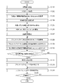
図6は、本実施形態の記録制御の各工程を説明するためのフローチャートである。ROM105に記憶されたプログラムを102MPUが実行することにより、本フローチャートの制御が実行される。
まず、ステップS601において、ユーザからの記録の指示を受信する。ここでは、記録条件として用紙種が「普通紙」、記録品位が「標準」が設定された場合を想定し、処理フローを説明する。
ステップS602において、ユーザの記録命令を解析し、記録モード情報を取得する。ここで、図7Aは記録モード表、図7Bは環境温度に応じた閾値比率パラメータ表を示している。図7Bについては後に詳しく説明する。
図7Aに示す記録モード表には、ユーザにより選択された用紙種及び記録品位に基づき、装置の制御内容の詳細が定義されている。例えば、パス分割数やキャリッジ速度、記録素子駆動回数閾値(以後HDth)などの情報が記載されている。記録モードとは、記録を行う際に詳細な制御を定義する、内部的なパラメータのことである。昨今の画像記録装置では、ユーザの個別嗜好性に対応するため、画像処理解像度や誤差拡散種類、使用するインク種類などの様々な情報が様々なフォーマットで定義され、記録条件として設定される。
ステップS603において、ステップS602にて取得された記録モードに応じた閾値HDthを取得する。ここでは、ユーザにより設定された記録条件が普通紙・標準モードである場合を想定し、閾値HDthとして「115200」という値が取得される。
ここで、閾値HDthについて説明する。本実施形態の画像記録装置は、記録素子数が1色当たり512ノズル、インク色数がCMYKの4色、走査方向(Y方向)の最大可能記録幅が10inch、記録素子の駆動解像度が600dpi、という装置構成を想定している。このようなプリンターにおいて、1スキャン内での記録素子駆動回数(以後HDnum)の最大値は、1色当たり512ノズル×10inch×600dpi=307200回である。ただし、装置の電源構成や電気端子などの許容電流量などの制約により、実際に記録ヘッドに吐出用の電流として流してよい電流量が閾値HDthとして定められている。閾値HDthは、記録ヘッド9を搭載したキャリッジユニット2の移動速度(キャリッジ速度)に応じた値が設定される。これは、単位時間当たりの平均電流量が、電気回路への負荷となるためである。キャリッジ速度が異なる複数の記録モードが設定可能な場合、記録媒体P上に吐出されるドット数が同じであっても、キャリッジ速度に応じて単位時間当たりの記録素子駆動回数が異なる。従って、閾値HDthは、単位時間当たりの記録素子駆動回数に基づいて定められており、同じ駆動周波数であれば、キャリッジ速度が速ければHDthの値が小さく、キャリッジ速度が遅ければHDthの値が大きくなるように設定されている。本実施形態は、このような電気素子や電気回路の過剰な負荷を抑制することを目的とした制御である。
ステップS604において、記録開始時の環境温度を示す温度情報を取得する。ここでは高温環境を想定し、室温は28℃とする。尚、本実施形態においては、ステップS601にて記録ジョブを受け取ったタイミングで環境温度を取得する構成とする。尚、記録時間が非常に長い場合や、空調を使用して室内を温めることによって低温環境から室温が上がった場合のように、記録動作中に環境温度が変化する状況が考えられる。そのような場合には、本実施形態とは順番が異なるが、スキャン毎に環境温度を取得してもよく、環境温度を取得するタイミングについては上記構成に限定されない。
ステップS605において、ステップS604にて得られた環境温度に基づき、図7Bに示す環境温度に応じた閾値比率パラメータ表に従って、閾値比率HDthRatioを取得する。環境温度に応じた閾値比率パラメータ表においては、環境温度が高いほど、重みづけ係数である閾値比率HDthRatioが高くなるように設定されている。これは、環境温度が高いほどサブヒータを用いて保温するために必要な電力量小さくなるため、記録ヘッド9からの吐出に使用できる電力量を多くすることができるためである。ここでは、ステップS604にて取得された環境温度が28度に応じて、閾値比率HDthRatioとして1.2が取得される。
ステップS606において、環境温度に応じた駆動回数閾値HDth_envを算出する。駆動回数閾値HDth_envは、ステップS603にて取得された記録モードに応じた閾値HDthと、ステップS605にて取得された閾値比率HDthRatioとを乗算することによって算出される。
ステップS607において、温調制御を開始する。温調制御には、図2A、図2B及び図2Cで示した記録ヘッド9に設けられたサブヒータを用い、温度センサS6~S9が目標値に到達するまで加熱する。本実施形態では、目標温度に到達した後であっても記録データが存在している間は、目標温度をキープできるように加熱制御(保温制御)を続けるものとする。ここでは、目標温度を一定とする場合について説明するが、インク色や環境温度などに応じて目標温度を変更する形態であってもよい。
本実施形態は1つの記録ヘッドに対して複数の温度センサを備える構成であるが、判定に用いるヘッド温度は、例えば、複数の温度センサの平均温度や最高温度、重みづけしたものなどが考えられる。ここでは、複数の温度センサが取得した温度の平均値をヘッド温度として用いるが、これに限られるものではない。例えば、モノクロモードで画像を記録する場合は、黒インクの記録素子列近傍に存在する温度センサの比率を大きくした重みづけ係数を用いる等、適宜変更可能である。
ここで、安定吐出に必要となる温調制御について説明する。1スキャンの間中、記録素子からインク滴が吐出されなかった場合、吐出口表面の液滴から水分が蒸発し、インク粘度が局所的に上昇する。このインクの増粘により、インク滴が吐出されづらくなったり、吐出されたインク滴の着弾位置がずれたりする。一方、記録ヘッドを加熱または保温する制御によってインクの粘度を下げることができる。このため、スキャン開始前に記録ヘッドを目標温度まで加熱する温調制御を行う。このときの目標温度を、1回のスキャンが終了したタイミングにおいても安定吐出を得られるような温度に設定する。この目標温度は、ヘッド構成やインク物性に応じて適宜設定でき、本実施形態では40℃とする。
ステップS608において、プリントバッファ121に次の1回のスキャン分の記録データを展開する。プリントバッファ121において、記録データは、1色のインク色につき縦方向のサイズは記録素子数である512、横方向のサイズはY方向の画像記録可能幅10inch×600dpi=6000個に対応するバンド状のメモリ領域に展開される。すなわち、インク色数に対応した数の記録データが展開される。
ここで、一般的な入力データであるRGB画像データから、各インク色に対応する記録データへの変換方法について説明する。ここでは、CMYKの4色のインクを用いる形態について説明する。
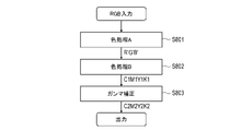
図8は、本実施形態の画像記録装置における画像処理を示すフローチャートである。ステップS801において、ディジタルカメラやスキャナなどの画像入力機器、あるいは、コンピュータ処理などによって得られたRGBの原画像信号が、色処理AによりR’G’B’信号に変換される。本実施形態において、多値画像データの入力解像度は600dpi×600dpiであり、1画素につき8bit256階調で表現される輝度データ(R,G,B)である。色処理Aは、原画像信号RGBを記録装置の色再現範囲に適応した画像信号R’G’B’へ変換する処理である。
ステップS802において、R’G’B’信号は、色処理部Bにより各色インクに対応する信号に変換される。ここでは、各インク色の多値出力データを600dpi×600dpi解像度の1画素につき、12bit4096諧調で表現されるデータに変換する。ここでは、変換後の信号はシアン、マゼンタ、イエロー、ブラックの4色にそれぞれ対応する濃度信号C1、M1、Y1、K1である。この色処理Bでは、R、G、B入力、C、M、Y、K出力の三次元ルックアップテーブル(3D LUT)を使用して出力値が求められるが、格子点から外れる入力値については、その周囲の格子点の出力値を用いた補間演算が行われる。
ステップS803において、濃度信号C1、M1、Y1、K1に対して補正テーブルを用いてガンマ補正を行い、C2、M2、Y2、K2を得る。ここでは、各色600dpi×600dpi解像度の12bitデータから、8bit256諧調データに変換される。
このようなステップS801~ステップS803の画像処理フローにより、各インク色に対応する記録データが生成される。
図6に戻り、ステップS609において、ステップS608にて展開されたプリントバッファのデータを解析し、記録素子の駆動回数HDnumをカウントする。本実施形態では、CMYK4色分の駆動回数を合算した値を、駆動回数HDnumとして扱う。
ステップS610において、ステップS609で算出した駆動回数HDnumとステップS606で求めた駆動回数閾値HDth_envとを比較し、駆動回数閾値HDth_env以上かどうかを判定する。駆動回数閾値HDth_env以上であると判定された場合はステップS611へと進み、駆動回数閾値HDth_env未満であると判定された場合はステップS613へと進む。
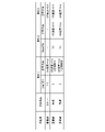
ステップS611において、記録方法を決定する。駆動回数HDnumが駆動回数閾値HDth_env以上であるため、単位時間あたりの消費電力を低減させる必要がある。図9は、記録方法を設定するための表である。図9に示す設定表では、用紙種や記録品位といった記録モードに応じた記録方法が設定されている。ここで設定される記録方法は、ステップS613へ進んだ場合、すなわち駆動回数閾値未満の場合に実行される記録方法と比較して、単位時間あたりの消費電力が低い記録方法である。
閾値比率DownTh1は、駆動回数閾値HDth_envに対する比率を示している。駆動回数閾値HDth_envと閾値比率とを乗算し、乗算値と駆動回数HDnumと比較する。本実施形態では、閾値比率として複数の値を用いて比較する。これにより、駆動回数閾値HDth_envに対する駆動回数HDnumのおおよその比率が推定でき、適切な記録方法を決定することができる。
図10は、閾値比率を用いて記録方法を決定する処理を示すフローチャートである。ステップS1001において、ステップS602にて取得した記録モードの情報を取得する。ステップS1002において、取得した記録モードに基づき、図9の表から条件1の閾値比率DownTh1と条件2の閾値比率DownTh2の値を取得する。
ステップS1003において、駆動回数閾値HDth_envと条件1の閾値比率DownTh1の値との乗算値を算出し、駆動回数HDnumの値が、この乗算値よりも大きいかどうかを判定する。例えば、普通紙・標準モードにおける閾値比率DownTh1の値は2である。従って、この判定では、駆動回数HDnumの値が、駆動回数閾値HDth_envの2倍よりも大きいかどうかが判定される。Yesの場合、すなわち2倍よりも大きい場合は、ステップS1004に進み、Noの場合、すなわち2倍以下の場合はステップS1005に進む。
ステップS1004において、図9の表から、条件1に対応する記録方法を取得する。ステップS1003において、駆動回数HDnumの値が駆動回数閾値HDth_envの2倍よりも大きい(条件1)と判定されているため、記録方法は、閾値未満だった場合に比べて、単位時間あたりの消費電力を半分以下にする必要がある。そのため、スキャン時のキャリッジ速度が標準速度の0.6倍、且つ、次のスキャンの記録データを2分割で記録する記録方法が設定される。
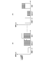
ここで、図11A及び図11Bを用いて、2分割で記録する方法について説明する。本図において、横方向は記録ヘッド9の走査方向(Y方向)であり、縦方向が記録素子の配列する方向(X方向)である。ここでは1スキャンで記録される画像を示しており、縦方向の長さは、記録ヘッド9が1回のスキャンで記録できる長さ、すなわち、記録素子が配列する幅に対応する。尚、本図では、記録ヘッドの記録素子列を1列のみ示している。
図11Aは、分割せずに記録する場合であり、記録ヘッドに配列する全ての記録素子を用いて1回のスキャンで記録された画像を示している。図11Bは、2分割して2回のスキャンで記録された画像を示している。記録ヘッド9に配列する512個の記録素子を上半分と下半分に分割し、1スキャン目で上半分の1~256番目の記録素子を用いて記録し、2スキャン目で下半分の257~512番目の記録素子を用いて記録する。このように、1スキャンでインク滴を吐出する記録素子の数を制限することにより、記録ヘッド9において単位時間あたりに消費される電力量を抑制することができる。尚、分割する方法としては、マスクパターンを用いて記録データを間引く方法等を用いてもよい。
図10に戻り、ステップS1003において条件1に該当しなかった場合、すなわち、駆動回数HDnumの値が駆動回数閾値HDth_envの2倍よりも小さいと判定された場合、ステップS1005に進む。ステップS1005では、駆動回数閾値HDth_envと条件2の閾値比率DownTh2の値との乗算値を算出し、駆動回数HDnumの値が、この乗算値よりも大きいかどうかを判定する。普通紙・標準モードにおける閾値比率DownTh2の値は1.5である。従って、この判定では、駆動回数HDnumの値が、駆動回数閾値HDth_envの1.5倍よりも大きいかどうかが判定される。大きい場合はステップS1006に進み、小さい場合はステップS1007に進む。
ステップS1006において、図9の表から、条件2に対応する記録方法を取得する。ステップ1005において、駆動回数HDnumの値が駆動回数閾値HDth_envの1.5倍よりも大きく2倍よりも小さい(条件2)と判定されているため、記録方法は、閾値未満だった場合に比べて、単位時間あたりの消費電力を2/3以下にする必要がある。そのため、スキャン時のキャリッジ速度が標準速度の0.6倍の記録方法が設定される。
条件1と条件2のいずれにも該当しなかった場合は、ステップS1007に進み、条件3の記録方法を取得する。ステップS1005において、駆動回数HDnumの値が駆動回数閾値HDth_envよりも大きく1.5倍よりも小さい(条件3)と判定されているため、スキャン時のキャリッジ速度を0.8倍にする記録方法が設定される。
このように、ステップS611において、駆動回数閾値HDth_envに対する駆動回数HDnumの比率に応じて、記録条件が設定される。このとき、駆動回数HDnumが駆動回数閾値HDth_envよりも大きい場合には、駆動回数閾値HDth_envよりも小さい場合に比べて、単位時間当たりの消費電力量の小さい記録条件が設定される。これにより、予め定められた消費電力量の範囲内で画像を記録することができる。
尚、記録方法の設定方法については、本実施形態の設定方法に限られない。例えば、基準値に対して駆動回数HDnumの値の比率を算出し、その逆数に基づいてキャリッジ速度を変更することにより、消費電力量を抑えることができる。また、記録データの分割数を3分割や4分割に増やしてもよい。尚、普通紙のきれいモードのように条件2が定義されていないような形態であってもよい。この場合、ステップS1005の判断分岐を行うことなく、ステップS1007に進み、記録方法を設定する。
図6に戻り、ステップS612において、プリントバッファのデータを再生成する。ステップS611において分割記録の記録方法が設定された場合は、分割記録に対応した記録データをプリントバッファに生成する。本実施形態では、分割数=2であり、図11A及び図11Bで説明したように1スキャン分のデータを2分割して2スキャン分の記録データを生成する。
ステップS613において、プリントバッファ上の記録データに基づいて、記録媒体上に画像を記録する。ステップS612にて分割されたデータが再生成された場合は、分割数Nに対応したNスキャン分の記録データに基づいてN回のスキャンで画像を記録する。また、ステップS611にて設定された記録方法において、キャリッジ速度を変更することが設定されている場合には、設定された記録条件に基づいてキャリッジユニット2を制御する。
ステップS614にて、記録が終了したかどうかを判定する。記録が終了しておらず、まだ記録データが残っている場合は、ステップS608に戻り、1スキャン分の記録データから生成を行い、記録処理を続ける。
以上の処理により、環境温度に応じて記録ヘッドでインクの吐出に使用できる単位時間当たりの電力量を設定することができる。このような構成により、サブヒータで記録ヘッドを保温するために使用される電力と記録ヘッドでインク吐出のために使用される電力を効率的に分配することができ、スループット低下を抑えつつ、ユーザビリティ向上に貢献することが出来る。
尚、本実施井形態の制御は、記録素子に電力を供給する電源とサブヒータに電力を供給する電源を一つの電源容量として扱う場合に、特に効果的である。これは、基板や配線、電源などの電気部品においては、瞬間的な印加電流量や平均的な印加電流量を所定の閾値以下に抑える制御が要求されるためである。一方、記録素子用の電源とサブヒータ用の電源が別構成であった場合であっても、画像記録装置の通常稼働時の最大電力量等において電力量の抑制が求められる場合がある。そのような場合においても、本実施形態の構成を適用することが可能である。例えば、記録ヘッドの保温のためのサブヒータを備えていない形態であってもよい。記録ヘッドの保温制御は、サブヒータを用いる形態の場合以外にも、電気熱変換素子である記録素子にインク滴が吐出しない程度のパルスを印加することによっても行うことができる。このような形態であっても、環境温度によって記録ヘッドの保温のために使用可能な電力量が異なるという前提は同じであるため、本実施形態の上記構成を適用することによって同様の効果を得ることができる。
尚、本実施形態の記録ヘッドにおいて、記録素子基板10の外周を取り囲むようにサブヒータが配置されているが、このような形態に限られず、記録素子列に沿って配線する等様々なレイアウトが考えられる。
尚、本実施形態では、図7Bの環境温度に応じた閾値比率パラメータ表に記された閾値比率HDhRatioは、記録モードによらず環境温度だけで変更したが、他の要因を考慮して変更してもよい。例えば、複数の記録モードのキャリッジ速度は同一ではないため、各記録モードに設定されたキャリッジ速度を考慮して閾値比率HDhRatioを設定してもよい。また、モノクロモードやカラーモードのように、記録モードによって用いられるインクの種類やインク数が異なる場合もあるため、閾値比率パラメータ表を記録モードごとに持つように拡張し、使用する記録モードごとの値を使用してもよい。
さらに、近年の画像記録装置では、インクの循環機構を有する装置や、さらにはインクの温調装置を備える装置も考えられる。そのような装置においては、記録ヘッドに流入するインク温度を取得し、環境温度として判定に用いる形態であってもよい。また、記録動作が一定時間以上行われていない場合においては、記録ヘッド9の温度は、記録装置の設置環境における温度と略等しいと考えられる。従って、このような条件下においては、温度センサS6~S9によって取得された温度を、本実施形態の環境温度として用いてもよい。この場合には、スキャン毎に環境温度を取得するのではなく、記録動作の開始前に取得された温度を環境温度として使用し続けることが好ましい。
また、本実施形態において図6のステップS609では、256階調の多値データに基づいて記録素子の駆動回数HDnumをカウントしたが、この形態に限られない。256階調の多値データを量子化処理することにより、実際に記録素子からのインクの吐出または非吐出を示す量子化データが生成されるが、この量子化データに基づいて駆動回数HDnumをカウントする形態であっても構わない。また、記録素子の駆動回数をカウントする形態に限られず、ドットカウント値を取得して閾値と比較する形態であってもよく、インク色毎の付与量を示すデータから得られる値を閾値と比較する形態であってもよい。
尚、本実施形態の画像記録装置のようにシリアル記録方式の記録装置に限定されず、固定された記録ヘッドに対して記録媒体が搬送される、所謂フルマルチ方式の画像記録装置においても適用可能である。フルマルチ方式の場合、1つの記録ヘッドに対してインク色が複数色の形態であってもよく、インク色毎に記録ヘッドを備える形態であってもよい。また、本実施形態では、毎スキャン記録素子の駆動回数をカウントし記録方法を決定したが、例えばカット紙であればページ単位、ロール紙であれば、所定の単位の区切りに基づいて記録素子の駆動回数をカウントし、記録方法を決定してもよい。フルマルチ方式の画像処理装置においては、記録媒体の搬送速度を遅くすることにより、単位時間あたりの消費電力を抑えることができる。
また、本実施形態では、インクの吐出に用いられる電力量の他に必要な電力として、記録ヘッドの保温に用いられる電力量について説明したが、他の構成についての電力を考慮した構成であってもよい。近年の多用途に対応するため、定着機構を備える画像記録装置の場合には、保温のためのサブヒータと同様に、定着機構の電力量を加味して、HD_Ratio等のパラメータを設定すればよい。また、そのような製品形態においては、定着期の定着温度を設定可能な装置が一般的である。その用途に対応すべく、定着期の設定温度を加味するようなHD_Ratioを設定することができる。
(第2の実施形態)
前述の実施形態では、1スキャン分の記録素子の駆動回数の合計値に基づいて、分割記録及びキャリッジ速度の低下によって単位時間当たりの使用電力量を抑制する制御を採用した。一方、記録素子の種類によっては、1スキャンにかかる時間での電力量よりもさらに短い時間の瞬間的な電流を考慮する必要がある場合がある。そのような場合、1スキャン分の記録データの駆動回数の合計値だけでなく、1スキャンの領域をさらに狭い領域に分割し、各領域の駆動回数に基づいて単位時間当たりの電力量の制御が求められる。本実施形態では、1スキャン領域よりも小さな分割領域での瞬間電流を考慮した駆動制御について説明する。
前述の実施形態では、1スキャン分の記録素子の駆動回数の合計値に基づいて、分割記録及びキャリッジ速度の低下によって単位時間当たりの使用電力量を抑制する制御を採用した。一方、記録素子の種類によっては、1スキャンにかかる時間での電力量よりもさらに短い時間の瞬間的な電流を考慮する必要がある場合がある。そのような場合、1スキャン分の記録データの駆動回数の合計値だけでなく、1スキャンの領域をさらに狭い領域に分割し、各領域の駆動回数に基づいて単位時間当たりの電力量の制御が求められる。本実施形態では、1スキャン領域よりも小さな分割領域での瞬間電流を考慮した駆動制御について説明する。
図12は、本実施形態の記録制御の各工程を説明するためのフローチャートである。第1の実施形態の図6の工程と重複する点については説明を省略する。
ステップS1201及びステップS1202の処理は、ステップS601及びステップS602と同一のため、説明を省略する。
ステップS1203において、ステップS1202にて取得された記録モードに対応する駆動回数閾値HDth、及び、小さな分割領域での駆動回数閾値HDth_narrowを取得する。図13Aは、図7Aと同様に、各記録モードに対応する駆動回数閾値HDthが設定された表であり、さらに分割領域の駆動回数との比較に用いる閾値HDth_narrowの値が追加されている。図13Bは、図7Bと同一であるため、説明を省略する。ここでは、普通紙・標準モードが設定された場合を例に挙げて説明する。普通紙・標準モードに対応する駆動回数閾値として、1スキャン用閾値HDth=115200、分割領域用閾値HDth_narrow=57600が取得される。
ステップS1204及びステップS1205は、ステップS605及びステップS605と同様の処理であるため、説明を省略する。
ステップS1206において、環境温度に応じた駆動回数閾値HDth_envと、分割領域用閾値HDth_env_narrowの2つの値を算出する。算出方法はステップS606と同様であり、HDth、HDth_narrowにそれぞれHDthRatioを乗算する。
ステップS1207からステップS1209は、ステップS607からステップS609と同様の処理であるため、説明を省略する。
ステップS1210において、分割領域における記録素子の駆動回数をカウントする。ステップS1209では、1スキャン分の記録データに基づいて記録素子の駆動回数をカウントしたが、ここでは各分割領域について記録素子の駆動回数をカウントし、そのカウントの最大値を分割領域での駆動回数HDnum_narrowとする。
図14A、図14B及び図14Cは、あるインク色の1スキャン分のプリントバッファを示すイメージ図である。本実施形態において、記録素子数Aは512ノズルであり、スキャン幅Bは10inch×600dpi=6000のメモリ領域である。図14Aは1スキャン全体、図14Bは分割領域の1回目の駆動回数のカウント、図14Cは分割領域の2回目の駆動回数のカウントについて図示したものである。分割領域の記録素子配列方向の幅は、512ノズルであり、1スキャンの領域と同じである。
ステップS1209において、まず、図14Aで示す1スキャン分の領域の駆動回数をカウントする。次に、図14Bに破線で記された分割領域の駆動回数をカウントする。次に、図14Cに破線で記された分割領域の駆動回数をカウントする。図14B及び図14Cに示すように、1回目にカウントされる分割領域と2回目にカウントされる分割領域は、一部が重なるように設定されている。このように分割領域をずらしながら駆動回数をカウントし、ある1回のスキャン領域における最大値を算出する。この最大値が、分割領域での駆動回数HDnum_narrowとして決定される。ここでは1色分のプリントバッファについて記しているが、実際には、CMYK4色分のプリントバッファを同時に展開し、4色分の合算値にてHDnum_narrowを決定してもよい。4色分合算する場合、記録媒体上では同一画素であっても、記録素子列が物理的にずれているため、絶対的な時間軸において吐出タイミングは同一ではなく、多少のずれが生じる。このずれを考慮して、例えば、記録素子列間の距離に基づき、吐出タイミングのずれ量を加味して合算値を求めるようにするとより好適な形態が実現可能となる。
ステップS1211において、駆動回数が閾値以上かどうかを判定する。具体的には、1スキャン領域の駆動回数HDnumが1スキャン領域の駆動回数閾値HDth_env以上かどうかの判定と、分割領域の駆動回数HDnum_narrowが分割領域の駆動回数閾値HDth_env_narrow以上かどうかを判定する。閾値以上であると判定された場合は、ステップS1212へ進み、閾値よりも小さいと判定された場合は、ステップS1214へと進む。
ステップS1212において、記録方法を決定する。この決定方法はステップS611へと同様である。ステップS611における処理を、分割領域の駆動回数HDnum_narrowについても同様に行う。1スキャンの駆動回数HDnumと、分割領域の駆動回数HDnum_narrowのそれぞれで判定した記録方法の条件が異なった場合には、条件番号が小さな方を選択すればよい。例えば、HDnumで求めた記録方法が条件2、HDnum_narrowで求めた記録方法が条件1である場合には、条件1の記録方法を選択するものとする。
以降、ステップS1213からステップS1215の処理は、ステップS612からステップS614の処理と同様の処理であるため、説明を省略する。
このように、1スキャン領域よりも小さい分割領域に対しても、記録素子の駆動回数をカウントし、閾値と比較することにより、瞬間的な短時間での耐圧性能が弱い電気素子を用いる場合においてもスループットの低下を抑制することができる。
なお、本実施形態では、1スキャン領域と分割領域とで同じ記録方法を選択する構成について説明したが、同一でなくてもよい。記録方法を個別に設定する形態であってもよい。また、上記実施形態では、1スキャン領域と分割領域のそれぞれについて閾値と比較して記録方法を決定したが、分割領域についての比較のみによって記録方法を決定する形態であってもよい。また、分割領域のサイズは上記例に限られず、X方向の幅は1スキャンの幅より短くてもよい。
本発明は上記実施の形態に制限されるものではなく、本発明の精神及び範囲から離脱することなく、様々な変更及び変形が可能である。従って、本発明の範囲を公にするために以下の請求項を添付する。
本願は、2021年3月12日提出の日本国特許出願特願2021-040473を基礎として優先権を主張するものであり、その記載内容の全てをここに援用する。
Claims (17)
- 記録媒体上にインク滴を付与することにより画像を記録する記録装置であって、
前記記録装置の設置環境における温度を取得する取得手段と、
電気エネルギーが印加されることによって駆動される複数の記録素子を備える記録ヘッドと、
前記記録ヘッドと記録媒体とを相対走査させる走査手段と、
記録の指示に応じて、前記取得手段により取得された温度に対応する閾値を設定する設定手段と、
前記記録の指示に基づき、1回の相対走査において所定の領域にインク滴を付与するための前記複数の記録素子の駆動に関する値を算出する算出手段と、
前記設定手段により設定された前記閾値と、前記算出手段により算出された前記駆動に関する値と、に基づき、画像を記録するための記録条件を決定する決定手段と、
前記決定手段により決定された前記記録条件に基づき、前記記録ヘッド及び前記走査手段を制御する制御手段と、
を備えることを特徴とする記録装置。 - 前記設定手段は、前記取得手段により取得された温度が第1の温度である場合、第1の閾値を設定し、前記取得手段により取得された温度が前記第1の温度よりも高い第2の温度である場合、前記第1の閾値よりも大きい第2の閾値を設定することを特徴とする請求項1に記載の記録装置。
- 前記決定手段は、(i)前記駆動に関する値が前記設定手段により設定された閾値よりも小さい場合、前記複数の記録素子からインク滴を吐出するために単位時間あたりに使用可能な電力量が第1の量である第1の記録条件に決定し、(ii)前記駆動に関する値が前記設定手段により設定された閾値よりも大きい場合、前記複数の記録素子からインク滴を吐出するために単位時間あたりに使用可能な電力量が前記第1の量よりも少ない第2の量である第2の記録条件に決定することを特徴とする請求項1または2に記載の記録装置。
- 前記第2の記録条件における相対走査の速度は、前記第1の記録条件における相対走査の速度よりも遅いことを特徴とする請求項3に記載の記録装置。
- 前記第2の記録条件において前記所定の領域にインク滴を付与するための相対走査の回数は、前記第1の記録条件において前記所定の領域にインク滴を付与するための相対走査の回数よりも多いことを特徴とする請求項3または4に記載の記録装置。
- 前記算出手段により算出される前記駆動に関する値は、前記複数の記録素子を駆動する駆動回数、ドットカウント値、インク色毎の付与量を示すデータから得られる値のいずれかであることを特徴とする請求項1から5のいずれか1項に記載の記録装置。
- 前記記録ヘッドを加熱するためのヒータをさらに備えることを特徴とする請求項1から6のいずれか1項に記載の記録装置。
- 前記複数の記録素子に電力を供給するための電源と、前記ヒータに電力を供給するための電源と、が共通の構成であることを特徴とする、請求項7に記載の記録装置。
- 前記設定手段は、前記取得手段により取得された温度が前記第2の温度よりも高い第3の温度である場合、前記第2の閾値よりも大きい第3の閾値を設定することを特徴とする請求項2に記載の記録装置。
- 前記設定手段は、前記取得手段により取得された温度に対応する前記所定の領域よりも小さいサイズの第2の領域に対応する閾値をさらに設定し、
前記算出手段は、前記所定の領域よりも小さいサイズの第2の領域にインク滴を付与するための前記複数の記録素子の駆動に関する第2の値をさらに算出し、
前記決定手段は、前記第2の領域に対応する閾値と、前記駆動に関する第2の値と、にさらに基づき、前記記録条件を決定することを特徴とする請求項1から9のいずれか1項に記載の記録装置。 - 前記記録ヘッドは、複数色のインクに対応する複数の記録素子列を備え、
前記算出手段により算出される駆動に関する値は、前記複数色のインクの合計値であることを特徴とする請求項1から10のいずれか1項に記載の記録装置。 - 第1の方向に前記複数の記録素子が配列し、前記第1の方向と交差する第2の方向に前記走査手段による相対走査が行われることを特徴とする請求項1から11のいずれか1項に記載の記録装置。
- 前記第1の方向に記録媒体を搬送する搬送手段をさらに備え、
前記走査手段は、前記第2の方向に前記記録ヘッドを走査させることを特徴とする請求項12に記載の記録装置。 - 電気エネルギーが印加されることによって駆動される複数の記録素子を備える記録ヘッドと、前記記録ヘッドと記録媒体とを相対走査させる走査手段と、を備える記録装置のための制御方法であって、
前記記録装置の設置環境における温度を取得する取得工程と、
記録の指示に応じて、取得された温度に対応する閾値を設定する設定工程と、
前記記録の指示に基づき、1回の相対走査において所定の領域にインク滴を付与するために前記複数の記録素子の駆動に関する値を算出する算出工程と、
設定された前記閾値と、算出された前記駆動に関する値と、に基づき、画像を記録するための記録条件を決定する決定工程と、
決定された前記記録条件に基づき、前記記録ヘッド及び前記走査手段を制御する制御工程と、
を備えることを特徴とする制御方法。 - 記録媒体上にインク滴を付与することにより画像を記録する記録装置であって、
前記記録装置の設置環境における温度を取得する取得手段と、
電気エネルギーを用いてインク滴を吐出する複数の記録素子を備える記録ヘッドと、
前記記録ヘッドと記録媒体とを相対走査させる走査手段と、
記録データ及び前記取得手段により取得された温度に基づいて設定された記録条件に基づいて、前記記録ヘッド及び前記走査手段による記録動作を制御する制御手段と、
を備え、
前記制御手段は、前記取得手段により取得された温度が第1の温度である場合、前記複数の記録素子からインク滴を吐出するために単位時間あたりに使用可能な電力量が第1の量である第1の記録条件を設定し、前記取得手段により取得された温度が前記第1の温度よりも高い第2の温度である場合、前記複数の記録素子からインク滴を吐出するために単位時間あたりに使用可能な電力量が前記第1の量よりも多い第2の量であるである第2の記録条件を設定することを特徴とする記録装置。 - 電気エネルギーを用いてインク滴を吐出する複数の記録素子を備える記録ヘッドと、前記記録ヘッドと記録媒体とを相対走査させる走査手段と、を備える記録装置のための制御方法であって、
前記記録装置の設置環境における温度を取得する取得工程と、
記録データ及び取得された温度に基づいて設定された記録条件に基づき、前記記録ヘッド及び前記走査手段による記録動作を制御する制御工程と、
を備え、
取得された温度が第1の温度である場合、前記複数の記録素子からインク滴を吐出するために単位時間あたりに使用可能な電力量が第1の量である第1の記録条件が設定され、取得された温度が前記第1の温度よりも高い第2の温度である場合、前記複数の記録素子からインク滴を吐出するために単位時間あたりに使用可能な電力量が前記第1の量よりも多い第2の量であるである第2の記録条件が設定されることを特徴とする制御方法。 - 請求項14または請求項16の制御方法に記載の各工程をコンピュータに実行させるためのプログラム。
Priority Applications (1)
| Application Number | Priority Date | Filing Date | Title |
|---|---|---|---|
| US18/464,990 US20230415474A1 (en) | 2021-03-12 | 2023-09-11 | Recording apparatus, control method, and program |
Applications Claiming Priority (2)
| Application Number | Priority Date | Filing Date | Title |
|---|---|---|---|
| JP2021040473A JP7693339B2 (ja) | 2021-03-12 | 2021-03-12 | 記録装置、制御方法及びプログラム |
| JP2021-040473 | 2021-03-12 |
Related Child Applications (1)
| Application Number | Title | Priority Date | Filing Date |
|---|---|---|---|
| US18/464,990 Continuation US20230415474A1 (en) | 2021-03-12 | 2023-09-11 | Recording apparatus, control method, and program |
Publications (1)
| Publication Number | Publication Date |
|---|---|
| WO2022190983A1 true WO2022190983A1 (ja) | 2022-09-15 |
Family
ID=83227200
Family Applications (1)
| Application Number | Title | Priority Date | Filing Date |
|---|---|---|---|
| PCT/JP2022/008827 Ceased WO2022190983A1 (ja) | 2021-03-12 | 2022-03-02 | 記録装置、制御方法及びプログラム |
Country Status (3)
| Country | Link |
|---|---|
| US (1) | US20230415474A1 (ja) |
| JP (1) | JP7693339B2 (ja) |
| WO (1) | WO2022190983A1 (ja) |
Citations (6)
| Publication number | Priority date | Publication date | Assignee | Title |
|---|---|---|---|---|
| US6154229A (en) * | 1997-10-28 | 2000-11-28 | Hewlett-Packard Company | Thermal ink jet print head and printer temperature control apparatus and method |
| JP2005035080A (ja) * | 2003-07-17 | 2005-02-10 | Fuji Xerox Co Ltd | 記録ヘッド及び記録装置 |
| JP2005246641A (ja) * | 2004-03-01 | 2005-09-15 | Canon Inc | 記録装置及びその制御方法、プログラム |
| JP2011230302A (ja) * | 2010-04-23 | 2011-11-17 | Canon Inc | インクジェット記録装置 |
| JP2019006041A (ja) * | 2017-06-27 | 2019-01-17 | キヤノン株式会社 | 記録装置および記録方法 |
| JP2019177608A (ja) * | 2018-03-30 | 2019-10-17 | キヤノン株式会社 | 画像形成装置および画像形成装置の制御方法 |
Family Cites Families (10)
| Publication number | Priority date | Publication date | Assignee | Title |
|---|---|---|---|---|
| JP4045723B2 (ja) | 2000-07-19 | 2008-02-13 | ブラザー工業株式会社 | 画像形成装置 |
| JP3988122B2 (ja) * | 2001-03-28 | 2007-10-10 | セイコーエプソン株式会社 | 印刷装置、印刷ヘッド機構の制御装置及び方法 |
| US6843548B2 (en) * | 2002-01-11 | 2005-01-18 | Konica Corporation | Ink-jet printer |
| US7040731B2 (en) | 2004-01-26 | 2006-05-09 | Benq Corporation | Method of adjusting the velocity of a printhead carriage according to the temperature of the printhead |
| JP4375401B2 (ja) * | 2004-08-06 | 2009-12-02 | コニカミノルタエムジー株式会社 | インクジェット記録装置 |
| JP2009056669A (ja) | 2007-08-31 | 2009-03-19 | Seiko Epson Corp | ヘッド駆動回路の温度検出装置、画像形成装置及びヘッド駆動回路の温度検出方法 |
| JP2015217632A (ja) | 2014-05-20 | 2015-12-07 | キヤノン株式会社 | インクジェット記録装置およびインクジェット記録方法 |
| JP6812652B2 (ja) | 2016-03-31 | 2021-01-13 | ブラザー工業株式会社 | 液体吐出装置 |
| JP6965017B2 (ja) | 2016-05-30 | 2021-11-10 | キヤノン株式会社 | 記録素子基板および記録装置 |
| JP6895717B2 (ja) * | 2016-06-01 | 2021-06-30 | キヤノン株式会社 | 素子基板および記録装置 |
-
2021
- 2021-03-12 JP JP2021040473A patent/JP7693339B2/ja active Active
-
2022
- 2022-03-02 WO PCT/JP2022/008827 patent/WO2022190983A1/ja not_active Ceased
-
2023
- 2023-09-11 US US18/464,990 patent/US20230415474A1/en active Pending
Patent Citations (6)
| Publication number | Priority date | Publication date | Assignee | Title |
|---|---|---|---|---|
| US6154229A (en) * | 1997-10-28 | 2000-11-28 | Hewlett-Packard Company | Thermal ink jet print head and printer temperature control apparatus and method |
| JP2005035080A (ja) * | 2003-07-17 | 2005-02-10 | Fuji Xerox Co Ltd | 記録ヘッド及び記録装置 |
| JP2005246641A (ja) * | 2004-03-01 | 2005-09-15 | Canon Inc | 記録装置及びその制御方法、プログラム |
| JP2011230302A (ja) * | 2010-04-23 | 2011-11-17 | Canon Inc | インクジェット記録装置 |
| JP2019006041A (ja) * | 2017-06-27 | 2019-01-17 | キヤノン株式会社 | 記録装置および記録方法 |
| JP2019177608A (ja) * | 2018-03-30 | 2019-10-17 | キヤノン株式会社 | 画像形成装置および画像形成装置の制御方法 |
Also Published As
| Publication number | Publication date |
|---|---|
| JP2022139899A (ja) | 2022-09-26 |
| US20230415474A1 (en) | 2023-12-28 |
| JP7693339B2 (ja) | 2025-06-17 |
Similar Documents
| Publication | Publication Date | Title |
|---|---|---|
| US5847724A (en) | Method for diffusing errors according to spot size in a printed liquid ink image | |
| US20110075174A1 (en) | Image processing apparatus and image processing method | |
| JP5517833B2 (ja) | 画像処理装置および画像処理方法 | |
| JPH1044519A (ja) | 画像記録装置および画像記録システム | |
| JPH1044391A (ja) | 画像記録装置 | |
| JP2005001337A (ja) | インクジェット記録装置 | |
| JP2022006642A (ja) | 記録装置、制御方法、記憶媒体及びプログラム | |
| JP2018149690A (ja) | 画像処理装置、画像処理プログラム、及び、印刷装置 | |
| JP4497807B2 (ja) | 記録装置および該装置の制御方法 | |
| US20110304666A1 (en) | Inkjet printing apparatus and inkjet printing method | |
| JP3996857B2 (ja) | インクジェットプリンタ,及びインクジェットプリントシステム | |
| JP6039442B2 (ja) | 記録制御装置、記録制御方法および記憶媒体 | |
| US20100156979A1 (en) | Inkjet printing apparatus and printing method | |
| JP3541668B2 (ja) | 印刷装置および印刷方法並びに記録媒体 | |
| JP7693339B2 (ja) | 記録装置、制御方法及びプログラム | |
| JP3184744B2 (ja) | 解像度変換可能なインクジェット記録方法 | |
| JP2008162094A (ja) | 画像形成装置およびその制御方法、画像形成システム | |
| JP7811868B2 (ja) | 印刷制御装置および方法 | |
| US8619323B2 (en) | Image processing apparatus and image processing method for processing multivalued image data and recording an image in a pixel area on recording medium by a plurality of relative scans of recording head and recording medium | |
| US20040196476A1 (en) | Online bi-directional color calibration | |
| JP2009113326A (ja) | インクジェットプリンタ | |
| JP2024140695A (ja) | 制御装置、インクジェット記録装置、方法、及びプログラム | |
| JP7790922B2 (ja) | 記録装置及び制御方法 | |
| JP2005014488A (ja) | 改善インクの吐出制御 | |
| JP4300742B2 (ja) | 画像データの階調数を変換する画像処理装置 |
Legal Events
| Date | Code | Title | Description |
|---|---|---|---|
| 121 | Ep: the epo has been informed by wipo that ep was designated in this application |
Ref document number: 22766942 Country of ref document: EP Kind code of ref document: A1 |
|
| NENP | Non-entry into the national phase |
Ref country code: DE |
|
| 122 | Ep: pct application non-entry in european phase |
Ref document number: 22766942 Country of ref document: EP Kind code of ref document: A1 |