WO2022190875A1 - ブラケット - Google Patents
ブラケット Download PDFInfo
- Publication number
- WO2022190875A1 WO2022190875A1 PCT/JP2022/007519 JP2022007519W WO2022190875A1 WO 2022190875 A1 WO2022190875 A1 WO 2022190875A1 JP 2022007519 W JP2022007519 W JP 2022007519W WO 2022190875 A1 WO2022190875 A1 WO 2022190875A1
- Authority
- WO
- WIPO (PCT)
- Prior art keywords
- panel
- bracket
- wire harness
- contact
- attached
- Prior art date
- Legal status (The legal status is an assumption and is not a legal conclusion. Google has not performed a legal analysis and makes no representation as to the accuracy of the status listed.)
- Ceased
Links
Images




Classifications
-
- B—PERFORMING OPERATIONS; TRANSPORTING
- B60—VEHICLES IN GENERAL
- B60R—VEHICLES, VEHICLE FITTINGS, OR VEHICLE PARTS, NOT OTHERWISE PROVIDED FOR
- B60R16/00—Electric or fluid circuits specially adapted for vehicles and not otherwise provided for; Arrangement of elements of electric or fluid circuits specially adapted for vehicles and not otherwise provided for
- B60R16/02—Electric or fluid circuits specially adapted for vehicles and not otherwise provided for; Arrangement of elements of electric or fluid circuits specially adapted for vehicles and not otherwise provided for electric constitutive elements
- B60R16/0207—Wire harnesses
- B60R16/0215—Protecting, fastening and routing means therefor
-
- B—PERFORMING OPERATIONS; TRANSPORTING
- B60—VEHICLES IN GENERAL
- B60R—VEHICLES, VEHICLE FITTINGS, OR VEHICLE PARTS, NOT OTHERWISE PROVIDED FOR
- B60R16/00—Electric or fluid circuits specially adapted for vehicles and not otherwise provided for; Arrangement of elements of electric or fluid circuits specially adapted for vehicles and not otherwise provided for
- B60R16/02—Electric or fluid circuits specially adapted for vehicles and not otherwise provided for; Arrangement of elements of electric or fluid circuits specially adapted for vehicles and not otherwise provided for electric constitutive elements
-
- H—ELECTRICITY
- H02—GENERATION; CONVERSION OR DISTRIBUTION OF ELECTRIC POWER
- H02G—INSTALLATION OF ELECTRIC CABLES OR LINES, OR OF COMBINED OPTICAL AND ELECTRIC CABLES OR LINES
- H02G3/00—Installations of electric cables or lines or protective tubing therefor in or on buildings, equivalent structures or vehicles
- H02G3/30—Installations of cables or lines on walls, floors or ceilings
Definitions
- the present invention relates to a bracket that suppresses interference of wire harnesses with panels.
- Patent Document 1 Conventionally, a vehicle is equipped with a wire harness that electrically connects the on-board electrical components, but there is a concern that the wire harness may come into contact with the vehicle body panel due to vibrations when the vehicle is running.
- This countermeasure is disclosed in Patent Document 1, for example. That is, in Patent Document 1, a separation distance of a specified size or more is provided between the edge portion of the vehicle body panel and the wire bundle held by the clamp member, and the deflection width of the wire bundle during vibration is less than the specified size.
- a technique is disclosed for setting the installation interval of the clamp members so that
- Patent Document 1 is a technique for preventing contact between a wire harness and a vehicle body panel by adjusting dimensions between members. For this reason, there is a problem that it takes time and effort to set the dimension adjustment. Therefore, there is a need for technical development that can prevent contact between the wire harness and the panel with a simple configuration.
- An object of the present disclosure is to provide a bracket that can suppress interference of wire harnesses with panels with a simple configuration.
- a bracket for solving the above problem is configured to be attached to a metal panel forming at least a portion of a storage compartment, and has a first side attached to the panel and a side opposite the first side. and a second surface in contact with the wire harness to guard the panel from contact with the wire harness routed inside the storage chamber.
- FIG. 1 is a schematic diagram showing the configuration inside the engine room.
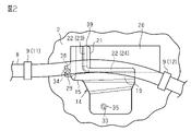
- FIG. 2 is a front view showing the wire harness in contact with the bracket.
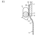
- FIG. 3 is a cross-sectional view of the wire harness and bracket.
- FIG. 4 is a perspective view of a bracket.
- FIG. 5 is a perspective view of a bracket.
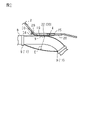
- FIG. 6 is a side view of the bracket.
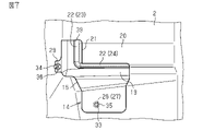
- FIG. 7 is a front view showing how the bracket is attached to the panel.
- FIG. 8 is a schematic diagram showing how the engine vibrates.
- FIG. 9 is an explanatory diagram showing the movable range of the wire harness.
- the bracket of the present disclosure is configured to be attached to a metal panel forming at least a portion of a storage compartment, and has a first side attached to said panel and a side opposite said first side. and a second surface serving as a guard surface in contact with the wire harness in order to guard the panel from contact with the wire harness routed inside the storage chamber.
- a bracket is attached to the metal panel, and the wire harness inside the storage compartment is first brought into contact with this bracket. Therefore, when vibration occurs, the wire harness is less likely to be hit against the panel, and the panel is less likely to be damaged.
- the bracket By simply attaching the bracket to the panel, it is possible to suppress interference of the wire harness with the panel. Therefore, it is possible to suppress the interference of the wire harness to the panel with a simple configuration.
- the bracket has a notch that exposes the stamping surface provided on the panel when the bracket is attached to the panel. According to this configuration, when the bracket is attached to the panel, the punched surface of the panel can be visually recognized through the notch.
- the bracket has a plurality of receiving surfaces that support the wire harness so that the wire harness traverses the notch. According to this configuration, when the notch is provided to expose the stamped surface, the wire harness can be firmly supported by a plurality of receiving surfaces, which may be end surfaces of the notch, for example.
- the receiving surface includes a first receiving surface that contacts one side surface of the wire harness and a second receiving surface that contacts another side surface of the wire harness.
- the bracket has a bracket body.
- the first receiving surface and the second receiving surface extend in the planar direction of the bracket body so as to be orthogonal to each other. According to this configuration, for example, it is possible to efficiently bring a wire harness having a wiring path extending in an oblique direction into contact with the bracket.
- the bracket is provided with a fixing portion that is fixed to the panel and is uniquely assembled to the panel. According to this configuration, when attaching the bracket to the panel, the bracket can be firmly fixed to the panel by the fixing portion.
- the bracket is provided with a tolerance-absorbing mounting portion that enables fixation to the panel while absorbing the tolerance of mounting to the panel. According to this configuration, when the bracket is attached to the panel, the attachment position is flexible, so it is possible to improve the work at the time of attachment.
- At least the second surface of the bracket is made of resin.
- the wire harness is fixed to both the vibration source arranged in the storage chamber and the frame constituting the storage chamber, and the wire harness is fixed to the vibration source at a first position. Contact is made at an intermediate position between the fixed position and the second fixed position, which is the fixed position with respect to the frame. According to this configuration, when the vibration source vibrates, even if the wire harness vibrates in conjunction with the vibration, the wire harness can be supported by the bracket. Therefore, the wire harness does not come into contact with the panel.
- the vehicle 1 has a storage room 3 with metal panels 2 as walls.
- the storage room 3 is an engine room 5 that houses a vibration source 4 (an engine 4aa in this example) in the vehicle 1 .
- the storage room 3 is arranged, for example, in the front part of the vehicle body, and is opened to the outside when the hood of the vehicle 1 is opened.
- a wire harness 8 for electrically connecting electrical components of the vehicle 1 is stored in the storage room 3 .
- the wire harness 8 includes one or more electric wires.
- the wire harness 8 is attached and fixed to the vehicle 1 via a plurality of attachments 9, for example.
- the fixture 9 includes, for example, a first fixture 11 for fixing the wire harness 8 to the engine 4 a and a second fixture 12 for fixing the wire harness 8 to the frame 10 .
- the attachment 9 can be, for example, a clip.
- the panel 2 is attached with a bracket 14 that prevents the wire harness 8 from contacting the panel 2 .
- the bracket 14 is interposed between the panel 2 and the wire harness 8 to prevent the wire harness 8 from interfering with the panel 2 even if the engine 4a or the vehicle body (frame 10) vibrates. belongs to.
- the bracket 14 can be attached to a predetermined attachment position of the panel 2 so that the wire harness 8 arranged in the storage room 3 comes into contact with (first contact with) the panel 2 .
- the frame 10 may be, for example, a vehicle body frame.
- the bracket 14 can 8 at an intermediate position 16c between the first fixed position 16a and the second fixed position 16b. That is, the wire harness 8 first hits the bracket 14 at an intermediate position 16c between the first fixing position 16a and the second fixing position 16b.
- the intermediate position 16c is not necessarily limited to the center as long as it is between the first fixed position 16a and the second fixed position 16b, and may be a position other than the center.
- the wire harness 8 first hits the bracket 14 when assembled to the vehicle 1 .
- Preliminary contact refers to, for example, a state in which the wire harness 8 is in constant contact with the bracket 14 in the assembled state.
- the bracket 14 brings the wire harness 8 into contact with the bracket body 15 .
- the wire harness 8 does not come into direct contact with the metal panel 2.
- the bracket 14 is made of resin, for example.
- the material of the bracket 14 may be polypropylene, for example.
- the coefficient of friction ⁇ of the bracket 14 is, for example, "0.3".
- the coefficient of friction ⁇ of the metal panel 2 is, for example, "0.5 to 0.6".
- the resin bracket 14 has a smaller coefficient of friction ⁇ than the metal panel 2 .
- the mounting position of the bracket 14 can be determined in advance so that the wire harness 8 first contacts the bracket 14 with a small coefficient of friction ⁇ rather than the panel 2 with a high coefficient of friction ⁇ .
- the bracket 14 has a first surface 18 attached to the panel 2 and a second surface 19 on the opposite side.
- the second surface 19 serves as a guard surface that contacts the wire harness 8 to guard the panel 2 from contact with the wire harness 8 routed inside the storage chamber 3 having the panel 2 as a side surface.
- Bracket 14 contacts panel 2 on at least a portion of first surface 18 and wire harness 8 on at least a portion of second surface 19 .
- At least the second surface 19 of the bracket 14 is preferably made of resin.
- the bracket 14 has a notch 21 that exposes the stamping surface 20 provided on the panel 2 .
- the notch portion 21 is formed by notching or thinning the bracket body 15 .
- the stamping surface 20 is a display part in which vehicle-specific information such as a vehicle body number is written, for example.
- the stamped surface 20 is preferably a portion of the panel 2 that protrudes by a predetermined amount from other portions.
- the bracket 14 has a plurality of receiving surfaces 22 that support the wire harness 8 across.
- the receiving surface 22 is, for example, a predetermined portion of the second surface 19 of the bracket body 15 that contacts the wire harness 8 .
- the receiving surface 22 includes a first receiving surface 23 that contacts one side surface of the wire harness 8 and a second receiving surface 24 that contacts another side surface of the wire harness 8 .
- the first receiving surface 23 supports a portion of the wire harness 8 closer to the first fixture 11 .
- the second receiving surface 24 supports a portion of the wire harness 8 closer to the second fixture 12 .
- the bracket 14 is formed in an approximately L-shape. That is, the first receiving surface 23 and the second receiving surface 24 extend in the plane direction of the bracket body 15 (the YZ-axis plane in FIG. 4, etc.) so as to be orthogonal to each other.
- the bracket 14 has a fixing portion 26 that serves as a fixing portion to the panel 2 .
- the fixed portion 26 is preferably, for example, a perfect circular hole 27 provided in the bracket body 15 .
- the bracket 14 is provided with a tolerance absorbing attachment portion 28 as a fixing portion other than the above-described fixing portion 26 to the panel 2 .
- the tolerance absorbing mounting portion 28 is preferably, for example, an elongated notch groove 30 formed by notching a protruding piece 29 positioned at the edge of the bracket body 15 .
- the bracket 14 is attached and fixed to the panel 2 via a fixing portion 26 and a tolerance absorbing attachment portion 28.
- a threaded shaft 33 of the panel 2 is inserted into the hole 27 and another threaded shaft 34 of the panel 2 is inserted into the slotted groove 30 .
- the bracket 14 is aligned with the panel 2 by adjusting the positional relationship between the elongated notch groove 30 and the screw shaft 34 .
- the fixing portion 26 has a structure in which the screw shaft 33 is inserted into the perfectly circular hole 27 and fixed, it can be said that the fixing portion 26 has a structure in which the attachment to the panel 2 is unique.
- the bracket 14 is fixed to the panel 2 by screwing a bolt 35 onto the tip of the screw shaft 33 and screwing a bolt 36 onto the tip of the screw shaft 34 .
- the bracket 14 has an edge portion 39 that is placed on the edge portion of the panel 2 when attached to the panel 2 .
- the edge portion 39 is provided at a position along the side of the notch portion 21 .
- the protrusion amount W (see FIG. 6) of the edge portion 39 is formed to a height corresponding to the protrusion amount of the panel 2 .
- the inner end surface or the inner edge of the edge portion 39 serves as the first receiving surface 23 and the second receiving surface 24, and the wire harness 8 hits first.
- a bracket 14 is attached to the metal panel 2 that is the wall surface of the engine room 5 , and the wire harness 8 inside the engine room 5 is brought into contact with the bracket 14 in advance. That is, the wire harness 8 in the engine room 5 is brought into contact with the bracket 14 attached to the panel 2 in advance.
- the engine 4a vibrates when it is in operation.
- the engine 4a vibrates in the direction of arrow A in the figure.
- the wire harness 8 since the wire harness 8 is attached to the engine 4a through the first attachment 11, the wire harness 8 also vibrates in conjunction with the movement of the engine 4a. If the wire harness 8 vibrates, it may contact the panel 2 .
- the wire harness 8 contacts the bracket 14 attached to the panel 2.
- the bracket 14 can reduce the maximum amplitude or the maximum movement amount E of the harness 8 as compared with the comparative example in which the bracket 14 is not attached to the panel 2 .
- contact of the wire harness 8 with the painted surface or the stamped surface 20 of the panel 2 can be prevented or reduced.
- scratches on the coated surface of the panel 2 and abrasion of the stamped surface 20 due to contact with the wire harness 8 can be prevented or reduced. Rust and corrosion of the panel 2 can be prevented or reduced.
- Bracket 14 is attached to the metal panel 2 that partitions the storage room 3 .
- Bracket 14 has a first surface 18 and a second surface 19 .
- a first surface 18 is attached to the panel 2 .
- the second surface 19 is located on the opposite side of the first surface 18 and serves as a guard surface that contacts the wire harness 8 to guard the panel 2 from contact with the wire harness 8 routed inside the storage chamber 3 .
- the bracket 14 by attaching the bracket 14 to the metal panel 2 , the wire harness 8 in the storage room 3 is brought into contact with the bracket 14 before the panel 2 . Therefore, when vibration occurs, the wire harness 8 is less likely to be hit against the panel 2, so that the panel 2 is less likely to be damaged.
- interference of the wire harness 8 with the panel 2 can be suppressed. Therefore, interference of the wire harness 8 with the panel 2 can be suppressed with a simple configuration.
- the panel 2 Since the coating peeling of the panel 2 is less likely to occur, the panel 2 is less likely to rust. (3) Since the stamping surface 20 is less likely to wear, it is possible to prevent or reduce the visibility of vehicle-specific information such as the vehicle body number on the stamping surface 20 .
- the bracket 14 has a notch 21 that exposes the stamping surface 20 provided on the panel 2 . According to this configuration, the stamped surface 20 of the panel 2 can be visually recognized through the notch 21 when the bracket 14 is attached to the panel 2 .
- the bracket 14 has a plurality of receiving surfaces 22 that support the wire harness 8 so that the wire harness 8 crosses the notch 21 . According to this configuration, when the notch 21 is provided to expose the stamping surface 20, the wire harness 8 can be firmly supported by the plurality of receiving surfaces 22, which may be the end surfaces of the notch 21, for example. .
- the receiving surface 22 includes a first receiving surface 23 that contacts one side surface of the wire harness 8 and a second receiving surface 24 that contacts another side surface of the wire harness 8 .
- the wire harness 8 can be firmly supported on two surfaces.
- the bracket 14 has a bracket body 15 .
- the first receiving surface 23 and the second receiving surface 24 extend in the plane direction of the bracket body 15 (the YZ-axis plane in FIG. 4, etc.) so as to be orthogonal to each other. According to this configuration, for example, the wire harness 8 whose routing path extends in the oblique direction can be brought into contact with the bracket 14 efficiently.
- the bracket 14 has a fixing portion 26 that is a fixing portion to the panel 2 .
- the fixing part 26 is primarily assembled to the panel 2 . According to this configuration, when attaching the bracket 14 to the panel 2 , the bracket 14 can be firmly fixed to the panel 2 by the fixing portion 26 .
- the bracket 14 is provided with a tolerance absorbing mounting portion 28 that enables fixation to the panel 2 while absorbing mounting tolerance to the panel 2 . According to this configuration, when the bracket 14 is attached to the panel 2, the mounting position is flexible, so that the mounting work can be improved.
- At least the second surface 19 of the bracket 14 is made of resin. According to this configuration, the frictional resistance of the second surface 19 of the bracket 14 can be reduced, so that the wire harness 8 in contact with the second surface 19 can be made slippery. Therefore, it is possible to prevent the wire harness 8 from hitting the second surface 19 of the bracket 14 when vibration occurs.
- the wire harness 8 is fixed to the vibration source 4 (in this example, the engine 4a) arranged in the storage room 3 and the frame 10 forming the storage room 3 .
- the bracket 14 contacts the wire harness 8 at an intermediate position 16c between a first fixing position 16a where the vibration source 4 is fixed and a second fixing position 16b where the frame 10 is fixed.
- this embodiment can be changed and implemented as follows. This embodiment and the following modified examples can be implemented in combination with each other within a technically consistent range. - The entire surface of the first surface 18 may contact the panel 2 , or only a portion of the first surface 18 may contact the panel 2 .
- the second surface 19 may be made of resin only at least at a portion where the wire harness 8 contacts.
- the notch 21 of the bracket 14 may be omitted.
- the storage room 3 is not limited to the engine room 5 and may be another room provided in the vehicle 1 .
- a plurality of brackets 14 may be provided in one vehicle 1 .
- the wire harness 8 is not limited to a structure that contacts the bracket 14 in advance, and may be formed to a dimension that contacts the bracket 14 during vibration.
- the shape of the bracket 14 is not limited to the shape having the edge portion 39 protruding by a predetermined amount.
- the 1st receiving surface 23 and the 2nd receiving surface 24 are not limited to mutually orthogonally crossing, For example, you may extend in parallel.
- the number of receiving surfaces 22 is not limited to two, and may be three or more.
- the notch 21 may be a hole.
- the method of fixing the bracket 14 to the panel 2 is not limited to the configuration using the fixing portion 26 and the tolerance absorbing mounting portion 28. For example, there are various methods such as engaging a clip-shaped projection with a recess of the panel 2. Applicable.
- - Elastically deformable rubber may be used for the second surface 19 .
- the second surface 19 is not limited to being made of resin, and may be made of metal, for example.
- a single wire harness 8 may be brought into contact with the panel 2 with a plurality of brackets 14 .
- Bracket 14 is not limited to vehicle-mounted use, and may be used for other devices and equipment. • Brackets 14 in the illustrated embodiment are sometimes referred to as panel protection patches. 21 in the illustrated embodiment may be referred to as a vehicle body information viewing window.
- a wire harness unit comprising a bracket attached to a metal panel forming a storage room and a wire harness routed inside the storage room.
- the bracket has a first surface attached to the panel and a second surface opposite the first surface and in contact with the wire harness to guard the panel from contact with the wire harness. wire harness unit.
- (Appendix 2) A routing unit comprising a metal panel forming a storage room, a bracket attached to the panel, and a wire harness routed inside the storage room, wherein the bracket A wiring unit comprising: a first surface attached to a panel; and a second surface located on the opposite side of the first surface and guarding the panel from contact with the wire harness.
- An embodiment of the present disclosure is used with a metal panel (2) having a painted surface and a wire harness (8) placed in close proximity to the painted surface of the metal panel (2), directed to a panel protection patch (14) configured to protect the painted surface of the metal panel (2), the panel protection patch (14) comprising: a fixing part (26) for retrofitting the panel protection patch (14) to a predetermined mounting position of the metal panel (2); A guard surface (19) configured to contact the wire harness (8) may be provided to guard the painted surface from repeated contact with the wire harness (8).
- the metal panel (2) may have a stamping surface (20) stamped with vehicle body information
- the panel protection patch (14) may have a vehicle body information viewing window (21) that exposes the stamped surface (20) so that the vehicle body information can be visually recognized.
- the panel protection patch (14) may be a one-piece synthetic resin product.
Landscapes
- Engineering & Computer Science (AREA)
- Mechanical Engineering (AREA)
- Architecture (AREA)
- Civil Engineering (AREA)
- Structural Engineering (AREA)
- Installation Of Indoor Wiring (AREA)
Abstract
Description
[1]本開示のブラケットは、収納室の少なくとも一部を形成する金属製のパネルに取り付けられるように構成されており、前記パネルへ取り付けられる第1面と、前記第1面とは反対側に位置し、前記収納室の内部に配策されるワイヤハーネスとの接触からパネルをガードすべく前記ワイヤハーネスと接触するガード面となる第2面とを備えている。
本開示のブラケットの具体例を、以下に図面を参照しつつ説明する。なお、本発明はこれらの例示に限定されるものではなく、特許請求の範囲によって示され、特許請求の範囲と均等の意味および範囲内でのすべての変更が含まれることが意図される。各図面では、説明の便宜上、構成の一部を誇張又は簡略化して示す場合がある。また、各部分の寸法比率についても、実際とは異なる場合がある。
図8に示すように、エンジンルーム5の壁面である金属製のパネル2にブラケット14が取り付けられ、エンジンルーム5内のワイヤハーネス8をブラケット14に先当てする。すなわち、パネル2に取り付けられたブラケット14に対し、エンジンルーム5内のワイヤハーネス8を予め接触させた状態にしておく。
(1)ブラケット14は、収納室3を区画する金属製のパネル2に取り付けられる。ブラケット14は、第1面18、及び第2面19を備えている。第1面18は、パネル2へ取り付けられる。第2面19は、第1面18とは反対側に位置し、収納室3の内部に配策されるワイヤハーネス8との接触からパネル2をガードすべくワイヤハーネス8と接触するガード面となる。
(3)打刻面20の摩耗が生じにくくなるので、打刻面20の車体番号などの車体固有情報を視認できなくなることを防止または低減できる。
・第1面18の全面がパネル2と接触してもよく、第1面18の一部のみがパネル2と接触してもよい。
・ブラケット14の切欠部21は省略してもよい。
・1台の車両1にブラケット14が複数設けられてもよい。
・ワイヤハーネス8は、ブラケット14に先当たりされる構成に限らず、振動時にブラケット14と接触する寸法に形成されてもよい。
・第1受け面23及び第2受け面24は、互いに直交することに限定されず、例えば、平行に延在してよいよい。
・切欠部21は、孔でもよい。
・パネル2へのブラケット14の固定方法は、固定部26及び公差吸収取付部28を用いた構成に限らず、例えば、クリップ状の突起をパネル2の凹部に係合するなど、種々の方法が適用できる。
・第2面19は、樹脂製に限らず、例えば、金属製としてもよい。
・1本のワイヤハーネス8に対して、複数のブラケット14でパネル2に接触させてもよい。
・図示した実施形態のブラケット14は、パネル保護パッチとして参照することがある。図示した実施形態の21は、車体情報視認用窓として参照することがある。
(付記1)収納室を形成する金属製のパネルに取り付けられるブラケットと、前記収納室の内部に配策されるワイヤハーネスとを備えるワイヤハーネスユニットであって、前記ブラケットは、前記パネルへ取り付けられる第1面と、前記第1面とは反対側に位置し、前記ワイヤハーネスと接触からパネルをガードすべくワイヤハーネスと接触する第2面とを備えるワイヤハーネスユニット。
前記パネル保護パッチ(14)を前記金属パネル(2)の所定の取付位置に後付けするための固定部(26)と、
前記ワイヤハーネス(8)との繰り返しの接触から前記塗装面をガードするために前記ワイヤハーネス(8)と接触するように構成されたガード面(19)を備えることができる。
前記パネル保護パッチ(14)は、前記車体情報が視認できるように前記打刻面(20)を露出させる車体情報視認用窓(21)を有してよい。
2 パネル
3 収納室
4 振動源
4a エンジン
5 エンジンルーム
8 ワイヤハーネス
9 取り付け具
10 フレーム
11 第1取り付け具
12 第2取り付け具
14 ブラケット(パネル保護パッチ)
15 ブラケット本体
16a 第1固定位置
16b 第2固定位置
18 第1面
19 第2面
20 打刻面
21 切欠部
22 受け面
23 第1受け面
24 第2受け面
26 固定部
27 孔
28 公差吸収取付部
29 突設片
30 長孔状切欠溝
33 ネジ軸
34 ネジ軸
35 ボルト
36 ボルト
39 縁部
μ 摩擦係数
W 突出量
E 最大振幅
Claims (9)
- 収納室の少なくとも一部を形成する金属製のパネルに取り付けられるブラケットであって、
前記パネルへ取り付けられる第1面と、
前記第1面とは反対側に位置し、前記収納室の内部に配策されるワイヤハーネスとの接触から前記パネルをガードすべく前記ワイヤハーネスと接触する第2面と
を備えるブラケット。 - 前記ブラケットが前記パネルに取り付けられたときに、前記パネルに設けられた打刻面を露出させる切欠部を備える
請求項1に記載のブラケット。 - 前記ワイヤハーネスが前記切欠部を横断するように前記ワイヤハーネスを支持する一対の受け面を備える
請求項2に記載のブラケット。 - 前記一対の受け面は、
前記ワイヤハーネスの一側面と接触する第1受け面と、
前記ワイヤハーネスの別の一側面と接触する第2受け面とを備える
請求項3に記載のブラケット。 - ブラケット本体を備え、
前記第1受け面及び前記第2受け面は、互いに直交するように、前記ブラケット本体の平面方向に延在している
請求項4に記載のブラケット。 - 前記パネルへの固定箇所であって、前記パネルへの組み付けが一義的である固定部を備える
請求項1から請求項5のいずれか一項に記載のブラケット。 - 前記パネルに対する取り付けの公差を吸収しながら前記パネルへの固定を可能にする公差吸収取付部を備える
請求項1から請求項6のいずれか一項に記載のブラケット。 - 少なくとも前記第2面が樹脂製である
請求項1から請求項7のいずれか一項に記載のブラケット。 - 前記ワイヤハーネスは、前記収納室に配置された振動源と、前記収納室を構成するフレームとの双方に固定され、
前記ワイヤハーネスに対し、前記振動源との固定箇所である第1固定位置と前記フレームとの固定位置である第2固定位置との中間位置で接触する
請求項1から請求項8のいずれか一項に記載のブラケット。
Priority Applications (2)
| Application Number | Priority Date | Filing Date | Title |
|---|---|---|---|
| CN202280015628.1A CN116867685A (zh) | 2021-03-11 | 2022-02-24 | 支架 |
| US18/280,646 US12617354B2 (en) | 2021-03-11 | 2022-02-24 | Bracket |
Applications Claiming Priority (2)
| Application Number | Priority Date | Filing Date | Title |
|---|---|---|---|
| JP2021-039081 | 2021-03-11 | ||
| JP2021039081A JP7512928B2 (ja) | 2021-03-11 | 2021-03-11 | ブラケット |
Publications (1)
| Publication Number | Publication Date |
|---|---|
| WO2022190875A1 true WO2022190875A1 (ja) | 2022-09-15 |
Family
ID=83227759
Family Applications (1)
| Application Number | Title | Priority Date | Filing Date |
|---|---|---|---|
| PCT/JP2022/007519 Ceased WO2022190875A1 (ja) | 2021-03-11 | 2022-02-24 | ブラケット |
Country Status (3)
| Country | Link |
|---|---|
| JP (1) | JP7512928B2 (ja) |
| CN (1) | CN116867685A (ja) |
| WO (1) | WO2022190875A1 (ja) |
Families Citing this family (1)
| Publication number | Priority date | Publication date | Assignee | Title |
|---|---|---|---|---|
| JP2023108272A (ja) * | 2022-01-25 | 2023-08-04 | 日産自動車株式会社 | 車体打刻面保護構造 |
Citations (6)
| Publication number | Priority date | Publication date | Assignee | Title |
|---|---|---|---|---|
| JPH022368U (ja) * | 1988-06-17 | 1990-01-09 | ||
| JPH0885401A (ja) * | 1994-09-20 | 1996-04-02 | Sumitomo Wiring Syst Ltd | ワイヤハーネス用取付具 |
| JPH1162617A (ja) * | 1997-08-08 | 1999-03-05 | Suzuki Motor Corp | エンジンの配線支持構造 |
| JP2005119342A (ja) * | 2003-10-14 | 2005-05-12 | Hino Motors Ltd | キャブオーバー車及び車両 |
| JP2007253873A (ja) * | 2006-03-24 | 2007-10-04 | Mazda Motor Corp | 車両の操舵ユニット配設構造 |
| JP2008157428A (ja) * | 2006-12-26 | 2008-07-10 | Toyota Motor Corp | 振動抑制構造 |
Family Cites Families (4)
| Publication number | Priority date | Publication date | Assignee | Title |
|---|---|---|---|---|
| JPH0635095Y2 (ja) * | 1988-07-29 | 1994-09-14 | 株式会社大井製作所 | 自動車用ワイヤー式ウインドレギュレータ |
| US5257501A (en) * | 1991-10-01 | 1993-11-02 | Mitsubishi Denki Kabushiki Kaisha | Control device for a catalyst having an electric heater |
| US5389002A (en) * | 1992-12-22 | 1995-02-14 | Nippondenso Co., Ltd. | Connector apparatus used for a flexible cable |
| CN202847610U (zh) * | 2012-10-19 | 2013-04-03 | 光阳工业股份有限公司 | 具检测盖的置物箱 |
-
2021
- 2021-03-11 JP JP2021039081A patent/JP7512928B2/ja active Active
-
2022
- 2022-02-24 CN CN202280015628.1A patent/CN116867685A/zh active Pending
- 2022-02-24 WO PCT/JP2022/007519 patent/WO2022190875A1/ja not_active Ceased
Patent Citations (6)
| Publication number | Priority date | Publication date | Assignee | Title |
|---|---|---|---|---|
| JPH022368U (ja) * | 1988-06-17 | 1990-01-09 | ||
| JPH0885401A (ja) * | 1994-09-20 | 1996-04-02 | Sumitomo Wiring Syst Ltd | ワイヤハーネス用取付具 |
| JPH1162617A (ja) * | 1997-08-08 | 1999-03-05 | Suzuki Motor Corp | エンジンの配線支持構造 |
| JP2005119342A (ja) * | 2003-10-14 | 2005-05-12 | Hino Motors Ltd | キャブオーバー車及び車両 |
| JP2007253873A (ja) * | 2006-03-24 | 2007-10-04 | Mazda Motor Corp | 車両の操舵ユニット配設構造 |
| JP2008157428A (ja) * | 2006-12-26 | 2008-07-10 | Toyota Motor Corp | 振動抑制構造 |
Also Published As
| Publication number | Publication date |
|---|---|
| JP2022138925A (ja) | 2022-09-26 |
| JP7512928B2 (ja) | 2024-07-09 |
| US20240149804A1 (en) | 2024-05-09 |
| CN116867685A (zh) | 2023-10-10 |
Similar Documents
| Publication | Publication Date | Title |
|---|---|---|
| US8590931B2 (en) | Steering column cover skirt attachment | |
| JP5333165B2 (ja) | グロメット | |
| US6138969A (en) | Bracket mountable in an unoccupied switch socket in a vehicle dashboard for holding equipment such as a telephone | |
| JP2015082870A (ja) | ワイヤハーネス用クランプ | |
| WO2022190875A1 (ja) | ブラケット | |
| JP6131913B2 (ja) | ワイヤーハーネス固定装置およびハーネスモジュール | |
| US12617354B2 (en) | Bracket | |
| JP2011042202A (ja) | ブレーキブースタの取り付け部構造 | |
| JP6962054B2 (ja) | ワイヤーハーネス取付部品の取付構造 | |
| KR102610772B1 (ko) | 접지용 멀티 어스단자 | |
| JP5569870B2 (ja) | ブラケット構造 | |
| JP5723623B2 (ja) | ブラケット | |
| JP6376172B2 (ja) | 自動車の配索体ホルダ構造 | |
| JP4722128B2 (ja) | 自動車の付属品 | |
| KR20220160195A (ko) | 자동차용 헤드 라이너 | |
| WO2017002191A1 (ja) | Ecuブラケット及び車両 | |
| US11002964B2 (en) | Heads up display unit assembly guide and protector | |
| KR100534829B1 (ko) | 자동차용 사이드 마커 램프의 체결 구조 | |
| JP6192769B1 (ja) | 車載ブラケット、および車載ブラケットに筐体を組み付けたユニット | |
| JP2025149652A (ja) | 車載機器の取付構造 | |
| WO2017188289A1 (ja) | ブラケット、およびブラケットに筐体を組み付けたユニット | |
| KR200435065Y1 (ko) | 프로텍터용 인서트타입클립 | |
| JP5704511B2 (ja) | 車載機器の取付構造 | |
| JP2018008603A (ja) | 車載部品の取付構造 | |
| JPH0736532U (ja) | 電線固定治具 |
Legal Events
| Date | Code | Title | Description |
|---|---|---|---|
| 121 | Ep: the epo has been informed by wipo that ep was designated in this application |
Ref document number: 22766835 Country of ref document: EP Kind code of ref document: A1 |
|
| WWE | Wipo information: entry into national phase |
Ref document number: 202280015628.1 Country of ref document: CN |
|
| WWE | Wipo information: entry into national phase |
Ref document number: 18280646 Country of ref document: US |
|
| NENP | Non-entry into the national phase |
Ref country code: DE |
|
| 122 | Ep: pct application non-entry in european phase |
Ref document number: 22766835 Country of ref document: EP Kind code of ref document: A1 |