WO2022190863A1 - 二次電池用負極および二次電池 - Google Patents
二次電池用負極および二次電池 Download PDFInfo
- Publication number
- WO2022190863A1 WO2022190863A1 PCT/JP2022/007289 JP2022007289W WO2022190863A1 WO 2022190863 A1 WO2022190863 A1 WO 2022190863A1 JP 2022007289 W JP2022007289 W JP 2022007289W WO 2022190863 A1 WO2022190863 A1 WO 2022190863A1
- Authority
- WO
- WIPO (PCT)
- Prior art keywords
- negative electrode
- secondary battery
- active material
- lithium
- electrode active
- Prior art date
- Legal status (The legal status is an assumption and is not a legal conclusion. Google has not performed a legal analysis and makes no representation as to the accuracy of the status listed.)
- Ceased
Links
Images


Classifications
-
- H—ELECTRICITY
- H01—ELECTRIC ELEMENTS
- H01M—PROCESSES OR MEANS, e.g. BATTERIES, FOR THE DIRECT CONVERSION OF CHEMICAL ENERGY INTO ELECTRICAL ENERGY
- H01M4/00—Electrodes
- H01M4/02—Electrodes composed of, or comprising, active material
- H01M4/13—Electrodes for accumulators with non-aqueous electrolyte, e.g. for lithium-accumulators; Processes of manufacture thereof
- H01M4/133—Electrodes based on carbonaceous material, e.g. graphite-intercalation compounds or CFx
-
- H—ELECTRICITY
- H01—ELECTRIC ELEMENTS
- H01M—PROCESSES OR MEANS, e.g. BATTERIES, FOR THE DIRECT CONVERSION OF CHEMICAL ENERGY INTO ELECTRICAL ENERGY
- H01M10/00—Secondary cells; Manufacture thereof
- H01M10/05—Accumulators with non-aqueous electrolyte
- H01M10/052—Li-accumulators
-
- H—ELECTRICITY
- H01—ELECTRIC ELEMENTS
- H01M—PROCESSES OR MEANS, e.g. BATTERIES, FOR THE DIRECT CONVERSION OF CHEMICAL ENERGY INTO ELECTRICAL ENERGY
- H01M10/00—Secondary cells; Manufacture thereof
- H01M10/05—Accumulators with non-aqueous electrolyte
- H01M10/052—Li-accumulators
- H01M10/0525—Rocking-chair batteries, i.e. batteries with lithium insertion or intercalation in both electrodes; Lithium-ion batteries
-
- H—ELECTRICITY
- H01—ELECTRIC ELEMENTS
- H01M—PROCESSES OR MEANS, e.g. BATTERIES, FOR THE DIRECT CONVERSION OF CHEMICAL ENERGY INTO ELECTRICAL ENERGY
- H01M10/00—Secondary cells; Manufacture thereof
- H01M10/05—Accumulators with non-aqueous electrolyte
- H01M10/056—Accumulators with non-aqueous electrolyte characterised by the materials used as electrolytes, e.g. mixed inorganic/organic electrolytes
- H01M10/0564—Accumulators with non-aqueous electrolyte characterised by the materials used as electrolytes, e.g. mixed inorganic/organic electrolytes the electrolyte being constituted of organic materials only
- H01M10/0566—Liquid materials
- H01M10/0567—Liquid materials characterised by the additives
-
- H—ELECTRICITY
- H01—ELECTRIC ELEMENTS
- H01M—PROCESSES OR MEANS, e.g. BATTERIES, FOR THE DIRECT CONVERSION OF CHEMICAL ENERGY INTO ELECTRICAL ENERGY
- H01M10/00—Secondary cells; Manufacture thereof
- H01M10/05—Accumulators with non-aqueous electrolyte
- H01M10/056—Accumulators with non-aqueous electrolyte characterised by the materials used as electrolytes, e.g. mixed inorganic/organic electrolytes
- H01M10/0564—Accumulators with non-aqueous electrolyte characterised by the materials used as electrolytes, e.g. mixed inorganic/organic electrolytes the electrolyte being constituted of organic materials only
- H01M10/0566—Liquid materials
- H01M10/0568—Liquid materials characterised by the solutes
-
- H—ELECTRICITY
- H01—ELECTRIC ELEMENTS
- H01M—PROCESSES OR MEANS, e.g. BATTERIES, FOR THE DIRECT CONVERSION OF CHEMICAL ENERGY INTO ELECTRICAL ENERGY
- H01M10/00—Secondary cells; Manufacture thereof
- H01M10/05—Accumulators with non-aqueous electrolyte
- H01M10/056—Accumulators with non-aqueous electrolyte characterised by the materials used as electrolytes, e.g. mixed inorganic/organic electrolytes
- H01M10/0564—Accumulators with non-aqueous electrolyte characterised by the materials used as electrolytes, e.g. mixed inorganic/organic electrolytes the electrolyte being constituted of organic materials only
- H01M10/0566—Liquid materials
- H01M10/0569—Liquid materials characterised by the solvents
-
- H—ELECTRICITY
- H01—ELECTRIC ELEMENTS
- H01M—PROCESSES OR MEANS, e.g. BATTERIES, FOR THE DIRECT CONVERSION OF CHEMICAL ENERGY INTO ELECTRICAL ENERGY
- H01M4/00—Electrodes
- H01M4/02—Electrodes composed of, or comprising, active material
- H01M4/13—Electrodes for accumulators with non-aqueous electrolyte, e.g. for lithium-accumulators; Processes of manufacture thereof
-
- H—ELECTRICITY
- H01—ELECTRIC ELEMENTS
- H01M—PROCESSES OR MEANS, e.g. BATTERIES, FOR THE DIRECT CONVERSION OF CHEMICAL ENERGY INTO ELECTRICAL ENERGY
- H01M4/00—Electrodes
- H01M4/02—Electrodes composed of, or comprising, active material
- H01M4/13—Electrodes for accumulators with non-aqueous electrolyte, e.g. for lithium-accumulators; Processes of manufacture thereof
- H01M4/134—Electrodes based on metals, Si or alloys
-
- H—ELECTRICITY
- H01—ELECTRIC ELEMENTS
- H01M—PROCESSES OR MEANS, e.g. BATTERIES, FOR THE DIRECT CONVERSION OF CHEMICAL ENERGY INTO ELECTRICAL ENERGY
- H01M4/00—Electrodes
- H01M4/02—Electrodes composed of, or comprising, active material
- H01M4/36—Selection of substances as active materials, active masses, active liquids
-
- H—ELECTRICITY
- H01—ELECTRIC ELEMENTS
- H01M—PROCESSES OR MEANS, e.g. BATTERIES, FOR THE DIRECT CONVERSION OF CHEMICAL ENERGY INTO ELECTRICAL ENERGY
- H01M4/00—Electrodes
- H01M4/02—Electrodes composed of, or comprising, active material
- H01M4/36—Selection of substances as active materials, active masses, active liquids
- H01M4/58—Selection of substances as active materials, active masses, active liquids of inorganic compounds other than oxides or hydroxides, e.g. sulfides, selenides, tellurides, halogenides or LiCoFy; of polyanionic structures, e.g. phosphates, silicates or borates
- H01M4/583—Carbonaceous material, e.g. graphite-intercalation compounds or CFx
- H01M4/587—Carbonaceous material, e.g. graphite-intercalation compounds or CFx for inserting or intercalating light metals
-
- H—ELECTRICITY
- H01—ELECTRIC ELEMENTS
- H01M—PROCESSES OR MEANS, e.g. BATTERIES, FOR THE DIRECT CONVERSION OF CHEMICAL ENERGY INTO ELECTRICAL ENERGY
- H01M4/00—Electrodes
- H01M4/02—Electrodes composed of, or comprising, active material
- H01M4/62—Selection of inactive substances as ingredients for active masses, e.g. binders, fillers
-
- H—ELECTRICITY
- H01—ELECTRIC ELEMENTS
- H01M—PROCESSES OR MEANS, e.g. BATTERIES, FOR THE DIRECT CONVERSION OF CHEMICAL ENERGY INTO ELECTRICAL ENERGY
- H01M4/00—Electrodes
- H01M4/02—Electrodes composed of, or comprising, active material
- H01M2004/026—Electrodes composed of, or comprising, active material characterised by the polarity
- H01M2004/027—Negative electrodes
-
- Y—GENERAL TAGGING OF NEW TECHNOLOGICAL DEVELOPMENTS; GENERAL TAGGING OF CROSS-SECTIONAL TECHNOLOGIES SPANNING OVER SEVERAL SECTIONS OF THE IPC; TECHNICAL SUBJECTS COVERED BY FORMER USPC CROSS-REFERENCE ART COLLECTIONS [XRACs] AND DIGESTS
- Y02—TECHNOLOGIES OR APPLICATIONS FOR MITIGATION OR ADAPTATION AGAINST CLIMATE CHANGE
- Y02E—REDUCTION OF GREENHOUSE GAS [GHG] EMISSIONS, RELATED TO ENERGY GENERATION, TRANSMISSION OR DISTRIBUTION
- Y02E60/00—Enabling technologies; Technologies with a potential or indirect contribution to GHG emissions mitigation
- Y02E60/10—Energy storage using batteries
Definitions
- This technology relates to negative electrodes for secondary batteries and secondary batteries.
- the secondary battery includes a positive electrode, a negative electrode (negative electrode for secondary battery), and an electrolytic solution, and various studies have been made on the configuration of the secondary battery.
- cellulose fiber is used as a binding agent for binding electrode active material particles in order to suppress an increase in internal resistance (see Patent Document 1, for example).
- a negative electrode for a secondary battery according to one embodiment of the present technology contains an inorganic metal salt and an organic fiber compound.
- a secondary battery according to an embodiment of the present technology includes an electrolytic solution together with a positive electrode and a negative electrode, and the negative electrode has the same configuration as the negative electrode for a secondary battery according to the embodiment of the present technology.
- the secondary battery negative electrode contains an inorganic metal salt and an organic fiber compound, so that excellent cycle characteristics and excellent electrical resistance characteristics can be obtained.
- FIG. 4 is a cross-sectional view showing an enlarged configuration of negative electrode active material particles in a negative electrode for a secondary battery according to a second embodiment of the present technology; It is a perspective view showing composition of a secondary battery in one embodiment of this art.
- FIG. 4 is a cross-sectional view showing the configuration of the battery element shown in FIG. 3;
- FIG. 3 is a block diagram showing the configuration of an application example of a secondary battery;
- Negative electrode for secondary battery (first embodiment) 1-1. Configuration 1-2. Manufacturing method 1-3. Action and effect 2 . Negative electrode for secondary battery (second embodiment) 2-1. Configuration 2-2. Manufacturing method 2-3. Action and effect 3. Secondary Battery 3-1. Configuration 3-2. Operation 3-3. Manufacturing method 3-4. Action and effect 4. Modification 5. Applications of secondary batteries
- Negative Electrode for Secondary Battery (First Embodiment)> First, the secondary battery negative electrode (hereinafter simply referred to as “negative electrode”) of the first embodiment of the present technology will be described.
- This negative electrode is used in a secondary battery, which is an electrochemical device.
- the negative electrode may be used in electrochemical devices other than secondary batteries.
- the type of other electrochemical device is not particularly limited, but is specifically a capacitor or the like.
- the negative electrode absorbs and releases an electrode reactant during an electrode reaction in an electrochemical device such as the secondary battery described above.
- the type of electrode reactant is not particularly limited, but specifically light metals such as alkali metals and alkaline earth metals.
- Alkali metals include lithium, sodium and potassium, and alkaline earth metals include beryllium, magnesium and calcium.
- the electrode reactant is lithium
- the negative electrode intercalates and deintercalates lithium during the electrode reaction.
- lithium is absorbed and discharged in an ionic state.
- FIG. 1 shows the cross-sectional structure of the negative electrode in the first embodiment.
- This negative electrode contains an inorganic metal salt and an organic fiber compound. More specifically, the negative electrode includes a negative electrode current collector 110 and a negative electrode active material layer 120, as shown in FIG. contains. In this case, each of the inorganic metal salt and the organic fiber compound is dispersed in the negative electrode active material layer 120 .
- the negative electrode more specifically, the negative electrode active material layer 120 contains an inorganic metal salt and an organic fiber compound, and the inorganic metal salt and the organic fiber compound are dispersed in the negative electrode active material layer 120 because This is because, in a secondary battery using the negative electrode, an increase in electrical resistance is suppressed and decomposition of the electrolytic solution is suppressed while ensuring the ionic conductivity of lithium.
- the conductive inorganic metal salt in the negative electrode active material layer 120 is formed on the surface of the negative electrode active material described later. and the organic fiber compound having a porous structure coats the surface of the negative electrode active material.
- the surface of the negative electrode active material is electrochemically protected by the organic fiber compound, while ion conductivity (lithium movement path) is secured by using the porous structure, so that lithium can be absorbed and discharged smoothly. While being guaranteed, the decomposition reaction of the electrolytic solution is suppressed on the surface of the reactive electrode reactant.
- the electronic conductivity between the negative electrode active materials is improved by utilizing the conductivity of the inorganic metal salt, an increase in electrical resistance is suppressed.
- the negative electrode active material layer 120 contains only one of the inorganic metal salt and the organic fiber compound, the ionic conductivity of lithium is ensured, the electrical resistance is increased, and the electrolysis is performed. Each decomposition of the liquid is suppressed.
- the negative electrode current collector 110 has a pair of surfaces on which the negative electrode active material layer 120 is provided.
- the negative electrode current collector 110 contains one or more of conductive materials such as metal materials, such as copper, aluminum, nickel, and stainless steel. Note that the negative electrode current collector 110 may be a single layer or multiple layers.
- the surface of the negative electrode current collector 110 is preferably roughened using an electrolytic method or the like. This is because the adhesion of the negative electrode active material layer 120 to the negative electrode current collector 110 is improved by utilizing the so-called anchor effect. However, the negative electrode current collector 110 may be omitted.
- the negative electrode active material layer 120 contains the inorganic metal salt and the organic fiber compound described above together with the negative electrode active material that occludes and releases lithium.
- This negative electrode active material layer 120 is provided on both sides of the negative electrode current collector 110 . However, the negative electrode active material layer 120 may be provided only on one side of the negative electrode current collector 110 .
- the negative electrode active material layer 120 may further contain one or more of other materials such as a negative electrode binder and a negative electrode conductor.
- the method of forming the negative electrode active material layer 120 is not particularly limited, but specifically, any one of a coating method, a vapor phase method, a liquid phase method, a thermal spraying method, a firing method (sintering method), or the like, or Two or more types.
- the type of the negative electrode active material is not particularly limited, but specifically, one or more of carbon materials, metal materials, and the like. That is, the negative electrode active material may be a carbon material alone, a metal material alone, or both a carbon material and a metal material. This is because a high energy density can be obtained. However, the type of negative electrode active material may be materials other than carbon materials and metal materials.
- Carbon material is a general term for materials containing carbon as a constituent element. This is because the crystal structure of the carbon material hardly changes during the intercalation and deintercalation of lithium, so that a high energy density can be stably obtained. In addition, since the carbon material also functions as a negative electrode conductor, the conductivity of the negative electrode active material layer 120 is improved.
- carbon materials include graphitizable carbon, non-graphitizable carbon, and graphite (natural graphite and artificial graphite).
- the (002) plane spacing of the non-graphitizable carbon is not particularly limited, but is preferably 0.37 nm or more.
- the interplanar spacing of (002) planes in graphite is not particularly limited, it is preferably 0.34 nm or less.
- carbon materials include pyrolytic carbons, cokes, glassy carbon fibers, organic polymer compound sintered bodies, activated carbon and carbon blacks.
- the cokes include pitch coke, needle coke and petroleum coke.
- a fired organic polymer compound is a fired product obtained by firing (carbonizing) a polymer compound such as a phenol resin or a furan resin at an appropriate temperature.
- the carbon material may be low-crystalline carbon heat-treated at a temperature of about 1000° C. or less, or amorphous carbon.
- the shape of the carbon material is not particularly limited, but specifically, one or more of fibrous, spherical, granular, scale-like, and the like.
- Metallic material is a generic term for materials containing one or more of metallic elements and metalloid elements that can form alloys with lithium as constituent elements. This is because a higher energy density can be obtained.
- This metallic material may be a single substance, an alloy, a compound, a mixture of two or more of them, or a material containing one or more of these phases.
- the "single substance” explained here means a general simple substance to the last, and thus the simple substance may contain a trace amount of impurities. That is, the purity of the simple substance is not necessarily limited to 100%.
- the "alloy” described here includes not only materials containing two or more metal elements, but also materials containing one or two or more metal elements and one or two or more metalloid elements. included. Also, the “alloy” may contain one or more non-metallic elements.
- the structure of the metallic material is not particularly limited, but specifically, any one or two of solid solution, eutectic (eutectic mixture), intermetallic compound and coexistence of two or more thereof. That's it.
- metal elements and metalloid elements are magnesium, boron, aluminum, gallium, indium, silicon, germanium, tin, lead, bismuth, cadmium, silver, zinc, hafnium, zirconium, yttrium, palladium and platinum.
- silicon is preferable. This is because the extremely high energy density can be obtained due to the excellent lithium absorption/desorption capability.
- the alloy of silicon contains, as constituent elements other than silicon, any one of metal elements such as tin, nickel, copper, iron, cobalt, manganese, zinc, indium, silver, titanium, germanium, bismuth, antimony and chromium. or contains two or more types.
- the compound of silicon contains one or more of nonmetallic elements such as carbon and oxygen as constituent elements other than silicon.
- the compound of silicon may contain, as a constituent element other than silicon, one or more of the series of metal elements described with respect to the alloy of silicon.
- alloys of silicon are SiB4 , SiB6 , Mg2Si, Ni2Si , TiSi2 , MoSi2 , CoSi2 , NiSi2 , CaSi2 , CrSi2 , Cu5Si , FeSi2 , MnSi2 , Such as NbSi2 , TaSi2 , VSi2 , WSi2 , ZnSi2 and SiC.
- the composition of the silicon alloy (mixing ratio of silicon and metal elements) can be changed arbitrarily.
- silicon compounds include Si 3 N 4 , Si 2 N 2 O, SiO v (0 ⁇ v ⁇ 2) and LiSiO.
- the range of v may be, for example, 0.2 ⁇ v ⁇ 1.4.
- the negative electrode active material is preferably both a carbon material and a metal material for the reasons explained below.
- Metallic materials especially materials containing silicon as a constituent element, have the advantage of high theoretical capacity, but have the disadvantage of being prone to violent expansion and contraction during charging and discharging.
- the carbon material has a concern that the theoretical capacity is low, but has the advantage that it is difficult to expand and contract during charging and discharging. Therefore, by using a carbon material and a metal-based material in combination, expansion and contraction of the negative electrode active material layer 120 during charging and discharging are suppressed while a high theoretical capacity (that is, battery capacity) is obtained.
- An inorganic metal salt is a compound in which a hydrogen atom in an inorganic acid is replaced by a metal ion.
- the number of inorganic metal salts may be one, or two or more.
- the type of inorganic acid that forms the inorganic metal salt is not particularly limited, but specific examples include hydrofluoric acid, carbonic acid, nitric acid, sulfuric acid, and phosphoric acid.
- the type of metal ion is not particularly limited, but specifically includes alkali metal ions and the like.
- alkali metal ions include lithium ions, sodium ions and potassium ions.
- the alkali metal ions are preferably lithium ions.
- inorganic metal salts include lithium fluoride, which is a lithium salt of hydrofluoric acid, and lithium carbonate, which is a lithium salt of carbonate. This is because the ionic conductivity of lithium is sufficiently improved, and the increase in electrical resistance and the decomposition of the electrolytic solution are sufficiently suppressed.
- the organic fiber compound is a fibrous polymer compound (carbohydrate) and may contain one or more of non-carbon such as nitrogen as constituent elements.
- the number of types of the organic fiber compound may be one, or two or more.
- organic fiber compounds are cellulose, chitin and chitosan. This is because the ionic conductivity of lithium is sufficiently improved, and the increase in electrical resistance and the decomposition of the electrolytic solution are sufficiently suppressed.
- the negative electrode binder contains one or more of synthetic rubbers and polymer compounds.
- Synthetic rubbers include styrene-butadiene-based rubber, fluorine-based rubber, and ethylene propylene diene.
- Polymer compounds include polyvinylidene fluoride, polyimide and carboxymethyl cellulose.
- the negative electrode conductive agent contains one or more of conductive materials such as carbon materials, such as graphite, carbon black, acetylene black, and ketjen black.
- the conductive material may be a metal material, a polymer compound, or the like.
- the negative electrode conductor preferably contains fibrous carbon materials such as carbon nanotubes. This is because the electrical resistance of the negative electrode active material layer 120 is reduced because the electron conductivity between the negative electrode active materials is improved.
- a paste-like negative electrode mixture slurry is prepared by putting the negative electrode mixture into the solvent.
- This solvent may be an aqueous solvent or an organic solvent.
- the solvent may be stirred using a stirring device such as a mixer.
- the anode active material layer 120 is formed by applying the anode mixture slurry to both surfaces of the anode current collector 110 .
- the negative electrode active material layer 120 may be compression-molded using a roll press machine or the like. In this case, the negative electrode active material layer 120 may be heated, or compression molding may be repeated multiple times.
- the negative electrode active material layers 120 are formed on both sides of the negative electrode current collector 110, completing the negative electrode.
- the negative electrode of the first embodiment contains an inorganic metal salt and an organic fiber compound.
- the conductive inorganic metal salt is arranged on the surface of the negative electrode active material, and the organic fiber compound having a porous structure covers the surface of the negative electrode active material.
- the surface of the negative electrode active material is electrochemically protected while ensuring ionic conductivity, so that the decomposition reaction of the electrolytic solution is suppressed on the surface of the electrode reactant while ensuring the absorption and release of lithium. .
- the electron conductivity between the negative electrode active materials is improved, an increase in electrical resistance is suppressed.
- the inorganic metal salt contains lithium fluoride or the like and the organic fiber compound contains cellulose or the like
- the ionic conductivity of lithium is sufficiently improved, the electrical resistance is increased, and the decomposition of the electrolytic solution is prevented. Since each is sufficiently suppressed, a higher effect can be obtained.
- the negative electrode active material layer 120 contains an inorganic metal salt and an organic fiber compound together with the negative electrode active material, the inorganic metal salt and the organic fiber compound are dispersed in the negative electrode active material layer 120 . Therefore, as described above, the conductive inorganic metal salt can be easily arranged on the surface of the negative electrode active material, and the organic fiber compound having a porous structure can easily cover the surface of the negative electrode active material. effect can be obtained.
- Negative Electrode for Secondary Battery (Second Embodiment)> Next, a secondary battery negative electrode (negative electrode) according to a second embodiment of the present technology will be described.
- the negative electrode of the second embodiment has the same structure as the negative electrode of the first embodiment, except that the negative electrode active material layer 120 has a different structure.
- the configuration of this negative electrode is the same as the configuration of the negative electrode of the first embodiment, except as described below. In the following description, FIG. 1, which has already been described, will be referred to as needed.
- FIG. 2 shows an enlarged cross-sectional configuration of the negative electrode active material particles 121 in the negative electrode of the second embodiment.
- the negative electrode active material layer 120 includes a plurality of particulate negative electrode active materials (negative electrode active material particles 121), as shown in FIG. contains.
- Central portion 121X contains one or more of a carbon material, a metal-based material, and the like in order to absorb and release lithium. Details regarding each of the carbon material and the metal-based material are as described above.
- the covering portion 121Y contains an inorganic metal salt and an organic fiber compound. Details regarding each of the inorganic metal salt and the organic fiber compound are provided above.
- the covering portion 121Y may cover the entire surface of the central portion 121X, or may cover only a part of the surface of the central portion 121X. In the latter case, a plurality of covering portions 121Y spaced apart from each other may cover the surface of the central portion 121X.
- each of the inorganic metal salt and the organic fiber compound is dispersed in the central portion. It is localized on the surface of 121X.
- the covering portion 121Y of the negative electrode active material particles 121 contains the inorganic metal salt and the organic fiber compound, the same advantages as in the first embodiment can be obtained. That is, a conductive inorganic metal salt is arranged on the surface of the central portion 121X, and an organic fiber compound having a porous structure covers the surface of the central portion 121X. As a result, the ionic conductivity of lithium is improved, and an increase in electrical resistance and decomposition of the electrolytic solution are suppressed.
- the inorganic metal salt and the organic fiber compound are localized on the surface of the central portion 121X, the inorganic metal salt is easily arranged on the surface of the central portion 121X, and the organic fiber compound is It becomes easier to cover the surface of the central portion 121X. Therefore, compared to the first embodiment in which the inorganic metal salt and the organic fiber compound are not localized on the surface of the negative electrode active material, the ionic conductivity of lithium is further improved, the electrical resistance is increased, and the electrolytic solution is each of the decomposition of is more suppressed.
- the negative electrode active material layer 120 may further contain one or more of other materials such as a negative electrode binder and a negative electrode conductor.
- a negative electrode binder and a negative electrode conductor The details of each of the negative electrode binder and the negative electrode electrical conductor are as described above.
- the method for manufacturing the negative electrode of the second embodiment is the same as the method for manufacturing the negative electrode of the first embodiment, except that the procedure for forming the negative electrode active material layer 120 is different.
- the central portion 121X and the inorganic metal salt and the organic fiber compound, which are raw materials for forming the covering portion 121Y, are mixed together to form a mixture.
- the central portion 121X is made of one or more of powdery carbon material, powdery metal-based material, and the like.
- a mixture is then prepared by pouring the mixture into a solvent.
- This solvent may be an aqueous solvent or an organic solvent. In this case, the solvent may be stirred using a stirring device such as a mixer.
- the mixture is sprayed using a spray device such as a spray dryer.
- a spray device such as a spray dryer.
- the coating portion 121Y containing the inorganic metal salt and the organic fiber compound is formed on the surface of the central portion 121X, so that a plurality of negative electrode active material particles 121 are obtained.
- a plurality of negative electrode active material particles 121 are used to prepare a negative electrode mixture slurry, and then the negative electrode mixture slurry is used to form the negative electrode active material layer 120 .
- the negative electrode of the second embodiment contains an inorganic metal salt and an organic fiber compound. Therefore, for the same reason as in the first embodiment, in a secondary battery using a negative electrode, an increase in electrical resistance is suppressed while the ionic conductivity of lithium is ensured, and the decomposition of the electrolyte is suppressed. Excellent cycle characteristics and excellent electrical resistance characteristics can be obtained.
- the coating portion 121Y contains an inorganic metal salt and an organic fiber compound, as described above, the inorganic metal salt and the organic Each of the fiber compounds is localized on the surface of central portion 121X. Therefore, the ionic conductivity of lithium is further improved, and the increase in electrical resistance and the decomposition of the electrolytic solution are further suppressed, so that a higher effect can be obtained.
- the secondary battery described here is a secondary battery in which battery capacity is obtained by utilizing the absorption and release of electrode reactants, and is equipped with a positive electrode, a negative electrode, and an electrolytic solution, which is a liquid electrolyte.
- the charge capacity of the negative electrode is larger than the discharge capacity of the positive electrode. That is, the electrochemical capacity per unit area of the negative electrode is set to be larger than the electrochemical capacity per unit area of the positive electrode. This is to prevent electrode reactants from depositing on the surface of the negative electrode during charging.
- a secondary battery whose battery capacity is obtained by utilizing the absorption and release of lithium is a so-called lithium ion secondary battery.
- lithium ion secondary battery lithium is intercalated and deintercalated in an ionic state.
- Configuration> 3 shows a perspective configuration of the secondary battery
- FIG. 4 shows a cross-sectional configuration of the battery element 20 shown in FIG.
- FIG. 3 shows a state in which the exterior film 10 and the battery element 20 are separated from each other, and the cross section of the battery element 20 along the XZ plane is indicated by a broken line.
- FIG. 4 only part of the battery element 20 is shown.
- this secondary battery includes an exterior film 10, a battery element 20, a positive electrode lead 31, a negative electrode lead 32, and sealing films 41 and 42.
- the secondary battery described here is a laminated film type secondary battery using a flexible (or flexible) exterior film 10 .
- the exterior film 10 is a flexible exterior member that houses the battery element 20, and has a sealed bag-like structure with the battery element 20 housed inside. is doing. Therefore, the exterior film 10 accommodates the electrolytic solution together with the positive electrode 21 and the negative electrode 22, which will be described later.
- the exterior film 10 is a single film-like member and is folded in the folding direction F.
- the exterior film 10 is provided with a recessed portion 10U (so-called deep drawn portion) for housing the battery element 20 .
- the exterior film 10 is a three-layer laminate film in which a fusion layer, a metal layer, and a surface protection layer are laminated in this order from the inside. Outer peripheral edge portions of the fusion layer are fused together.
- the fusible layer contains a polymer compound such as polypropylene.
- the metal layer contains a metal material such as aluminum.
- the surface protective layer contains a polymer compound such as nylon.
- the configuration (number of layers) of the exterior film 10 is not particularly limited, and may be one layer, two layers, or four layers or more.
- the sealing film 41 is inserted between the exterior film 10 and the positive electrode lead 31
- the sealing film 42 is inserted between the exterior film 10 and the negative electrode lead 32 .
- one or both of the sealing films 41 and 42 may be omitted.
- the sealing film 41 is a sealing member that prevents outside air from entering the exterior film 10 . Further, the sealing film 41 contains a polymer compound such as polyolefin having adhesiveness to the positive electrode lead 31, and the polyolefin is polypropylene or the like.
- the structure of the sealing film 42 is the same as the structure of the sealing film 41 except that it is a sealing member having adhesion to the negative electrode lead 32 . That is, the sealing film 42 contains a high molecular compound such as polyolefin having adhesiveness to the negative electrode lead 32 .
- the battery element 20 is a power generation element including a positive electrode 21, a negative electrode 22, a separator 23, and an electrolytic solution (not shown), as shown in FIGS. It is
- This battery element 20 is a so-called wound electrode assembly. That is, in the battery element 20, the positive electrode 21 and the negative electrode 22 are stacked with the separator 23 interposed therebetween, and the positive electrode 21, the negative electrode 22, and the separator are stacked around the winding axis P, which is a virtual axis extending in the Y-axis direction. 23 is wound. Thus, the positive electrode 21 and the negative electrode 22 are wound while facing each other with the separator 23 interposed therebetween.
- the three-dimensional shape of the battery element 20 is not particularly limited.
- the cross section of the battery element 20 intersecting the winding axis P (the cross section along the XZ plane) has a flat shape defined by the long axis J1 and the short axis J2. have.
- the major axis J1 is a virtual axis that extends in the X-axis direction and has a length greater than that of the minor axis J2.
- the cross-sectional shape of the battery element 20 is a flat, substantially elliptical shape.
- the positive electrode 21 includes a positive electrode current collector 21A and a positive electrode active material layer 21B, as shown in FIG.
- the positive electrode current collector 21A has a pair of surfaces on which the positive electrode active material layer 21B is provided.
- This positive electrode current collector 21A contains a conductive material such as a metal material, and the metal material is aluminum or the like.
- the positive electrode active material layer 21B is provided on both sides of the positive electrode current collector 21A, and contains one or more of positive electrode active materials capable of intercalating and deintercalating lithium.
- the positive electrode active material layer 21B may be provided only on one side of the positive electrode current collector 21A on the side where the positive electrode 21 faces the negative electrode 22 .
- the positive electrode active material layer 21B may further contain one or more of other materials such as a positive electrode binder and a positive electrode conductive agent.
- a method for forming the positive electrode active material layer 21B is not particularly limited, but specifically, one or more of coating methods and the like are used.
- the type of positive electrode active material is not particularly limited, it is specifically a lithium-containing compound.
- This lithium-containing compound is a compound containing lithium and one or more transition metal elements as constituent elements, and may further contain one or more other elements as constituent elements.
- the type of the other element is not particularly limited as long as it is an element other than lithium and transition metal elements, but specifically, it is an element belonging to Groups 2 to 15 in the long period periodic table.
- the type of lithium-containing compound is not particularly limited, but specific examples include oxides, phosphoric acid compounds, silicic acid compounds and boric acid compounds.
- oxides include LiNiO2 , LiCoO2 , LiCo0.98Al0.01Mg0.01O2 , LiNi0.5Co0.2Mn0.3O2 , LiNi0.8Co0.15Al0.05O2 , LiNi0.33Co0.33Mn0.33Mn0.33O2 .
- 1.2Mn0.52Co0.175Ni0.1O2 Li1.15 ( Mn0.65Ni0.22Co0.13 ) O2 and LiMn2O4 .
- _ _ Specific examples of phosphoric acid compounds include LiFePO4 , LiMnPO4 , LiFe0.5Mn0.5PO4 and LiFe0.3Mn0.7PO4 .
- the details of the positive electrode binder and the positive electrode conductive agent are the same as the details of the negative electrode binder and the negative electrode conductive agent described above.
- the structure of the negative electrode 22 is the same as the structure of the negative electrode described above. That is, the negative electrode 22 contains an inorganic metal salt and an organic fiber compound. More specifically, the negative electrode 22 includes a negative electrode current collector 22A corresponding to the negative electrode current collector 110 and a negative electrode active material layer 22B corresponding to the negative electrode active material layer 120, as shown in FIG. there is
- the negative electrode 22 may have the same configuration as the negative electrode in the first embodiment, or may have the same configuration as the negative electrode in the second embodiment.
- the separator 23 is an insulating porous film interposed between the positive electrode 21 and the negative electrode 22, as shown in FIG. Allows lithium ions to pass through.
- This separator 23 contains a polymer compound such as polyethylene.
- the electrolyte is impregnated in each of the positive electrode 21, the negative electrode 22 and the separator 23 and contains a solvent and an electrolyte salt.
- the solvent contains one or more of non-aqueous solvents (organic solvents), and the electrolytic solution containing the non-aqueous solvent is the so-called non-aqueous electrolytic solution.
- the non-aqueous solvents are esters, ethers, and the like, and more specifically, carbonate compounds, carboxylic acid ester compounds, lactone compounds, and the like. This is because the dissociation of the electrolyte salt and the mobility of ions are improved.
- the carbonate compounds are cyclic carbonates and chain carbonates.
- Specific examples of the cyclic carbonate include ethylene carbonate and propylene carbonate
- specific examples of the chain carbonate include dimethyl carbonate, diethyl carbonate and ethylmethyl carbonate.
- the carboxylic acid ester compound is a chain carboxylic acid ester or the like.
- chain carboxylic acid esters include ethyl acetate, ethyl propionate, propyl propionate and ethyl trimethylacetate.
- Lactone-based compounds include lactones. Specific examples of lactones include ⁇ -butyrolactone and ⁇ -valerolactone.
- the ethers may be 1,2-dimethoxyethane, tetrahydrofuran, 1,3-dioxolane, 1,4-dioxane, etc., in addition to the lactone compounds described above.
- the solvent preferably contains a chain carboxylic acid ester. This is because the increase in electrical resistance is further suppressed and the decomposition reaction of the electrolytic solution is further suppressed.
- the electrolyte salt contains one or more of light metal salts such as lithium salts.
- lithium salts include lithium hexafluorophosphate (LiPF 6 ), lithium tetrafluoroborate (LiBF 4 ), lithium trifluoromethanesulfonate (LiCF 3 SO 3 ), lithium bis(fluorosulfonyl)imide (LiN (FSO2) 2 ), bis(trifluoromethanesulfonyl)imidolithium (LiN( CF3SO2 ) 2 ), lithium tris(trifluoromethanesulfonyl)methide ( LiC ( CF3SO2 ) 3 ) , bis (oxalato)boron lithium oxide (LiB ( C2O4 ) 2 ), lithium monofluorophosphate ( Li2PFO3 ) and lithium difluorophosphate ( LiPF2O2 ). This is because a high battery capacity can be obtained.
- the electrolyte salt preferably contains one or both of lithium monofluorophosphate and lithium difluorophosphate. This is because the increase in electrical resistance is further suppressed and the decomposition reaction of the electrolytic solution is further suppressed.
- the content of the electrolyte salt is not particularly limited, but specifically, it is 0.3 mol/kg to 3.0 mol/kg with respect to the solvent. This is because high ionic conductivity can be obtained.
- the electrolytic solution may further contain one or more of additives.
- additives are not particularly limited, but specific examples include unsaturated cyclic carbonates, halogenated cyclic carbonates, sulfonate esters, phosphate esters, acid anhydrides, nitrile compounds and isocyanate compounds.
- unsaturated cyclic carbonates include vinylene carbonate, vinylethylene carbonate and methyleneethylene carbonate.
- halogenated cyclic carbonates include ethylene monofluorocarbonate and ethylene difluorocarbonate.
- sulfonate esters include propane sultone and propene sultone.
- phosphate esters include trimethyl phosphate and triethyl phosphate.
- acid anhydrides include succinic anhydride, 1,2-ethanedisulfonic anhydride and 2-sulfobenzoic anhydride.
- nitrile compounds include succinonitrile.
- isocyanate compounds include hexamethylene diisocyanate.
- the positive electrode lead 31 is a positive terminal connected to the positive electrode 21, and more specifically connected to the positive current collector 21A.
- the positive electrode lead 31 extends from the inside of the exterior film 10 to the outside, and contains a conductive material such as aluminum.
- the shape of the positive electrode lead 31 is not particularly limited, but specifically, it is either a thin plate shape, a mesh shape, or the like.
- the negative electrode lead 32 is a negative electrode terminal connected to the negative electrode 22, as shown in FIG. 3, and more specifically connected to the negative electrode current collector 22A.
- the negative electrode lead 32 is led out from the interior of the exterior film 10 and contains a conductive material such as copper.
- the lead-out direction of the negative lead 32 is the same as the lead-out direction of the positive lead 31 .
- Details regarding the shape of the negative electrode lead 32 are the same as those regarding the shape of the positive electrode lead 31 .
- the positive electrode 21 and the negative electrode 22 are manufactured according to the procedure described below, and then the secondary battery is manufactured using the positive electrode 21 and the negative electrode 22 together with the electrolytic solution.
- a pasty positive electrode mixture slurry is prepared by putting a mixture (positive electrode mixture) in which a positive electrode active material, a positive electrode binder, and a positive electrode conductor are mixed together into a solvent.
- This solvent may be an aqueous solvent or an organic solvent.
- the cathode active material layer 21B is formed by applying the cathode mixture slurry to both surfaces of the cathode current collector 21A.
- the cathode active material layer 21B may be compression-molded using a roll press machine or the like. In this case, the positive electrode active material layer 21B may be heated, or compression molding may be repeated multiple times. As a result, the cathode active material layers 21B are formed on both surfaces of the cathode current collector 21A, so that the cathode 21 is produced.
- the negative electrode 22 is manufactured by forming the negative electrode active material layer 22B on both surfaces of the negative electrode current collector 22A using the same procedure as the manufacturing procedure of the negative electrode described above. In this case, a procedure similar to the procedure for producing the negative electrode in the first embodiment may be used, or a procedure similar to the procedure for producing the negative electrode in the second embodiment may be used.
- the positive electrode lead 31 is connected to the positive electrode current collector 21A of the positive electrode 21 by welding or the like, and the negative electrode lead 32 is connected to the negative electrode current collector 22A of the negative electrode 22 by welding or the like.
- the positive electrode 21 and the negative electrode 22 are laminated with the separator 23 interposed therebetween, and then the positive electrode 21, the negative electrode 22 and the separator 23 are wound to form a wound body.
- This wound body has the same structure as the battery element 20 except that the positive electrode 21, the negative electrode 22 and the separator 23 are not impregnated with the electrolytic solution. Subsequently, by pressing the wound body using a pressing machine or the like, the wound body is formed into a flat shape.
- the exterior films 10 (bonding layer/metal layer/surface protective layer) are folded to face each other. Subsequently, by using a heat-sealing method or the like to join the outer peripheral edges of two sides of the mutually facing exterior films 10 (fusion layer) to each other, it is wound inside the bag-shaped exterior film 10. Store the revolving body.
- the outer peripheral edges of the remaining one side of the exterior film 10 are joined together using a heat sealing method or the like.
- a sealing film 41 is inserted between the packaging film 10 and the positive electrode lead 31 and a sealing film 42 is inserted between the packaging film 10 and the negative electrode lead 32 .
- the wound body is impregnated with the electrolytic solution, so that the battery element 20, which is a wound electrode body, is produced, and the battery element 20 is sealed inside the bag-shaped exterior film 10, so that the secondary Battery is assembled.
- the secondary battery after assembly is charged and discharged.
- Various conditions such as environmental temperature, number of charge/discharge times (number of cycles), and charge/discharge conditions can be arbitrarily set.
- films are formed on the respective surfaces of the positive electrode 21 and the negative electrode 22, so that the state of the secondary battery is electrochemically stabilized.
- a secondary battery is completed.
- the negative electrode 22 has the same structure as the negative electrode described above. Therefore, while the ionic conductivity of lithium is ensured, an increase in electrical resistance is suppressed and the decomposition of the electrolytic solution is also suppressed, so excellent cycle characteristics and excellent electrical resistance characteristics can be obtained.
- the secondary battery is a lithium-ion secondary battery
- a sufficient battery capacity can be stably obtained by utilizing the absorption and release of lithium, so a higher effect can be obtained.
- the inorganic metal salt and the organic fiber compound are dispersed in the negative electrode active material layer 120 because the negative electrode does not include the covering portion 121Y.
- the negative electrode negative electrode active material particles 121 includes the coating portion 121Y, the inorganic metal salt and the organic fiber compound in the negative electrode active material layer 120 are localized on the surface of the central portion 121X. exist.
- the configuration of the negative electrode in the first embodiment and the configuration of the negative electrode in the second embodiment may be combined with each other.
- the negative electrode active material layer 120 may contain a plurality of negative electrode active material particles 121 (the central portion 121X and the covering portion 121Y) as well as an inorganic metal salt and an organic fiber compound. That is, in the negative electrode active material layer 120, the inorganic metal salt and the organic fiber compound are localized on the surface of the central portion 121X, and the inorganic metal salt and the organic fiber compound are each localized on the surface of the negative electrode active material particles 121. It may be dispersed around the periphery.
- the inorganic metal salt and the organic fiber compound are used to ensure the ionic conductivity of lithium while suppressing the increase in electrical resistance and the decomposition of the electrolytic solution, so that similar effects can be obtained. can.
- a separator 23 which is a porous membrane, was used. However, although not specifically illustrated here, a laminated separator including a polymer compound layer may be used.
- a laminated separator includes a porous membrane having a pair of surfaces and a polymer compound layer disposed on one or both sides of the porous membrane. This is because the adhesion of the separator to each of the positive electrode 21 and the negative electrode 22 is improved, thereby suppressing the displacement of the battery element 20 (winding displacement). Swelling of the secondary battery is suppressed.
- the polymer compound layer contains a polymer compound such as polyvinylidene fluoride.Polyvinylidene fluoride or the like has excellent physical strength and is electrochemically stable. be.
- One or both of the porous film and the polymer compound layer may contain one or more of a plurality of insulating particles. This is because the plurality of insulating particles dissipate heat when the secondary battery generates heat, thereby improving the safety (heat resistance) of the secondary battery.
- the insulating particles contain one or more of inorganic materials and resin materials. Specific examples of inorganic materials are aluminum oxide, aluminum nitride, boehmite, silicon oxide, titanium oxide, magnesium oxide and zirconium oxide. Specific examples of resin materials include acrylic resins and styrene resins.
- the precursor solution is applied to one or both sides of the porous membrane.
- a plurality of insulating particles may be added to the precursor solution.
- the positive electrode 21 and the negative electrode 22 are laminated with the separator 23 and the electrolyte layer interposed therebetween, and the positive electrode 21, the negative electrode 22, the separator 23 and the electrolyte layer are wound.
- This electrolyte layer is interposed between the positive electrode 21 and the separator 23 and interposed between the negative electrode 22 and the separator 23 .
- the electrolyte layer contains a polymer compound together with an electrolytic solution, and the electrolytic solution is held by the polymer compound. This is because leakage of the electrolytic solution is prevented.
- the composition of the electrolytic solution is as described above.
- Polymer compounds include polyvinylidene fluoride and the like.
- a secondary battery used as a power source may be a main power source for electronic devices and electric vehicles, or may be an auxiliary power source.
- a main power source is a power source that is preferentially used regardless of the presence or absence of other power sources.
- An auxiliary power supply is a power supply that is used in place of the main power supply or that is switched from the main power supply.
- Secondary battery applications are as follows. Electronic devices such as video cameras, digital still cameras, mobile phones, laptop computers, headphone stereos, portable radios and portable information terminals. Backup power and storage devices such as memory cards. Power tools such as power drills and power saws. It is a battery pack mounted on an electronic device. Medical electronic devices such as pacemakers and hearing aids. It is an electric vehicle such as an electric vehicle (including a hybrid vehicle). It is a power storage system such as a home or industrial battery system that stores power in preparation for emergencies. In these uses, one secondary battery may be used, or a plurality of secondary batteries may be used.
- the battery pack may use a single cell or an assembled battery.
- An electric vehicle is a vehicle that operates (runs) using a secondary battery as a drive power source, and may be a hybrid vehicle that also includes a drive source other than the secondary battery.
- electric power stored in a secondary battery which is an electric power storage source, can be used to use electric appliances for home use.
- Fig. 5 shows the block configuration of the battery pack.
- the battery pack described here is a battery pack (a so-called soft pack) using one secondary battery, and is mounted in an electronic device such as a smart phone.
- This battery pack includes a power supply 51 and a circuit board 52, as shown in FIG.
- This circuit board 52 is connected to the power supply 51 and includes a positive terminal 53 , a negative terminal 54 and a temperature detection terminal 55 .
- the power supply 51 includes one secondary battery.
- the positive lead is connected to the positive terminal 53 and the negative lead is connected to the negative terminal 54 .
- the power supply 51 can be connected to the outside through the positive terminal 53 and the negative terminal 54, and thus can be charged and discharged.
- the circuit board 52 includes a control section 56 , a switch 57 , a thermal resistance element (PTC element) 58 and a temperature detection section 59 .
- the PTC element 58 may be omitted.
- the control unit 56 includes a central processing unit (CPU), memory, etc., and controls the operation of the entire battery pack. This control unit 56 detects and controls the use state of the power source 51 as necessary.
- CPU central processing unit
- memory etc.
- the overcharge detection voltage is not particularly limited, but is specifically 4.2V ⁇ 0.05V, and the overdischarge detection voltage is not particularly limited, but is specifically 2.4V ⁇ 0.1V. is.
- the switch 57 includes a charge control switch, a discharge control switch, a charge diode, a discharge diode, and the like, and switches connection/disconnection between the power supply 51 and an external device according to instructions from the control unit 56 .
- the switch 57 includes a field effect transistor (MOSFET) using a metal oxide semiconductor, etc., and the charge/discharge current is detected based on the ON resistance of the switch 57 .
- MOSFET field effect transistor
- the temperature detection unit 59 includes a temperature detection element such as a thermistor, measures the temperature of the power supply 51 using the temperature detection terminal 55 , and outputs the temperature measurement result to the control unit 56 .
- the measurement result of the temperature measured by the temperature detection unit 59 is used when the control unit 56 performs charging/discharging control at the time of abnormal heat generation and when the control unit 56 performs correction processing when calculating the remaining capacity.
- the laminated film type lithium ion secondary battery shown in FIGS. 3 and 4 was produced by the following procedure.
- a positive electrode active material LiCoO 2 which is a lithium-containing compound (oxide)
- 3 parts by mass of a positive electrode binder polyvinylidene fluoride
- 2 parts by mass of a positive electrode conductive agent Ketjenblack
- the positive electrode mixture was added to a solvent (N-methyl-2-pyrrolidone, which is an organic solvent), and the solvent was stirred to prepare a pasty positive electrode mixture slurry.
- negative electrodes 22 having two types of configurations (dispersed type and coated type) were produced.
- the dispersed negative electrode 22 When manufacturing the dispersed negative electrode 22, first, 65.4 parts by mass of the negative electrode active material (mesocarbon microbeads (MCMB), which is a carbon material) and 30 parts by mass of another negative electrode active material (metallic material) part, 3 parts by mass of a negative electrode binder (polyvinylidene fluoride), 1 part by mass of a negative electrode conductive agent (carbon nanotubes), 0.3 parts by mass of an inorganic metal salt, and 0.3 parts by mass of an organic fiber compound. By mixing, a negative electrode mixture was obtained.
- the negative electrode active material meocarbon microbeads (MCMB), which is a carbon material
- MCMB meocarbon microbeads
- another negative electrode active material metallic material
- a negative electrode binder polyvinylidene fluoride
- 1 part by mass of a negative electrode conductive agent carbon nanotubes
- an inorganic metal salt 0.3 parts by mass of an organic fiber compound
- silicon oxide which is a compound of silicon
- elemental silicon Si
- silicon-titanium alloy SiTi 0.01
- Lithium fluoride LiF
- lithium carbonate Li 2 CO 3
- Cellulose, chitin and chitosan were used as organic fiber compounds.
- the solvent N-methyl-2-pyrrolidone, which is an organic solvent
- the solvent was stirred using a rotation/revolution mixer to prepare a pasty negative electrode mixture slurry.
- the negative electrode mixture slurry is applied to both surfaces of the negative electrode current collector 22A (copper foil having a thickness of 8 ⁇ m) using a coating device, and then the negative electrode mixture slurry is dried with warm air to obtain a negative electrode active material.
- a material layer 22B is formed.
- the coated negative electrode 22 When manufacturing the coated negative electrode 22, first, 98 parts by mass of a powdered metal-based material (silicon oxide (SiO), which is a compound of silicon) and 1 part by mass of an inorganic metal salt (lithium fluoride) , and 1 part by mass of an organic fiber compound (cellulose) to form a mixture.
- a powdered metal-based material silicon oxide (SiO), which is a compound of silicon
- an inorganic metal salt lithium fluoride
- organic fiber compound cellulose
- MCMB which is a carbon material
- 30 parts by mass of the plurality of negative electrode active material particles 121 (the central portion 121X and the covering portion 121Y), 3 parts by mass of the negative electrode binder (polyvinylidene fluoride), and the negative electrode conductor (Carbon nanotubes) of 1 part by mass were mixed with each other to prepare a negative electrode mixture.
- the negative electrode mixture was added to the solvent (N-methyl-2-pyrrolidone, which is an organic solvent)
- the solvent was stirred using a rotation/revolution mixer to prepare a pasty negative electrode mixture slurry.
- the negative electrode active material layer 22B is formed and compression-molded by the same procedure as in the case of manufacturing the dispersed negative electrode 22, and then the negative electrode current collector 22A on which the negative electrode active material layer 22B is formed is formed into a strip shape. It was cut so as to be Thus, a coated negative electrode 22 was produced.
- the negative electrode 22 was produced by the same procedure except that neither the inorganic metal salt nor the organic fiber compound was used. In this case, both the inorganic metal salt and the organic fiber compound were replaced with the negative electrode active material (metallic material).
- a negative electrode 22 was produced by the same procedure except that only one of the inorganic metal salt and the organic fiber compound was used. In this case, each of the inorganic metal salt and the organic fiber compound was replaced with a negative electrode active material (metallic material).
- the positive electrode lead 31 made of aluminum was welded to the positive electrode current collector 21A of the positive electrode 21, and the negative electrode lead 32 made of copper was welded to the negative electrode current collector 22A of the negative electrode 22. As shown in FIG.
- the positive electrode 21, the negative electrode 22 and the separator 23 are wound to obtain a winding.
- a circular body was produced.
- the wound body was molded into a flat shape by pressing the wound body using a pressing machine.
- the exterior film 10 was folded so as to sandwich the wound body housed in the recessed portion 10U.
- the exterior film 10 includes a fusion layer (a polypropylene film with a thickness of 30 ⁇ m), a metal layer (aluminum foil with a thickness of 40 ⁇ m), and a surface protective layer (a nylon film with a thickness of 25 ⁇ m). was laminated in this order from the inside.
- the wound body was housed inside the bag-shaped exterior film 10 by heat-sealing the outer peripheral edge portions of two sides of the exterior film 10 (bonding layer) to each other.
- constant-current charging was performed at a current of 0.2C until the voltage reached 4.4V
- constant-voltage charging was performed at the voltage of 4.4V until the current reached 0.025C.
- constant current discharge was performed at a current of 0.5C until the voltage reached 3.0V.
- 0.2C is a current value that can discharge the battery capacity (theoretical capacity) in 5 hours.
- 0.025C is the current value that allows the battery capacity to be completely discharged in 40 hours
- 0.5C is the current value that allows the battery capacity to be completely discharged in 2 hours.
- the secondary battery was repeatedly charged and discharged in the same environment until the number of cycles reached 500 cycles.
- the electrical resistance was calculated in the same manner as the calculation of the 1st cycle electrical resistance.
- high-temperature resistance increase rate (%) (500th cycle electrical resistance/1st cycle electrical resistance) x 100 is used as an index for evaluating electrical resistance characteristics. was calculated.
- the room-temperature capacity retention rate values shown in Table 1 are values normalized by setting the room-temperature capacity retention rate value of Comparative Example 1, which did not use both the inorganic metal salt and the organic fiber compound, to 1.000.
- the value of the high-temperature capacity retention rate is a value normalized with the value of the high-temperature capacity retention rate of Comparative Example 1 as 1.000
- the value of the high-temperature resistance increase rate is the value of the high-temperature resistance increase of Comparative Example 1. It is a value normalized by setting the rate value to 1.000. In this case, the room temperature capacity retention rate, the high temperature capacity retention rate, and the high temperature resistance increase rate are rounded off to the fourth decimal place.
- each of the room temperature capacity retention rate, the high temperature capacity retention rate, and the high temperature resistance increase rate varied greatly depending on the configuration of the negative electrode 22 .
- the normal temperature capacity retention rate, the high temperature capacity retention rate, and the high temperature resistance increase rate of Comparative Example 1, in which neither the inorganic metal salt nor the organic fiber compound is used, are used as comparison standards.
- Examples 9 to 12 As shown in Table 2, a secondary battery was produced in the same manner as in Example 1, except that the composition of the electrolyte salt and the composition of the solvent were changed, and then the battery characteristics of the secondary battery were measured. evaluated.
- lithium monofluorophosphate Li 2 PFO 3
- lithium difluorophosphate LiPF 2 O 2
- the electrolyte salt contains another lithium salt (lithium monofluorophosphate or lithium difluorophosphate) (Examples 9 and 10)
- the electrolyte salt contains the other lithium salt.
- the room temperature capacity retention rate and the high temperature capacity retention rate both increased, and the high temperature resistance increase rate decreased.
- the type of battery structure is not particularly limited.
- the battery structure may be cylindrical, rectangular, coin-shaped, button-shaped, and the like.
- the type of the element structure is not particularly limited.
- the device structure may be a stacked type in which electrodes (positive and negative electrodes) are stacked, a zigzag-fold type in which electrodes are folded in a zigzag pattern, or other configurations.
- the electrode reactant is lithium has been described, but the type of the electrode reactant is not particularly limited.
- the electrode reactants may be other alkali metals such as sodium and potassium, or alkaline earth metals such as beryllium, magnesium and calcium, as described above.
- the electrode reactant may be other light metals such as aluminum.
Landscapes
- Chemical & Material Sciences (AREA)
- Chemical Kinetics & Catalysis (AREA)
- Electrochemistry (AREA)
- General Chemical & Material Sciences (AREA)
- Engineering & Computer Science (AREA)
- Materials Engineering (AREA)
- Manufacturing & Machinery (AREA)
- Inorganic Chemistry (AREA)
- Physics & Mathematics (AREA)
- Condensed Matter Physics & Semiconductors (AREA)
- General Physics & Mathematics (AREA)
- Battery Electrode And Active Subsutance (AREA)
- Secondary Cells (AREA)
Abstract
Description
1.二次電池用負極(第1実施形態)
1-1.構成
1-2.製造方法
1-3.作用および効果
2.二次電池用負極(第2実施形態)
2-1.構成
2-2.製造方法
2-3.作用および効果
3.二次電池
3-1.構成
3-2.動作
3-3.製造方法
3-4.作用および効果
4.変形例
5.二次電池の用途
まず、本技術の第1実施形態の二次電池用負極(以下、単に「負極」と呼称する。)に関して説明する。
図1は、第1実施形態における負極の断面構成を表している。
負極集電体110は、負極活物質層120が設けられる一対の面を有している。この負極集電体110は、金属材料などの導電性材料のうちのいずれか1種類または2種類以上を含んでおり、その金属材料は、銅、アルミニウム、ニッケルおよびステンレスなどである。なお、負極集電体110は、単層でもよいし、多層でもよい。
負極活物質層120は、リチウムを吸蔵放出する負極活物質と共に、上記した無機金属塩および有機繊維化合物を含んでいる。
負極活物質の種類は、特に限定されないが、具体的には、炭素材料および金属系材料などのうちのいずれか1種類または2種類以上である。すなわち、負極活物質は、炭素材料だけでもよいし、金属系材料だけでもよいし、炭素材料および金属系材料の双方でもよい。高いエネルギー密度が得られるからである。ただし、負極活物質の種類は、炭素材料および金属系材料以外の他の材料でもよい。
無機金属塩は、無機酸のうちの水素原子が金属イオンにより置換された化合物である。この無機金属塩の種類は、1種類だけでもよいし、2種類以上でもよい。
有機繊維化合物は、繊維状の高分子化合物(炭水化物)であり、窒素などの非炭素のうちのいずれか1種類または2種類以上を構成元素として含んでいてもよい。この有機繊維化合物の種類は、1種類だけでもよいし、2種類以上でもよい。
負極結着剤は、合成ゴムおよび高分子化合物などのうちのいずれか1種類または2種類以上を含んでいる。合成ゴムは、スチレンブタジエン系ゴム、フッ素系ゴムおよびエチレンプロピレンジエンなどである。高分子化合物は、ポリフッ化ビニリデン、ポリイミドおよびカルボキシメチルセルロースなどである。
負極導電剤は、炭素材料などの導電性材料のうちのいずれか1種類または2種類以上を含んでおり、その炭素材料は、黒鉛、カーボンブラック、アセチレンブラックおよびケッチェンブラックなどである。ただし、導電性材料は、金属材料および高分子化合物などでもよい。
負極を製造する場合には、最初に、負極活物質と、無機金属塩と、有機繊維化合物とを互いに混合させることにより、負極合剤とする。この場合には、必要に応じて、正極結着剤および正極導電剤などを負極合剤に含有させてもよい。
第1実施形態の負極によれば、無機金属塩および有機繊維化合物を含んでいる。
次に、本技術の第2実施形態の二次電池用負極(負極)に関して説明する。
第2実施形態の負極は、負極活物質層120の構成が異なることを除いて、第1実施形態の負極の構成と同様の構成を有している。この負極の構成は、以下で説明することを除いて、第1実施形態の負極の構成と同様である。なお、以下では、随時、既に説明した図1を参照する。
中心部121Xは、リチウムを吸蔵放出するために、炭素材料および金属系材料などのうちのいずれか1種類または2種類以上を含んでいる。炭素材料および金属系材料のそれぞれに関する詳細は、上記した通りである。
被覆部121Yは、無機金属塩および有機繊維化合物を含んでいる。無機金属塩および有機繊維化合物のそれぞれに関する詳細は、上記した通りである。この被覆部121Yは、中心部121Xの表面の全体を被覆していてもよいし、その中心部121Xの表面の一部だけを被覆していてもよい。後者の場合には、互いに離間されている複数の被覆部121Yが中心部121Xの表面を被覆していてもよい。
もちろん、負極活物質層120は、さらに、負極結着剤および負極導電剤などの他の材料のうちのいずれか1種類または2種類以上を含んでいてもよい。負極結着剤および負極導電剤のそれぞれに関する詳細は、上記した通りである。
第2実施形態の負極の製造方法は、負極活物質層120の形成手順が異なることを除いて、第1実施形態の負極の製造方法と同様である。
第2実施形態の負極によれば、無機金属塩および有機繊維化合物を含んでいる。よって、第1実施形態と同様の理由により、負極を用いた二次電池において、リチウムのイオン伝導性が担保されながら、電気抵抗の増加が抑制されると共に電解液の分解も抑制されるため、優れたサイクル特性および優れた電気抵抗特性を得ることができる。
次に、上記した負極を用いた二次電池に関して説明する。
図3は、二次電池の斜視構成を表していると共に、図4は、図3に示した電池素子20の断面構成を表している。ただし、図3では、外装フィルム10と電池素子20とが互いに分離された状態を示していると共に、XZ面に沿った電池素子20の断面を破線で示している。図4では、電池素子20の一部だけを示している。
外装フィルム10は、図3に示したように、電池素子20を収納する可撓性の外装部材であり、その電池素子20が内部に収納された状態において封止された袋状の構造を有している。このため、外装フィルム10は、後述する正極21および負極22と共に電解液を収納している。
電池素子20は、図3および図4に示したように、正極21と、負極22と、セパレータ23と、電解液(図示せず)とを含む発電素子であり、外装フィルム10の内部に収納されている。
正極21は、図4に示したように、正極集電体21Aおよび正極活物質層21Bを含んでいる。
負極22の構成は、上記した負極の構成と同様である。すなわち、負極22は、無機金属塩および有機繊維化合物を含んでいる。より具体的には、負極22は、図4に示したように、負極集電体110に対応する負極集電体22Aと、負極活物質層120に対応する負極活物質層22Bとを含んでいる。
セパレータ23は、図4に示したように、正極21と負極22との間に介在している絶縁性の多孔質膜であり、その正極21と負極22との接触(短絡)を防止しながらリチウムイオンを通過させる。このセパレータ23は、ポリエチレンなどの高分子化合物を含んでいる。
電解液は、正極21、負極22およびセパレータ23のそれぞれに含浸されており、溶媒および電解質塩を含んでいる。
正極リード31は、図3に示したように、正極21に接続された正極端子であり、より具体的には、正極集電体21Aに接続されている。この正極リード31は、外装フィルム10の内部から外部に導出されており、アルミニウムなどの導電性材料を含んでいる。正極リード31の形状は、特に限定されないが、具体的には、薄板状および網目状などのうちのいずれかである。
二次電池の充電時には、電池素子20において、正極21からリチウムが放出されると共に、そのリチウムが電解液を介して負極22に吸蔵される。一方、二次電池の放電時には、電池素子20において、負極22からリチウムが放出されると共に、そのリチウムが電解液を介して正極21に吸蔵される。これらの充電時および放電時には、リチウムがイオン状態で吸蔵および放出される。
二次電池を製造する場合には、以下で説明する手順により、正極21および負極22を作製したのち、その正極21および負極22と共に電解液を用いて二次電池を作製する。
最初に、正極活物質、正極結着剤および正極導電剤が互いに混合された混合物(正極合剤)を溶媒に投入することにより、ペースト状の正極合剤スラリーを調製する。この溶媒は、水性溶媒でもよいし、有機溶剤でもよい。続いて、正極集電体21Aの両面に正極合剤スラリーを塗布することにより、正極活物質層21Bを形成する。こののち、ロールプレス機などを用いて正極活物質層21Bを圧縮成型してもよい。この場合には、正極活物質層21Bを加熱してもよいし、圧縮成型を複数回繰り返してもよい。これにより、正極集電体21Aの両面に正極活物質層21Bが形成されるため、正極21が作製される。
上記した負極の作製手順と同様の手順を用いて、負極集電体22Aの両面に負極活物質層22Bを形成することにより、負極22を作製する。この場合には、第1実施形態の負極の作製手順と同様の手順を用いてもよいし、第2実施形態の負極の作製手順と同様の手順を用いてもよい。
溶媒に電解質塩を投入する。これにより、溶媒中において電解質塩が分散または溶解されるため、電解液が調製される。
最初に、溶接法などを用いて正極21の正極集電体21Aに正極リード31を接続させると共に、溶接法などを用いて負極22の負極集電体22Aに負極リード32を接続させる。
組み立て後の二次電池を充放電させる。環境温度、充放電回数(サイクル数)および充放電条件などの各種条件は、任意に設定可能である。これにより、正極21および負極22のそれぞれの表面に被膜が形成されるため、二次電池の状態が電気化学的に安定化する。よって、二次電池が完成する。
この二次電池によれば、負極22が上記した負極の構成と同様の構成を有している。よって、リチウムのイオン伝導性が担保されながら、電気抵抗の増加が抑制されると共に電解液の分解も抑制されるため、優れたサイクル特性および優れた電気抵抗特性を得ることができる。
上記した二次電池の構成は、以下で説明するように、適宜、変更可能である。ただし、以下で説明する一連の変形例のうちの任意の2種類以上は、互いに組み合わされてもよい。
第1実施形態では、負極が被覆部121Yを含んでいないため、負極活物質層120中において無機金属塩および有機繊維化合物のそれぞれが分散されている。また、第2実施形態では、負極(負極活物質粒子121)が被覆部121Yを含んでいるため、負極活物質層120中において無機金属塩および有機繊維化合物のそれぞれが中心部121Xの表面に局在している。
多孔質膜であるセパレータ23を用いた。しかしながら、ここでは具体的に図示しないが、高分子化合物層を含む積層型のセパレータを用いてもよい。
液状の電解質である電解液を用いた。しかしながら、ここでは具体的に図示しないが、ゲル状の電解質である電解質層を用いてもよい。
二次電池の用途(適用例)は、特に限定されない。電源として用いられる二次電池は、電子機器および電動車両などの主電源でもよいし、補助電源でもよい。主電源とは、他の電源の有無に関係なく、優先的に用いられる電源である。補助電源は、主電源の代わりに用いられる電源、または主電源から切り替えられる電源である。
以下で説明するように、二次電池を作製したのち、その二次電池の電池特性を評価した。
以下の手順により、図3および図4に示したラミネートフィルム型のリチウムイオン二次電池を作製した。
最初に、正極活物質(リチウム含有化合物(酸化物)であるLiCoO2 )95質量部と、正極結着剤(ポリフッ化ビニリデン)3質量部と、正極導電剤(ケッチェンブラック)2質量部とを互いに混合させることにより、正極合剤とした。続いて、溶媒(有機溶剤であるN-メチル-2-ピロリドン)に正極合剤を投入したのち、その溶媒を撹拌することにより、ペースト状の正極合剤スラリーを調製した。
ここでは、2種類の構成(分散型および被覆型)を有する負極22を作製した。
溶媒(環状炭酸エステルである炭酸エチレン(EC)および鎖状炭酸エチレンである炭酸エチルメチル(EMC))に電解質塩(リチウム塩であるLiPF6 )を添加したのち、その溶媒を撹拌した。この場合には、溶媒の混合比(質量比)を環状炭酸エステル:鎖状炭酸エステル=50:50、電解質塩の含有量を溶媒に対して1mol/dm3 (=1mol/l)とした。これにより、電解液が調製された。
最初に、正極21の正極集電体21Aにアルミニウム製の正極リード31を溶接したと共に、負極22の負極集電体22Aに銅製の負極リード32を溶接した。
常温環境中(温度=23℃)において二次電池を1サイクル充放電させた。充電時には、0.2Cの電流で電圧が4.4Vに到達するまで定電流充電したのち、その4.4Vの電圧で電流が0.025Cに到達するまで定電圧充電した。放電時には、0.5Cの電流で電圧が3.0Vに到達するまで定電流放電した。0.2Cとは、電池容量(理論容量)を5時間で放電しきる電流値である。同様に、0.025Cとは、電池容量を40時間で放電しきる電流値であると共に、0.5Cとは、電池容量を2時間で放電しきる電流値である。これにより、ラミネートフィルム型の二次電池が完成した。
二次電池の電池特性(サイクル特性および電気抵抗特性)を評価したところ、表1に示した結果が得られた。ここでは、2種類のサイクル特性(常温サイクル特性および高温サイクル特性)を調べた。
最初に、常温環境中(温度=23℃)において二次電池を充放電させることにより、放電容量(1サイクル目の放電容量)を測定した。続いて、同環境中においてサイクル数が500サイクルに到達するまで二次電池を繰り返して充放電させることにより、放電容量(500サイクル目の放電容量)を測定した。最後に、常温容量維持率(%)=(500サイクル目の放電容量/1サイクル目の放電容量)×100という計算式に基づいて、常温サイクル特性を評価するための指標である常温容量維持率を算出した。なお、充放電条件は、上記した二次電池の安定化時の充放電条件と同様にした。
高温環境中(温度=60℃)において二次電池を充放電させたことを除いて、常温サイクル特性を調べた場合と同様の手順により、その高温サイクル特性を評価するための指標である高温容量維持率(%)を算出した。
最初に、高温環境中(温度=60℃)において二次電池を充放電させた。この場合には、放電時において、充電率(SOC)=50%である状態の二次電池を5Cの電流で10秒間放電させることにより、放電開始から10秒後における二次電池の電圧降下量を測定したのち、その電圧降下量に基づいて電気抵抗(1サイクル目の電気抵抗)を算出した。5Cとは、電池容量を0.2時間で放電しきる電流値である。

表1に示したように、常温容量維持率、高温容量維持率および高温抵抗増加率のそれぞれは、負極22の構成に応じて大きく変動した。以下では、無機金属塩および有機繊維化合物の双方を用いなかった比較例1の常温容量維持率、高温容量維持率および高温抵抗増加率のそれぞれを比較基準とする。
表2に示したように、電解質塩の組成および溶媒の組成のそれぞれを変更したことを除いて実施例1と同様の手順により、二次電池を作製したのち、その二次電池の電池特性を評価した。
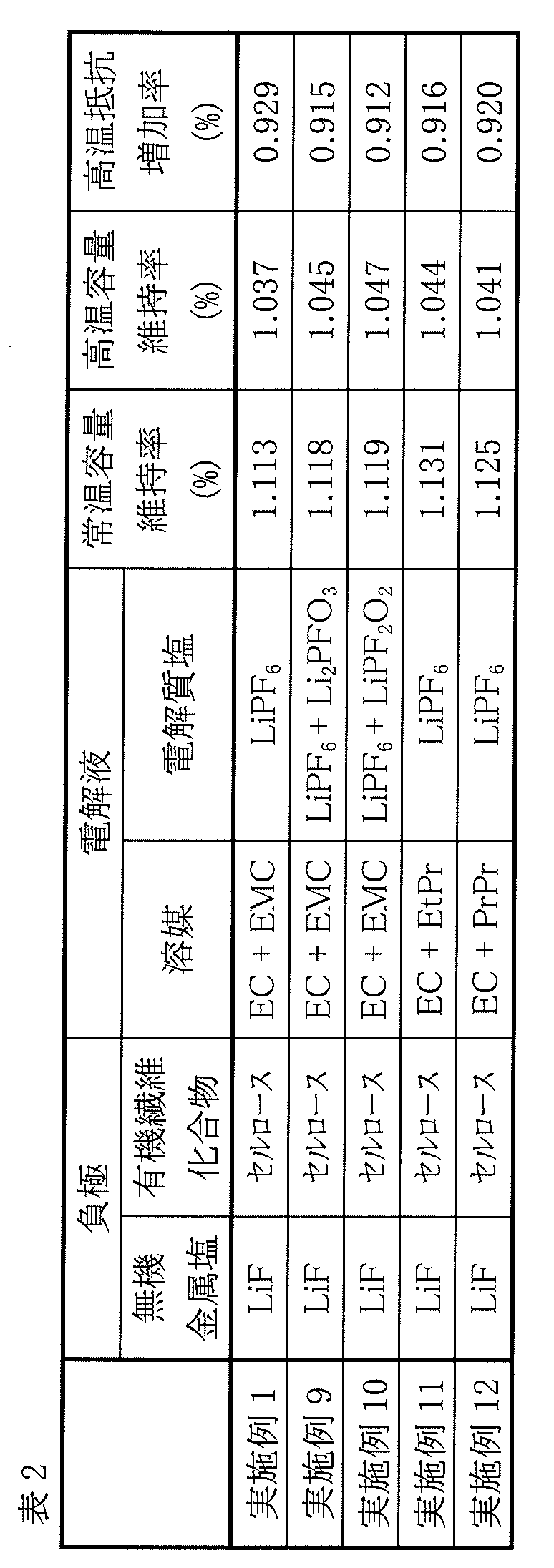
表1および表2に示した結果から、負極22が無機金属塩および有機繊維化合物を含んでいると、常温サイクル特性、高温サイクル特性および電気抵抗特性のそれぞれが改善された。よって、二次電池において優れたサイクル特性および優れた電気抵抗特性が得られた。
Claims (8)
- 正極および負極と共に電解液を備え、
前記負極は、無機金属塩および有機繊維化合物を含む、
二次電池。 - 前記無機金属塩は、フッ化リチウムおよび炭酸リチウムのうちの少なくとも一方を含み、
前記有機繊維化合物は、セルロース、キチンおよびキトサンのうちの少なくとも1種を含む、
請求項1記載の二次電池。 - 前記負極は、負極活物質層を含み、
前記負極活物質層は、負極活物質と共に前記無機金属塩および前記有機繊維化合物を含む、
請求項1または請求項2に記載の二次電池。 - 前記負極は、負極活物質を含み、
前記負極活物質は、
電極反応物質を吸蔵放出する中心部と、
前記中心部の表面を被覆すると共に、前記無機金属塩および前記有機繊維化合物を含む被覆部と
を含む、請求項1または請求項2に記載の二次電池。 - 前記電解液は、モノフルオロリン酸リチウムおよびジフルオロリン酸リチウムのうちの少なくとも一方を含む、
請求項1ないし請求項4のいずれか1項に記載の二次電池。 - 前記電解液は、鎖状カルボン酸エステルを含む、
請求項1ないし請求項5のいずれか1項に記載の二次電池。 - リチウムイオン二次電池である、
請求項1ないし請求項6のいずれか1項に記載の二次電池。 - 無機金属塩および有機繊維化合物を含む、
二次電池用負極。
Priority Applications (3)
| Application Number | Priority Date | Filing Date | Title |
|---|---|---|---|
| CN202280019997.8A CN116964769A (zh) | 2021-03-11 | 2022-02-22 | 二次电池用负极以及二次电池 |
| JP2023505275A JP7626195B2 (ja) | 2021-03-11 | 2022-02-22 | 二次電池用負極および二次電池 |
| US18/239,481 US20230411592A1 (en) | 2021-03-11 | 2023-08-29 | Negative electrode for secondary battery, and secondary battery |
Applications Claiming Priority (2)
| Application Number | Priority Date | Filing Date | Title |
|---|---|---|---|
| JP2021039016 | 2021-03-11 | ||
| JP2021-039016 | 2021-03-11 |
Related Child Applications (1)
| Application Number | Title | Priority Date | Filing Date |
|---|---|---|---|
| US18/239,481 Continuation US20230411592A1 (en) | 2021-03-11 | 2023-08-29 | Negative electrode for secondary battery, and secondary battery |
Publications (1)
| Publication Number | Publication Date |
|---|---|
| WO2022190863A1 true WO2022190863A1 (ja) | 2022-09-15 |
Family
ID=83227703
Family Applications (1)
| Application Number | Title | Priority Date | Filing Date |
|---|---|---|---|
| PCT/JP2022/007289 Ceased WO2022190863A1 (ja) | 2021-03-11 | 2022-02-22 | 二次電池用負極および二次電池 |
Country Status (4)
| Country | Link |
|---|---|
| US (1) | US20230411592A1 (ja) |
| JP (1) | JP7626195B2 (ja) |
| CN (1) | CN116964769A (ja) |
| WO (1) | WO2022190863A1 (ja) |
Citations (8)
| Publication number | Priority date | Publication date | Assignee | Title |
|---|---|---|---|---|
| JPH04267051A (ja) * | 1991-02-21 | 1992-09-22 | Sanyo Electric Co Ltd | アルカリ蓄電池用ペースト式カドミウム負極の製造方法 |
| WO2012147837A1 (ja) * | 2011-04-28 | 2012-11-01 | 昭和電工株式会社 | リチウム二次電池用正極活物質の製造方法、リチウム二次電池用正極活物質及びリチウム二次電池 |
| JP2016024986A (ja) * | 2014-07-22 | 2016-02-08 | 日本ゼオン株式会社 | 電気化学素子電極用複合粒子の製造方法、電気化学素子電極用複合粒子、電気化学素子電極、および電気化学素子 |
| JP2018522369A (ja) * | 2015-05-13 | 2018-08-09 | コリア フォレスト リサーチ インスティテュートKorea Forest Research Institute | 3次元網構造形態の電気化学素子用電極、その製造方法およびこれを含む電気化学素子 |
| WO2019058841A1 (ja) * | 2017-09-19 | 2019-03-28 | 株式会社 東芝 | 電極、二次電池、電池パック及び車両 |
| JP2020057500A (ja) * | 2018-10-01 | 2020-04-09 | トヨタ自動車株式会社 | 負極、電池、および負極の製造方法 |
| WO2020090014A1 (ja) * | 2018-10-30 | 2020-05-07 | Attaccato合同会社 | 非水電解質二次電池および非水電解質二次電池の製造方法 |
| WO2020088577A1 (en) * | 2018-11-02 | 2020-05-07 | Volt14 Solutions | Binder for battery electrode |
Family Cites Families (2)
| Publication number | Priority date | Publication date | Assignee | Title |
|---|---|---|---|---|
| KR20130090913A (ko) * | 2005-10-20 | 2013-08-14 | 미쓰비시 가가꾸 가부시키가이샤 | 리튬 2 차 전지 및 그것에 사용하는 비수계 전해액 |
| JP6474548B2 (ja) * | 2014-01-16 | 2019-02-27 | 信越化学工業株式会社 | 非水電解質二次電池用負極材及び負極活物質粒子の製造方法 |
-
2022
- 2022-02-22 WO PCT/JP2022/007289 patent/WO2022190863A1/ja not_active Ceased
- 2022-02-22 CN CN202280019997.8A patent/CN116964769A/zh active Pending
- 2022-02-22 JP JP2023505275A patent/JP7626195B2/ja active Active
-
2023
- 2023-08-29 US US18/239,481 patent/US20230411592A1/en active Pending
Patent Citations (8)
| Publication number | Priority date | Publication date | Assignee | Title |
|---|---|---|---|---|
| JPH04267051A (ja) * | 1991-02-21 | 1992-09-22 | Sanyo Electric Co Ltd | アルカリ蓄電池用ペースト式カドミウム負極の製造方法 |
| WO2012147837A1 (ja) * | 2011-04-28 | 2012-11-01 | 昭和電工株式会社 | リチウム二次電池用正極活物質の製造方法、リチウム二次電池用正極活物質及びリチウム二次電池 |
| JP2016024986A (ja) * | 2014-07-22 | 2016-02-08 | 日本ゼオン株式会社 | 電気化学素子電極用複合粒子の製造方法、電気化学素子電極用複合粒子、電気化学素子電極、および電気化学素子 |
| JP2018522369A (ja) * | 2015-05-13 | 2018-08-09 | コリア フォレスト リサーチ インスティテュートKorea Forest Research Institute | 3次元網構造形態の電気化学素子用電極、その製造方法およびこれを含む電気化学素子 |
| WO2019058841A1 (ja) * | 2017-09-19 | 2019-03-28 | 株式会社 東芝 | 電極、二次電池、電池パック及び車両 |
| JP2020057500A (ja) * | 2018-10-01 | 2020-04-09 | トヨタ自動車株式会社 | 負極、電池、および負極の製造方法 |
| WO2020090014A1 (ja) * | 2018-10-30 | 2020-05-07 | Attaccato合同会社 | 非水電解質二次電池および非水電解質二次電池の製造方法 |
| WO2020088577A1 (en) * | 2018-11-02 | 2020-05-07 | Volt14 Solutions | Binder for battery electrode |
Also Published As
| Publication number | Publication date |
|---|---|
| CN116964769A (zh) | 2023-10-27 |
| JPWO2022190863A1 (ja) | 2022-09-15 |
| JP7626195B2 (ja) | 2025-02-04 |
| US20230411592A1 (en) | 2023-12-21 |
Similar Documents
| Publication | Publication Date | Title |
|---|---|---|
| JP7432607B2 (ja) | 正極片、当該正極片を含む電気化学装置及び電子装置 | |
| JP7259863B2 (ja) | リチウムイオン二次電池用負極およびリチウムイオン二次電池 | |
| JP7468621B2 (ja) | 二次電池 | |
| WO2023063008A1 (ja) | 二次電池 | |
| WO2022196266A1 (ja) | 二次電池 | |
| WO2022244363A1 (ja) | 二次電池用負極および二次電池 | |
| JP2023089516A (ja) | 正極活物質、正極および二次電池 | |
| CN110582877A (zh) | 锂离子二次电池用负极及锂离子二次电池 | |
| JP7127692B2 (ja) | リチウムイオン二次電池用電解液およびリチウムイオン二次電池 | |
| JP7816566B2 (ja) | 二次電池用負極および二次電池 | |
| JP7845484B2 (ja) | 二次電池用負極および二次電池 | |
| JP7302731B2 (ja) | 二次電池 | |
| WO2023120688A1 (ja) | 二次電池 | |
| WO2023162518A1 (ja) | 二次電池 | |
| WO2023286579A1 (ja) | 二次電池用負極および二次電池 | |
| JP7747055B2 (ja) | 二次電池用負極および二次電池 | |
| CN113169304B (zh) | 二次电池 | |
| JP7626195B2 (ja) | 二次電池用負極および二次電池 | |
| JP7694802B2 (ja) | 二次電池用負極および二次電池 | |
| JP7823777B2 (ja) | 二次電池用負極および二次電池 | |
| JP7331950B2 (ja) | 二次電池用負極および二次電池 | |
| JP7648601B2 (ja) | 二次電池 | |
| JP7462142B2 (ja) | 二次電池 | |
| JP7715362B2 (ja) | 二次電池用電解液および二次電池 | |
| CN115336063B (en) | Secondary battery |
Legal Events
| Date | Code | Title | Description |
|---|---|---|---|
| 121 | Ep: the epo has been informed by wipo that ep was designated in this application |
Ref document number: 22766825 Country of ref document: EP Kind code of ref document: A1 |
|
| ENP | Entry into the national phase |
Ref document number: 2023505275 Country of ref document: JP Kind code of ref document: A |
|
| WWE | Wipo information: entry into national phase |
Ref document number: 202280019997.8 Country of ref document: CN |
|
| NENP | Non-entry into the national phase |
Ref country code: DE |
|
| 122 | Ep: pct application non-entry in european phase |
Ref document number: 22766825 Country of ref document: EP Kind code of ref document: A1 |