WO2022186253A1 - 回転切削工具 - Google Patents
回転切削工具 Download PDFInfo
- Publication number
- WO2022186253A1 WO2022186253A1 PCT/JP2022/008779 JP2022008779W WO2022186253A1 WO 2022186253 A1 WO2022186253 A1 WO 2022186253A1 JP 2022008779 W JP2022008779 W JP 2022008779W WO 2022186253 A1 WO2022186253 A1 WO 2022186253A1
- Authority
- WO
- WIPO (PCT)
- Prior art keywords
- cutting tool
- rotary cutting
- back surface
- seat
- tip
- Prior art date
- Legal status (The legal status is an assumption and is not a legal conclusion. Google has not performed a legal analysis and makes no representation as to the accuracy of the status listed.)
- Ceased
Links
Images








Classifications
-
- B—PERFORMING OPERATIONS; TRANSPORTING
- B22—CASTING; POWDER METALLURGY
- B22F—WORKING METALLIC POWDER; MANUFACTURE OF ARTICLES FROM METALLIC POWDER; MAKING METALLIC POWDER; APPARATUS OR DEVICES SPECIALLY ADAPTED FOR METALLIC POWDER
- B22F7/00—Manufacture of composite layers, workpieces, or articles, comprising metallic powder, by sintering the powder, with or without compacting wherein at least one part is obtained by sintering or compression
-
- B—PERFORMING OPERATIONS; TRANSPORTING
- B22—CASTING; POWDER METALLURGY
- B22F—WORKING METALLIC POWDER; MANUFACTURE OF ARTICLES FROM METALLIC POWDER; MAKING METALLIC POWDER; APPARATUS OR DEVICES SPECIALLY ADAPTED FOR METALLIC POWDER
- B22F7/00—Manufacture of composite layers, workpieces, or articles, comprising metallic powder, by sintering the powder, with or without compacting wherein at least one part is obtained by sintering or compression
- B22F7/06—Manufacture of composite layers, workpieces, or articles, comprising metallic powder, by sintering the powder, with or without compacting wherein at least one part is obtained by sintering or compression of composite workpieces or articles from parts, e.g. to form tipped tools
- B22F7/08—Manufacture of composite layers, workpieces, or articles, comprising metallic powder, by sintering the powder, with or without compacting wherein at least one part is obtained by sintering or compression of composite workpieces or articles from parts, e.g. to form tipped tools with one or more parts not made from powder
-
- B—PERFORMING OPERATIONS; TRANSPORTING
- B23—MACHINE TOOLS; METAL-WORKING NOT OTHERWISE PROVIDED FOR
- B23B—TURNING; BORING
- B23B27/00—Tools for turning or boring machines; Tools of a similar kind in general; Accessories therefor
- B23B27/14—Cutting tools of which the bits or tips or cutting inserts are of special material
-
- B—PERFORMING OPERATIONS; TRANSPORTING
- B23—MACHINE TOOLS; METAL-WORKING NOT OTHERWISE PROVIDED FOR
- B23B—TURNING; BORING
- B23B27/00—Tools for turning or boring machines; Tools of a similar kind in general; Accessories therefor
- B23B27/14—Cutting tools of which the bits or tips or cutting inserts are of special material
- B23B27/18—Cutting tools of which the bits or tips or cutting inserts are of special material with cutting bits or tips or cutting inserts rigidly mounted, e.g. by brazing
- B23B27/20—Cutting tools of which the bits or tips or cutting inserts are of special material with cutting bits or tips or cutting inserts rigidly mounted, e.g. by brazing with diamond bits or cutting inserts
-
- B—PERFORMING OPERATIONS; TRANSPORTING
- B23—MACHINE TOOLS; METAL-WORKING NOT OTHERWISE PROVIDED FOR
- B23C—MILLING
- B23C5/00—Milling-cutters
- B23C5/02—Milling-cutters characterised by the shape of the cutter
- B23C5/10—Shank-type cutters, i.e. with an integral shaft
-
- B—PERFORMING OPERATIONS; TRANSPORTING
- B23—MACHINE TOOLS; METAL-WORKING NOT OTHERWISE PROVIDED FOR
- B23C—MILLING
- B23C5/00—Milling-cutters
- B23C5/16—Milling-cutters characterised by physical features other than shape
- B23C5/18—Milling-cutters characterised by physical features other than shape with permanently-fixed cutter-bits or teeth
Definitions
- the present invention is a hard sintered body containing a polycrystalline diamond (PCD) sintered body and/or a cubic boron nitride (CBN) sintered body for processing non-ferrous metals such as aluminum and aluminum alloys, wood, resin, CFRP, etc. It relates to a rotary cutting tool having a hollow cutting edge and a tip helix angle.
- PCD polycrystalline diamond
- CBN cubic boron nitride
- the cutting edge of a rotary cutting tool may be formed from a hard sintered body.
- a hard sintered body In conventional rotary cutting tools with a helix angle, when forming a cutting edge made of a hard sintered body, it is manufactured by grinding a round bar formed by sintering PCD together with a cemented carbide body.
- the hard sintered bodies were spirally arranged in accordance with the torsion angle of the cutting edge (Patent Documents 1 to 4, etc.).
- the present invention has been completed in view of the above-mentioned circumstances, and the problem to be solved is to provide a rotary cutting tool having a cutting edge with a helix angle that can be manufactured more easily than before.
- a rotary cutting tool having a body with a tip joined to a seat comprising: The back surface of the seat is flat and inclined with respect to the axis of the rotary cutting tool, and the rake face and the flank face are curved surfaces, In the effective range of the cutting edge, the difference between the maximum value and the minimum value of each of the helix angle with respect to the axis of the rotary cutting tool and the relief angle and rake angle seen from a perpendicular cross section is 10 ° or less, When a plane that is perpendicular to the back surface of the seat and includes the axial center is viewed in the vertical direction, one of both ends of the back surface of the seat based on the axial
- the difference between the maximum value and the minimum value of each of the torsion angle, relief angle, and rake angle is preferably 5° or less, 3° or less, 2° or less, and more preferably 0°.
- the effective range of the cutting edge refers to the range from end to end of the cutting edge formed on the insert.
- the length in the radial direction of both ends of the tip is shorter than the length in the middle.
- the tip comprises a laminate of a hard sintered body layer made of a hard sintered body and a cemented carbide layer made of a cemented carbide forming a joint surface to be joined to the seat. It is preferable that the axial center side of the rake face is the cemented carbide layer at the end of the rake face.
- the rotary cutting tool of the present invention having the above configuration, can exhibit high performance by keeping the respective magnitudes of the clearance angle, the rake angle, and the helix angle within the predetermined ranges, and the back surface of the seat is flat. It becomes possible to manufacture simply because there is.
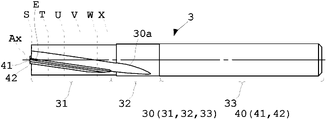
- FIG. 1 is a side view of the rotary cutting tool of Embodiment 1.
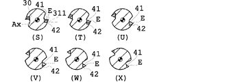
- FIG. 2 is an end view and a cross-sectional view of the rotary cutting tool of Embodiment 1, viewed from the left side of FIG.
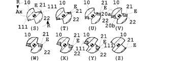
- the distance from the tip of the body is 0 mm for S, 5 mm for T, 10 mm for U, 15 mm for V, 20 mm for W, 25 mm for X, 30 mm for Y, and 34 mm for Z.
- 4 is a side view of the body of Embodiment 1.
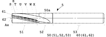
- FIG. 10 is a side view of the rotary cutting tool of Embodiment 2;
- FIG. 5 is an end view and a cross-sectional view of the rotary cutting tool of Embodiment 2, viewed from the left side of FIG.
- the distances from the tip (left side of the paper surface of FIG. 4) are 0 mm for S, 5 mm for T, 10 mm for U, 15 mm for V, 20 mm for W, and 23 mm for X.
- 8 is a side view of the body of Embodiment 2.
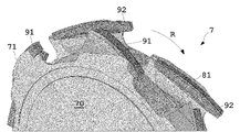
- FIG. FIG. 11 is a partial perspective view of the rotary cutting tool of Embodiment 3;
- FIG. 11 is a partial front view of the rotary cutting tool of Embodiment 3;
- FIG. 11 is a partial perspective view of members constituting the rotary cutting tool of Embodiment 3; 11 is an enlarged view of a portion where a chip is joined to the body of Embodiment 3.
- FIG. 1 is a side view of a conventional rotary cutting tool; FIG. It is the figure which looked at the plane perpendicular
- FIG. 12 is an end view and a cross-sectional view of a conventional rotary cutting tool seen from the left side of FIG. The distances from the tip (left side of the paper surface of FIG.
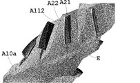
- FIG. 11 is a partial perspective view of the tip portion of the rotary cutting tool of Modified Mode 2;
- FIG. 14 is a partially enlarged view of FIG. 13;
- FIG. 11 is a partially enlarged front view of the tip portion of the rotary cutting tool of Modified Mode 2;
- the rotary cutting tool of the present invention will be described in detail below based on an embodiment.
- the rotary cutting tool of the present embodiment is a tool that has a cutting edge formed on the outer circumference and can perform cutting work on the outer circumference. A cutting edge can also be formed on the tip side.
- the rotary cutting tool of this embodiment can be suitably employed for milling cutters such as end mills.
- the cutting edge of the rotary cutting tool of this embodiment is made of a hard sintered body.
- the hard sintered body is made of PCD and/or CBN.
- the size of the rotary cutting tool of this embodiment is not particularly limited. The diameter can be 10 mm, 15 mm, 20 mm, 25 mm, 30 mm as a lower limit and 50 cm, 30 cm, 20 cm, 10 cm as an upper limit.
- the rotary cutting tool 1 of the present embodiment is a cutting tool that rotates counterclockwise (R direction in FIG. 2) when viewed from the tip side (left side in FIG. 1). is.
- the rotary cutting tool 1 has a body 10 (FIG. 3) and a tip 20 fixed on the back surface 111 of the seat provided in the groove 10a of the body 10.
- the groove 10a is a groove that is spirally formed in the outer peripheral portion of the blade portion 11 from the tip toward the rear. A chip 20 is bonded in this groove 10a.
- Two chips 20 are provided on the outer circumference of the body 10 at intervals of 180°, and are joined to the back surface 111 of the seat provided in the groove 10a at the joining surface 20a.
- the grooves 10a also have the function of discharging chips generated during cutting.
- FIG. 2 when a plane perpendicular to the back surface 111 of the seat and containing the axis Ax (a plane parallel to the paper surface of FIG. 1) is viewed in the vertical direction, the direction of the back surface 111 of the seat with respect to the direction of the axis Ax is shown.
- the left and right ends in FIG. 1 one end (the left end in FIG. 1, the tip) is positioned forward in the rotation direction of the rotary cutting tool 1 (upper in FIG.
- the seat back surface 311 is perpendicular to the seat back surface 311 and includes the axis Ax when viewed in the vertical direction. Both ends (one end and the other end) of the end with respect to the direction are all positioned behind the axis Ax in the rotation direction of the rotary cutting tool 5 (FIGS. 11 and 12 (S)).
- the body 10 is made of normal materials such as tool steel and cemented carbide.
- the body 10 is composed of a blade portion 11, a transition portion 12, and a shank portion 13 in order from the tip side in the axial center Ax direction.
- the blade portion 11 may be cylindrical or tapered.
- a back surface 111 of the seat which is a part of a plane inclined by a predetermined angle (10° for the rotary cutting tool 1) with respect to the axis Ax, which is the rotation axis of the rotary cutting tool 1, is provided in the groove 10a. formed.
- a chip 20 is joined to the back surface 111 and the bottom surface of the seat by welding such as brazing.
- the tip 20 has a joint surface 20a that is joined to the back surface 111 of the seat, and a cutting edge E is formed.
- the tip 20 has a two-layer structure in which a hard sintered body layer 21 made of a hard sintered body on which the cutting edge E is formed and a cemented carbide layer 22 made of a cemented carbide on the joint surface 20a side are joined.
- the tip 20 is formed by bonding a two-layer cuboid rough tip to the back surface 111 and the bottom surface of the seat of the body 10, and then discharging so that the rake angle and the clearance angle are constant in any cross-section of rotation in the axial direction.
- the cutting edge E can be formed by machining, laser machining, polishing with a diamond grindstone, or the like. Although not particularly limited here, the relief angle was 8° and the rake angle was 10°. It is easier to manufacture than forming the cutting edge E from the beginning and joining it on the back surface 111 of the seat. In addition, the method of forming the cutting edge E from the beginning is not excluded.
- the back surface 111 of the seat is a portion of a plane, ie a flat surface.
- a chip 20 is bonded onto the back surface 111 of the seat.
- the radial length of the back surface 111 of the seat is shorter near the front end and near the rear end.
- the rear surface 111 of the seat has a curved surface after passing over the joint surface on the rear end side.
- the chip 20 is a rectangular parallelepiped member having a surface (bonding surface 20a) that is perpendicular to the surface (bonding surface 20a) that is bonded to the back surface 111 of the seat and a surface (inner surface 20b) that is closer to the axis Ax is substantially parallel to the axis Ax. It is a face.
- a surface that intersects the back surface 111 of the seat of the body 10 and contacts the inner side surface 20b of the chip 20 has a shape complementary to the shape of the inner side surface 20b of the chip 20 (flat surface in this embodiment).
- the rotary cutting tool of this embodiment can be manufactured, for example, as follows.
- the body 10 is manufactured.
- the body 10 may be manufactured by cutting the entire body from the same bar material, or may be manufactured by separately forming a plurality of parts (for example, the blade part 11, the transition part 12, and the shank part 13) and then engaging them.
- a helical groove 10a extending rearward from the tip is formed in the blade portion 11 by cutting or the like.
- Also formed in the groove 10a is a back surface 111 of the seat to which the chip 20 is bonded.
- the formation of the back surface 111 of the seat may be the same as that of the groove 10a, or may be performed independently after the formation of the groove 10a.
- the chip 20 is joined to the back surface 111 and the bottom surface of the seat by brazing or the like.
- the tip 20 is formed by electric discharge machining, grinding, or the like to form a cutting edge E so as to have a predetermined flank surface and a predetermined rake surface.
- the cutting edge E is a ridgeline where the flank and rake face intersect.
- the portion of the tip 20 protruding outward from the outer peripheral surface of the body 10 is also removed by grinding or the like so as to have a predetermined diameter. In this configuration, the radial length at both ends (34 mm from the tip) of tip 20 is shorter than the length in the middle.
- the rotary cutting tool 5 of this embodiment has a body 50 and a tip 60.
- Body 50 (FIG. 6) has a similar construction, except that the slope of spiral groove 50a (i.e., the slope of tip 60) is 15° compared to 10° in body 10.
- the tip 60 has a two-layer structure in which a hard sintered body layer 61 and a cemented carbide layer 62 are joined together, and is different in fine shape formed by cutting according to the shape of the groove 50a provided in the body 50. It has the same configuration as the chip 20 .
- the seat back surface 511 is defined as one of the two ends of the seat back surface 511 with respect to the axis Ax direction when a plane that is perpendicular to the seat back surface 511 and includes the axis Ax is viewed in the vertical direction. is positioned forward in the rotational direction of the rotary cutting tool 5 from the axis Ax (FIG. 5 (S)), and the rear end (FIG. 5 (W) (X)) as the other end is located from the axis Ax to the rotary cutting tool 5 in the rotational direction.
- the seat back surface 311 is perpendicular to the seat back surface 311 and includes the axis Ax. It is positioned behind the center Ax in the rotational direction of the rotary cutting tool 5 (FIGS. 11 and 12(S)).
- the inclination of the tip 60 increases, the inclination of both ends of the tip 60 becomes too large in the configuration of the conventional rotary cutting tool, so that the tip 60 cannot be accommodated in the groove 50a, and the length of the tip 60 that can form the cutting edge E is shortened.
- the inclination (twist angle) is weakened.
- the radial length of the tip 60 that fits in the groove 50a of the body 50 can ensure the length necessary to form the cutting edge E.
- the length of the tip 60 in the axial center Ax direction becomes longer.
- the radial length at both ends (23 mm from the tip) of tip 60 is shorter than the length in the middle.
- the rotary cutting tool 7 of this embodiment is a tool that rotates in the direction of rotation R, and has bodies 70 and 80 and tips 90 (91 and 92).
- the bodies 70 and 80 are substantially disk-shaped members, and are integrated by being superimposed in the thickness direction (axial direction).
- the body 70 has six chips 91 arranged on the outer circumference so as to open outward in the axial direction in the rotational direction R (the angle with the axis is 70° counterclockwise). ) is placed.
- Six chips 92 arranged on the outer periphery of the body 80 are arranged so as to open outward in the axial direction in the rotational direction R (at an angle of 70 degrees clockwise with respect to the axial center). Tips 91 and 92 are arranged to axially overlap when bodies 70 and 80 are integrated.
- the bodies 70 and 80 are formed with chip joints 71 and 81 which are formed with flat seat back surfaces 711 and 811 at which the chips are mounted. 91 and 92 are joined. A plane perpendicular to the seat back surface 711 and including the axis is viewed in the vertical direction.
- the other end 71b is positioned further forward in the rotational direction of the rotary cutting tool 7 (lower in FIG. 8), and the other end 71b is positioned rearward in the rotational direction of the rotary cutting tool 7 (upper in FIG. 8) from the axis.
- the back surface 811 of the seat has a torsion angle opposite to that of the back surface 711 of the seat.
- one end 81a is positioned forward in the rotational direction of the rotary cutting tool 7 from the axis, and the other end 81b is positioned rearward in the rotational direction of the rotary cutting tool 7 from the axis.
- the inserts 91 and 92 are processed by electric discharge machining, laser machining, polishing, etc. so that the rake angle and clearance angle are constant at any part of the cutting edge.
- the inner side surface 20b near the axis Ax of the chip 20 is flat, but the portion of the inner side surface 20b near the axis Ax (around V in FIG. 2 and around U in FIG. 5) is flat. It is preferable to form the deepest concavity.
- the shape of the surface to be bonded to the chip can also be made complementary to the inner surface of the chip.
- the sizes of the chips 20 and 60 can be increased while maintaining the strength of the bodies 10 and 50.
- the radial length of the tip 60 is shorter than the length of the 10 mm portion because the inner surface of the tip 60 is This is because the size (radial length) of the tip 60 is determined so that sufficient strength can be exhibited based on the 10 mm portion (FIG. 5(U)) closest to the axis Ax.
- the radial length of the tip 60 may be insufficient at both ends, but the shape of the inner side surface of the tip 60 is a concave surface (the bottom surface of the seat) in which the vicinity of the portion closest to the axis Ax is recessed. Conversely, the tip 60 has a bulging shape in the vicinity of the center, so that the length of the tip 60 in the radial direction becomes longer as it goes away from the both ends. As a result, it is possible to lengthen the length of the tip 60 in the axial center Ax direction, so that the cutting edge E is lengthened, and in addition (or instead) the inclination of the cutting edge E is further increased. becomes possible.
- the back of the seat is basically flat, even if slight unevenness is provided around the periphery, or if grooves or dimples are formed, it is acceptable if it is almost flat except for the unevenness that has been formed. be done.
- the rotary cutting tool A1 of this modification is a tool that performs cutting by rotating counterclockwise when viewed from the tip side (upper right in FIG. 13).
- the rotary cutting tool A1 is fixed on the back surface of a body A10 provided with two grooves A10a at 180° intervals on the outer periphery and a seat A112 provided on the land portion between the two grooves A10a of the body A10. and a chip A20.
- the back of the seat is part of a plane, ie a flat surface.
- a bottom edge tip A30 and a front peripheral edge tip A40 are fixed to the tip of the body A10.
- the bottom cutting edge tip A30 has a cutting edge in a direction perpendicular to the axis Ax of the rotary cutting tool A1 of this modified mode, and the tip direction is machined by rotating the rotary cutting tool A1 of this modified mode.
- the front peripheral edge tip A40 is set to have a positive twist angle with respect to the axis Ax of the rotary cutting tool A1 of this modified mode, and the rotation of the rotary cutting tool A1 of this modified mode allows machining in the outer peripheral direction of the tip. do.
- the groove A10a is formed on the outer peripheral portion of the blade portion A11 so that the twist angle is positive from the tip toward the rear.
- the groove A10a also has the function of discharging chips generated during cutting.
- FIG. 15 when a plane that is perpendicular to the back surface of the seat and includes the axis Ax is viewed in the vertical direction, one end Tf of the two ends Tf and Te of the back surface of the seat based on the direction of the axis Ax is the axis center. It is located behind Ax in the rotational direction of the rotary cutting tool A1 (left in FIG. 15), and the other end Te is located forward in the rotational direction of the rotary cutting tool A1 from the axis Ax (right in FIG. 15).
- the four chips A20 provided on each of the lands are evenly arranged in the direction of the axis Ax of the body A10, and the chips A20 whose ends are adjacent to each other in the direction of the axis Ax are aligned with the other lands. It is placed in a position where it partially overlaps with the cutting edge of
- the tip A20 has a joint surface that is joined to the back surface of the seat, and a cutting edge E is formed.
- the tip A20 has a two-layer structure in which a hard sintered body layer A21 made of a hard sintered body on which the cutting edge E is formed and a cemented carbide layer A22 made of a cemented carbide on the joint surface side are joined.
- the chip A20 is formed by bonding a two-layer cuboid rough chip to the back and bottom surfaces of the seat of the body A10, and then performing electrical discharge machining and laser
- a curved cutting edge E can be formed by processing, polishing with a diamond grindstone, or the like.
- the relief angle was 8° and the rake angle was 10°.
- Set the clearance angle at one end of the tip (the tip side of the rotary cutting tool A1) to 15° and the rake angle to 5°. may It is easier to manufacture than forming the cutting edge E from scratch and joining it on the back of the seat.
- the method of forming the cutting edge E from the beginning is not excluded.
- the cutting resistance is reduced by increasing the twist angle of the tip A20, and the sharpness and accuracy of the machined surface are improved.
- the rake angle of the cutting edge E can be set to an appropriate value, so that the accuracy of the machined surface can be further improved.
- the chips are led out in the rear end direction through the grooves A10a formed to have a positive helix angle, the discharge of the chips is easier than in the case where the grooves are also formed to have a negative helix angle. Excellent for
Landscapes
- Engineering & Computer Science (AREA)
- Mechanical Engineering (AREA)
- Chemical & Material Sciences (AREA)
- Composite Materials (AREA)
- Manufacturing & Machinery (AREA)
- Materials Engineering (AREA)
- Milling Processes (AREA)
Priority Applications (2)
| Application Number | Priority Date | Filing Date | Title |
|---|---|---|---|
| CN202280007581.4A CN116490304B (zh) | 2021-03-02 | 2022-03-02 | 旋转切削工具 |
| JP2023503893A JP7842731B2 (ja) | 2021-03-02 | 2022-03-02 | 回転切削工具 |
Applications Claiming Priority (2)
| Application Number | Priority Date | Filing Date | Title |
|---|---|---|---|
| JP2021-032972 | 2021-03-02 | ||
| JP2021032972 | 2021-03-02 |
Publications (1)
| Publication Number | Publication Date |
|---|---|
| WO2022186253A1 true WO2022186253A1 (ja) | 2022-09-09 |
Family
ID=83154600
Family Applications (1)
| Application Number | Title | Priority Date | Filing Date |
|---|---|---|---|
| PCT/JP2022/008779 Ceased WO2022186253A1 (ja) | 2021-03-02 | 2022-03-02 | 回転切削工具 |
Country Status (3)
| Country | Link |
|---|---|
| JP (1) | JP7842731B2 (https=) |
| CN (1) | CN116490304B (https=) |
| WO (1) | WO2022186253A1 (https=) |
Cited By (1)
| Publication number | Priority date | Publication date | Assignee | Title |
|---|---|---|---|---|
| WO2024236898A1 (ja) * | 2023-05-12 | 2024-11-21 | 兼房株式会社 | エンドミルおよびエンドミルの製造方法 |
Citations (5)
| Publication number | Priority date | Publication date | Assignee | Title |
|---|---|---|---|---|
| JPH04102716U (ja) * | 1990-05-11 | 1992-09-04 | 三菱マテリアル株式会社 | エンドミル |
| JPH0570821U (ja) * | 1992-03-04 | 1993-09-24 | 住友電気工業株式会社 | 回転切削工具 |
| JP2002126933A (ja) * | 2000-10-25 | 2002-05-08 | Mmc Kobelco Tool Kk | エンドミル |
| US20090103992A1 (en) * | 2004-11-26 | 2009-04-23 | Kyocera Corporation | Cutting Insert and Milling Tool |
| WO2015018842A1 (en) * | 2013-07-19 | 2015-02-12 | Element Six Limited | Milling tools, method for making same and method of using same |
Family Cites Families (16)
| Publication number | Priority date | Publication date | Assignee | Title |
|---|---|---|---|---|
| JPS5322717B2 (https=) * | 1972-07-19 | 1978-07-10 | ||
| JPS615517U (ja) * | 1984-06-18 | 1986-01-14 | 日立ツール株式会社 | スパイラルエンドミル |
| JPH0741459B2 (ja) * | 1984-12-25 | 1995-05-10 | 日立金属株式会社 | 植刃式エンドミル |
| JPH04223810A (ja) * | 1990-09-19 | 1992-08-13 | G N Tool Kk | スロアーウェイチップ及びその製造方法 |
| JP2825035B2 (ja) * | 1991-11-21 | 1998-11-18 | 三菱マテリアル株式会社 | ボールエンドミル |
| JPH07246508A (ja) * | 1994-03-10 | 1995-09-26 | Kobe Steel Ltd | 高硬度材料加工用エンドミル |
| JPH09136209A (ja) * | 1995-11-16 | 1997-05-27 | Yutaka Giken Co Ltd | エンドミル |
| GB2354470B (en) * | 1999-05-24 | 2004-02-04 | Honda Motor Co Ltd | Cutting tip and manufacturing method thereof |
| JP2002018630A (ja) * | 2000-07-11 | 2002-01-22 | Dijet Ind Co Ltd | エンドミル |
| JP2002178211A (ja) * | 2000-12-14 | 2002-06-25 | Osg Corp | 超高圧cbn焼結体エンドミル |
| JP2004344984A (ja) * | 2003-05-20 | 2004-12-09 | Tungaloy Corp | エンドミル |
| JP4952171B2 (ja) * | 2006-09-29 | 2012-06-13 | 株式会社タンガロイ | スローアウェイ式回転工具 |
| JP2009125865A (ja) * | 2007-11-23 | 2009-06-11 | Osg Corp | エンドミル及びそのエンドミルの製造方法 |
| JP6606840B2 (ja) * | 2014-03-28 | 2019-11-20 | 三菱マテリアル株式会社 | 多結晶ダイヤモンド焼結体付き回転切削工具 |
| US10076795B2 (en) * | 2015-11-19 | 2018-09-18 | Iscar, Ltd. | Triangular tangential milling insert and milling tool |
| CN110014184B (zh) * | 2019-04-17 | 2020-01-31 | 哈尔滨理工大学 | 一种钛合金加工用渐变螺旋槽旋轮线铣刀及其磨削方法 |
-
2022
- 2022-03-02 WO PCT/JP2022/008779 patent/WO2022186253A1/ja not_active Ceased
- 2022-03-02 CN CN202280007581.4A patent/CN116490304B/zh active Active
- 2022-03-02 JP JP2023503893A patent/JP7842731B2/ja active Active
Patent Citations (5)
| Publication number | Priority date | Publication date | Assignee | Title |
|---|---|---|---|---|
| JPH04102716U (ja) * | 1990-05-11 | 1992-09-04 | 三菱マテリアル株式会社 | エンドミル |
| JPH0570821U (ja) * | 1992-03-04 | 1993-09-24 | 住友電気工業株式会社 | 回転切削工具 |
| JP2002126933A (ja) * | 2000-10-25 | 2002-05-08 | Mmc Kobelco Tool Kk | エンドミル |
| US20090103992A1 (en) * | 2004-11-26 | 2009-04-23 | Kyocera Corporation | Cutting Insert and Milling Tool |
| WO2015018842A1 (en) * | 2013-07-19 | 2015-02-12 | Element Six Limited | Milling tools, method for making same and method of using same |
Cited By (1)
| Publication number | Priority date | Publication date | Assignee | Title |
|---|---|---|---|---|
| WO2024236898A1 (ja) * | 2023-05-12 | 2024-11-21 | 兼房株式会社 | エンドミルおよびエンドミルの製造方法 |
Also Published As
| Publication number | Publication date |
|---|---|
| CN116490304B (zh) | 2026-04-24 |
| JP7842731B2 (ja) | 2026-04-08 |
| CN116490304A (zh) | 2023-07-25 |
| JPWO2022186253A1 (https=) | 2022-09-09 |
Similar Documents
| Publication | Publication Date | Title |
|---|---|---|
| US8202026B2 (en) | Cutting insert | |
| KR100639802B1 (ko) | 엔드밀용 인덱서블 인서트 및 이를 이용한 밀링공구 | |
| CN101557899B (zh) | 旋转切削工具 | |
| JP2013006221A (ja) | 切削インサート及び刃先交換式回転工具 | |
| JP6868023B2 (ja) | 連続的に湾曲するすくい隆起部と螺旋溝設計とを備えた超硬合金コーナーラジアスエンドミル | |
| JP6869492B2 (ja) | 切削インサート | |
| JP5814611B2 (ja) | エンドミル | |
| CA3009030A1 (en) | Cutting tool | |
| JP6704132B2 (ja) | ボールエンドミル | |
| WO2022186253A1 (ja) | 回転切削工具 | |
| KR960007687Y1 (ko) | 엔드밀 | |
| JPH07237027A (ja) | スローアウェイチップ及び切削工具 | |
| JP7527796B2 (ja) | 多刃ボールエンドミル及び多刃ボールエンドミルの加工方法 | |
| CN109414771B (zh) | 切削刀片及可转位刀片式旋转切削工具 | |
| JP6413280B2 (ja) | ボールエンドミル | |
| CN111421173B (zh) | 坯体以及具有螺旋状超硬材料前刀面的切削工具 | |
| KR102316725B1 (ko) | 다결정다이아몬드 소재의 절삭날이 결합된 엔드밀 | |
| JP2021504157A (ja) | 材料体積に対するボイド体積の比率が高い片面三方向割出し可能なミーリングインサートおよびそのためのインサートミル | |
| JP6902284B2 (ja) | 切削工具 | |
| JPH0549408B2 (https=) | ||
| JP7313599B2 (ja) | 硬質焼結体用の基材、硬質焼結体および切削工具 | |
| JP7706561B2 (ja) | 回転工具、及び切削加工物の製造方法 | |
| JP7473711B1 (ja) | 回転式切削工具及びその製造方法 | |
| JP3097192B2 (ja) | エンドミル | |
| JP2002126930A (ja) | 多刃ボールエンドミル |
Legal Events
| Date | Code | Title | Description |
|---|---|---|---|
| 121 | Ep: the epo has been informed by wipo that ep was designated in this application |
Ref document number: 22763307 Country of ref document: EP Kind code of ref document: A1 |
|
| ENP | Entry into the national phase |
Ref document number: 2023503893 Country of ref document: JP Kind code of ref document: A |
|
| WWE | Wipo information: entry into national phase |
Ref document number: 202280007581.4 Country of ref document: CN |
|
| NENP | Non-entry into the national phase |
Ref country code: DE |
|
| 122 | Ep: pct application non-entry in european phase |
Ref document number: 22763307 Country of ref document: EP Kind code of ref document: A1 |