WO2022185912A1 - 端子装置 - Google Patents
端子装置 Download PDFInfo
- Publication number
- WO2022185912A1 WO2022185912A1 PCT/JP2022/006094 JP2022006094W WO2022185912A1 WO 2022185912 A1 WO2022185912 A1 WO 2022185912A1 JP 2022006094 W JP2022006094 W JP 2022006094W WO 2022185912 A1 WO2022185912 A1 WO 2022185912A1
- Authority
- WO
- WIPO (PCT)
- Prior art keywords
- pressing member
- pressing
- insertion hole
- locking
- terminal
- Prior art date
- Legal status (The legal status is an assumption and is not a legal conclusion. Google has not performed a legal analysis and makes no representation as to the accuracy of the status listed.)
- Ceased
Links
Images




Classifications
-
- H—ELECTRICITY
- H01—ELECTRIC ELEMENTS
- H01R—ELECTRICALLY-CONDUCTIVE CONNECTIONS; STRUCTURAL ASSOCIATIONS OF A PLURALITY OF MUTUALLY-INSULATED ELECTRICAL CONNECTING ELEMENTS; COUPLING DEVICES; CURRENT COLLECTORS
- H01R4/00—Electrically-conductive connections between two or more conductive members in direct contact, i.e. touching one another; Means for effecting or maintaining such contact; Electrically-conductive connections having two or more spaced connecting locations for conductors and using contact members penetrating insulation
- H01R4/28—Clamped connections, spring connections
- H01R4/48—Clamped connections, spring connections utilising a spring, clip, or other resilient member
-
- H—ELECTRICITY
- H01—ELECTRIC ELEMENTS
- H01R—ELECTRICALLY-CONDUCTIVE CONNECTIONS; STRUCTURAL ASSOCIATIONS OF A PLURALITY OF MUTUALLY-INSULATED ELECTRICAL CONNECTING ELEMENTS; COUPLING DEVICES; CURRENT COLLECTORS
- H01R25/00—Coupling parts adapted for simultaneous co-operation with two or more identical counterparts, e.g. for distributing energy to two or more circuits
Definitions
- the present disclosure relates to terminal devices.
- a quick-connect terminal for an outlet for electrically connecting an electric wire inserted through an insertion hole formed in a housing to an outlet blade receiver.
- a quick-connect terminal for an outlet consists of a connecting portion that is electrically connected by elastic contact with a wire, a retaining piece that has a retaining piece that prevents the wire from coming off, and a retaining piece that is attached to the wire. and an unlocking member for releasing the locking action.
- the quick-connect terminal of the outlet when the release button of the unlocking member is pushed, the sliding portion of the unlocking member slides and moves into the housing, so that the unlocking piece becomes the retaining piece. The electric wire locking action is released, and the electric wire can be pulled out.
- an object of the present disclosure is to provide a terminal device capable of realizing an insertion/removal operation with a simple procedure.
- a terminal device includes a terminal, a housing formed with an insertion hole into which an electric wire for electrically connecting to the terminal is inserted, and an elastic contact with the electric wire inserted from the insertion hole.
- an elastic member that electrically connects the electric wire and the terminal, and a pressing member that is pressed along the pressing direction are provided, and the pressing member is arranged in a vertical direction that is perpendicular to the pressing direction. and elastically deforming the elastic member by being pressed in the pressing direction when the insertion hole and the elastic member are viewed so as to face the opening surface of the insertion hole.
- the area of the region of the elastic member that overlaps the insertion hole is reduced, and the housing engages with the convex portion in a state in which the pressing member elastically deforms the elastic member, thereby moving the pressing member. It has a locking portion for locking.
- the terminal device of the present disclosure it is possible to implement the insertion/removal work with a simple procedure.
- FIG. 1 is a perspective view showing the appearance of the wiring accessories concerning an embodiment.
- FIG. 2A is a perspective view showing how the pressing member of the wiring device according to the embodiment is pressed.
- FIG. 2B is a perspective view showing how an electric wire is inserted into the first insertion hole after the pressing member of the wiring device according to the embodiment is pressed and rotated.
- FIG. 3 is an exploded perspective view showing the wiring accessory according to the embodiment.
- FIG. 4A is a perspective view showing the wiring device inside the main body cover when the locking state of the pressing member of the wiring device according to the embodiment is released.
- 4B is a perspective view showing the wiring device inside the main body cover when the pressing member of the wiring device according to the embodiment is in the locked state;
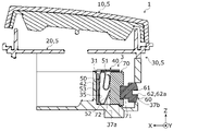
- FIG. 5A is a cross-sectional view taken along line AA of FIG. 1 showing a state in which the pressing member of the wiring device is unlocked.
- FIG. 5B is a cross-sectional view showing the case where the pressing member of the wiring device is in the locked state.
- FIG. 6A is a cross-sectional view taken along line BB of FIG. 5A showing a case where the locking state of the pressing member of the wiring device is released.
- FIG. 6B is a cross-sectional view showing the case where the pressing member of the wiring device is in the locked state.
- FIG. 7A is a cross-sectional view taken along line CC of FIG. 5A showing a case where the locking state of the pressing member of the wiring device is released.
- FIG. 7B is a cross-sectional view showing the case where the pressing member of the wiring device is in the locked state.
- FIG. 7C is a cross-sectional view showing the electric wire when the locking state of the pressing member of the wiring device is released.
- FIG. 8 is a perspective view showing how the pressing member of the wiring device according to the modification of the embodiment is pressed.
- each figure is a schematic diagram and is not necessarily strictly illustrated. Moreover, in each figure, the same code
- the direction in which the main body case and the cover supporting portion overlap is defined as the Z-axis direction
- the longitudinal direction of the wiring device is defined as the X-axis direction
- the direction perpendicular to the Z-axis direction and the X-axis direction is defined as the Y-axis direction.
- the direction in which the pressing member is pressed in the X-axis direction is the positive side direction
- the depth side of the paper surface of FIG. 1 is the positive side direction in the Y-axis direction
- the electric wire is inserted into the first insertion hole in the Z-axis direction. Let the direction be the direction of the plus side.
- FIG. 1 is a perspective view showing the appearance of wiring accessory 1 according to the embodiment.
- the wiring device 1 is, for example, a connection device that supplies power to a facility system such as a lighting device and a blower installed in a facility, and cuts off the power supply.
- the wiring accessories 1 are embedded in structures such as ceilings and walls.
- the wiring device 1 is, for example, an outlet or a switch.
- the wiring accessory 1 is formed in a vertically long rectangular parallelepiped shape when viewed from the front along the negative direction of the Z axis.
- FIG. 2A is a perspective view showing how the pressing member 60 of the wiring device 1 according to the embodiment is pressed.
- FIG. 2B is a perspective view showing how the wire 90 is inserted into the first insertion hole 37a after the pressing member 60 of the wiring device 1 according to the embodiment is pressed and rotated.
- the tool 91 when connecting the electric wire 90 to the wiring device 1, the tool 91 is engaged with the pressing member 60, pushed in the positive direction of the X-axis, and rotated. Then, since the pressing member 60 is maintained in the pushed state, the operator releases the tool 91 and inserts the electric wire 90 into the first insertion hole 37 a of the wiring device 1 , thereby inserting the electric wire 90 into the wiring device 1 . can be electrically connected to The wiring accessories 1 will be described in more detail below.
- the tool 91 is a Phillips screwdriver, a minus screwdriver, a wrench, or the like.
- FIG. 3 is an exploded perspective view showing the wiring device 1 according to the embodiment.
- the wiring device 1 includes a housing 5 and a terminal device 3.
- the housing 5 is a housing that accommodates the terminal device 3, and a part of the housing 5 is embedded in a structure such as a ceiling or a wall.
- the housing 5 is a socket housing or a switch housing.
- the housing 5 has a body cover 10 , a cover support portion 20 and a body case 30 .
- the main body cover 10 has a flat, substantially rectangular shape, and is the front surface of the wiring device 1 (the surface on the Z-axis positive direction side). is arranged on the Z-axis plus direction side.
- the body cover 10 forms part of the outer shell of the housing 5 .
- the main body cover 10 is rotatably fixed to the cover support portion 20 by being connected to the cover support portion 20 .
- the body cover 10 has a rotating shaft portion 11 formed on each of the side surface in the positive direction of the Y axis and the side surface in the negative direction of the Y axis.
- Each rotation shaft portion 11 is an intermediate portion of the main body cover 10 in the X-axis direction, and is arranged side by side along the Y-axis direction.
- Each rotating shaft portion 11 slides with respect to the hole portion 21 by being inserted into the hole portion 21 formed in the cover support portion 20 .
- the main body cover 10 rotates about each of the rotation shafts 11 as a fulcrum by the operator's operation.
- the cover support part 20 has a substantially rectangular plate shape and is arranged so as to be sandwiched between the main body cover 10 and the main body case 30 .
- the cover support part 20 is fixed to the structure directly or via a support frame or the like. Thereby, wiring accessories 1 are fixed to a structure.
- the cover support part 20 is connected and fixed to the main body case 30 so as to cover the opening of the main body case 30 .
- the cover support portion 20 has a hole portion 21 formed in each of the side surface in the positive Y-axis direction and the side surface in the negative Y-axis direction.
- Each hole 21 is an intermediate portion in the X-axis direction of the main body cover 10, and is arranged so as to line up along the Y-axis direction.
- the rotation shaft portions 11 formed in the cover support portion 20 are inserted into the respective hole portions 21 in a one-to-one relationship, so that the respective hole portions 21 rotatably support the main body cover 10. ing.
- the body case 30 has a cubic outer shape, has a bottom portion on the Z-axis negative direction side, and has an opening on the Z-axis positive direction side.
- the body case 30 is formed with a first insertion hole 37a for inserting and removing the electric wire 90 and a second insertion hole 37b for arranging the pressing member 60 of the terminal device 3 .
- a wire 90 for electrical connection with the terminal 40 is inserted into the first insertion hole 37a.
- the first insertion hole 37a is formed in the bottom portion of the main body case 30 on the negative direction side of the X axis. Although a plurality of first insertion holes 37a are formed in the present embodiment, only one may be formed.
- the first insertion hole 37a is an example of an insertion hole.
- the second insertion hole 37b is formed in the side wall portion of the main body case 30 on the negative direction side of the X axis.
- first insertion hole 37a and the second insertion hole 37b are arranged so as to be close to each other. For this reason, the first insertion hole 37a and the second insertion hole 37b are formed at corners including the bottom of the body case 30 . Although a plurality of second insertion holes 37b are formed in the present embodiment, only one may be formed.
- FIG. 4A is a perspective view showing the wiring device 1 inside the main body cover 10 when the locking state of the pressing member 60 of the wiring device 1 according to the embodiment is released.
- FIG. 4B is a perspective view showing the wiring device 1 inside the body cover 10 when the pressing member 60 of the wiring device 1 according to the embodiment is in the locked state. 4A and 4B, illustration of the terminal 40 is omitted.
- the body case 30 is formed with a housing chamber 35 for housing the terminal device 3 .
- the accommodation chamber 35 communicates with the first insertion hole 37a and the second insertion hole 37b.
- a plurality of protrusions are formed on the bottom of the main body case 30 .
- the plurality of protrusions defines a storage chamber 35 and supports the terminal device 3 and the like stored in the body case 30 .
- the plurality of protrusions have supporting pieces 31 that support the terminals 40 of the terminal device 3 and convex walls 32 that support the terminals 40 and contact the pressing member 60 .
- the support piece 31 is a wall protruding from the bottom of the body case 30 in the positive direction of the Z axis, and is formed around the terminal 40 so as to hold the posture of the terminal 40 arranged in the body case 30 .
- the convex wall 32 is formed along the inner wall of the body case 30 so as to avoid interference with the pressing member 60 and the transmission member 70 .
- a locking portion 33 is provided on the body case 30 .
- the locking portion 33 is formed by a wall portion that forms the second insertion hole 37b of the main body case 30 . As shown in FIG. 4B , when the pressing member 60 is in the locked state (locked by the locking portion 33 ), the convex wall 32 of the pressing member 60 is caught by the locking portion 33 .
- the stopping portion 33 can suppress movement of the pressing member 60 in the negative direction of the X axis.
- Terminal device 3 As shown in FIGS. 2B, 3, 4A and 4B, the terminal device 3 is arranged in the housing 5 for electrical connection with the electric wire 90 inserted through the first insertion hole 37a formed in the housing 5. It is
- the terminal device 3 includes a terminal 40 , a locking spring 50 , a pressing member 60 and a transmission member 70 .
- the terminal 40 is a quick-connect terminal capable of housing the locking spring 50 inside.
- the terminal 40 is accommodated in a housing chamber for the terminal 40, and includes a terminal plate 41 electrically connected to the electric wire 90, an opposing plate 42 disposed on the opposite side of the terminal plate 41 via the locking spring 50, and a terminal It has a connection portion 43 that connects the plate 41 and the opposing plate 42 .
- the electric wire 90 is inserted through the first insertion hole 37 a of the main body case 30 , the electric wire 90 pressed against the locking spring 50 and the terminal plate 41 are electrically connected.
- the terminal 40 has a pair of terminal plates 41 .
- a slit 44 is formed between the pair of terminal plates 41 to allow the locking spring 50 housed in the terminal 40 to be exposed.
- a transmission member 70 is inserted into the slit 44 .
- the locking spring 50 electrically connects the electric wire 90 and the terminal 40 by elastically contacting the electric wire 90 inserted from the first insertion hole 37a.
- the locking spring 50 is arranged to face the first insertion hole 37a. That is, the locking spring 50 is exposed when viewed along the Z-axis direction.
- the locking spring 50 is an example of an elastic member.
- FIG. 5A is a cross-sectional view taken along line AA of FIG. 1 and showing a case where the locking state of the pressing member 60 of the wiring device 1 is released.
- FIG. 5B is a cross-sectional view showing the case where the pressing member 60 of the wiring device 1 is in the locked state.
- the locking spring 50 is arranged at a position facing the S-shaped connecting piece 51 and the opening of the first insertion hole 37a when viewed along the Y-axis direction. and a center piece 53 that connects the connecting piece 51 and the locking piece 52 and is held by the opposing plate 42 of the terminal 40 .
- the lock piece 52 is exposed from the first insertion hole 37a.
- the connecting piece 51 and the locking piece 52 are arranged so as to face or contact the terminal plate 41 of the terminal 40 .
- the connecting piece 51 and the locking piece 52 can indirectly press the terminal plate 41 of the terminal 40 via the electric wire 90 .
- the locking spring 50 may not have the connection piece 51 , and the connection piece 51 is not an essential component of the locking spring 50 .
- the locking spring 50 is elastically deformed when the transmission member 70 inserted into the slit 44 of the terminal 40 is pressed along the pressing direction (X-axis plus direction). Specifically, since the connecting piece 51 and the locking piece 52 of the locking spring 50 are in contact with the transmission member 70, the pressing member 60 is pressed along the pressing direction, thereby The member 70 moves in the positive direction of the X axis, the connecting piece 51 and the locking piece 52 are elastically deformed (in an elastically deformed state), and the connecting piece 51 and the locking piece 52 are separated from the terminal plate 41 of the terminal 40. , a gap into which the electric wire 90 can be inserted is formed.
- the electric wire 90 can be arranged between the terminal plate 41 and the connecting piece 51 and the locking piece 52.
- the locking spring 50 can be displaced by elastic deformation to a state in which the wire 90 can be inserted so that the wire 90 can be electrically connected to the terminal 40 .
- the locking spring 50 has a pair of connecting pieces 51, a pair of locking pieces 52, and a pair of central pieces 53.
- the pair of connecting pieces 51 and the pair of locking pieces 52 are in one-to-one correspondence with the pair of terminal plates 41 . That is, since the pair of connecting pieces 51 and the pair of locking pieces 52 are in one-to-one correspondence with the two adjacent first insertion holes 37a, the pressing member 60 and the transmission member 70 are pressed along the pressing direction. Then, the pair of connecting pieces 51 and the pair of locking pieces 52 are elastically deformed. When the pair of connecting pieces 51 and the pair of locking pieces 52 are elastically deformed, the wires 90 can be simultaneously inserted into and removed from the two adjacent first insertion holes 37a.
- the locking spring 50 may have three or more connecting pieces 51, three or more locking pieces 52, and three or more central pieces 53.
- the terminal plate 41 may also have three or more so as to correspond one-to-one with the three or more connection pieces 51 and the three or more locking pieces 52 .
- the three or more connecting pieces 51 and the three or more locking pieces 52 may correspond one-to-one with the three or more first insertion holes 37a. Therefore, by pressing one pressing member 60, the electric wires 90 may be simultaneously inserted into and removed from three or more first insertion holes 37a.
- one locking spring 50 corresponds to two first insertion holes 37a, but it is not limited to this.
- one locking spring 50 may correspond to three or more first insertion holes 37a, and one locking spring 50 may correspond to one first insertion hole 37a.
- One locking spring 50 may be elastically deformed by one or more pressing members 60 and one or more transmission members 70 .
- FIG. 6A is a cross-sectional view taken along the line BB in FIG. 5A showing the case where the pressing member 60 of the wiring device 1 is released from the locking state.
- FIG. 6B is a cross-sectional view showing the case where the pressing member 60 of the wiring device 1 is in the locked state.
- FIG. 7A is a cross-sectional view taken along line CC of FIG. 5A showing a case where the locking state of the pressing member 60 of the wiring device 1 is released.
- FIG. 7B is a cross-sectional view showing the case where the pressing member 60 of the wiring device 1 is in the locked state.
- FIG. 7C is a cross-sectional view showing the electric wire 90 when the locking state of the pressing member 60 of the wiring device 1 is released.
- the pressing member 60 is held by the body case 30 while being inserted into the second insertion hole 37b of the body case 30. As shown in FIGS. Since the head portion 62 of the pressing member 60 is exposed from the main body case 30, the pressing member 60 is pressed along the pressing direction. When the pressing member 60 is pressed in the pressing direction and the locking spring 50 is elastically deformed, when the pressing member 60 rotates at the first angle, the convex portion 63 is locked by the locking portion 33 provided on the housing 5 . be. In other words, the pressing member 60 is pressed by the tool 91 and rotated at the first angle, thereby being locked by the locking portion 33 of the main body case 30 and entering a locked state in which movement is restricted.
- the first insertion hole 37a and the locking spring 50 are arranged so as to face the opening surface of the first insertion hole 37a.
- the pressing member 60 is indirectly or directly pressed in the pressing direction, so that the pressing member 60 moves in the positive direction of the X axis, and the locking spring
- the pressing member 60 reduces the area of the region of the locking spring 50 that overlaps the first insertion hole 37a.
- the locked state is released when the pressing member 60 rotates at the second angle. That is, when the locked state is released by being rotated at the second angle by the tool 91, the pressing member 60 is pressed by the elastic force of the locking spring 50 and moves in the negative direction of the X axis. For this reason, in a state (locked state) in which the convex portion 63 is locked to the locking portion 33, the first insertion hole 37a and the locking spring 50 are viewed so as to face the opening surface of the first insertion hole 37a.
- the first angle may be the same as or different from the second angle. Therefore, the direction of rotation for rotating at the first angle may be different from or the same as the direction of rotation for rotating at the second angle.
- the pressing member 60 has a pressing shaft portion 61, a head portion 62, and a convex portion 63.
- the pressing shaft portion 61 is a long shaft-shaped member extending along the X-axis direction, and the end portion on the X-axis plus direction side is in contact with the transmission member 70 . Also, the end portion of the pressing shaft portion 61 on the negative direction side of the X axis is connected to the head portion 62 .
- the head portion 62 is connected to the pressing shaft portion 61 and pressed by the tool 91 to press the pressing shaft portion 61 against the locking spring 50 . That is, an engaging portion 62a that can be engaged with the tool 91 is formed at the end portion of the head portion 62 opposite to the locking spring 50 side.
- the engaging portion 62a is a concave portion such as a groove or a hole, or a convex portion such as a projecting piece.
- the engaging portion 62a of the head portion 62 is engaged with the tool 91, so that the pressing member 60 can be pressed in the pressing direction or rotated at the first angle or the second angle. That is, the head 62 is arranged in the second insertion hole 37b, and when pressed by the tool 91, moves in the positive direction of the X axis and enters the second insertion hole 37b. Further, when the locked state is released, the head 62 moves in the negative direction of the X axis due to the elastic force of the locking spring 50 .
- the convex portion 63 protrudes in the vertical direction, which is the direction perpendicular to the pressing direction. In this embodiment, the convex portion 63 protrudes in the vertical direction from the connecting portion between the pressing shaft portion 61 and the head portion 62 .
- the convex portion 63 may be provided on the pressing shaft portion 61 or the head portion 62 .
- one or more protrusions 63 may be provided on the pressing member 60 .
- the protrusions 63 need only protrude in the direction perpendicular to the pressing direction.
- the portion 63 may protrude with respect to the pressing shaft portion 61 in a first specified direction, and the other convex portion 63 may protrude with respect to the pressing shaft portion 61 in a second specified direction different from the first specified direction.
- the prescribed direction is a direction set in advance.
- the convex portion 63 protrudes in the vertical direction more than the head portion 62 . That is, as shown in FIG. 6A, the first distance D1 from the central axis O of the pressing shaft portion 61 to the tip of the projection 63 is longer than the second distance D2 from the central axis O to the outer peripheral surface of the head portion 62. big. For this reason, the pressing member 60 is provided with two different head portions 62 and a convex portion 63 extending in a direction perpendicular to the central axis O of the pressing shaft portion 61 .
- the projection 63 rotates about the X axis in the first rotation direction
- the projection rotates about the X axis. 63 rotates in the second rotation direction.
- the first direction of rotation is opposite to the second direction of rotation.
- the rotational direction in which the convex portion 63 is locked by the locking portion 33 by rotating at the first angle is rotated by the second angle and the convex portion 63 is released from the locking of the locking portion 33. It is the direction opposite to the direction of rotation.
- the first rotation direction may be the same direction as the second rotation direction.
- a pair of protrusions 63 are provided on the pressing member 60 and protrude vertically away from the connecting portion between the pressing shaft portion 61 and the head portion 62 .
- the pair of protrusions 63 are arranged along the Y-axis direction in the locked state. That is, when the pressing member 60 rotates at the first angle, the pair of protrusions 63 also rotates at the first angle, and the pair of protrusions 63 are locked to the locking parts 33 provided on the main body case 30 of the housing 5. be done. Also, the pair of protrusions 63 are arranged along the Z-axis direction when the locked state is released.
- the pair of protrusions 63 when the pressing member 60 rotates at the second angle from the locked state, the pair of protrusions 63 also rotates at the second angle, and the pair of protrusions 63 move toward the locking portion provided on the main body case 30 of the housing 5 . 33.
- the convex portion 63 may be locked by the locking portion 33 when extending in the Z-axis direction from the pressing shaft portion 61, for example. Further, the convex portion 63 may be unlocked from the locking portion 33 when it extends in the Y-axis direction from the pressing shaft portion 61, for example.
- the transmission member 70 is an elongated columnar member along the Z-axis direction and is inserted into the slit 44 of the terminal 40 .
- the transmission member 70 is positioned between the pressing member 60 and the locking spring 50 and is in contact with at least the pressing member 60 . That is, the transmission member 70 is sandwiched between the pressing member 60 and the locking spring 50 .
- the transmission member 70 abuts on the end portion of the pressing shaft portion 61 of the pressing member 60 on the X-axis plus direction side, and the one or more connecting pieces 51 and the one or more locking pieces 51 of the locking spring 50 . It is in a state of being in contact with the piece 52 .
- the transmission member 70 can elastically deform the locking spring 50 by transmitting the pressing force from the pressing member 60 to the locking spring 50 . Moreover, since the transmission member 70 transmits the elastic force from the locking spring 50 to the pressing member 60, the pressing member 60 can be moved in the direction opposite to the pressing direction (minus direction of the X axis).
- the transmission member 70 is in contact with the pair of connecting pieces 51 and the pair of locking pieces 52, but is not limited to this.
- the transmission member 70 is in contact with the three or more connecting pieces 51 and the three or more locking pieces 52, and simultaneously elastically engages the three or more connecting pieces 51 and the three or more locking pieces 52. It may be deformable.
- the transmission member 70 is formed with a recessed engaging recess 71 that engages with the pressing member 60 and a mountain portion 72 that contacts the locking piece 52 of the locking spring 50 .
- the engaging recess 71 is formed on the surface of the transmission member 70 on the pressing member 60 side (the surface on the negative side of the X axis).
- the engaging concave portion 71 is engaged with the pressing shaft portion 61 by inserting the pressing shaft portion 61 of the pressing member 60 . This makes it easier to maintain the postures of the pressing member 60 and the transmission member 70 .
- the peak portion 72 is formed on the surface of the transmission member 70 on the locking spring 50 side (the surface on the positive side of the X axis).
- the peak portion 72 can press the locking piece 52 of the locking spring 50 or suppress the movement of the locking piece 52 toward the first insertion hole 37a by pressing the pressing member 60. good too.
- the pressing member 60 and the transmission member 70 are separable separate configurations, but the pressing member 60 and the transmission member 70 may be configured integrally.
- the operator engages the tip of the tool 91 with the engaging portion 62a of the head 62 of the pressing member 60, and pushes the tool 91 in the positive direction of the X axis.
- the pressing member 60 and the transmission member 70 are pressed along the pressing direction, so that the pressing force is transmitted to the locking spring 50, and the locking spring 50 It deforms elastically.
- the connecting piece 51 and the locking piece 52 of the locking spring 50 are elastically deformed, and the width (thickness) of the locking spring 50 in the X-axis direction is reduced.
- the operator rotates the tool 91 by a first angle in the first rotation direction, as shown in FIG. 2B.
- the pressing member 60 rotates by the first angle in the first rotation direction with respect to the transmission member 70, so that the convex portion 63 of the pressing member 60 also rotates in the first rotation.
- the convex portion 63 is arranged between the locking portion 33 forming the second insertion hole 37b and the convex wall 32 of the main body case 30.
- the movement of the pressing member 60 in the X-axis direction is restricted by taking the posture of extending along the direction. Thus, the pressing member 60 is locked.
- the operator can remove the tool 91 from the pressing member 60 and release it, and then insert/remove the electric wire 90 into/from the first insertion hole 37a.
- the electric wire 90 when it is desired to electrically connect the electric wire 90 to the terminal device 3 , the electric wire 90 can be inserted between the connection piece 51 and the locking piece 52 and the terminal plate 41 of the terminal 40 with the pressing member 60 in the locked state. A gap can be formed, and the electric wire 90 can be inserted into the first insertion hole 37a.
- the operator engages the tip of the tool 91 with the engaging portion 62a of the head 62 of the pressing member 60, and rotates the tool 91 by the second angle in the second rotation direction.
- the pressing member 60 rotates by the second angle in the second rotation direction with respect to the transmission member 70, so that the protrusion 63 of the pressing member 60 also rotates by the second angle in the second rotation direction.
- the convex portion 63 extends along the Z-axis direction with respect to the pressing shaft portion 61 , so that the convex portion 63 forms the locking portion 33 forming the second insertion hole 37 b and the convex wall of the main body case 30 . 32, and the locked state is released.
- the pressing member 60 can move in the X-axis direction.
- the pressing member 60 Since the pressing member 60 is pressed in the negative direction of the X axis by the elastic force of the locking spring 50, it moves in the negative direction of the X axis together with the transmission member 70 when the locked state is released.
- the convex portion 63 of the pressing member 60 abuts against the outer wall forming the second insertion hole 37b, thereby suppressing the movement of the pressing member 60 in the negative direction of the X axis.
- the electric wire 90 is pressed against the terminal plate 41 of the terminal 40 by the connecting piece 51 and the locking piece 52 and is sandwiched between the connecting piece 51 and the locking piece 52 and the terminal plate 41 of the terminal 40 .
- the electric wire 90 is thereby electrically connected to the terminal 40 .
- the operator removes the tool 91 from the pressing member 60 and releases it, thereby completing the attachment of the electric wire 90 to the wiring device 1 .
- the terminal device 3 of the present embodiment includes the terminal 40, the housing 5 formed with the first insertion hole 37a into which the electric wire 90 for electrical connection with the terminal 40 is inserted, and the first It includes a locking spring 50 that electrically connects the wire 90 and the terminal 40 by elastically contacting the wire 90 inserted from the insertion hole 37a, and a pressing member 60 that is pressed along the pressing direction.
- the pressing member 60 also has a convex portion 63 protruding in the vertical direction, which is the direction perpendicular to the pressing direction.
- the housing 5 has a locking portion 33 that locks the pressing member 60 by engaging with the convex portion 63 in a state in which the pressing member 60 elastically deforms the locking spring 50 .
- the locking spring 50 when the electric wire 90 is electrically connected to the terminal device 3, if the pressing member 60 is pressed, the locking spring 50 is elastically deformed so that it faces the opening surface of the first insertion hole 37a.
- the area of the region of the locking spring 50 that overlaps the first insertion hole 37a can be reduced.
- the convex portion 63 is engaged with the housing 5, so that the elastically deformed state of the locking spring 50 can be maintained. . Therefore, the operator can use both hands to electrically connect the wire 90 to the terminal device 3 .
- the insertion/removal work can be realized in a simple procedure.
- the wire 90 can be inserted deep into the first insertion hole 37a and electrically connected to the terminal 40 without being bent by the locking spring 50. .
- the pressing member 60 includes a pressing shaft portion 61 and a head portion that is connected to the pressing shaft portion 61 and presses the pressing shaft portion 61 against the locking spring 50 by being pressed. 62.
- the convex portion 63 protrudes vertically from the head portion 62 .
- the protruding portion 63 protrudes more in the vertical direction than the head portion 62 , the protruding portion 63 is caught by the locking portion 33 of the housing 5 , thereby moving the pressing member 60 to the locking portion 33 . can be locked. Therefore, the elastically deformed state of the locking spring 50 can be reliably maintained.
- the terminal device 3 of the present embodiment is provided with a transmission member 70 positioned between the pressing member 60 and the locking spring 50 and in contact with the pressing member 60 .
- the locking spring 50 is elastically deformed via the transmission member 70 .
- the transmission member 70 can transmit the pressing force of the pressing member 60 to the locking spring 50, for example, when a plurality of locking springs 50 are arranged in the housing 5, the transmission member 70 can simultaneously transmit a plurality of locks.
- the lock spring 50 can be elastically deformed.
- the end surface of the pressing member 60 contacts and slides on the surface of the transmission member 70 , so the end surface of the pressing member 60 directly contacts the locking spring 50 . As compared with the case of sliding, deterioration and damage of the pressing member 60 can be suppressed.
- the locking spring 50 when the locking spring 50 is elastically deformed by being pressed by the pressing member 60, when the pressing member 60 rotates at the first angle, the convex portion 63 moves toward the housing. 5 is locked by the locking portion 33 provided.
- the convex portion 63 can be locked to the locking portion 33 simply by rotating the pressing member 60 at the first angle after the operator presses the pressing member 60 .
- the electric wire 90 can be extracted from the terminal device 3 . Therefore, the terminal device 3 is excellent in workability.
- the pressing member 60 is arranged so as to face the opening surface of the first insertion hole 37a in a state where the protrusion 63 is locked by the locking portion 33. 37a and the locking spring 50, when rotated at the second angle, the state locked by the locking portion 33 is released, so that the region of the locking spring 50 overlapping the first insertion hole 37a Increase area.
- the locked state can be easily released simply by rotating the pressing member 60 at the second angle.
- the electric wire 90 can be electrically connected to the terminal 40 . Therefore, the terminal device 3 is excellent in workability.
- the rotation direction in which the convex portion 63 is rotated at the first angle and locked to the locking portion 33 is rotated at the second angle and the convex portion 63 is locked to the locking portion. This is the opposite direction to the direction of rotation in which the engagement of 33 is released.
- the pressing member 60 has an engaging portion 62a that can be engaged with the tool 91 at the end opposite to the locking spring 50 side.
- the tool 91 can be engaged with the engaging portion 62a of the pressing member 60, so that the alignment of the tool 91 with respect to the pressing member 60 is facilitated. Therefore, the pressing member 60 can be easily rotated using the tool 91 .
- the housing 5 is a socket housing or a switch housing.
- the terminal device 3 can be used as an outlet or a switch.
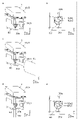
- FIG. 8 is a perspective view showing wiring accessories 1 concerning a modification of an embodiment.
- FIG. 8a is a diagram showing a case where the locking state of the pressing member 60 of the wiring device 1 is released.
- FIG. 8b is an enlarged view of the pressing member 60 and the alignment recess 39a in FIG. 8a.
- 8c is a diagram showing a case where the pressing member 60 of the wiring device 1 is pressed by the tool 91 to be in the locking state.
- 8d is a diagram showing a state in which the wire 90 is inserted into the first insertion hole 37a after the pressing member 60 of the wiring device 1 is pressed and rotated.
- FIG. 8e is an enlarged view of the pressing member 60 and the alignment recess 39a in FIG. 8d.
- the body case 30 is formed with two alignment recesses 39a.
- one alignment concave portion 39a is formed from the second insertion hole 37b of the main body case 30 along the Z-axis plus direction.
- the other positioning recess 39a is formed from the second insertion hole 37b of the main body case 30 along the negative Z-axis direction.
- Each alignment recess 39a may be a groove, a notch, or a simple depression. Therefore, the alignment recess 39a is not limited to a groove shape.
- two positioning recesses 39a are formed in this modification, the number may be one, or three or more.
- the engaging portion 62a of the head 62 has a first engaging recess 62a1 extending along the first direction and a second engaging recess 62a2 intersecting the first direction and extending along the second direction.
- the direction in which the first engagement recess 62a1 extends is orthogonal to the direction in which the second engagement recess 62a2 extends.
- the first engaging recess 62a1 includes the axial center of the pressing shaft portion 61 in the disk-shaped head portion 62, and the outer peripheral edge on the opposite side across the axial center from a predetermined outer peripheral edge of the head portion 62. It extends across to
- the first direction in which the first engaging recess 62a1 extends is substantially parallel to the Z-axis direction.
- the second direction which is the direction in which the second engaging recess 62a2 extends, is arranged to be substantially parallel to the Y-axis direction. That is, when the locking state of the pressing member 60 is released, the pressing member 60 is provided so that the concave portions of the first engaging concave portion 62a1 and the positioning concave portion 39a are aligned (on the same line). Thereby, the operator can easily recognize that the locking state of the pressing member 60 is released.
- the second direction which is the direction in which the second engaging recess 62a2 extends, is arranged to intersect the Y-axis direction. That is, when the pressing member 60 is in the locked state, the pressing member 60 is provided so that the first engaging recess 62a1 and the positioning recess 39a do not align (they do not form the same line). Thereby, the operator can easily recognize that the pressing member 60 is in the locked state.
- the recesses of the first engagement recess 62a1 and the alignment recess 39a are aligned. not.
- the recesses of the first engaging recess 62a1 and the positioning recess 39a may be aligned with each other.
- the terminal device according to this embodiment may not have a transmission member.
- the pressing shaft portion of the pressing member may be disposed in the slit of the terminal and contact the locking spring to directly press and elastically deform the chain spring. That is, unlike the terminal device according to the present embodiment, the pressing force applied to the pressing member is not limited to indirectly pressing the locking spring through the transmission member to elastically deform it. Therefore, the transmission member is not an essential component of the terminal device.
- the transmission member and the pressing member do not overlap the opening surface of the first insertion hole in the Y-axis direction perpendicular to the opening surface. good too. In this case, if the pressing member is in the locked state, the electric wire can be smoothly inserted into the first insertion hole.
- Terminal device 5 Housing 33 Locking portion 37a First insertion hole (insertion hole) 40 terminal 50 locking spring (elastic member) 60 pressing member 61 pressing shaft portion 62 head 62a engaging portion 63 convex portion 70 transmission member 90 electric wire 91 tool
Landscapes
- Details Of Connecting Devices For Male And Female Coupling (AREA)
- Connections Arranged To Contact A Plurality Of Conductors (AREA)
Priority Applications (1)
| Application Number | Priority Date | Filing Date | Title |
|---|---|---|---|
| JP2023503695A JP7541181B2 (ja) | 2021-03-03 | 2022-02-16 | 端子装置 |
Applications Claiming Priority (2)
| Application Number | Priority Date | Filing Date | Title |
|---|---|---|---|
| JP2021033943 | 2021-03-03 | ||
| JP2021-033943 | 2021-03-03 |
Publications (1)
| Publication Number | Publication Date |
|---|---|
| WO2022185912A1 true WO2022185912A1 (ja) | 2022-09-09 |
Family
ID=83154109
Family Applications (1)
| Application Number | Title | Priority Date | Filing Date |
|---|---|---|---|
| PCT/JP2022/006094 Ceased WO2022185912A1 (ja) | 2021-03-03 | 2022-02-16 | 端子装置 |
Country Status (2)
| Country | Link |
|---|---|
| JP (1) | JP7541181B2 (https=) |
| WO (1) | WO2022185912A1 (https=) |
Citations (8)
| Publication number | Priority date | Publication date | Assignee | Title |
|---|---|---|---|---|
| JPS48110685U (https=) * | 1972-03-24 | 1973-12-19 | ||
| DE2826978A1 (de) * | 1977-08-10 | 1979-02-22 | Feller Ag | Schraubenlose elektrische anschlussklemme |
| JPH06168746A (ja) * | 1992-11-30 | 1994-06-14 | Matsushita Electric Works Ltd | 端子装置 |
| JPH11317249A (ja) * | 1998-04-30 | 1999-11-16 | Nitto Electric Works Ltd | 端子装置 |
| DE102008039232A1 (de) * | 2008-08-22 | 2010-02-25 | Phoenix Contact Gmbh & Co. Kg | Elektrische Anschlußklemme |
| US8430674B2 (en) * | 2009-05-26 | 2013-04-30 | Finsecur | Connector with a blade, tool for actuating said connector, kit and fire detector comprising same |
| JP2017091773A (ja) * | 2015-11-09 | 2017-05-25 | 町洋企業股▲ふん▼有限公司 | 係合構造を有する端子台 |
| DE102018126469B3 (de) * | 2018-10-24 | 2020-03-26 | Phoenix Contact Gmbh & Co. Kg | Federanschlusseinrichtung zum Anschließen eines elektrischen Leiters |
Family Cites Families (6)
| Publication number | Priority date | Publication date | Assignee | Title |
|---|---|---|---|---|
| DE3044134C2 (de) * | 1980-11-24 | 1983-09-01 | Siemens AG, 1000 Berlin und 8000 München | Schraubenlose Klemme |
| JP3235175B2 (ja) * | 1991-04-26 | 2001-12-04 | 松下電工株式会社 | 端子装置 |
| US6854999B2 (en) | 2002-07-17 | 2005-02-15 | Tyco Electronics Corporation | Anti-overstress electrical connector |
| DE202013100740U1 (de) * | 2013-02-19 | 2013-03-08 | Weidmüller Interface GmbH & Co. KG | Federkraftklemme für Leiter |
| DE202017103185U1 (de) | 2016-05-30 | 2017-09-01 | Weidmüller Interface GmbH & Co. KG | Federkraftklemme für Leiter |
| JP7316291B2 (ja) | 2018-03-13 | 2023-07-27 | ヴァイトミュラー インターフェイス ゲゼルシャフト ミット ベシュレンクテル ハフツング ウント コンパニー コマンデイトゲゼルシャフト | 導電体用ばね力端子 |
-
2022
- 2022-02-16 WO PCT/JP2022/006094 patent/WO2022185912A1/ja not_active Ceased
- 2022-02-16 JP JP2023503695A patent/JP7541181B2/ja active Active
Patent Citations (8)
| Publication number | Priority date | Publication date | Assignee | Title |
|---|---|---|---|---|
| JPS48110685U (https=) * | 1972-03-24 | 1973-12-19 | ||
| DE2826978A1 (de) * | 1977-08-10 | 1979-02-22 | Feller Ag | Schraubenlose elektrische anschlussklemme |
| JPH06168746A (ja) * | 1992-11-30 | 1994-06-14 | Matsushita Electric Works Ltd | 端子装置 |
| JPH11317249A (ja) * | 1998-04-30 | 1999-11-16 | Nitto Electric Works Ltd | 端子装置 |
| DE102008039232A1 (de) * | 2008-08-22 | 2010-02-25 | Phoenix Contact Gmbh & Co. Kg | Elektrische Anschlußklemme |
| US8430674B2 (en) * | 2009-05-26 | 2013-04-30 | Finsecur | Connector with a blade, tool for actuating said connector, kit and fire detector comprising same |
| JP2017091773A (ja) * | 2015-11-09 | 2017-05-25 | 町洋企業股▲ふん▼有限公司 | 係合構造を有する端子台 |
| DE102018126469B3 (de) * | 2018-10-24 | 2020-03-26 | Phoenix Contact Gmbh & Co. Kg | Federanschlusseinrichtung zum Anschließen eines elektrischen Leiters |
Also Published As
| Publication number | Publication date |
|---|---|
| JPWO2022185912A1 (https=) | 2022-09-09 |
| JP7541181B2 (ja) | 2024-08-27 |
Similar Documents
| Publication | Publication Date | Title |
|---|---|---|
| CA2613658C (en) | Optical connector excellent in maintenance of a connected state | |
| KR101886954B1 (ko) | 커넥터 | |
| JP6007498B2 (ja) | 操作スイッチ | |
| JP4683577B2 (ja) | ロック解除装置及びコネクタ装置 | |
| JP2017228442A (ja) | コネクタ | |
| WO2022185912A1 (ja) | 端子装置 | |
| GB2393592A (en) | Connector with terminal retainer | |
| CN111048938B (zh) | 连接器 | |
| WO2022185911A1 (ja) | 端子装置 | |
| TWI505573B (zh) | Electrical connector | |
| JP4247920B2 (ja) | レバーコネクタ | |
| WO2019106932A1 (ja) | 電池パック及び電池パックを用いた電気機器 | |
| JP3622942B2 (ja) | 配線ダクト用プラグ | |
| KR20100022841A (ko) | 커넥터 | |
| JP4052171B2 (ja) | 速結端子装置 | |
| JP2006073330A (ja) | レバー嵌合式コネクタ | |
| CN219018020U (zh) | 接线端子和电源 | |
| JP7642488B2 (ja) | 電子機器 | |
| JP4404603B2 (ja) | ロックツマミ付パック電池 | |
| JPH0968343A (ja) | 電気機器のハウジング構造 | |
| JP2020115573A (ja) | Usbコンセント | |
| WO2025057642A1 (ja) | 端子構造及び配線器具 | |
| CN223566802U (zh) | 电池仓结构和跟踪仪 | |
| JP3637845B2 (ja) | 配線器具 | |
| TR2023010289T2 (tr) | Terminal cihazı. |
Legal Events
| Date | Code | Title | Description |
|---|---|---|---|
| 121 | Ep: the epo has been informed by wipo that ep was designated in this application |
Ref document number: 22762969 Country of ref document: EP Kind code of ref document: A1 |
|
| ENP | Entry into the national phase |
Ref document number: 2023503695 Country of ref document: JP Kind code of ref document: A |
|
| WWE | Wipo information: entry into national phase |
Ref document number: 2023/010294 Country of ref document: TR |
|
| WWE | Wipo information: entry into national phase |
Ref document number: 2301005249 Country of ref document: TH |
|
| NENP | Non-entry into the national phase |
Ref country code: DE |
|
| 122 | Ep: pct application non-entry in european phase |
Ref document number: 22762969 Country of ref document: EP Kind code of ref document: A1 |