WO2022185798A1 - 内視鏡 - Google Patents
内視鏡 Download PDFInfo
- Publication number
- WO2022185798A1 WO2022185798A1 PCT/JP2022/002874 JP2022002874W WO2022185798A1 WO 2022185798 A1 WO2022185798 A1 WO 2022185798A1 JP 2022002874 W JP2022002874 W JP 2022002874W WO 2022185798 A1 WO2022185798 A1 WO 2022185798A1
- Authority
- WO
- WIPO (PCT)
- Prior art keywords
- rotation
- stand
- operating lever
- range
- endoscope
- Prior art date
- Legal status (The legal status is an assumption and is not a legal conclusion. Google has not performed a legal analysis and makes no representation as to the accuracy of the status listed.)
- Ceased
Links
Images




Classifications
-
- A—HUMAN NECESSITIES
- A61—MEDICAL OR VETERINARY SCIENCE; HYGIENE
- A61B—DIAGNOSIS; SURGERY; IDENTIFICATION
- A61B1/00—Instruments for performing medical examinations of the interior of cavities or tubes of the body by visual or photographical inspection, e.g. endoscopes; Illuminating arrangements therefor
- A61B1/00064—Constructional details of the endoscope body
- A61B1/00071—Insertion part of the endoscope body
- A61B1/0008—Insertion part of the endoscope body characterised by distal tip features
- A61B1/00087—Tools
-
- A—HUMAN NECESSITIES
- A61—MEDICAL OR VETERINARY SCIENCE; HYGIENE
- A61B—DIAGNOSIS; SURGERY; IDENTIFICATION
- A61B1/00—Instruments for performing medical examinations of the interior of cavities or tubes of the body by visual or photographical inspection, e.g. endoscopes; Illuminating arrangements therefor
- A61B1/00064—Constructional details of the endoscope body
- A61B1/00066—Proximal part of endoscope body, e.g. handles
-
- A—HUMAN NECESSITIES
- A61—MEDICAL OR VETERINARY SCIENCE; HYGIENE
- A61B—DIAGNOSIS; SURGERY; IDENTIFICATION
- A61B1/00—Instruments for performing medical examinations of the interior of cavities or tubes of the body by visual or photographical inspection, e.g. endoscopes; Illuminating arrangements therefor
- A61B1/00064—Constructional details of the endoscope body
- A61B1/00071—Insertion part of the endoscope body
- A61B1/0008—Insertion part of the endoscope body characterised by distal tip features
- A61B1/00098—Deflecting means for inserted tools
-
- A—HUMAN NECESSITIES
- A61—MEDICAL OR VETERINARY SCIENCE; HYGIENE
- A61B—DIAGNOSIS; SURGERY; IDENTIFICATION
- A61B1/00—Instruments for performing medical examinations of the interior of cavities or tubes of the body by visual or photographical inspection, e.g. endoscopes; Illuminating arrangements therefor
- A61B1/012—Instruments for performing medical examinations of the interior of cavities or tubes of the body by visual or photographical inspection, e.g. endoscopes; Illuminating arrangements therefor characterised by internal passages or accessories therefor
- A61B1/018—Instruments for performing medical examinations of the interior of cavities or tubes of the body by visual or photographical inspection, e.g. endoscopes; Illuminating arrangements therefor characterised by internal passages or accessories therefor for receiving instruments
-
- A—HUMAN NECESSITIES
- A61—MEDICAL OR VETERINARY SCIENCE; HYGIENE
- A61B—DIAGNOSIS; SURGERY; IDENTIFICATION
- A61B1/00—Instruments for performing medical examinations of the interior of cavities or tubes of the body by visual or photographical inspection, e.g. endoscopes; Illuminating arrangements therefor
- A61B1/04—Instruments for performing medical examinations of the interior of cavities or tubes of the body by visual or photographical inspection, e.g. endoscopes; Illuminating arrangements therefor combined with photographic or television appliances
- A61B1/042—Instruments for performing medical examinations of the interior of cavities or tubes of the body by visual or photographical inspection, e.g. endoscopes; Illuminating arrangements therefor combined with photographic or television appliances characterised by a proximal camera, e.g. a CCD camera
-
- G—PHYSICS
- G02—OPTICS
- G02B—OPTICAL ELEMENTS, SYSTEMS OR APPARATUS
- G02B23/00—Telescopes, e.g. binoculars; Periscopes; Instruments for viewing the inside of hollow bodies; Viewfinders; Optical aiming or sighting devices
- G02B23/24—Instruments or systems for viewing the inside of hollow bodies, e.g. fibrescopes
Definitions
- the present invention relates to an endoscope that allows the user to select the rotation range of the stand operating lever according to his or her preference.
- a treatment instrument stand provided at the distal end of an insertion section is connected to a stand-up table operation lever of an operation section, and the stand-up table is operated by rotating the stand-up table operation lever.
- An endoscope is known that changes its posture and changes the projection direction of a treatment instrument.
- Some rotation mechanisms linked to the stand operating lever and the stand have a function to restrict the rotation of the stand, thereby restricting the range of rotation of the stand.
- a stopper portion is provided on a rotating drum that is connected to a stand operating lever to regulate the rotation range of the stand.
- the rotation range of the standing table is restricted by providing a rotation restricting member that rotates coaxially with the standing table.
- the present invention has been made in view of such circumstances, and an object of the present invention is to provide an endoscope in which the rotation range of the stand operating lever can be selected according to the user's preference.
- the present invention is intended to solve the above problems, and the endoscope of the present invention comprises a bending operation member attached to the main body of the operation section, and a device for erecting the treatment instrument provided at the distal end of the insertion section.
- An endoscope including an erector operation lever for displacing the erection angle of the treatment instrument erector, wherein the erector operation lever has a finger hook portion inside which a rotation restricting member is provided. and the outer peripheral surface of the main body of the operating portion, the rotation of the stand operating lever is restricted.
- the range of rotation of the treatment instrument stand changes according to the range of rotation of the stand operating lever.
- the range of rotation of the treatment instrument stand is changed by changing the position or shape of the rotation restricting member.
- the range of rotation of the treatment instrument stand changes as the height in the direction perpendicular to the installation surface of the rotation restricting member or the width in the direction horizontal to the installation surface changes.
- the finger hook In a state in which the bending operation member and the stand-up operation lever are attached to the main body of the operation unit, the finger hook can be attached and detached. It is preferable that the range of rotation of the treatment instrument stand is changed.
- FIG. 1 is an overall view of an endoscope according to the present invention; FIG. It is the top view which expanded the operation part of the endoscope.
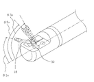
- FIG. 4 is a perspective view for explaining the rotation range of the standing base;
- FIG. 3 is a schematic diagram for explaining an erecting table rotating mechanism;
- FIG. 4 is an exploded view for explaining an operating member attached to the operating portion of the endoscope; It is a perspective view explaining an erection board operating lever.
- FIG. 4 is a schematic diagram illustrating a rotation range of an erector operating lever;
- FIG. 11 is a schematic diagram illustrating the rotation range of the stand operating lever when the height of the rotation restricting member is changed;
- FIG. 10 is a schematic diagram comparing the rotation ranges of the stand operating levers having different rotation ranges;
- FIG. 8 is an explanatory diagram comparing a plurality of different rotation ranges of the stand when using stand-up operation levers with different rotation ranges;
- FIG. 10 is a schematic diagram for explaining the rotation range of the stand operating lever when the width of the rotation restricting member is changed;
- FIG. 10 is an explanatory diagram of a stand operating lever with a detachable finger hanging member;
- an endoscope 10 is connected to a grip portion 11 gripped by a user, an operation portion 12 for performing various operations, an insertion portion 13 to be inserted into a subject, and a connection portion 15 .
- It has a universal code 14 that The endoscope 10 includes a lighting device (not shown) that supplies illumination light to the endoscope 10 via a universal cord 14, and a processor device (not shown) that executes various processes according to the operation of the operation unit 12. (not shown) are connected.
- the insertion portion 13 is connected to a distal end portion 13a, a bending portion 13b, and a flexible portion 13c in this order from the distal end side to the proximal end side.
- the endoscope 10 is, for example, a side-viewing endoscope such as a duodenoscope, and is provided with a treatment instrument insertion opening 17 for inserting a treatment instrument 18 used when performing medical treatment such as treatment and examination. .
- the inserted treatment instrument 18 passes through an insertion path provided inside the insertion portion 13 from the treatment instrument insertion port 17 to the distal end portion 13a, protrudes from the distal end portion 13a, and is used for various medical treatments.
- the operation section 12 includes a vertical angle knob 21 for bending the bending section 13b in the vertical direction and a horizontal angle knob 22 for bending the bending section 13b in the horizontal direction. It has a vertical lock lever 23 and a horizontal lock knob 24 for locking or unlocking the rotation of the knob.
- the bending portion 13b is bent and the tip portion 13a is oriented in a desired direction.
- the vertical lock lever 23 and the horizontal lock knob 24 are rotated as appropriate.
- a plurality of operation buttons 25 are provided on the outer peripheral surface 41a of the main body 41 of the operation unit 12 for executing various processes of the endoscope in cooperation with the processor device.
- the direction indicated by arrow x is the longitudinal direction of the operating portion 12, and the direction indicated by arrow y is the width direction of the operating portion 12.
- the longitudinal direction is the vertical direction when the user normally holds the endoscope 10
- the width direction is the direction orthogonal to the longitudinal direction.
- upward refers to the direction toward the bending operation member side of the main body 41 (from the back side to the front side in FIG. 2), and the opposite direction is referred to as downward.
- the operating section 12 is provided with a stand operating lever 31 .
- the erector operating lever 31 includes a treatment instrument erector 32 (hereinafter simply referred to as an erector) provided at the distal end portion 13a shown in FIG.
- an erector By rotating the stand operating lever 31, the stand 32 is changed from the lying posture to the standing posture, or from the standing posture to the lying posture by the standing stand rotating mechanism 40, which will be described later.
- the treatment instrument 18 protrudes from the distal end portion 13a along the guide surface 32a of the stand 32, and the direction of protrusion changes as the posture of the stand 32 changes.
- FIG. 4 is a schematic diagram for explaining the standing table rotating mechanism 40.
- the standing table rotating mechanism 40 has a rotating member 42 , a crank member 45 connected to the rotating member 42 , and a slider 46 connected to the crank member 45 .
- the slider 46 is connected by a traction wire 47 to a stand-up rotation lever 33 for rotating the stand-up 32 .
- the crank member 45 is a member that converts rotational motion of the rotating member 42 into linear motion of the slider 46 .
- the stand 32 is connected so that the angle of the stand 32 changes when the stand operating lever 31 rotates.
- the raising table operating lever 31 by rotating the raising table operating lever 31, the pulling wire 47 connected to the rotating member 42 is pushed and pulled, thereby moving the standing table.
- the posture of the stand 32 changes. For example, as shown in FIG. 4, when the stand operating lever 31 is rotated in the left rotation direction (rotating direction R) as indicated by the arrow, the traction wire 47 is pulled and the stand 32 is rotated in the standing posture direction. move.
- the rotation range of the stand-up operating lever 31 and the rotation range of the stand-up table 32 correspond to each other. configured to rotate within.
- the stand-up rotation mechanism 40 may be configured such that the stand-up rotation lever 33 is omitted and the pulling wire 47 and the stand-up 32 are directly connected.
- each bending operation member and the raising table operation lever 31 are arranged in order from the outside with respect to the same rotation shaft 51 with respect to the main body portion 41 of the operation portion 12, the left and right lock knobs 24 and the left and right angle levers.
- a knob 22, an up/down angle knob 21, an up/down lock lever 23, and a stand-up operation lever 31 are stacked and attached.
- the raising table operating lever 31 is attached so that the attachment portion (not shown) provided at the center of each bending operation member and the raising table operating lever 31 is inserted into the rotating shaft 51 .
- the vertical lock lever 23, the vertical angle knob 21, the horizontal angle knob 22, and the horizontal lock knob 24 are attached in this order.
- the bending operation member and the stand operation lever 31 are preferably detachable from the main body 41 .
- the stand operating lever 31 includes an attachment member 34 consisting of an annular connecting portion 34a, an L-shaped arm portion 34b (see FIG. 11) connected to the connecting portion 34a, and a finger hook portion 35. consists of The finger hook portion 35 is fixed to the arm portion 34b with a screw (not shown) or the like to the mounting member 34.
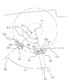
- Rotation restricting members 35a and 35b are provided inside the finger hook portion 35 on both sides in the width direction.
- the rotation restricting member 35a is attached to the main body portion 41, and when the raising table operating lever 31 is rotated, the rotation restricting member 35a is attached to the main body at the rotation start side or the rotation end side (see FIG. 7). It abuts on the outer peripheral surface 41a (see FIG. 5) of the portion 41 and regulates the rotation range of the stand operating lever 31.
- FIG. 5 the outer peripheral surface 41a
- FIG. 7 is a schematic diagram for explaining the rotation range of the stand operating lever 31 having rotation restricting members 35a and 35b of height H1.
- the height of the rotation restricting members 35a and 35b is the dimension in the direction perpendicular to the installation surface when the rotation restricting members 35a and 35b are provided on the finger hook portion 35.
- the standing table operating lever 31 rotates along the direction of the arrow R around the rotating shaft 51 .
- the angle between the straight line shown by the broken line along the longitudinal direction passing through the rotation shaft 51 and the center line shown by the one-dot chain line of the stand operating lever 31 is defined as ⁇ , and the angle ⁇ is appropriately suffixed for explanation.
- ⁇ The angle between the straight line shown by the broken line along the longitudinal direction passing through the rotation shaft 51 and the center line shown by the one-dot chain line of the stand operating lever 31.
- the rotating range of the standing table operating lever 31 is restricted, the rotating range of the standing table 32 is also restricted.
- the posture of the stand 32 is the lowest angle ⁇ at the angle ⁇ 1a.
- the stand operating lever 31 is at the rotation end position R2 at the angle ⁇ 2, the stand 32 is in the maximum standing posture at the maximum angle ⁇ , which is the angle ⁇ 2a.
- the endoscope 10 has a plurality of stand-up table operating levers 31 with different positions or shapes of the rotation restricting members 35a.
- the rotation range of the stand 31 can be easily regulated, and the rotation range of the stand 32 can be selected according to the user's preference and the content of the medical treatment.
- the rotation regulating member 35b on the end of rotation of the finger hook portion 35 of the stand operating lever 31 has a height H2 along the direction facing the body portion 41 that is equal to the rotation regulating member 35b shown in FIG. It is formed higher than the member 35b (height H1). Therefore, the raising table operating lever 31 shown in FIG.
- the rotation restricting members 35a and 35b mean that not only are the heights different as described above, but also the widths are different, and the shapes of the rotation restricting members 35a and 35b when viewed from the cross-sectional direction are circular. Instead, it means different things like triangles and squares.
- the contact surfaces of the rotation restricting members 35a and 35b of the finger hook portion 35 that come into contact with the outer peripheral surface 41a of the body portion 41 will not rotate. may be different with respect to the direction of .
- the width of the rotation restricting members 35a and 35b is the dimension in the direction horizontal to the installation surface when the rotation restricting members 35a and 35b are provided on the finger hook portion 35.
- FIG. 9 is an explanatory diagram comparing the rotation range of the raising table operating lever 31 of FIG. 7 and the rotating range of the raising table operating lever 31 of FIG. 7 rotates within a range from angle ⁇ 1 to ⁇ 2, and the rotation range of the raising table operating lever 31 in FIG. It can be understood that ⁇ rotates within a range from ⁇ 1 to ⁇ 3.
- FIG. 10 shows the difference in the rotation range of the standing table 32 between the standing table operating lever 31 of FIG. 7 and the standing table operating lever 31 of FIG. Referring to FIG. 2, when the standing table operating lever 31 is rotated from left to right in FIG. 2, the standing table 32 rotates in the standing direction. 7, the maximum angle .theta. In this manner, the user can select the rotation range of the erector 32 of the erector operating lever 31 according to the user's preference and the contents of the medical treatment.
- the widths of the rotation restricting members 35a and 35b may be varied. As shown in FIG. 11, the rotation restricting member 35a on the rotation start end side has a width W1, but the rotation restriction member 35b on the rotation end side has a width W2 that is longer than the width W1. Therefore, the rotation end position R4 of the raising table operating lever 31 in FIG. 11 is positioned before the rotation end position R2 of the raising table operating lever 31 in FIG. At this time, the stand operating lever 31 rotates within the range of angle ⁇ 1 to angle ⁇ 4. In this manner, the rotation range of the raising table operating lever 31 can also be restricted by changing the width of the rotation restricting members 35a and 35b instead of changing the height.
- the raising table operating lever 31 of the first embodiment and the second embodiment fixes the mounting member 34 and the finger hook portion 35 with screws or the like, and when the raising table operating lever 31 is replaced, it is positioned above the raising table operating lever 31. It is necessary to remove the bending operation member such as the up/down angle knob 21 that is attached.
- the erector operating lever 31 of the third embodiment has a finger hook 35 that is detachable from the mounting member 34 .
- the erector operating lever 31 of the present embodiment is provided with a fitting groove portion 36a and a T-shaped fitting projection portion 36b on the mounting member 34. As shown in FIG.
- the finger hook portion 35 is provided with a fitting protrusion 37a that fits into the fitting groove 36a and a fitting recess 37b that fits into the fitting projection 36b.
- the finger hook 35 is not completely fixed like it is fixed with a screw, but when the raising table operating lever 31 is rotated, it is usually pressed downward, so that the raising table operating lever 31 rotates. If the finger hook portion 35 is fixed to the mounting member 34 in the circumferential direction and the radial direction, no inconvenience will occur. With this configuration, the finger hook portion 35 of the raising table operating lever 31 can be replaced without removing the bending operation member, and the user can easily replace the raising table operating lever 31 with a desired rotation range. It becomes possible to
- the finger hooking portion 35 has a pair of rotation restricting members 35a and 35b on both sides of the inner surface of the finger hooking portion 35, but it is provided only on one side.
- the rotation regulating member 35a on the rotation starting end side of the stand operating lever 31 is provided, the rotation on the starting end side can be regulated, and only the rotation regulating member 35b on the rotation end side can be provided. If it has, it is possible to regulate the rotation of the rotation end side.
- FIG. 8 only the rotation restricting member 35b on the rotation end side is changed, but only the rotation restriction member 35a on the rotation start end side may be changed.
- the shape and arrangement of the movement restricting member 35b can be changed as appropriate.
- the shape and arrangement of the rotation restricting members 35a and 35b are determined in accordance with the intended use, and a plurality of the raising table operating levers 31 are provided. , the user can select and use the stand operating lever 31 most suitable for medical treatment.
Landscapes
- Health & Medical Sciences (AREA)
- Life Sciences & Earth Sciences (AREA)
- Surgery (AREA)
- Physics & Mathematics (AREA)
- Optics & Photonics (AREA)
- Biomedical Technology (AREA)
- Medical Informatics (AREA)
- Radiology & Medical Imaging (AREA)
- Nuclear Medicine, Radiotherapy & Molecular Imaging (AREA)
- Engineering & Computer Science (AREA)
- Biophysics (AREA)
- Heart & Thoracic Surgery (AREA)
- Pathology (AREA)
- Molecular Biology (AREA)
- Animal Behavior & Ethology (AREA)
- General Health & Medical Sciences (AREA)
- Public Health (AREA)
- Veterinary Medicine (AREA)
- Astronomy & Astrophysics (AREA)
- General Physics & Mathematics (AREA)
- Endoscopes (AREA)
Priority Applications (2)
| Application Number | Priority Date | Filing Date | Title |
|---|---|---|---|
| JP2023503637A JP7733100B2 (ja) | 2021-03-03 | 2022-01-26 | 内視鏡 |
| US18/459,437 US20230404368A1 (en) | 2021-03-03 | 2023-09-01 | Endoscope |
Applications Claiming Priority (2)
| Application Number | Priority Date | Filing Date | Title |
|---|---|---|---|
| JP2021033545 | 2021-03-03 | ||
| JP2021-033545 | 2021-03-03 |
Related Child Applications (1)
| Application Number | Title | Priority Date | Filing Date |
|---|---|---|---|
| US18/459,437 Continuation US20230404368A1 (en) | 2021-03-03 | 2023-09-01 | Endoscope |
Publications (1)
| Publication Number | Publication Date |
|---|---|
| WO2022185798A1 true WO2022185798A1 (ja) | 2022-09-09 |
Family
ID=83154971
Family Applications (1)
| Application Number | Title | Priority Date | Filing Date |
|---|---|---|---|
| PCT/JP2022/002874 Ceased WO2022185798A1 (ja) | 2021-03-03 | 2022-01-26 | 内視鏡 |
Country Status (3)
| Country | Link |
|---|---|
| US (1) | US20230404368A1 (https=) |
| JP (1) | JP7733100B2 (https=) |
| WO (1) | WO2022185798A1 (https=) |
Families Citing this family (1)
| Publication number | Priority date | Publication date | Assignee | Title |
|---|---|---|---|---|
| USD1066659S1 (en) * | 2021-09-24 | 2025-03-11 | Adaptivendo Llc | Endoscope handle |
Citations (3)
| Publication number | Priority date | Publication date | Assignee | Title |
|---|---|---|---|---|
| JPH05115431A (ja) * | 1991-10-29 | 1993-05-14 | Asahi Optical Co Ltd | 内視鏡の処置具起上装置及びその組立方法 |
| JP2016067771A (ja) * | 2014-09-30 | 2016-05-09 | 富士フイルム株式会社 | 内視鏡装置 |
| JP2018086271A (ja) * | 2017-12-27 | 2018-06-07 | 富士フイルム株式会社 | 内視鏡 |
Family Cites Families (4)
| Publication number | Priority date | Publication date | Assignee | Title |
|---|---|---|---|---|
| WO2013106444A1 (en) * | 2012-01-10 | 2013-07-18 | Boston Scientific Scimed, Inc. | A steerable medical device having an imaging system |
| WO2019146329A1 (ja) * | 2018-01-29 | 2019-08-01 | 富士フイルム株式会社 | 内視鏡 |
| US20240156334A1 (en) * | 2022-11-15 | 2024-05-16 | Olympus Medical Systems Corp. | Endoscope bending operation mechanism and endoscope |
| JP2024114583A (ja) * | 2023-02-10 | 2024-08-23 | オリンパスメディカルシステムズ株式会社 | 内視鏡 |
-
2022
- 2022-01-26 WO PCT/JP2022/002874 patent/WO2022185798A1/ja not_active Ceased
- 2022-01-26 JP JP2023503637A patent/JP7733100B2/ja active Active
-
2023
- 2023-09-01 US US18/459,437 patent/US20230404368A1/en active Pending
Patent Citations (3)
| Publication number | Priority date | Publication date | Assignee | Title |
|---|---|---|---|---|
| JPH05115431A (ja) * | 1991-10-29 | 1993-05-14 | Asahi Optical Co Ltd | 内視鏡の処置具起上装置及びその組立方法 |
| JP2016067771A (ja) * | 2014-09-30 | 2016-05-09 | 富士フイルム株式会社 | 内視鏡装置 |
| JP2018086271A (ja) * | 2017-12-27 | 2018-06-07 | 富士フイルム株式会社 | 内視鏡 |
Also Published As
| Publication number | Publication date |
|---|---|
| US20230404368A1 (en) | 2023-12-21 |
| JPWO2022185798A1 (https=) | 2022-09-09 |
| JP7733100B2 (ja) | 2025-09-02 |
Similar Documents
| Publication | Publication Date | Title |
|---|---|---|
| JP5347084B1 (ja) | 内視鏡の湾曲操作装置 | |
| JP4287354B2 (ja) | 手術器具 | |
| US8961402B2 (en) | Endoscope | |
| JP5192098B2 (ja) | 内視鏡 | |
| EP1757217A1 (en) | Endoscope and curve control assist member for endoscope | |
| CN103068296A (zh) | 线引导构件 | |
| CN114760902A (zh) | 插入设备的弯曲操作机构 | |
| EP3192426A1 (en) | Bending operation device and endoscope | |
| WO2022185798A1 (ja) | 内視鏡 | |
| JP3255761B2 (ja) | 内視鏡 | |
| JP7349654B2 (ja) | 内視鏡処置具の進退補助具 | |
| WO2022259549A1 (ja) | 先端カバーおよび内視鏡装置 | |
| JPWO2022185798A5 (https=) | ||
| JP7145982B2 (ja) | 内視鏡 | |
| WO2022185799A1 (ja) | 内視鏡 | |
| JP7822956B2 (ja) | 内視鏡処置具、及び内視鏡装置 | |
| JP6850411B2 (ja) | 持針器 | |
| JP7744927B2 (ja) | 内視鏡処置具、及び内視鏡装置 | |
| EP4458285A1 (en) | Surgical instrument | |
| JP6839548B2 (ja) | 内視鏡 | |
| JP2006110053A (ja) | 内視鏡と内視鏡システム | |
| JP4030807B2 (ja) | 外科用処置具 | |
| JPWO2017145431A1 (ja) | 内視鏡 | |
| JP2025156215A (ja) | 内視鏡の補助装置 | |
| JP2005198950A (ja) | 内視鏡の湾曲操作装置 |
Legal Events
| Date | Code | Title | Description |
|---|---|---|---|
| 121 | Ep: the epo has been informed by wipo that ep was designated in this application |
Ref document number: 22762857 Country of ref document: EP Kind code of ref document: A1 |
|
| WWE | Wipo information: entry into national phase |
Ref document number: 2023503637 Country of ref document: JP |
|
| NENP | Non-entry into the national phase |
Ref country code: DE |
|
| 122 | Ep: pct application non-entry in european phase |
Ref document number: 22762857 Country of ref document: EP Kind code of ref document: A1 |