WO2022181607A1 - 固体電解コンデンサおよびその製造方法 - Google Patents
固体電解コンデンサおよびその製造方法 Download PDFInfo
- Publication number
- WO2022181607A1 WO2022181607A1 PCT/JP2022/007215 JP2022007215W WO2022181607A1 WO 2022181607 A1 WO2022181607 A1 WO 2022181607A1 JP 2022007215 W JP2022007215 W JP 2022007215W WO 2022181607 A1 WO2022181607 A1 WO 2022181607A1
- Authority
- WO
- WIPO (PCT)
- Prior art keywords
- insulating
- insulating region
- anode foil
- main surface
- electrolytic capacitor
- Prior art date
- Legal status (The legal status is an assumption and is not a legal conclusion. Google has not performed a legal analysis and makes no representation as to the accuracy of the status listed.)
- Ceased
Links
Images

Classifications
-
- H—ELECTRICITY
- H01—ELECTRIC ELEMENTS
- H01G—CAPACITORS; CAPACITORS, RECTIFIERS, DETECTORS, SWITCHING DEVICES, LIGHT-SENSITIVE OR TEMPERATURE-SENSITIVE DEVICES OF THE ELECTROLYTIC TYPE
- H01G9/00—Electrolytic capacitors, rectifiers, detectors, switching devices, light-sensitive or temperature-sensitive devices; Processes of their manufacture
- H01G9/15—Solid electrolytic capacitors
-
- H—ELECTRICITY
- H01—ELECTRIC ELEMENTS
- H01G—CAPACITORS; CAPACITORS, RECTIFIERS, DETECTORS, SWITCHING DEVICES, LIGHT-SENSITIVE OR TEMPERATURE-SENSITIVE DEVICES OF THE ELECTROLYTIC TYPE
- H01G9/00—Electrolytic capacitors, rectifiers, detectors, switching devices, light-sensitive or temperature-sensitive devices; Processes of their manufacture
- H01G9/0029—Processes of manufacture
- H01G9/0036—Formation of the solid electrolyte layer
-
- H—ELECTRICITY
- H01—ELECTRIC ELEMENTS
- H01G—CAPACITORS; CAPACITORS, RECTIFIERS, DETECTORS, SWITCHING DEVICES, LIGHT-SENSITIVE OR TEMPERATURE-SENSITIVE DEVICES OF THE ELECTROLYTIC TYPE
- H01G9/00—Electrolytic capacitors, rectifiers, detectors, switching devices, light-sensitive or temperature-sensitive devices; Processes of their manufacture
- H01G9/004—Details
- H01G9/008—Terminals
- H01G9/012—Terminals specially adapted for solid capacitors
-
- H—ELECTRICITY
- H01—ELECTRIC ELEMENTS
- H01G—CAPACITORS; CAPACITORS, RECTIFIERS, DETECTORS, SWITCHING DEVICES, LIGHT-SENSITIVE OR TEMPERATURE-SENSITIVE DEVICES OF THE ELECTROLYTIC TYPE
- H01G9/00—Electrolytic capacitors, rectifiers, detectors, switching devices, light-sensitive or temperature-sensitive devices; Processes of their manufacture
- H01G9/004—Details
- H01G9/04—Electrodes or formation of dielectric layers thereon
- H01G9/048—Electrodes or formation of dielectric layers thereon characterised by their structure
- H01G9/055—Etched foil electrodes
-
- H—ELECTRICITY
- H01—ELECTRIC ELEMENTS
- H01G—CAPACITORS; CAPACITORS, RECTIFIERS, DETECTORS, SWITCHING DEVICES, LIGHT-SENSITIVE OR TEMPERATURE-SENSITIVE DEVICES OF THE ELECTROLYTIC TYPE
- H01G9/00—Electrolytic capacitors, rectifiers, detectors, switching devices, light-sensitive or temperature-sensitive devices; Processes of their manufacture
- H01G9/0029—Processes of manufacture
-
- H—ELECTRICITY
- H01—ELECTRIC ELEMENTS
- H01G—CAPACITORS; CAPACITORS, RECTIFIERS, DETECTORS, SWITCHING DEVICES, LIGHT-SENSITIVE OR TEMPERATURE-SENSITIVE DEVICES OF THE ELECTROLYTIC TYPE
- H01G9/00—Electrolytic capacitors, rectifiers, detectors, switching devices, light-sensitive or temperature-sensitive devices; Processes of their manufacture
- H01G9/004—Details
- H01G9/022—Electrolytes; Absorbents
- H01G9/025—Solid electrolytes
- H01G9/028—Organic semiconducting electrolytes, e.g. TCNQ
Definitions
- the present disclosure relates to solid electrolytic capacitors and manufacturing methods thereof.
- a solid electrolytic capacitor includes a solid electrolytic capacitor element, an exterior body that seals the solid electrolytic capacitor element, and external electrodes that are electrically connected to the solid electrolytic capacitor element.
- a solid electrolytic capacitor element includes an anode foil, a dielectric layer formed on the surface of the anode foil, and a cathode portion covering at least a portion of the dielectric layer.
- the cathode section includes a solid electrolyte layer containing a conductive polymer covering at least a portion of the dielectric layer.
- a solid electrolyte layer is formed, for example, using a treatment liquid containing a conductive polymer.
- the solid electrolyte layer can also be formed by chemical polymerization or electrolytic polymerization using a polymerization liquid containing a conductive polymer precursor.
- Patent document 1 describes an anodizing process in which the surface of a valve metal is roughened and a dielectric oxide film layer is formed on the surface, and the valve metal is subjected to a conductive process to form a boundary between an anode lead-out portion and a cathode portion.
- a solid electrolytic capacitor includes an anode foil having a porous portion on its surface layer, a dielectric layer covering at least a portion of the porous portion, and a solid layer covering at least a portion of the dielectric layer.
- a capacitor element having an electrolyte layer;
- the anode foil has a first main surface and a second main surface opposite to the first main surface, and a first portion including a first end and not formed with the solid electrolyte layer. , including a second end opposite the first end, and a second portion other than the first portion,
- the capacitor element has a first insulating region on the first main surface side and a second insulating region on the second main surface side between the first end and the second end.
- the water repellency R2 in at least part of the second insulation region is higher than the water repellency R1 in the first insulation region.
- a method for manufacturing a solid electrolytic capacitor according to a second aspect of the present disclosure includes: an anode foil having a porous portion on its surface layer; a dielectric layer covering at least a portion of the porous portion; and at least a portion of the dielectric layer.
- a method for manufacturing a solid electrolytic capacitor including a capacitor element having a solid electrolyte layer covering a The anode foil has a first principal surface and a second principal surface opposite to the first principal surface, and a first portion including a first end and not covered with the solid electrolyte layer.
- the manufacturing method forms a first insulating region on the first main surface side and a second insulating region on the second main surface side between the first end portion and the second end portion. including the step of The water repellency R2 in at least part of the second insulation region is higher than the water repellency R1 in the first insulation region.
- leakage current can be reduced in solid electrolytic capacitors.
- FIG. 1 is a cross-sectional schematic diagram of a solid electrolytic capacitor according to an embodiment of the present disclosure.
- 2 is a cross-sectional view schematically showing a solid electrolytic capacitor element included in the solid electrolytic capacitor of FIG. 1.
- FIG. 1 is a cross-sectional schematic diagram of a solid electrolytic capacitor according to an embodiment of the present disclosure.
- 2 is a cross-sectional view schematically showing a solid electrolytic capacitor element included in the solid electrolytic capacitor of FIG. 1.
- the cathode portion including the solid electrolyte layer is connected to the other end portion of the anode foil. It is formed.
- an insulating portion is provided at the end portion of the anode portion on the cathode portion side or in the vicinity thereof.
- a power feeder power feed tape, etc.
- a polymerization voltage is applied to the power feeder, and the conductive polymer precursor (more specifically, the conductive polymer Polymerization of the conjugated polymer precursor) proceeds to form a solid electrolyte layer containing the conductive polymer.
- One main surface (first main surface) of the anode foil is connected so as to cover most of the insulating portion. Therefore, on the first main surface side, polymerization of the conductive polymer precursor is prevented on the surface of the insulating portion.
- the first insulating region is formed on the first main surface side of the anode foil, and the second insulating region is formed on the second main surface side. Then, the water repellency R2 in at least a part of the second insulation region is made higher than the water repellency R1 in the first insulation region. This makes it difficult for the precursor of the conductive polymer to polymerize on the surface of the second insulating region, thereby suppressing the formation of the solid electrolyte layer. Therefore, leakage current can be reduced. Also, the short-circuit defect rate of the solid electrolytic capacitor can be reduced.
- the water repellency R1 and R2 can be expressed by the static contact angle of water with respect to the material contained in each insulating region. If the insulating region has high water repellency (in other words, the static contact angle of water with respect to the material contained in the insulating region is large), the affinity of the insulating region for the polymerization liquid containing the precursor of the conductive polymer used in the electropolymerization. low wettability. Therefore, it can be said that the water repellency R1 and R2 are indicators that each insulating region repels the polymerization liquid.
- the anode foil has a first end and a second end opposite the first end.
- the solid electrolyte layer is formed on the second end side of the anode foil and not formed on the first end.
- a portion of the anode foil where the solid electrolyte layer is not formed, including the first end portion, is referred to as a first portion.
- the first portion corresponds to the anode portion.
- An anode lead terminal is connected to the first portion.
- a portion of the anode foil other than the first portion is referred to as a second portion.
- the second portion includes a second end.
- the anode foil has a first main surface, which is a pair of main surfaces occupying most of the surface of the anode foil, and a second main surface opposite to the first main surface.
- the anode foil has end faces at the ends of the first principal surface and the second principal surface.
- the first main surface, the second main surface and the end surface form the outline of the anode foil.
- the direction from the first end to the second end of the anode foil is defined as the length direction of the anode foil, and when the main surface of the anode foil is viewed from a direction perpendicular to the main surface, the anode foil
- the direction perpendicular to the length direction of the anode foil is defined as the width direction of the anode foil.
- the width direction of the anode foil is also perpendicular to the thickness direction of the anode foil.
- the direction from the first end to the second end is a direction parallel to a straight line connecting the center of the end surface of the anode foil on the first end side and the center of the end surface on the second end side.
- a solid electrolytic capacitor element included in a solid electrolytic capacitor includes an anode foil having a porous portion on its surface layer, a dielectric layer covering at least a portion of the porous portion, a cathode portion covering at least a portion of the dielectric layer, including.
- the solid electrolytic capacitor element may be simply referred to as a capacitor element.
- the anode foil can include valve action metals, alloys containing valve action metals, compounds containing valve action metals, and the like. These materials may be used singly or in combination of two or more. For example, aluminum, tantalum, niobium, and titanium are preferably used as valve metals.
- the anode foil includes a substrate portion and surface layer porous portions located on both main surface sides of the substrate portion.
- the porous portion may be formed not only on the surface layer of the anode foil but also on portions other than the surface layer, if necessary.
- the anode foil may have the porous portion on the surface layer of at least a part of the second portion, may have the porous portion on the surface layer of the entire second portion, or may have the porous portion on the surface layer of the entire anode foil. good too.
- An anode foil having a porous portion on its surface layer is formed, for example, by roughening the surface of a sheet-like base material (such as a metal foil) containing a valve action metal. Roughening can be performed by, for example, etching treatment (eg, electrolytic etching).
- a dielectric layer is an insulating layer that functions as a dielectric.
- the dielectric layer is formed by anodizing the valve action metal on the surface of the anode foil by chemical conversion treatment or the like.
- the dielectric layer may be formed so as to cover at least part of the porous portion of the anode foil.
- a dielectric layer is usually formed on the surface of the anode foil. Therefore, the dielectric layer is formed along the irregularities on the surface of the anode foil and the inner wall surfaces of the voids in the porous portion.
- the dielectric layer is formed, for example, on at least part of the surface of the second portion of the anode foil.
- a dielectric layer may be formed on at least a part of the surface of the first portion of the anode foil, if necessary.
- the dielectric layer contains an oxide of a valve metal.
- the dielectric layer contains Ta 2 O 5 when tantalum is used as the valve metal, and the dielectric layer contains Al 2 O 3 when aluminum is used as the valve metal.
- the dielectric layer is not limited to these examples, and may be formed of a material that functions as a dielectric.
- the capacitor element has a first insulating region on the first main surface side of the anode foil and a second insulating region on the second main surface side between the first end and the second end of the anode foil. .
- the solid electrolyte layer is electrolyzed in a state in which a power feeder is connected to the first insulating region and the anode foil having the dielectric layer is in contact with (for example, immersed in) a polymerization liquid containing a conductive polymer precursor. It is formed by carrying out polymerization.
- the water repellency R2 in at least part of the second insulation region is higher than the water repellency R1 in the first insulation region.
- the progress of polymerization of the conductive polymer precursor is hindered, and the formation of the solid electrolyte layer is suppressed. Therefore, insulation between the anode part and the cathode part is ensured, and leakage current can be reduced.
- Each of the first insulating region and the second insulating region is preferably provided in a strip shape along the width direction of the anode foil.
- the effect of ensuring insulation between the anode portion and the cathode portion can be enhanced.
- it is preferable that each of the first insulating region and the second insulating region is provided over the entire width direction of the anode foil.
- the width w1 of the first insulating region is, for example, 0.01L or more and 0.3L or less, and may be 0.03L or more and 0.15L or less. When w1 is within such a range, it is easy to connect a power supply, to further easily ensure insulation between the anode portion and the cathode portion on the first main surface side, and to easily ensure a high capacitance.
- L is the length of the anode foil.
- the length L of the anode foil is the length of a straight line connecting the center of the end surface of the anode foil on the first end side and the center of the end surface on the second end side.
- the width w2 of the second insulating region is, for example, 0.01L or more and 0.3L or less, and may be 0.03L or more and 0.15L. When w2 is within such a range, it is easier to secure insulation between the anode portion and the cathode portion on the second main surface side, and in addition, it is easier to secure a high capacitance.
- the widths w1 and w2 of each insulating region are the lengths of each insulating region in the direction along the length direction of the anode foil. Widths w1 and w2 of each insulating region are obtained by measuring the width of each insulating region at arbitrary multiple locations (for example, 10 locations) and averaging them. The width of each insulating region and the length L of the anode foil can be obtained from a cross-sectional image of the solid electrolytic capacitor or capacitor element (for example, a cross-sectional image obtained by a scanning electron microscope).
- a sample (Sample A) obtained by the following procedure can be used to measure the width of the insulating region and the length L of the anode foil.
- a solid electrolytic capacitor is embedded in a hardening resin, and the hardening resin is hardened.
- a cross-section parallel to the thickness direction of the solid electrolyte layer and parallel to the length direction of the capacitor element is exposed by subjecting the cured product to polishing or cross-section polishing.
- the cross section is a cross section that passes through the center of the end face on the first end side and the center of the end face on the second end side of the anode foil.
- Each insulating region may be formed at any position other than the first end and the second end as long as it is between the first end and the second end of the anode foil.
- the second insulating region may overlap at least a portion of the first insulating region.
- each insulating region should be determined according to the design of the capacitor element. From the viewpoint of easily securing connectivity with the anode lead terminal and high capacitance, each insulating region may be provided, for example, at a position of 0.1 L or more and 0.5 L or less from the first end. .1L or more and 0.3L or less may be provided.
- the first insulating region and the second insulating region should be formed on at least the first main surface and the second main surface of the anode foil, respectively.
- An insulating portion (first insulating portion) may be formed on the first main surface side of the anode foil, and the outer surface of the first insulating portion may constitute the first insulating region.
- An insulating portion (second insulating portion) may be formed on the second main surface side of the anode foil, and the outer surface of the second insulating portion may constitute the second insulating region.
- the first insulating part includes, for example, a first insulating material.
- the first insulating region has insulating properties due to the first insulating material.
- the first insulating portion may be formed (for example, in a layered manner) so as to cover the first main surface of the anode foil, or may be included in the porous portion on the first main surface side. may be
- the second insulating part contains an insulating liquid-repellent material.
- the liquid-repellent material has high water repellency and is highly effective in repelling a polymerization liquid containing a conductive polymer precursor. With such a liquid repellent material, the second insulating region exhibits insulating properties and has a high water repellency R2.
- the second insulating portion may be formed (for example, in a layered form) so as to cover the second main surface of the anode foil, or may be included in the porous portion on the second main surface side. may be A portion of the second insulating portion containing an insulating liquid-repellent material is sometimes referred to as a liquid-repellent portion.
- the second insulating part may contain a second insulating material. At least part of the second insulating material in the second insulating portion is covered with the liquid-repellent material. Thereby, the outer surface of the second insulating part constitutes the second insulating region and exhibits a high water repellency R2.
- the second insulating material may be arranged (for example, in a layer) so as to cover the second main surface of the anode foil, or may be included in the porous portion on the second main surface side. may be For example, when the second insulating material is arranged in a layer so as to cover the second main surface, the liquid-repellent material is arranged so as to cover at least part of the layer of the second insulating material.
- the liquid-repellent material may be contained in the porous portion and may be arranged so as to cover the second main surface. may be both.
- a portion of the second insulating portion that does not contain the liquid-repellent material but contains the second insulating material may be referred to as an insulating portion 2A.
- the second insulating portion for example, at least part of the insulating portion 2A is covered with a liquid-repellent portion.
- the porous portion may be compressed, or at least part of the porous portion may be removed, if necessary.
- each insulating region (or each insulating portion) is not particularly limited.
- the electrical resistance value of each insulating portion may be, for example, 1.0 ⁇ 10 12 ⁇ m or more, or 1.0 ⁇ 10 13 ⁇ m or more.
- each of the first insulating material and the second insulating material examples include cured curable materials and thermoplastic resins.
- the first insulating material and the second insulating material may be of the same type or of different types. Since a power supply such as a power supply tape is connected to the first insulating region, it is preferable that the first insulating region have moderate tackiness (adhesiveness).
- moderate tackiness can be obtained in the first insulating region, stably performing electrolytic polymerization, and forming a solid electrolyte layer in the first insulating region. can be restricted.
- the curable material may be either thermosetting or photocurable.
- the curable material includes, for example, a reactive compound and, if necessary, at least one selected from the group consisting of curing agents, curing accelerators, polymerization initiators, catalysts, and additives.
- the curable material may be either of the one-component curing type and the two-component curing type.
- Reactive compounds are compounds that can polymerize or crosslink, for example, by the action of heat or light.
- Curable materials include, for example, phenolic resins, urea resins, melamine resins, unsaturated polyesters, furan resins, epoxy resins, thermosetting polyurethane resins, allyl resins, silicon resins (silicone), curable acrylic resins, thermosetting A polyimide is mentioned.
- Each insulating part may contain one kind of these materials, or may contain two or more kinds in combination. Unsaturated polyester is preferable from the viewpoint of high permeability to the porous part.
- the glass transition point (Tg) of the cured product of the curable material is not particularly limited.
- the Tg of the cured product may be, for example, 100° C. or higher, or 110° C. or higher.
- the Tg of the cured product may be, for example, 400° C. or lower, 350° C. or lower, or 200° C. or lower.
- Tg is determined by, for example, dynamic viscoelasticity measurement (DMA) at a heating rate of 2° C./min and a frequency of 1 Hz.
- DMA dynamic viscoelasticity measurement
- thermoplastic resin engineering plastics are preferable from the viewpoint of being excellent in acid resistance, heat resistance and strength.
- engineering plastics include general purpose engineering plastics and super engineering plastics.
- thermoplastics such as engineering plastics
- thermoplastics include polyesters, polyamides, polycarbonates, polyacetals, polyphenylene ethers, polyphenylene sulfides, polyetheretherketones, polyacryletherketones, polyamides, polyamideimides, polyimides, polyetherimides, polysulfones, poly Includes ether sulfones, polyolefins, and fluoroplastics (such as polyvinylidene fluoride).
- Each insulating part may contain one type of thermoplastic resin, or may contain two or more types in combination.
- Polyamideimide is preferable from the viewpoint of excellent acid resistance and heat resistance.
- liquid-repellent materials include resin materials containing water-repellent groups.
- Hydrophobic groups include hydrocarbon groups and fluorinated hydrocarbon groups.
- Hydrocarbon groups contained in the water-repellent group include aliphatic hydrocarbon groups (such as alkyl groups), alicyclic hydrocarbon groups, and aromatic hydrocarbon groups (such as aryl groups such as phenyl groups).
- resin materials include, but are not limited to, fluororesins, silicone resins, and hydrocarbon resins. From the viewpoint of obtaining high water repellency, the fluororesin is preferably a fluororesin containing perfluoroolefin as a monomer unit.
- fluororesin examples include polytetrafluoroethylene, tetrafluoroethylene-hexafluoropropylene copolymer, tetrafluoroethylene-perfluoroalkyl vinyl ether copolymer, and the like.
- silicone resins include polysiloxanes having water-repellent groups such as alkyl groups or aryl groups in side chains.
- the second insulating portion (or liquid-repellent portion) may contain one type of liquid-repellent material, or may contain two or more types in combination.
- the liquid-repellent part may contain only the liquid-repellent material.
- the liquid-repellent portion is It may contain a liquid material and another resin material.
- Other resin materials include, for example, thermoplastic resins among the materials exemplified for the first insulating material and the second insulating material.
- the liquid-repellent portion may contain one kind of other resin material, or two or more kinds thereof. Polyamideimide is preferable as the other resin material from the viewpoint of excellent acid resistance and heat resistance and excellent affinity with the liquid-repellent material.
- the content of the liquid-repellent material in the liquid-repellent portion is, for example, 0.1% by mass or more, and may be 1% by mass or more or 10% by mass or more.
- the content of the liquid-repellent material in the liquid-repellent portion is 100% by mass or less.
- the water repellency R2 in at least part of the second insulating region is represented by the static contact angle of water with respect to the material (for example, liquid repellent material) included in the second insulating region.
- the water repellency R2 is, for example, 180° or less, and may be 150° or less or 130° or less. When the water repellency R2 is within such a range, the effect of suppressing the formation of the solid electrolyte layer in the second insulating region is further enhanced.
- At least a portion of the second insulating region may be composed of a liquid-repellent material exhibiting water repellency R2.
- the entire second insulating region is composed of the liquid-repellent material exhibiting water repellency R2, it becomes easier to ensure insulation between the anode portion and the cathode portion.
- the second insulating region contains a mixture of a liquid repellent material and another resin material, the static contact angle of water with respect to the mixture corresponds to water repellency R2, and is preferably within the above range.
- the water repellency R1 of the first insulating region is represented by the static contact angle of water with respect to the material (for example, the first insulating material) included in the first insulating region.
- the ratio of water repellency R1 to water repellency R2 is less than 1, may be 0.95 or less, or may be 0.9 or less.
- the water repellency R1 may be 80° or less from the viewpoint of easily ensuring connectivity between the power feeding body and the first insulating region. It may be less than 80°, less than or equal to 75°, or less than 75°.
- Each of the water-repellent R1 and R2 forms a coating using the material contained in the first insulating region (eg, first insulating material) or the material contained in the second insulating region (eg, liquid-repellent material or mixture thereof). and can be measured by the sessile drop method using this coating. More specifically, about 3 ⁇ L of distilled water is dropped on the film under an environment of 23° C. and 50 RH%, and the static contact angle of the water droplet to the film is measured using a contact angle meter. The static contact angle of water droplets is measured five times, and the average value is calculated.
- first insulating region eg, first insulating material
- the material contained in the second insulating region eg, liquid-repellent material or mixture thereof.
- This average value is taken as the static contact angle of water with respect to the material included in the first insulating region (e.g., first insulating material) or the material included in the second insulating region (e.g., liquid-repellent material or mixture thereof).
- Aqueous R1 and R2 respectively.
- As the contact angle meter for example, "DCA-UZ" manufactured by Kyowa Interface Science Co., Ltd. is used.
- the first insulating region is formed on the first main surface side, and the second insulating region is formed on the second main surface side. It is formed on the two main surface sides.
- Each insulating region may be formed such that the water repellency R2 of at least a portion of the second insulating region is higher than the water repellency R1 of the first insulating region.
- the formation of the first insulating region and the formation of the second insulating region may be performed in parallel, and after forming one of the insulating regions, the other insulating region is formed.
- the step of forming the insulating region is performed before the step of forming the solid electrolyte layer.
- the step of forming the insulating region may be performed before the step of forming the dielectric layer on the anode foil, but is usually performed after the step of forming the dielectric layer.
- the first insulating region for example, is provided with a first insulating material (or a precursor thereof) on the first main surface side of the anode foil at a predetermined position between the first end and the second end of the anode foil. and forming a first insulating portion including a first insulating material.
- the outer surface of the formed first insulating portion constitutes the first insulating region.
- the first insulating material (or its precursor) may be applied to the porous portion on the first main surface side.
- the coating may impregnate the porous portion with at least a portion of the first insulating material (or its precursor).
- the application may form a coating of the first insulating material on the first major surface.
- a layered or sheeted first insulating material may be laminated (or transferred) on the first main surface. From the viewpoint of suppressing the formation of the solid electrolyte layer in the porous portion, it is preferable to impregnate the porous portion with the first insulating material (or its precursor).
- the first insulating material (or its precursor) applied to the first main surface of the anode foil is optionally subjected to at least one treatment selected from the group consisting of drying, heating, and light irradiation. you can go
- the precursor of the first insulating material is cured, such as by heating or light irradiation, to form the first insulating material.
- Application of the first insulating material (or its precursor) to the anode foil may be performed in one step or in multiple steps.
- the second insulating region is formed by applying at least a liquid-repellent material to the second main surface side of the anode foil at a predetermined position between the first end and the second end of the anode foil, and applying the liquid-repellent material.
- the liquid-repellent material applied to the anode foil may be subjected to drying treatment or heat treatment, if necessary.
- the second insulating portion may be formed by applying a mixture containing a liquid-repellent material and another resin material to the second main surface of the anode foil.
- the second insulating material Prior to applying the liquid-repellent material to the anode foil, the second insulating material (or its precursor) may be applied to the second main surface side of the anode foil.
- a second insulating portion including an insulating portion 2A containing the second insulating material and a liquid-repellent portion containing the liquid-repellent material is formed.
- at least part of the second insulating material is covered with a liquid-repellent material.
- the liquid-repellent material (and its mixture) and the second insulating material (or its precursor) can be applied to the anode foil in the same manner as the first insulating material (or its precursor).
- the second insulating material (or its precursor) applied to the second main surface of the anode foil is optionally subjected to at least one treatment selected from the group consisting of drying, heating, and light irradiation. you can go
- the precursor of the second insulating material is cured, such as by heating or light irradiation, to form the second insulating material.
- the liquid medium includes a medium that is liquid at room temperature (for example, 20° C. or higher and 35° C. or lower).
- the liquid medium include at least one selected from the group consisting of water and organic solvents.
- the cathode section includes at least a solid electrolyte layer covering at least a portion of the dielectric layer.
- the solid electrolyte layer is formed on the surface of the second portion of the anode foil via the dielectric layer.
- the cathode section usually includes a solid electrolyte layer and a cathode extraction layer covering at least a portion of the solid electrolyte layer. The solid electrolyte layer and the cathode extraction layer are described below.
- the solid electrolyte layer contains a conductive polymer.
- Conductive polymers include, for example, conjugated polymers and dopants.
- the solid electrolyte layer may further contain additives as needed.
- Conjugated polymers include known conjugated polymers used in solid electrolytic capacitors, such as ⁇ -conjugated polymers.
- Conjugated polymers include, for example, polymers having polypyrrole, polythiophene, polyaniline, polyfuran, polyacetylene, polyphenylene, polyphenylenevinylene, polyacene, and polythiophenevinylene as a basic skeleton.
- polymers having a basic skeleton of polypyrrole, polythiophene, or polyaniline are preferred.
- the above polymer may contain at least one type of monomer unit that constitutes the basic skeleton.
- the monomer units also include monomer units having substituents.
- the above polymers include homopolymers and copolymers of two or more monomers.
- polythiophenes include poly(3,4-ethylenedioxythiophene) and the like.
- conjugated polymers preferred are conjugated polymers containing monomer units corresponding to at least one selected from the group consisting of pyrrole compounds, thiophene compounds, and aniline compounds.
- pyrrole compounds include compounds having a pyrrole ring and capable of forming a repeating structure of corresponding monomer units.
- Thiophene compounds include compounds having a thiophene ring and capable of forming a repeating structure of corresponding monomer units. These compounds can be linked at the 2- and 5-positions of the pyrrole or thiophene ring to form a repeating structure of monomeric units.
- aniline compounds include compounds having a benzene ring and at least one (preferably one) amino group bonded to the benzene ring and capable of forming a repeating structure of corresponding monomer units.
- the aniline compound can form a repeating structure of monomer units by connecting, for example, an amino group with a CH group p-positioned to the amino group (a CH group constituting a benzene ring).
- the pyrrole compound may have a substituent at, for example, at least one of the 3- and 4-positions of the pyrrole ring.
- the thiophene compound may have a substituent at, for example, at least one of the 3- and 4-positions of the thiophene ring.
- the 3-position substituent and the 4-position substituent may be linked to form a ring condensed to a pyrrole ring or a thiophene ring.
- the pyrrole compound includes, for example, pyrrole optionally having a substituent at at least one of the 3- and 4-positions.
- the thiophene compounds include, for example, thiophenes optionally having a substituent at at least one of the 3- and 4-positions, alkylenedioxythiophene compounds (C 2-4 alkylenedioxythiophene compounds such as ethylenedioxythiophene compounds, etc. ).
- Alkylenedioxythiophene compounds include those having a substituent on the alkylene group portion.
- Aniline compounds include, for example, anilines which may have a substituent at at least one of the o-position and p-position with respect to the amino group.
- substituents include alkyl groups (C 1-4 alkyl groups such as methyl group and ethyl group), alkoxy groups (C 1-4 alkoxy groups such as methoxy group and ethoxy group), hydroxy groups, hydroxyalkyl groups ( hydroxy C 1-4 alkyl groups such as hydroxymethyl groups) and the like are preferred, but not limited thereto.
- substituents include alkyl groups (C 1-4 alkyl groups such as methyl group and ethyl group), alkoxy groups (C 1-4 alkoxy groups such as methoxy group and ethoxy group), hydroxy groups, hydroxyalkyl groups ( hydroxy C 1-4 alkyl groups such as hydroxymethyl groups) and the like are preferred, but not limited thereto.
- each substituent may be the same or different.
- a conjugated polymer containing at least a monomer unit corresponding to pyrrole, or a conjugated polymer containing at least a monomer unit corresponding to a 3,4-ethylenedioxythiophene compound (such as 3,4-ethylenedioxythiophene (EDOT)) (such as PEDOT) may also be used.
- the conjugated polymer containing at least a monomer unit corresponding to pyrrole may contain only a monomer unit corresponding to pyrrole, and in addition to the monomer unit, a monomer corresponding to a pyrrole compound other than pyrrole (such as pyrrole having a substituent) May contain units.
- a conjugated polymer containing at least a monomer unit corresponding to EDOT may contain only a monomer unit corresponding to EDOT, or may contain, in addition to the monomer unit, a monomer unit corresponding to a thiophene compound other than EDOT.
- the solid electrolyte layer may contain one type of conjugated polymer or may contain two or more types in combination.
- the weight average molecular weight (Mw) of the conjugated polymer is not particularly limited, but is, for example, 1,000 or more and 1,000,000 or less.
- the weight average molecular weight (Mw) is a polystyrene-equivalent value measured by gel permeation chromatography (GPC). GPC is usually measured using a polystyrene gel column and water/methanol (volume ratio 8/2) as a mobile phase.
- dopants include at least one selected from the group consisting of anions and polyanions.
- anions include sulfate ions, nitrate ions, phosphate ions, borate ions, organic sulfonate ions, and carboxylate ions, but are not particularly limited.
- Dopants that generate sulfonate ions include, for example, benzenesulfonic acid, p-toluenesulfonic acid, and naphthalenesulfonic acid.
- polyanions include polymer anions.
- the solid electrolyte layer may contain, for example, a conjugated polymer containing monomer units corresponding to a thiophene compound and a polymer anion.
- polymer anions include polymers having multiple anionic groups. Such polymers include polymers containing monomeric units having anionic groups. Examples of anionic groups include sulfonic acid groups and carboxy groups.
- the anionic group of the dopant may be contained in a free form, an anionic form, or a salt form, or may be contained in a form bound or interacting with the conjugated polymer. .
- anionic group sulfonic acid group
- carboxy group sulfonic acid group
- polymer anions having carboxy groups include, but are not limited to, polyacrylic acid, polymethacrylic acid, and copolymers using at least one of acrylic acid and methacrylic acid.
- polymer anions having a sulfonic acid group include, for example, polymer-type polysulfonic acids such as polyvinylsulfonic acid, polystyrenesulfonic acid (including copolymers and substituents having substituents), and polyallylsulfonic acid. , polyacrylsulfonic acid, polymethacrylsulfonic acid, poly(2-acrylamido-2-methylpropanesulfonic acid), polyisoprene sulfonic acid, polyestersulfonic acid (aromatic polyestersulfonic acid, etc.), phenolsulfonic acid novolac resin. but not limited to these.
- the amount of the dopant contained in the solid electrolyte layer is, for example, 10 to 1000 parts by mass, and may be 20 to 500 parts by mass or 50 to 200 parts by mass with respect to 100 parts by mass of the conjugated polymer.
- the solid electrolyte layer may further contain at least one selected from the group consisting of known additives and known conductive materials other than conductive polymers.
- the conductive material include at least one selected from the group consisting of conductive inorganic materials such as manganese dioxide, and TCNQ complex salts.
- a layer for enhancing adhesion may be interposed between the dielectric layer and the solid electrolyte layer.
- the solid electrolyte layer may be a single layer or may be composed of multiple layers.
- the conductive polymer contained in each layer may be the same or different.
- the dopant contained in each layer may be the same or different.
- the solid electrolyte layer is formed by electrolytic polymerization. Electropolymerization can be performed by applying a polymerization voltage while the anode foil having the dielectric layer is in contact with (for example, immersed in) a polymerization liquid (liquid composition) containing a conductive polymer precursor. . Application of the superimposing voltage is performed via a power supply. A power supply is connected (or attached) to the first insulating region. The power supply is preferably connected (or attached) to the first insulating region so as to cover most of the first insulating region (particularly, the entire width of the anode foil in a strip shape). As a result, formation of the solid electrolyte layer on the first insulating region is suppressed, and the effect of ensuring insulation between the anode portion and the cathode portion is enhanced.
- the liquid composition contains a conductive polymer precursor.
- the conductive polymer precursor includes at least a conjugated polymer precursor and optionally includes a dopant.
- precursors of conjugated polymers include starting monomers for conjugated polymers, oligomers and prepolymers in which a plurality of molecular chains of starting monomers are linked.
- One type of precursor may be used, or two or more types may be used in combination. It is preferable to use at least one kind (especially monomer) selected from the group consisting of monomers and oligomers as the precursor, from the viewpoint of easily obtaining higher orientation of the conjugated polymer.
- a liquid composition usually contains a solvent.
- Solvents include, for example, at least one selected from the group consisting of water and organic solvents.
- a precoat layer containing a conductive material may be formed on the surface of the dielectric layer prior to electrolytic polymerization.
- the liquid composition may optionally contain an oxidizing agent.
- the oxidizing agent may be applied to the anode foil before or after the liquid composition is brought into contact with the anode foil having the dielectric layer.
- oxidizing agents include compounds capable of generating Fe 3+ (ferric sulfate, etc.), persulfates (sodium persulfate, ammonium persulfate, etc.), and hydrogen peroxide.
- the oxidizing agents can be used singly or in combination of two or more.
- the polymerization voltage is, for example, 0.6 V or more and 1.5 V or less, and may be 0.7 V or more and 1 V or less. Note that the polymerization voltage is the electric potential of the power supply with respect to the reference electrode (silver/silver chloride electrode (Ag/Ag + )).
- the temperature for electrolytic polymerization is, for example, 5°C or higher and 60°C or lower, or may be 15°C or higher and 35°C or lower.
- the cathode extraction layer may include at least the first layer that contacts the solid electrolyte layer and covers at least a portion of the solid electrolyte layer, or may include the first layer and the second layer that covers the first layer. good.
- the first layer include a layer containing conductive particles, a metal foil, and the like.
- the conductive particles include, for example, at least one selected from conductive carbon and metal powder.
- the cathode extraction layer may be composed of a layer containing conductive carbon (also referred to as a carbon layer) as the first layer and a layer containing metal powder or metal foil as the second layer. When a metal foil is used as the first layer, the metal foil may constitute the cathode extraction layer.
- Examples of conductive carbon include graphite (artificial graphite, natural graphite, etc.).
- the layer containing metal powder as the second layer can be formed, for example, by laminating a composition containing metal powder on the surface of the first layer.
- a composition containing metal powder such as silver particles and resin (binder resin).
- resin a thermoplastic resin can be used, but it is preferable to use a thermosetting resin such as an imide resin or an epoxy resin.
- the type of metal is not particularly limited. It is preferable to use a valve action metal (aluminum, tantalum, niobium, etc.) or an alloy containing a valve action metal for the metal foil. If necessary, the surface of the metal foil may be roughened. The surface of the metal foil may be provided with a chemical conversion coating, or may be provided with a coating of a metal (dissimilar metal) different from the metal constituting the metal foil (dissimilar metal) or a non-metal coating. Examples of dissimilar metals and non-metals include metals such as titanium and non-metals such as carbon (such as conductive carbon).
- the coating of the dissimilar metal or nonmetal may be used as the first layer, and the metal foil may be used as the second layer.
- a separator When a metal foil is used for the cathode extraction layer, a separator may be arranged between the metal foil and the anode foil.
- the separator is not particularly limited, and for example, a nonwoven fabric containing fibers of cellulose, polyethylene terephthalate, vinylon, polyamide (eg, aromatic polyamide such as aliphatic polyamide and aramid) may be used.
- the solid electrolytic capacitor may be of wound type, chip type or laminated type.
- a solid electrolytic capacitor may include at least one capacitor element, and may include a plurality of capacitor elements.
- a solid electrolytic capacitor may comprise a stack of two or more capacitor elements.
- each capacitor element may be, for example, wound type or laminated type.
- the configuration of the capacitor element may be selected according to the type of solid electrolytic capacitor.
- one end of the cathode lead terminal is electrically connected to the cathode extraction layer.
- One end of the anode lead terminal is electrically connected to the first portion of the anode foil.
- the other end of the anode lead terminal and the other end of the cathode lead terminal are pulled out from the resin outer package or the case, respectively.
- the other end of each lead terminal exposed from the resin outer package or the case is used for solder connection with a board on which the solid electrolytic capacitor is to be mounted.
- a lead wire or a lead frame may be used as each lead terminal.
- the capacitor element is sealed using a resin outer package or case.
- the material resin e.g., uncured thermosetting resin and filler
- the capacitor element is sealed with the resin exterior body by transfer molding, compression molding, or the like. may At this time, the portion on the other end side of the anode lead terminal and the portion on the other end side of the cathode lead terminal, which are pulled out from the capacitor element, are exposed from the mold.
- the capacitor element is housed in a bottomed case so that the other end portion of the anode lead terminal and the other end portion of the cathode lead terminal are located on the opening side of the bottomed case, and the sealing body A solid electrolytic capacitor may be formed by sealing the opening of the bottomed case.
- FIG. 1 is a cross-sectional view schematically showing the structure of the solid electrolytic capacitor according to the first embodiment of the present disclosure.
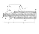
- FIG. 2 is an enlarged sectional view schematically showing capacitor element 2 included in the solid electrolytic capacitor of FIG.
- a solid electrolytic capacitor 1 includes a capacitor element 2 , an exterior body 3 that seals the capacitor element 2 , and an anode lead terminal 4 and a cathode lead terminal 5 that are at least partially exposed to the outside of the exterior body 3 . ing.
- the exterior body 3 has a substantially rectangular parallelepiped outer shape, and the solid electrolytic capacitor 1 also has a substantially rectangular parallelepiped outer shape.
- the capacitor element 2 includes an anode foil 6, a dielectric layer (not shown) covering the surface of the anode foil 6, and a cathode section 8 covering the dielectric layer.
- the dielectric layer may be formed on at least part of the surface of anode foil 6 .
- the cathode section 8 includes a solid electrolyte layer 9 and a cathode extraction layer 10 .
- the solid electrolyte layer 9 is formed by electrolytic polymerization and covers at least part of the dielectric layer.
- Cathode extraction layer 10 is formed to cover at least a portion of solid electrolyte layer 9 .
- the cathode extraction layer 10 has, for example, a first layer 11 that is a carbon layer and a second layer 12 that is a metal paste layer.
- the cathode lead terminal 5 is electrically connected to the cathode portion 8 via an adhesive layer 14 made of a conductive adhesive.
- the anode foil 6 includes a base material portion 6a and a porous portion 6b formed on the surface of the base material portion 6a. Porous portion 6 b is formed on the surface layer of anode foil 6 .
- the anode foil 6 has a first portion I where the solid electrolyte layer 9 (or the cathode portion 8) is not formed, and a second portion II other than the first portion I.
- An anode lead terminal 4 is electrically connected to the first portion I by welding.
- Anode foil 6 has a first end Ie connected to anode lead terminal 4 and a second end IIe opposite to first end Ie.
- the anode foil 6 has a first principal surface m1 and a second principal surface m2 opposite to the first principal surface m1. Between the first end portion Ie and the second end portion IIe, the first insulating portion i1p is provided on the first main surface m1 side of the anode foil 6, and the second insulating portion i1p is provided on the second main surface m2 side. A portion i2p is provided.
- the porous portion 6b contains the first insulating material, and the outer surface of the first insulating portion i1p constitutes the first insulating region i1a.
- the porous portion 6b contains at least a liquid-repellent material, and the outer surface of the second insulating portion i2p constitutes the second insulating region i2a.
- the exterior body 3 partially covers the capacitor element 2 and the lead terminals 4 and 5 . From the viewpoint of suppressing air intrusion into the exterior body 3 , it is desirable that the capacitor element 2 and part of the lead terminals 4 and 5 are sealed with the exterior body 3 .
- FIG. 1 shows the case where the exterior body 3 is a resin exterior body. The resin sheathing body is formed by sealing part of the capacitor element 2 and the lead terminals 4 and 5 with a resin material.
- One ends of the anode lead terminal 4 and the cathode lead terminal 5 are electrically connected to the capacitor element 2 , and the other ends are drawn out of the exterior body 3 .
- the solid electrolytic capacitor 1 one end sides of the lead terminals 4 and 5 are covered together with the capacitor element 2 by the exterior body 3 .
- Solid electrolytic capacitor 1 (solid electrolytic capacitor A1) shown in FIG. 1 was produced in the following manner, and its characteristics were evaluated.
- a first insulating portion i1p was formed by impregnating the entire body with a polyamide-imide resin as a first insulating material in a strip shape along the width direction and heating at 200° C. for 30 minutes.
- the outer surface of the first insulating portion i1p forms a first insulating region i1a.
- the width w1 of the first insulating region i1a was 0.07 L with respect to the length L of the anode foil 6. As shown in FIG.
- a polyamide-imide resin and a fluororesin as a liquid-repellent material are applied in a band shape along the entire width direction of the anode foil 6.
- a polyamide-imide resin and a fluororesin as a liquid-repellent material are applied in a band shape along the entire width direction of the anode foil 6.
- Megafac RS-76-E manufactured by DIC Corporation
- the outer surface of the second insulating portion i2p forms a second insulating region i2a.
- the width w2 of the second insulating region i2a was 0.07 L with respect to the length L of the anode foil 6.
- a polymerization liquid (liquid composition) containing pyrrole (monomer of conjugated polymer), naphthalenesulfonic acid (dopant), and water was prepared.
- the anode foil 6 having the precoat layer formed thereon and the counter electrode were immersed in the resulting polymerization solution.
- the superposition voltage is the potential of the current supply relative to the reference electrode (silver/silver chloride reference electrode).
- a silver paste containing silver particles and a binder resin (epoxy resin) is applied to the surface of the first layer 11 and heated at 150° C. for 30 minutes to harden the binder resin, thereby forming a second metal paste layer.
- a layer 12 was formed.
- the cathode lead layer 10 composed of the first layer 11 and the second layer 12 was formed, and the cathode portion 8 composed of the solid electrolyte layer 9 and the cathode lead layer 10 was formed.
- a capacitor element 2 was produced as described above.
- a resin sheathing body 3 made of an insulating resin was formed around the capacitor element 2 by molding. At this time, the other end portion of the anode lead terminal 4 and the other end portion of the cathode lead terminal 5 were pulled out from the resin sheathing body 3 .
- solid electrolytic capacitor 1 (A1) was completed.
- a total of 20 solid electrolytic capacitors were produced in the same manner as described above.
- Table 1 shows the evaluation results.
- the leakage current was smaller and the standard deviation was smaller than in the comparative example.
- the solid electrolyte layer 9 was also formed on the surface of the second insulating region i2a, and it is considered that the leakage current increased.
- the solid electrolytic capacitor of the present disclosure reduces leakage current and provides excellent capacitor performance. Therefore, solid electrolytic capacitors can be used, for example, in various applications that require high reliability.
Landscapes
- Engineering & Computer Science (AREA)
- Power Engineering (AREA)
- Microelectronics & Electronic Packaging (AREA)
- Chemical & Material Sciences (AREA)
- Chemical Kinetics & Catalysis (AREA)
- Electrochemistry (AREA)
- Manufacturing & Machinery (AREA)
- Polyoxymethylene Polymers And Polymers With Carbon-To-Carbon Bonds (AREA)
Priority Applications (3)
| Application Number | Priority Date | Filing Date | Title |
|---|---|---|---|
| JP2023502434A JPWO2022181607A1 (https=) | 2021-02-26 | 2022-02-22 | |
| CN202280015717.6A CN116918016A (zh) | 2021-02-26 | 2022-02-22 | 固体电解电容器及其制造方法 |
| US18/546,504 US20240128029A1 (en) | 2021-02-26 | 2022-02-22 | Solid electrolytic capacitor and manufacturing method therefor |
Applications Claiming Priority (2)
| Application Number | Priority Date | Filing Date | Title |
|---|---|---|---|
| JP2021-029880 | 2021-02-26 | ||
| JP2021029880 | 2021-02-26 |
Publications (1)
| Publication Number | Publication Date |
|---|---|
| WO2022181607A1 true WO2022181607A1 (ja) | 2022-09-01 |
Family
ID=83048141
Family Applications (1)
| Application Number | Title | Priority Date | Filing Date |
|---|---|---|---|
| PCT/JP2022/007215 Ceased WO2022181607A1 (ja) | 2021-02-26 | 2022-02-22 | 固体電解コンデンサおよびその製造方法 |
Country Status (4)
| Country | Link |
|---|---|
| US (1) | US20240128029A1 (https=) |
| JP (1) | JPWO2022181607A1 (https=) |
| CN (1) | CN116918016A (https=) |
| WO (1) | WO2022181607A1 (https=) |
Cited By (1)
| Publication number | Priority date | Publication date | Assignee | Title |
|---|---|---|---|---|
| US20240055191A1 (en) * | 2021-01-22 | 2024-02-15 | Panasonic Intellectual Property Management Co., Ltd. | Solid electrolytic capacitor element and solid electrolytic capacitor |
Citations (3)
| Publication number | Priority date | Publication date | Assignee | Title |
|---|---|---|---|---|
| JPH0645206A (ja) * | 1992-07-21 | 1994-02-18 | Elna Co Ltd | 固体電解コンデンサの製造方法 |
| JP2005079519A (ja) * | 2003-09-03 | 2005-03-24 | Matsushita Electric Ind Co Ltd | 固体電解コンデンサの製造方法 |
| JP2018032768A (ja) * | 2016-08-25 | 2018-03-01 | 株式会社村田製作所 | 固体電解コンデンサ素子、固体電解コンデンサ、固体電解コンデンサ素子の製造方法、及び、固体電解コンデンサの製造方法 |
Family Cites Families (4)
| Publication number | Priority date | Publication date | Assignee | Title |
|---|---|---|---|---|
| US9236193B2 (en) * | 2013-10-02 | 2016-01-12 | Avx Corporation | Solid electrolytic capacitor for use under high temperature and humidity conditions |
| JP6634595B2 (ja) * | 2016-02-18 | 2020-01-22 | パナソニックIpマネジメント株式会社 | 断熱材及びその製造方法 |
| CN107527740B (zh) * | 2016-06-15 | 2019-12-13 | 株式会社村田制作所 | 固体电解电容器 |
| JP7067512B2 (ja) * | 2019-03-22 | 2022-05-16 | 株式会社村田製作所 | 固体電解コンデンサ |
-
2022
- 2022-02-22 WO PCT/JP2022/007215 patent/WO2022181607A1/ja not_active Ceased
- 2022-02-22 CN CN202280015717.6A patent/CN116918016A/zh active Pending
- 2022-02-22 JP JP2023502434A patent/JPWO2022181607A1/ja not_active Withdrawn
- 2022-02-22 US US18/546,504 patent/US20240128029A1/en not_active Abandoned
Patent Citations (3)
| Publication number | Priority date | Publication date | Assignee | Title |
|---|---|---|---|---|
| JPH0645206A (ja) * | 1992-07-21 | 1994-02-18 | Elna Co Ltd | 固体電解コンデンサの製造方法 |
| JP2005079519A (ja) * | 2003-09-03 | 2005-03-24 | Matsushita Electric Ind Co Ltd | 固体電解コンデンサの製造方法 |
| JP2018032768A (ja) * | 2016-08-25 | 2018-03-01 | 株式会社村田製作所 | 固体電解コンデンサ素子、固体電解コンデンサ、固体電解コンデンサ素子の製造方法、及び、固体電解コンデンサの製造方法 |
Cited By (2)
| Publication number | Priority date | Publication date | Assignee | Title |
|---|---|---|---|---|
| US20240055191A1 (en) * | 2021-01-22 | 2024-02-15 | Panasonic Intellectual Property Management Co., Ltd. | Solid electrolytic capacitor element and solid electrolytic capacitor |
| US12354812B2 (en) * | 2021-01-22 | 2025-07-08 | Panasonic Intellectual Property Management Co., Ltd. | Solid electrolytic capacitor element and solid electrolytic capacitor |
Also Published As
| Publication number | Publication date |
|---|---|
| CN116918016A (zh) | 2023-10-20 |
| US20240128029A1 (en) | 2024-04-18 |
| JPWO2022181607A1 (https=) | 2022-09-01 |
Similar Documents
| Publication | Publication Date | Title |
|---|---|---|
| JP7607231B2 (ja) | 電解コンデンサおよびその製造方法 | |
| JPWO2018020985A1 (ja) | 電解コンデンサおよびその製造方法 | |
| JP7734327B2 (ja) | 固体電解コンデンサ素子および固体電解コンデンサ | |
| JP7752360B2 (ja) | 固体電解コンデンサ素子および固体電解コンデンサ | |
| CN107533920B (zh) | 电解电容器及其制造方法 | |
| JP7108811B2 (ja) | 電解コンデンサおよびその製造方法 | |
| WO2018123525A1 (ja) | 電解コンデンサ | |
| WO2022181607A1 (ja) | 固体電解コンデンサおよびその製造方法 | |
| US12394571B2 (en) | Solid-electrolyte capacitor and method for manufacturing same | |
| CN115398575A (zh) | 固体电解电容器及其制造方法 | |
| JP7620821B2 (ja) | 電解コンデンサおよびコンデンサ素子 | |
| WO2023074172A1 (ja) | 固体電解コンデンサ素子および固体電解コンデンサ | |
| US12198869B2 (en) | Electrolytic capacitor and manufacturing method thereof | |
| CN118974863A (zh) | 固体电解电容器元件及固体电解电容器、以及固体电解电容器元件的制造方法 | |
| JP7727953B2 (ja) | 固体電解コンデンサ素子および固体電解コンデンサ、固体電解コンデンサ素子の製造方法 | |
| WO2021172123A1 (ja) | 電解コンデンサおよび電解コンデンサの導電層形成用ペースト | |
| JP7706082B2 (ja) | 固体電解コンデンサ | |
| JP7664526B2 (ja) | 固体電解コンデンサおよびその製造方法 | |
| CN115485800B (zh) | 固体电解电容器元件和固体电解电容器 | |
| JP3551118B2 (ja) | コンデンサ及びその製造方法 | |
| US20250104928A1 (en) | Electrolytic capacitor and method of manufacturing same | |
| JP2013258273A (ja) | コンデンサ用マスキング樹脂組成物、コンデンサ素子、コンデンサおよびコンデンサの製造方法 | |
| JP2022156883A (ja) | 固体電解コンデンサ用導電性ペースト、固体電解コンデンサおよびその製造方法 | |
| WO2023119843A1 (ja) | 固体電解コンデンサ素子および固体電解コンデンサ | |
| WO2024203133A1 (ja) | 固体電解コンデンサ素子およびその製造方法、ならびに固体電解コンデンサ |
Legal Events
| Date | Code | Title | Description |
|---|---|---|---|
| 121 | Ep: the epo has been informed by wipo that ep was designated in this application |
Ref document number: 22759643 Country of ref document: EP Kind code of ref document: A1 |
|
| ENP | Entry into the national phase |
Ref document number: 2023502434 Country of ref document: JP Kind code of ref document: A |
|
| WWE | Wipo information: entry into national phase |
Ref document number: 18546504 Country of ref document: US |
|
| WWE | Wipo information: entry into national phase |
Ref document number: 202280015717.6 Country of ref document: CN |
|
| NENP | Non-entry into the national phase |
Ref country code: DE |
|
| 122 | Ep: pct application non-entry in european phase |
Ref document number: 22759643 Country of ref document: EP Kind code of ref document: A1 |