WO2022181523A1 - 自動車の室内温度調節装置及び電気自動車 - Google Patents
自動車の室内温度調節装置及び電気自動車 Download PDFInfo
- Publication number
- WO2022181523A1 WO2022181523A1 PCT/JP2022/006872 JP2022006872W WO2022181523A1 WO 2022181523 A1 WO2022181523 A1 WO 2022181523A1 JP 2022006872 W JP2022006872 W JP 2022006872W WO 2022181523 A1 WO2022181523 A1 WO 2022181523A1
- Authority
- WO
- WIPO (PCT)
- Prior art keywords
- air
- air conditioner
- seat
- temperature
- vehicle
- Prior art date
- Legal status (The legal status is an assumption and is not a legal conclusion. Google has not performed a legal analysis and makes no representation as to the accuracy of the status listed.)
- Ceased
Links
Images










Classifications
-
- B—PERFORMING OPERATIONS; TRANSPORTING
- B60—VEHICLES IN GENERAL
- B60N—SEATS SPECIALLY ADAPTED FOR VEHICLES; VEHICLE PASSENGER ACCOMMODATION NOT OTHERWISE PROVIDED FOR
- B60N2/00—Seats specially adapted for vehicles; Arrangement or mounting of seats in vehicles
- B60N2/56—Heating or ventilating devices
- B60N2/5607—Heating or ventilating devices characterised by convection
- B60N2/5621—Heating or ventilating devices characterised by convection by air
- B60N2/5642—Heating or ventilating devices characterised by convection by air with circulation of air through a layer inside the seat
-
- B—PERFORMING OPERATIONS; TRANSPORTING
- B60—VEHICLES IN GENERAL
- B60N—SEATS SPECIALLY ADAPTED FOR VEHICLES; VEHICLE PASSENGER ACCOMMODATION NOT OTHERWISE PROVIDED FOR
- B60N2/00—Seats specially adapted for vehicles; Arrangement or mounting of seats in vehicles
- B60N2/56—Heating or ventilating devices
- B60N2/5607—Heating or ventilating devices characterised by convection
- B60N2/5621—Heating or ventilating devices characterised by convection by air
- B60N2/5628—Heating or ventilating devices characterised by convection by air coming from the vehicle ventilation system, e.g. air-conditioning system
-
- A—HUMAN NECESSITIES
- A47—FURNITURE; DOMESTIC ARTICLES OR APPLIANCES; COFFEE MILLS; SPICE MILLS; SUCTION CLEANERS IN GENERAL
- A47C—CHAIRS; SOFAS; BEDS
- A47C7/00—Parts, details, or accessories of chairs or stools
- A47C7/36—Supports for the head or the back
- A47C7/38—Supports for the head or the back for the head, e.g. detachable
-
- A—HUMAN NECESSITIES
- A47—FURNITURE; DOMESTIC ARTICLES OR APPLIANCES; COFFEE MILLS; SPICE MILLS; SUCTION CLEANERS IN GENERAL
- A47C—CHAIRS; SOFAS; BEDS
- A47C7/00—Parts, details, or accessories of chairs or stools
- A47C7/62—Accessories for chairs
- A47C7/72—Adaptations for incorporating lamps, radio sets, bars, telephones, ventilation, heating or cooling arrangements or the like
- A47C7/74—Adaptations for incorporating lamps, radio sets, bars, telephones, ventilation, heating or cooling arrangements or the like for ventilation, heating or cooling
-
- B—PERFORMING OPERATIONS; TRANSPORTING
- B60—VEHICLES IN GENERAL
- B60H—ARRANGEMENTS OF HEATING, COOLING, VENTILATING OR OTHER AIR-TREATING DEVICES SPECIALLY ADAPTED FOR PASSENGER OR GOODS SPACES OF VEHICLES
- B60H1/00—Heating, cooling or ventilating devices
- B60H1/00421—Driving arrangements for parts of a vehicle air-conditioning
- B60H1/00428—Driving arrangements for parts of a vehicle air-conditioning electric
-
- B—PERFORMING OPERATIONS; TRANSPORTING
- B60—VEHICLES IN GENERAL
- B60H—ARRANGEMENTS OF HEATING, COOLING, VENTILATING OR OTHER AIR-TREATING DEVICES SPECIALLY ADAPTED FOR PASSENGER OR GOODS SPACES OF VEHICLES
- B60H1/00—Heating, cooling or ventilating devices
- B60H1/00642—Control systems or circuits; Control members or indication devices for heating, cooling or ventilating devices
- B60H1/00735—Control systems or circuits characterised by their input, i.e. by the detection, measurement or calculation of particular conditions, e.g. signal treatment, dynamic models
- B60H1/00764—Control systems or circuits characterised by their input, i.e. by the detection, measurement or calculation of particular conditions, e.g. signal treatment, dynamic models the input being a vehicle driving condition, e.g. speed
-
- B—PERFORMING OPERATIONS; TRANSPORTING
- B60—VEHICLES IN GENERAL
- B60H—ARRANGEMENTS OF HEATING, COOLING, VENTILATING OR OTHER AIR-TREATING DEVICES SPECIALLY ADAPTED FOR PASSENGER OR GOODS SPACES OF VEHICLES
- B60H1/00—Heating, cooling or ventilating devices
- B60H1/00642—Control systems or circuits; Control members or indication devices for heating, cooling or ventilating devices
- B60H1/00735—Control systems or circuits characterised by their input, i.e. by the detection, measurement or calculation of particular conditions, e.g. signal treatment, dynamic models
- B60H1/00807—Control systems or circuits characterised by their input, i.e. by the detection, measurement or calculation of particular conditions, e.g. signal treatment, dynamic models the input being a specific way of measuring or calculating an air or coolant temperature
-
- B—PERFORMING OPERATIONS; TRANSPORTING
- B60—VEHICLES IN GENERAL
- B60N—SEATS SPECIALLY ADAPTED FOR VEHICLES; VEHICLE PASSENGER ACCOMMODATION NOT OTHERWISE PROVIDED FOR
- B60N2/00—Seats specially adapted for vehicles; Arrangement or mounting of seats in vehicles
- B60N2/56—Heating or ventilating devices
- B60N2/5607—Heating or ventilating devices characterised by convection
- B60N2/5621—Heating or ventilating devices characterised by convection by air
- B60N2/5657—Heating or ventilating devices characterised by convection by air blown towards the seat surface
-
- B—PERFORMING OPERATIONS; TRANSPORTING
- B60—VEHICLES IN GENERAL
- B60N—SEATS SPECIALLY ADAPTED FOR VEHICLES; VEHICLE PASSENGER ACCOMMODATION NOT OTHERWISE PROVIDED FOR
- B60N2/00—Seats specially adapted for vehicles; Arrangement or mounting of seats in vehicles
- B60N2/80—Head-rests
- B60N2/879—Head-rests with additional features not related to head-rest positioning, e.g. heating or cooling devices or loudspeakers
-
- B—PERFORMING OPERATIONS; TRANSPORTING
- B60—VEHICLES IN GENERAL
- B60N—SEATS SPECIALLY ADAPTED FOR VEHICLES; VEHICLE PASSENGER ACCOMMODATION NOT OTHERWISE PROVIDED FOR
- B60N2210/00—Sensor types, e.g. for passenger detection systems or for controlling seats
- B60N2210/30—Temperature sensors
Definitions
- the present invention relates to an automobile interior temperature control device and an electric vehicle, and more particularly to an automobile interior temperature control device having an air conditioner and a seat temperature control device and an electric vehicle equipped with the temperature control device.
- An electric air conditioner in which the compressor of an air conditioner using a refrigeration cycle is driven by an electric motor has the problem that the power consumption of the electric motor is greater than the power consumption of the seat heater, and the power consumption of the battery is large.
- the problem to be solved by the present invention is to achieve both a comfortable temperature environment for the occupants and a reduction in power consumption in an automobile interior temperature control device.
- An automotive interior temperature control device is an interior temperature control device for controlling the temperature in a vehicle interior, and comprises an air outlet ( 52), and at least one of an air blowing device or a seat heater blowing air whose temperature is adjusted by at least one of a heater and a semiconductor device toward an occupant seated in the seat.
- a seat temperature control device (60, 62, 76) that consumes less power than the air conditioner, and a control device that operates the seat temperature control device for a predetermined period when the air conditioner is started ( 100).
- the air conditioner includes a refrigeration cycle including a compressor (42) driven by an electric motor (54).
- the predetermined period is a period from when the air conditioner is started until a predetermined time elapses.
- the seat temperature control device operates until a predetermined time elapses from the start of the air conditioner, and it is possible to quickly obtain a comfortable temperature environment and reduce power consumption.
- the predetermined period is a period from when the air conditioner is started, during which the difference between the set temperature of the air conditioner and the vehicle interior temperature is equal to or greater than a predetermined value.
- the seat temperature control device operates during a period in which the difference between the set temperature of the air conditioner and the vehicle interior temperature is equal to or greater than the predetermined value after the start of the air conditioner, and a comfortable environment regarding temperature is quickly obtained. and reduction of power consumption are compatible.
- the control device lowers the adjustment temperature of the seat temperature control device in the first half of the operation period compared to the latter half.
- the control device reduces the amount of air blown by the air blowing device in the first half of the operation period compared to the second half.
- the control device intermittently operates the air blowing device.
- the average power consumption of the air blowing device is reduced compared to continuous operation, and the power consumption of the air blowing device is reduced.
- the control device operates the air conditioner with a power value lower than the power value for steady operation while the seat temperature control device is in operation.
- the air blowing device is provided in the seat back or headrest of the seat and includes an air blowing port for blowing the air toward the neck of the seated person.
- An electric vehicle is an electric vehicle in which traveling wheels are driven by an electric motor, and includes the indoor temperature control device according to the above embodiment, wherein the electric motor driving the traveling wheels, the compression A battery is a common power source for the electric motor that drives the machine and the seat temperature control device.
- the power consumption of the battery is reduced, and the decrease in the cruising range of the electric vehicle is suppressed.
- An air-conditioning seat having a blowout path for blowing air from the seat surface is known (for example, Japanese Patent Laid-Open No. 2019-84295).
- the air-conditioned seat described in the publication includes a seat back that serves as a backrest for a seated person, and a seat cushion that serves as a sitting portion.
- An air conditioner with a blower function is provided under the seat cushion.
- Both sides of the seat cushion are provided with panel members projecting in the shape of upright plates. The upper edge of the panel material is bent inward in the seat width direction.
- Each of the panel materials has a shape in which the wind sent out from the air conditioner blows along the inner surface in the seat width direction toward the seat upper side (seat surface side), and the upper edge side is bent inward in the seat width direction. guides the air to blow out from the side toward the thighs of the seated person.
- the vehicle seat is equipped with a buckle that can be engaged and disengaged from the tongue of the seat belt. If the buckle is displaceably provided on the side portion of the seat cushion, there is a possibility that the displacement may be hindered by the panel material.
- the present invention provides a vehicle seat that includes an air conditioner provided on a seat cushion and a buckle that can be engaged with and disengaged from a tongue of a seat belt so that movement of the buckle is less likely to be hindered by the air conditioner. and a vehicle provided with the vehicle seat.
- one aspect of the present invention is a vehicle seat (103, 303, 403, 503) comprising a seat body (105) having a seat cushion (111) and a seat back (113). , a buckle (151B) that is rotatably supported by the seat body about the axis (Q) in the left-right direction and can be engaged with and disengaged from the tongue of the seat belt, and an air conditioner (163) for adjusting the ambient temperature of the seated person. , 171, 173, 175, 371A, 663), and the air conditioner is coupled to the seat cushion outside the movable range of the buckle.
- the air conditioner is connected to the seat cushion outside the movable range of the buckle, it is possible to prevent the movement of the buckle from being hindered by the air conditioner.
- the air conditioner is arranged at a position overlapping the range of motion in a front view.
- the width of the vehicle seat in the left-right direction can be made smaller than when the air conditioner does not overlap the range of motion in front view.
- the air conditioner is arranged at a position overlapping the movable range in a side view.
- the air conditioner is less likely to protrude forward from the seat body. can.
- the air conditioner is arranged outside the movement area (E) of the tongue engaged with the buckle.
- the seat cushion preferably has a frame (121), a pad member (123) supported by the frame, and a skin material (125) covering the surface of the pad member,
- the pad member is provided with a notch (183) cut to receive the air conditioner.
- the right and left side portions of the seat body are provided with an operation input portion (149) for changing any one of shape, posture, and position, and the air conditioning device is configured to operate as described above. It is arranged forward of the rear end of the operation input unit.
- the operation input of the seated person is less likely to be obstructed by the air conditioner.
- the air conditioner is arranged forward of the front end of the operation input section.
- the operation input of the seated person is less likely to be obstructed by the air conditioner.
- operation input units (449) for changing any one of shape, posture, and position are provided on the left and right side portions of the seat body, and the air conditioning device operates as described above. It is arranged between the front end and the rear end of the operation input section.
- an operation input section for changing any one of the shape, posture, and position of the seat body is provided, and the outer ends of the air conditioner in the left-right direction are located on the left and right sides of the operation input section. It is positioned inward of the seat from the direction outer end.
- the operation input of the seated person is less likely to be obstructed by the air conditioner.
- the seat back is provided with a side airbag (137) that deploys to the side of the occupant, and the air conditioner is positioned outside the deployment area (C) of the side airbag. ing.
- the air conditioner is positioned in front of the deployment area.
- the seat back is provided with a side airbag (137) that deploys to the side of the seated person, and the front end of the deployment area of the side airbag is the lower end of the deployment area (C).
- the upper edge of the air conditioner is substantially horizontal, and the rear end of the air conditioner is positioned below the front end of the deployment area.
- deployment of the side airbag is less likely to be hindered by the air conditioner.
- the seat body has a headrest, a cylindrical pillar guide (131D) is provided at the upper end of the seatback, and the headrest is a pillar (115A) inserted into the pillar guide. ), and a temperature control device (207) having a heat source (207A) is provided at the upper end of the seat back, and the heat source is located behind the pillar guide.
- the heat source is arranged behind the pillar guide. Therefore, when a rearward load is applied to the seated person, the pillar guide and the pillars hinder the rearward movement of the neck of the seated person, thereby preventing the neck of the seated person from approaching the heat source.
- one aspect of the present invention is a vehicle (100) equipped with the vehicle seat described above, in which a door (107) is provided with a door airbag ( 108) is provided, and the air conditioner is located outside the deployment area (A) of the door airbag.
- deployment of the door airbag is less likely to be hindered by the air conditioner.
- a center console box (109) is provided on the side of the vehicle seat, and the center console box has a storage recess (109A) that opens to store articles, and a storage recess (109A). It has a lid (1019B) that is hinged to the opening edge (109C) and opens and closes the accommodation recess, and the air conditioner is positioned outside the movable range (B) of the lid.
- opening and closing of the lid is less likely to be hindered by the air conditioner.
- one aspect of the present invention is a vehicle seat, comprising: a seat body including a seat cushion and a seat back; a buckle supported and releasable from a tongue of a seat belt; and an air conditioner for regulating the ambient temperature of the occupant, the air conditioner being coupled to the seat cushion outside the range of motion of the buckle.
- the air conditioner since the air conditioner is coupled to the seat cushion outside the movable range of the buckle, it is possible to prevent the movement of the buckle from being hindered by the air conditioner.
- the air conditioner is arranged at a position overlapping the range of motion in a front view.
- the width of the vehicle seat in the left-right direction can be made smaller than when the air conditioner does not overlap the range of motion in front view.
- the air conditioner is arranged at a position overlapping the movable range in a side view. According to this aspect, compared to the case where the air conditioner does not overlap the range of motion in a side view, the air conditioner is less likely to protrude forward from the seat body. can.
- the air conditioner is arranged outside the movement area of the tongue engaged with the buckle. According to this aspect, it is possible to prevent the movement of the tongue from being hindered by the air conditioner.
- the seat cushion includes a frame, a pad member supported by the frame, and a skin material covering a surface of the pad member, and the pad member includes the air conditioner. Receiving cutouts are provided. According to this aspect, the size of the vehicle seat can be reduced by providing the air conditioner in the notch provided in the pad member.
- the right and left side portions of the seat body are provided with operation input units for changing any one of shape, posture, and position, and the air conditioner is provided with the operation input units. positioned forward of the rear end of the According to this aspect, the operation input of the seated person is less likely to be obstructed by the air conditioner.
- the air conditioner is arranged forward of the front end of the operation input unit. According to this aspect, the operation input of the seated person is less likely to be obstructed by the air conditioner.
- the right and left side portions of the seat body are provided with operation input units for changing any one of shape, posture, and position, and the air conditioner is provided with the operation input units. located between the front and rear ends of the According to this aspect, it is possible to reduce the size of the vehicle seat in the front-rear direction.
- an operation input section for changing any one of the shape, posture, and position of the seat body is provided, and the outer ends of the air conditioner in the left-right direction are located on the left and right sides of the operation input section. It is positioned inward of the seat from the direction outer end. According to this aspect, the operation input of the seated person is less likely to be obstructed by the air conditioner.
- the seatback is provided with a side airbag that deploys to the side of the seated person, and the air conditioner is positioned outside the deployment area of the side airbag. According to this aspect, it is possible to prevent the deployment of the side airbag from being hindered by the air conditioner.
- the air conditioner is positioned in front of the deployment area. According to this aspect, it is possible to prevent the deployment of the side airbag from being hindered by the air conditioner.
- the seat back is provided with a side airbag that deploys to the side of the seated person, the front end of the deployment area of the side airbag is positioned at the lower end of the deployment area, and the air-conditioning The upper edge of the device is arranged substantially horizontally and the rear end of the air conditioner is located below the front end of the deployment zone. According to this aspect, deployment of the side airbag is less likely to be hindered by the air conditioner.
- the seat body has a headrest
- a tubular pillar guide is provided at the upper end of the seatback
- the headrest has a pillar inserted into the pillar guide
- the A temperature control device having a heat source is provided at the upper end of the seatback, and the heat source is positioned behind the pillar guide.
- the heat source is arranged behind the pillar guide. Therefore, when a rearward load is applied to the seated person, the pillar guide and the pillars hinder the rearward movement of the neck of the seated person, thereby preventing the neck of the seated person from approaching the heat source.
- one aspect of the present invention is a vehicle including the above-described vehicle seat, wherein a door is provided with a door airbag that deploys into the vehicle interior, and the air conditioner includes the door airbag. Located outside the deployment area of the bag. According to this aspect, deployment of the door airbag is less likely to be hindered by the air conditioner.
- a center console box is provided on the side of the vehicle seat, and the center console box is hingedly connected to a storage recess that opens to store articles and an opening edge of the storage recess. , and a lid for opening and closing the accommodation recess, and the air conditioner is positioned outside the movable range of the lid. According to this aspect, opening and closing of the lid is less likely to be hindered by the air conditioner.
- Patent Literature 1 There is a known seat mounted on a vehicle that has a blowout path for blowing air from the surface of the seat (for example, Japanese Patent Application Laid-Open No. 2019-84295).
- the seat described in Patent Literature 1 includes a seat back that serves as a backrest portion for a seated person, and a seat cushion that serves as a sitting portion.
- An air conditioner with a blower function is provided under the seat cushion.
- Both sides of the seat cushion are provided with panel members projecting in the shape of upright plates. The upper edge of the panel material is bent inward in the seat width direction.
- Each of the panel materials has a shape in which the wind sent out from the air conditioner blows along the inner surface in the seat width direction toward the seat upper side (seat surface side), and the upper edge side is bent inward in the seat width direction. guide the air to blow out from the left and right toward the thighs of the seated person.
- the vehicle will have doors and windows. Areas near doors and windows are susceptible to outside air.
- a temperature difference may occur between the left and right winds blowing toward the seated occupant.
- an object of the present invention is to provide an air conditioning system that is less susceptible to the outside temperature.
- one aspect of the present invention is an air conditioning system (161), which is provided in a vehicle seat (103) and includes a seat air conditioner (163) for air conditioning around a seated person,
- the seat air conditioner includes a vehicle-exterior air conditioner (171B) that performs air conditioning from the vehicle exterior and a vehicle interior air conditioner (171A) that performs air conditioning from the vehicle interior. Greater than the output of the inner air conditioner.
- the output of the vehicle-exterior air conditioner that air-conditions the vehicle exterior, which is easily affected by the outside air is set higher than the output of the vehicle interior air conditioner, so that the influence of the outside air temperature can be reduced.
- each of the vehicle-exterior air conditioner and the vehicle-interior air conditioner has a blower (193) that blows air toward the seated occupant, and a heat source (197A) that adjusts the temperature of the air blown by the blower. ), and the outputs of the vehicle-exterior air conditioner and the vehicle-interior air conditioner respectively correspond to the amount of temperature change in the air caused by the heat source.
- the influence of outside air can be reduced by making the amount of temperature change on the outside of the vehicle, which is susceptible to the influence of outside air, larger than that on the inside of the vehicle.
- the vehicle-exterior air conditioner and the vehicle-interior air conditioner are each provided with a seat cushion (111) of the vehicle seat to control the temperature around the legs of the seated person.
- the vehicle interior air conditioner and the vehicle exterior air conditioner each include a duct (195) extending from the blower and extending forward from the front end of the seat cushion.
- the air sent out from the blower can be guided to the feet of the seated person.
- the seat cushion has a base portion (111B) forming a central portion in the left-right direction, and bank portions (111C) connected to both left and right edges of the base portion and protruding upward from the upper surface of the base portion. and the front ends of the ducts are open below the upper surface of the embankment.
- the ducts are less likely to come into contact with the thighs.
- the seat cushion has a pair of left and right side frames (121A) extending in the front-rear direction, and side covers (127) are provided outside the seat of the side frames, respectively,
- the ducts are located inside the seat from the left and right end portions of the side covers.
- the seat air conditioner is provided in the seat back of the vehicle seat and includes a back-side air conditioner (173) that controls temperature by blowing air toward the neck of the seated person.
- the output of the vehicle-exterior air conditioner is greater than the output of the back-side air conditioner.
- the back-side air conditioner includes a blower (203) for sending air to the neck of the seated person, and a heat source (207A) for changing the temperature of the air to be sent to the neck
- the output of the vehicle-exterior air conditioner corresponds to the amount of air temperature change caused by the heat source (197A) of the vehicle-exterior air conditioner
- the output of the back-side air conditioner is the air temperature caused by the heat source (207A) of the back-side air conditioner. It corresponds to the amount of change.
- the temperature change of the air blown to the outside of the vehicle of the leg is larger than that of the air blown to the neck, the influence of the outside air can be effectively suppressed on the outside of the vehicle of the leg, which is likely to be affected by the outside air. can be done.
- the seat air conditioner is provided in the headrest (115) of the vehicle seat and blows air toward the head of the seated person to adjust the temperature. 175), wherein the output of the vehicle-exterior air conditioner is greater than the output of the head-side air conditioner.
- the head-side air conditioner includes a blower (213) for sending air to the head of the seated person, and a heat source (117A) for changing the temperature of the air sent to the head.
- the output of the vehicle-exterior air conditioner corresponds to the amount of air temperature change caused by the heat source (197A) of the vehicle-exterior air conditioner
- the output of the head-side air conditioner is caused by the heat source (217A) of the head-side air conditioner. It corresponds to the amount of temperature change in the air.
- a temperature sensor (167) that acquires the temperature of the vehicle interior in which the vehicle seat is placed, and control of the seat air conditioner based on the temperature acquired by the temperature sensor.
- a control device (181) configured to drive the seat air conditioner to cool the seated occupant when the temperature obtained by the temperature sensor is equal to or higher than an upper threshold, and When the acquired temperature is below the lower threshold, it is driven to warm the seated occupant.
- air conditioning can be performed based on the temperature in the vehicle interior where the person sitting on the vehicle seat is located.
- a temperature sensor (167) that acquires the surface temperature of the vehicle seat
- a control device (181) that controls the seat air conditioner based on the temperature acquired by the temperature sensor. ), wherein the control device drives the seat air conditioner to cool the seated occupant when the temperature acquired by the temperature sensor is equal to or higher than an upper threshold, and the temperature acquired by the temperature sensor is lowered. When it is equal to or less than the side threshold, it is driven to warm the seated person.
- air conditioning can be performed based on the temperature of the vehicle seat that the seated person touches.
- the seat air conditioner is provided in the seat back (113) of the vehicle seat, and performs temperature control by blowing air toward the neck of the seated person (back side air conditioner ( 173), a temperature sensor (167) for acquiring the surface temperature of the vehicle seat or the temperature in the vehicle interior, and a control device (181) for controlling the seat air conditioner based on the temperature acquired by the temperature sensor. ), wherein when the temperature obtained by the temperature sensor is equal to or higher than an upper threshold value, the control device increases the output of the back-side air conditioner to be higher than that of the vehicle-exterior air conditioner, and obtains the output by the temperature sensor. When the obtained temperature is equal to or lower than the lower threshold, the output of the vehicle-exterior air conditioner is made larger than that of the back-side air conditioner.
- the output of the back-side air conditioner that air-conditions the area around the neck increases.
- the output of the vehicle-exterior air conditioner that air-conditions the area around the legs increases. Therefore, when the seated person feels hot, the neck is cooled more than the leg, and when the seated person feels cold, the leg is warmed more than the neck, thereby improving the comfort of the vehicle seat.
- the vehicle further includes a vehicle interior air conditioner (664) that operates to air-condition a vehicle interior in which the vehicle seat is placed, wherein the vehicle interior air conditioner is the seat air conditioner. is driven, the operation is started when the temperature obtained by the temperature sensor reaches or exceeds a predetermined value.
- a vehicle interior air conditioner (664) that operates to air-condition a vehicle interior in which the vehicle seat is placed, wherein the vehicle interior air conditioner is the seat air conditioner. is driven, the operation is started when the temperature obtained by the temperature sensor reaches or exceeds a predetermined value.
- the passenger compartment air conditioner when the seated person is seated, the passenger compartment air conditioner operates after the seat air conditioner operates. In this way, since the air conditioners are operated in order from the side closest to the seated person, the temperature around the seated person can be adjusted more quickly than when the seat air conditioner is operated after the passenger compartment air conditioner is operated. can.
- the vehicle interior air conditioner (664) further includes a vehicle interior air conditioner (664) that operates to air-condition a vehicle interior in which the vehicle seat is placed, After the device is driven, the operation is started when the temperature obtained by the temperature sensor is maintained at a predetermined value or higher for a predetermined period of time.
- the seat air conditioner when the occupant is seated, the seat air conditioner operates, and after the temperature sensor maintains the surface temperature of the vehicle seat equal to or higher than the threshold value, the passenger compartment air conditioner operates. As a result, malfunction of the passenger compartment air conditioner due to erroneous detection by the temperature sensor can be prevented.
- a vehicle seat headrest that includes a cylindrical headrest pillar and a harness extending inside the headrest pillar (for example, Japanese Patent Application Laid-Open No. 2020-131786).
- a communication hole is formed in the headrest pillar to communicate the inside and the outside of the headrest pillar.
- the harness is connected to the electrical equipment arranged inside the headrest via the communication hole. Further, the communication hole is provided with a closing member for closing the communication hole.
- Pads are integrated with the headrest pillar, the harness, and the electrical equipment, and the pads are covered with skin.
- the headrest described in Japanese Patent Application Laid-Open No. 2020-131786 includes an outer skin, an upper portion of a headrest pillar including a communication hole, and a harness connected to an electrical component through the communication hole in a mold for molding the pad. and foaming the foaming agent.
- the foaming agent interferes with the harness when forming the pad.
- the harness is deformed integrally with the pad, resulting in a problem that the harness is easily deteriorated.
- the present invention provides a headrest for a vehicle seat in which the pad can be foam-molded without interfering with the harness extending inside the headrest pillar.
- one aspect of the present invention is a headrest (1) for a vehicle seat (2), which extends upwardly from the upper portion of the seat back (4) and has a pillar hole (16) therein.
- left and right headrest pillars (10) having a cylindrical shape defining a; a plate (12) connected to the left and right headrest pillars and facing forward and backward; a temperature control unit (14) arranged below the plate; a protective cover (71) disposed behind the plate and cooperating with the plate and the temperature control unit to define a hollow portion (70);
- the temperature control unit includes an air passage (67) extending from an air inlet (64) to an air outlet (65), and the hollow a casing (28) fixed to the plate and having a harness hole (47) communicating between the air passage and the air passage; a blower (30) that is fixed in the casing and blows the temperature-controlled air out of the casing through the air outlet, the temperature adjustment unit and the blower a harness (32) for supplying power to the headrest pillar, wherein the
- the harness connected to the temperature control unit and the blower can extend through the harness hole, the hollow portion, and the pillar hole, and protrude from the lower end of the headrest pillar. .
- These spaces are separated from the pad by the plate, protective cover and casing so that the pad can be foam molded in the headrest of the vehicle seat without interfering with the harness running through the headrest pillar.
- the protective cover includes a plate-shaped cover central portion (72) extending downward toward the rear, and left and right cover side portions extending forward and downward from left and right side edges of the cover central portion. (73) and abut against the plate at the front edge of the central portion of the cover and the front edges of the left and right side portions of the cover.
- the plate and the protective cover can be closely connected.
- a connecting piece (24) extending rearward is provided on the lower part of the plate, and the casing is connected to the connecting piece.
- left and right slanted pieces (23) slanted downward toward left and right outward are provided on the side edges of the connecting pieces, and the left and right headrest pillars are connected to the corresponding slanting pieces. I hope it is.
- the front end of the temperature control unit may be arranged behind the front end of the plate.
- the intake port is provided on one of the left and right side portions of the casing.
- the intake port can be arranged on the side window side of the vehicle, so air can be easily introduced through the intake port.
- louver plates (111) extending downward from left to right are formed in the air inlet.
- blower port is provided in the front portion of the casing, and the louver plate extends forward to the left and right.
- the air temperature-controlled by the temperature control unit is easily introduced into the casing through the intake port.
- the temperature adjustment unit can efficiently adjust the temperature.
- the rear end of the intake port is arranged forward of the headrest pillar in a side view.
- the air temperature-controlled by the temperature control unit is easily introduced into the casing through the intake port.
- the temperature adjustment unit can efficiently adjust the temperature of the air around the intake port.
- the harness connected to the temperature control unit and the blower can extend through the harness hole, the hollow portion, and the pillar hole, and protrude from the lower end of the headrest pillar.
- These spaces are separated from the padding by plates, protective covers and casings so that a headrest can be manufactured in which the padding can be foam molded without interfering with the harness running inside the headrest pillar.
- the headrest pillar and the plate are made of metal, and the left and right headrest pillars and the plate are welded in the first step.
- the headrest pillar and the plate can be fixed with simple means.
- the casing upper portion has an engaging portion (45)
- the plate has an engaged portion (25) that engages with the engaging portion
- the second step it is preferable that the engaging portion and the engaged portion are engaged with each other.
- the plate and upper casing can be fixed with a simple means.
- the headrest pillar, the plate, and the upper part of the casing are placed in a mold, and a molding material is supplied into the mold to perform foam molding. Good.
- the pad can be fixed to the headrest pillar, the plate, and the upper part of the casing with simple means.
- the casing upper portion and the casing lower portion are preferably fastened together.
- the casing upper part and the casing lower part can be fixed with a simple means.
- An automotive interior temperature control device is an interior temperature control device for controlling the temperature in a vehicle interior, and comprises an air outlet ( 52), and at least one of an air blowing device or a seat heater blowing air whose temperature is adjusted by at least one of a heater and a semiconductor device toward an occupant seated in the seat.
- a seat temperature control device (60, 62, 76) that consumes less power than the air conditioner, and a control device that operates the seat temperature control device for a predetermined period when the air conditioner is started ( 100).
- the air conditioner includes a refrigeration cycle including a compressor (42) driven by an electric motor (54).
- the predetermined period is a period from when the air conditioner is started until a predetermined time elapses.
- the seat temperature control device operates until a predetermined time elapses from the start of the air conditioner, and it is possible to quickly obtain a comfortable temperature environment and reduce power consumption.
- the predetermined period is a period from when the air conditioner is started, during which the difference between the set temperature of the air conditioner and the vehicle interior temperature is equal to or greater than a predetermined value.
- the seat temperature control device operates during a period in which the difference between the set temperature of the air conditioner and the vehicle interior temperature is equal to or greater than the predetermined value after the start of the air conditioner, and a comfortable environment regarding temperature is quickly obtained. and reduction of power consumption are compatible.
- the control device lowers the adjustment temperature of the seat temperature control device in the first half of the operation period compared to the latter half.
- the control device reduces the amount of air blown by the air blowing device in the first half of the operation period compared to the second half.
- the control device intermittently operates the air blowing device.
- the average power consumption of the air blowing device is reduced compared to continuous operation, and the power consumption of the air blowing device is reduced.
- the control device operates the air conditioner with a power value lower than the power value for steady operation while the seat temperature control device is in operation.
- the air blowing device is provided in the seat back or headrest of the seat and includes an air blowing port for blowing the air toward the neck of the seated person.
- An electric vehicle is an electric vehicle in which traveling wheels are driven by an electric motor, and includes the indoor temperature control device according to the above embodiment, wherein the electric motor driving the traveling wheels, the compression A battery is a common power source for the electric motor that drives the machine and the seat temperature control device.
- the power consumption of the battery is reduced, and the decrease in the cruising range of the electric vehicle is suppressed.
- one aspect of the present invention is a vehicle seat, comprising: a seat body including a seat cushion and a seat back; It has a buckle that can be engaged with and disengaged from the tongue of a seat belt, and an air conditioner for adjusting the ambient temperature of a seated person, and the air conditioner is coupled to the seat cushion outside the movable range of the buckle.
- the air conditioner since the air conditioner is coupled to the seat cushion outside the movable range of the buckle, it is possible to prevent the movement of the buckle from being hindered by the air conditioner.
- the air conditioner is arranged at a position overlapping the range of motion in a front view.
- the width of the vehicle seat in the left-right direction can be made smaller than when the air conditioner does not overlap the range of motion in front view.
- the air conditioner is arranged at a position overlapping the movable range in a side view. According to this aspect, compared to the case where the air conditioner does not overlap the range of motion in a side view, the air conditioner is less likely to protrude forward from the seat body. can.
- the air conditioner is arranged outside the movement area of the tongue engaged with the buckle. According to this aspect, it is possible to prevent the movement of the tongue from being hindered by the air conditioner.
- the seat cushion includes a frame, a pad member supported by the frame, and a skin material covering a surface of the pad member, and the pad member includes the air conditioner. Receiving cutouts are provided. According to this aspect, the size of the vehicle seat can be reduced by providing the air conditioner in the notch provided in the pad member.
- the right and left side portions of the seat body are provided with operation input units for changing any one of shape, posture, and position, and the air conditioner is provided with the operation input units. positioned forward of the rear end of the According to this aspect, the operation input of the seated person is less likely to be obstructed by the air conditioner.
- the air conditioner is arranged forward of the front end of the operation input unit. According to this aspect, the operation input of the seated person is less likely to be obstructed by the air conditioner.
- the right and left side portions of the seat body are provided with operation input units for changing any one of shape, posture, and position, and the air conditioner is provided with the operation input units. located between the front and rear ends of the According to this aspect, it is possible to reduce the size of the vehicle seat in the front-rear direction.
- an operation input section for changing any one of the shape, posture, and position of the seat body is provided, and the outer ends of the air conditioner in the left-right direction are located on the left and right sides of the operation input section. It is positioned inward of the seat from the direction outer end. According to this aspect, the operation input of the seated person is less likely to be obstructed by the air conditioner.
- the seatback is provided with a side airbag that deploys to the side of the seated person, and the air conditioner is positioned outside the deployment area of the side airbag. According to this aspect, it is possible to prevent the deployment of the side airbag from being hindered by the air conditioner.
- the air conditioner is positioned in front of the deployment area. According to this aspect, it is possible to prevent the deployment of the side airbag from being hindered by the air conditioner.
- the seat back is provided with a side airbag that deploys to the side of the seated person, the front end of the deployment area of the side airbag is positioned at the lower end of the deployment area, and the air-conditioning The upper edge of the device is arranged substantially horizontally and the rear end of the air conditioner is located below the front end of the deployment zone. According to this aspect, deployment of the side airbag is less likely to be hindered by the air conditioner.
- the seat body has a headrest
- a tubular pillar guide is provided at the upper end of the seatback
- the headrest has a pillar inserted into the pillar guide
- the A temperature control device having a heat source is provided at the upper end of the seatback, and the heat source is positioned behind the pillar guide.
- the heat source is arranged behind the pillar guide. Therefore, when a rearward load is applied to the seated person, the pillar guide and the pillars hinder the rearward movement of the neck of the seated person, thereby preventing the neck of the seated person from approaching the heat source.
- one aspect of the present invention is a vehicle including the above-described vehicle seat, wherein a door is provided with a door airbag that deploys into the vehicle interior, and the air conditioner includes the door airbag. Located outside the deployment area of the bag. According to this aspect, deployment of the door airbag is less likely to be hindered by the air conditioner.
- a center console box is provided on the side of the vehicle seat, and the center console box is hingedly connected to a storage recess that opens to store articles and an opening edge of the storage recess. , and a lid for opening and closing the accommodation recess, and the air conditioner is positioned outside the movable range of the lid. According to this aspect, opening and closing of the lid is less likely to be hindered by the air conditioner.
- one aspect of the present invention includes a seat air conditioner that is provided in a vehicle seat and performs air conditioning around a seated person, and the seat air conditioner is a vehicle exterior air conditioner that performs air conditioning from the exterior of the vehicle. and a vehicle interior air conditioner that performs air conditioning from the vehicle interior, wherein the output of the vehicle exterior air conditioner is greater than the output of the vehicle interior air conditioner.
- the output of the vehicle-exterior air conditioner that air-conditions the vehicle exterior which is susceptible to outside air, is set higher than the output of the vehicle interior air conditioner, so that the influence of the outside air temperature can be reduced.
- each of the vehicle-exterior air conditioner and the vehicle-interior air conditioner includes a blower for blowing air toward a seated occupant, and a heat source for adjusting the temperature of the air blown by the blower.
- the outputs of the vehicle-exterior air conditioner and the vehicle-interior air conditioner respectively correspond to the amount of temperature change in the air caused by the heat source. According to this aspect, the influence of the outside air can be reduced by making the temperature change amount of the outside of the vehicle, which is easily affected by the outside air, larger than that of the inside of the vehicle.
- the vehicle-exterior air conditioner and the vehicle-interior air conditioner are each provided with a seat cushion for the vehicle seat, and perform temperature control around the legs of the seated person. According to this aspect, it is possible to reduce the influence of outside air on the legs of the seated person.
- the vehicle interior air conditioner and the vehicle exterior air conditioner each include a duct extending from the blower and extending forward from the front end of the seat cushion. According to this aspect, the air sent out from the blower can be guided to the feet of the seated person.
- the seat cushion includes a base portion forming a left-right center portion, and bank portions connected to both left and right edges of the base portion and protruding upward from an upper surface of the base portion, and the duct are open below the upper surface of the embankment. According to this aspect, when the thighs of the seated person are placed on the embankment, the ducts are less likely to come into contact with the thighs.
- the seat cushion has a pair of left and right side frames extending in the front-rear direction, side covers are provided on the outside of the seat of the side frames, and the ducts are connected to the side frames. It is positioned inward of the seat from the left and right ends of the cover. According to this aspect, it is possible to protect the duct against an object colliding with the left and right side surfaces of the seat cushion.
- the seat air conditioner includes a back side air conditioner that is provided in the seat back of the vehicle seat and performs temperature control by blowing air toward the neck of the seated person.
- the output of the vehicle-exterior air conditioner is greater than the output of the back-side air conditioner.
- the back-side air conditioner includes a blower that blows air to the neck of the seated person, and a heat source that changes the temperature of the air that is blown to the neck of the seated person.
- the output corresponds to the amount of air temperature change due to the heat source of the vehicle-exterior air conditioner
- the output of the backside air conditioner corresponds to the amount of air temperature change due to the heat source of the backside air conditioner.
- the seat air conditioner includes a head-side air conditioner that is provided in the headrest of the vehicle seat and performs temperature control by blowing air toward the head of the seated person.
- the output of the vehicle-exterior air conditioner is greater than the output of the head-side air conditioner.
- the head-side air conditioner includes a blower for sending air to the head of the seated person, and a heat source for changing the temperature of the air to be sent to the head.
- the output of the air conditioner corresponds to the amount of air temperature change due to the heat source of the vehicle exterior air conditioner
- the output of the head side air conditioner corresponds to the amount of air temperature change due to the heat source of the head side air conditioner.
- a temperature sensor that acquires a temperature in a vehicle interior in which the vehicle seat is placed, and control for controlling the seat air conditioner based on the temperature acquired by the temperature sensor wherein the control device drives the seat air conditioner to cool the seat occupant when the temperature acquired by the temperature sensor is equal to or higher than an upper threshold, and the temperature acquired by the temperature sensor is lower. When it is equal to or less than the side threshold, it is driven to warm the seated person.
- air conditioning can be performed based on the temperature in the vehicle interior where the person sitting on the vehicle seat is present.
- the vehicle seat includes a temperature sensor that acquires a surface temperature of the vehicle seat, and a control device that controls the seat air conditioner based on the temperature acquired by the temperature sensor.
- the control device drives the seat air conditioner to cool the seated occupant when the temperature acquired by the temperature sensor is equal to or higher than the upper threshold, and when the temperature acquired by the temperature sensor is equal to or lower than the lower threshold. Drive to warm the seated person.
- air conditioning can be performed based on the temperature of the vehicle seat that the seated person touches.
- the seat air conditioner is provided in the seat back of the vehicle seat and performs temperature control by blowing air toward the neck of the seated person.
- a temperature sensor that acquires the surface temperature of the seat or the temperature in the passenger compartment; and a control device that controls the seat air conditioner based on the temperature acquired by the temperature sensor, wherein the control device controls the temperature
- the output of the back-side air conditioner is made larger than that of the vehicle-exterior air conditioner, and when the temperature obtained by the temperature sensor is equal to or lower than the lower threshold. and making the output of the vehicle-exterior air conditioner larger than that of the back-side air conditioner.
- the output of the back-side air conditioner that air-conditions the area around the neck increases.
- the output of the vehicle-exterior air conditioner that air-conditions the area around the legs increases. Therefore, when the seated person feels hot, the neck is cooled more than the leg, and when the seated person feels cold, the leg is warmed more than the neck, thereby improving the comfort of the vehicle seat.
- the vehicle further includes a vehicle interior air conditioner that operates to air-condition a vehicle interior in which the vehicle seat is placed, wherein the vehicle interior air conditioner is driven by the seat air conditioner. After that, when the temperature obtained by the temperature sensor reaches or exceeds a predetermined value, the operation is started.
- the passenger compartment air conditioner operates after the seat air conditioner operates. In this way, since the air conditioners are operated in order from the side closest to the seated person, the temperature around the seated person can be adjusted more quickly than when the seat air conditioner is operated after the passenger compartment air conditioner is operated. can.
- the vehicle further includes a vehicle interior air conditioner that operates to air-condition a vehicle interior in which the vehicle seat is placed, and the vehicle interior air conditioner is driven by the seat air conditioner. After that, the operation is started when the temperature obtained by the temperature sensor is maintained at a predetermined value or higher for a predetermined time.
- the seat air conditioner is activated, and after the surface temperature of the vehicle seat is maintained at the threshold value or higher by the temperature sensor, the passenger compartment air conditioner is activated.
- the passenger compartment air conditioner is activated.
- one aspect of the present invention is a headrest for a vehicle seat, which includes left and right headrest pillars having a cylindrical shape extending upward from an upper portion of a seat back and defining pillar holes therein. , a plate connected to the left and right headrest pillars and facing forward and backward; a temperature control unit disposed below the plate; and a hollow body disposed behind the plate and cooperating with the plate and the temperature control unit. a pad supported by the headrest pillar, the plate and the temperature control unit; and a skin covering the pad, the temperature control unit extending from an air inlet to an air outlet.
- a casing fixed to the plate the casing having an air passage and a harness hole communicating the hollow portion and the air passage, and a temperature of the air introduced into the casing from the intake port, fixed inside the casing.
- a blower that is fixed in the casing and blows the temperature-controlled air out of the casing through the air outlet; and a harness that supplies power to the temperature adjustment unit and the blower.
- the tip of the headrest pillar is disposed in the hollow portion, and the harness passes from the temperature control portion and the blower through the harness hole, the hollow portion, and the pillar hole to the headrest pillar.
- the harness connected to the temperature control part and the blower can extend through the harness hole, the hollow part and the pillar hole, and protrude from the lower end of the headrest pillar.
- These spaces are separated from the pad by the plate, protective cover and casing so that the pad can be foam molded in the headrest of the vehicle seat without interfering with the harness running through the headrest pillar.
- the protective cover has a plate-shaped cover central portion that descends downward toward the rear, and left and right cover side portions that extend forward and downward from left and right side edges of the cover central portion.
- the front edge of the central portion of the cover and the front edges of the left and right side portions of the cover are in contact with the plate.
- the plate and the protective cover can be closely connected.
- a connecting piece extending rearward is provided at the lower portion of the plate, and the casing is connected to the connecting piece.
- left and right slanted pieces slanted downward toward left and right outward are provided on the side edges of the coupling piece, and the left and right headrest pillars are coupled to the corresponding slanted pieces. Good.
- the front end of the temperature control unit is arranged behind the front end of the plate.
- the intake port is provided on one of the left and right side portions of the casing.
- the intake port can be arranged on the side window side of the vehicle, so air can be easily introduced through the intake port.
- louver plates extending downward from left to right are formed in the intake port.
- blower port is provided in the front portion of the casing, and the louver plate extends forward to the left and right.
- the air temperature-controlled by the temperature control unit is easily introduced into the casing through the intake port.
- the temperature adjustment unit can efficiently adjust the temperature.
- the rear end of the intake port is arranged forward of the headrest pillar in a side view.
- the air temperature-controlled by the temperature control unit is easily introduced into the casing through the intake port. This allows the temperature adjustment unit to efficiently adjust the temperature of the air around the air inlet.
- a method of manufacturing a headrest for a vehicle seat comprising left and right headrest pillars having a cylindrical shape extending upward and defining a pillar hole therein.
- a seventh step in which the casing upper portion and the casing lower portion define an air passage extending from an air intake to a blower by fixing the air passage, and the temperature adjustment portion and the blower are disposed in the air passage; and an eighth step of covering the structure fabricated by the seventh step with a skin.
- the harness connected to the temperature control unit and the blower can extend through the harness hole, the hollow portion, and the pillar hole, and protrude from the lower end of the headrest pillar.
- These spaces are separated from the padding by plates, protective covers and casings so that a headrest can be manufactured in which the padding can be foam molded without interfering with the harness running inside the headrest pillar.
- the headrest pillar and the plate are made of metal, and the left and right headrest pillars and the plate are welded in the first step.
- the headrest pillar and the plate can be fixed with simple means.
- the casing upper portion has an engaging portion
- the plate has an engaged portion that engages with the engaging portion
- the engaging portion It is preferable that the portion and the engaged portion are engaged with each other.
- the plate and upper casing can be fixed with a simple means.
- the headrest pillar, the plate, and the upper part of the casing are placed in a mold, and a molding material is supplied into the mold to perform foam molding. Good.
- the pad can be fixed to the headrest pillar, the plate, and the upper part of the casing with simple means.
- the casing upper portion and the casing lower portion are preferably fastened together.
- the casing upper part and the casing lower part can be fixed with a simple means.
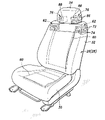
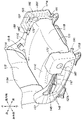
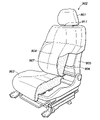
- FIG. 1 is a perspective view of a seat used in an automobile interior temperature control device according to Embodiment 1.
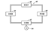
- FIG. 1 is a block diagram showing a refrigerating cycle of an air conditioner used in an automobile interior temperature control device according to Embodiment 1.
- FIG. 1 is a cross-sectional view of an air blowing device used in an automobile interior temperature control device according to Embodiment 1.
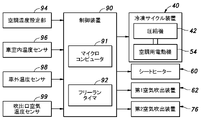
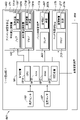
- FIG. 1 is a block diagram showing a control system of a vehicle interior temperature control device according to Embodiment 1.
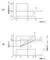
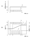
- (A) is a time chart related to power consumption of the automotive interior temperature control device according to Embodiment 1
- (B) is a time chart related to temperature.
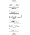
- 4 is a flow chart showing the control flow of the vehicle interior temperature control device according to the first embodiment.
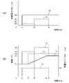
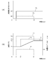
- (A) is a time chart related to power consumption of the automotive interior temperature control device according to Embodiment 2
- (B) is a time chart related to temperature.
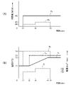
- (A) is a time chart related to power consumption of the automotive interior temperature control device according to Embodiment 3
- (B) is a time chart related to temperature.
- (A) is a time chart related to power consumption of the automotive interior temperature control device according to Embodiment 4
- (B) is a time chart related to temperature.
- (A) is a time chart related to power consumption of the automotive interior temperature control device according to Embodiment 5
- (B) is a time chart related to temperature.
- (A) is a time chart related to power consumption of the automotive interior temperature control device according to Embodiment 6, and (B) is a time chart related to temperature.
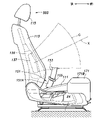
- Schematic diagram of a vehicle equipped with a vehicle seat and an air conditioning system according to Embodiment 7 The side view when the vehicle seat of the air conditioning system according to the seventh embodiment is seen from the outside of the vehicle.
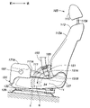
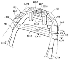
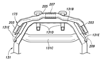
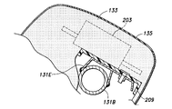
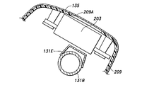
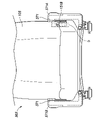
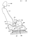
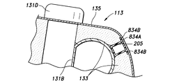
- FIG. 11 is a side view of the vehicle seat according to Embodiment 7 as viewed from the inside of the vehicle; Perspective view of seat back frame and back side air conditioner Back view of seat back frame and back side air conditioner Explanatory drawing for explaining the frame of the headrest and the head-side air conditioner Block diagram of an air conditioning system according to Embodiment 7 Side view of cushion side air conditioner XXIII-XXIII sectional view of FIG. Sectional view of the seatback of the portion corresponding to XXIV-XXIV in FIG. Sectional view of the seatback of the portion corresponding to XXV-XXV in FIG.
- FIG. 12 is an explanatory diagram for explaining the relationship between the deployment region of the side airbag and the cushion-side air conditioner in the vehicle seat of the air conditioning system according to the tenth embodiment;
- Block diagram of an air conditioning system according to Embodiment 13 FIG. 22 is a cross-sectional view of the upper rear end portion of the seat back for explaining the back-side air conditioner according to the fifteenth embodiment;
- FIG. 19 is a front perspective view of a seat provided with a headrest according to a sixteenth embodiment; FIG.
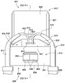
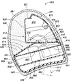
- FIG. 16 is an enlarged perspective view of the headrest according to the sixteenth embodiment as seen from the front The front view of the headrest according to the sixteenth embodiment The perspective view of the headrest according to Embodiment 16 as seen from the rear XXXVI-XXXVI line longitudinal sectional view in FIG. 34 of the headrest according to the sixteenth embodiment
- FIG. 18 is an enlarged perspective view of the headrest according to Embodiment 17 as seen from the front XXVIII-XXXVIII line cross-sectional view in FIG. 37 of the headrest according to Embodiment 17
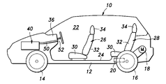
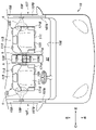
- FIG. 1 shows an electric vehicle 10.
- the electric vehicle 10 includes a vehicle body 12, left and right front wheels 14 and rear wheels 16 attached to the vehicle body 12, an electric motor 18 for driving the rear wheels 16, and a power source for the electric motor 18 provided in the vehicle body 12.
- a rechargeable battery 20 a battery 20 defined by the vehicle body 12, and front and rear seats 26 and 28 mounted on floor panels 24 of the passenger compartment 22.
- the electric vehicle 10 has an air conditioner 40 as an indoor temperature control device.
- the air conditioning system 40 is based on a refrigeration cycle including a refrigerant circuit including a compressor 42, a condenser 44, an expansion valve 46 and an evaporator 48, as shown in FIG.
- the air conditioner 40 is switched between a cooling mode and a heating mode by switching the circulation direction of the refrigerant in the refrigerant circuit, and the air whose temperature is adjusted by heat exchange with the fan air in the condenser 44 or the evaporator 48 is sent to the duct.
- the air is blown into the passenger compartment 22 from an air outlet 52 provided in the instrument panel 36 via an air outlet 50 (see FIG. 1).
- the refrigerating cycle air conditioner 40 can easily obtain an appropriate air conditioning capacity.
- the compressor 42 is driven by the electric motor 54 for air conditioning.
- the power source for the air conditioning motor 54 is shared with the battery 20 that is the power source for the traveling motor 18 .
- the seat cushions 30 and the seat backs 32 of the front seat 26 and the rear seat 28 incorporate a flexible electric sheet heater 60 .
- the seat heater 60 heats up faster than the room temperature rise caused by the air conditioner 40 from the start of energization.
- a pair of left and right first air blowers 62 are incorporated in the upper part of the seat back 32 .
- Each first air blowing device 62 includes an air duct 64, an electric heater 66, an electric fan 68, and a Peltier effect element 70 provided in the middle of the air duct 64, as shown in FIG. 2, air is taken into an air duct 64 from an air intake port 72 opened on the side of the seat back 32, and air is blown out from air outlets 74 opened on both left and right sides of the front surface of the seat back 32 to the neck of the seated person. Blow hot or cold air to the base.
- the air duct 64 can be short, the loss of air pressure flowing through the air duct 64 is small, and the air from the air blowing port 88 toward the neck of the seated person is heated. Air that has been adjusted can be properly blown.
- a pair of left and right second air blowers 76 are incorporated in the upper portion of the headrest 34 .
- Each second air blowing device 76 has substantially the same structure as the first air blowing device 62, and as shown in FIG. 80, an electric fan 82 and a Peltier effect element 84, and as shown in FIG. Hot air or cold air is blown to the neck of the seated person from an air outlet 88 opened to the outside.
- the air duct 78 can be short, the air pressure loss flowing through the air duct 78 is small, and the temperature is controlled from the air blowing port 88 toward the neck of the seated person. air can be properly blown.
- the first air blowing device 62 and the second air blowing device 76 have a rapid heating property in which the temperature rise from the start of energization is faster than the room temperature rise by the air conditioner 40 . Either one of the first air blowing device 62 and the second air blowing device 76 may be switched according to the physique and preference of the seated person.
- the seat heater 60, the first air blowing device 62, and the second air blowing device 76 are all seat temperature control devices, and their power sources are shared with the battery 20, which is the power source of the driving motor 18.
- Each power consumption of the seat heater 60 , the first air blowing device 62 and the second air blowing device 76 is less than the power consumption of the air conditioner 40 . More specifically, the power consumption of each of the seat heater 60, the first air blower 62, and the second air blower 76 is the difference between the power consumption during the rapid heating operation of the air conditioner 40 and the power consumption during normal operation. (increase in power consumption). Furthermore, the total power consumption of the seat heater 60 and the first air blowing device 62 or the second air blowing device 76 is less than the increase in power consumption due to the rapid heating operation.
- the control device 90 of the temperature control device is of an electronic control type that collectively controls the air conditioner 40, the seat heater 60, the first air blowing device 62 and the second air blowing device 76.
- the control device 90 includes a microcomputer 91 and a free-running timer 92, receives various information from each of a vehicle interior temperature setting unit 94, a vehicle interior temperature sensor 96, a vehicle exterior temperature sensor 98, and an outlet temperature sensor 99, and controls the air conditioning motor. 54.
- a control command is output to the seat heater 60, the first air blowing device 62 and the second air blowing device 76 to control them.
- control device 90 controls the set temperature of the control target set by the vehicle interior temperature setting unit 94 and the interior temperature detected by the vehicle interior temperature sensor 96 .
- the air conditioner adjusts the room temperature to the set temperature based on the temperature, the outside temperature detected by the outside temperature sensor 98, and the outlet temperature of the air blown from the air outlet 52 detected by the outlet temperature sensor 99. control 40;
- the air conditioner 40 When the vehicle interior temperature detected by the vehicle interior temperature setting unit 94 is lower than the set temperature, the air conditioner 40 operates in a heating mode in which warm air is blown out, and when the vehicle interior temperature is higher than the set temperature, operates in a cooling mode in which cold air is blown out. works with
- the controller 90 controls the seat heater 60 and the first air blowout for a predetermined period of time. It controls the operation of the device 62 or the second air blowing device 76 .
- the predetermined period during which the seat heater 60 and the first air blowing device 62 or the second air blowing device 76 operate is a period from the time when the air conditioner 40 is activated, which is timed by the free-running timer 92, until the predetermined time elapses. be.
- the predetermined time may be a constant value determined according to the heat capacity of the air conditioner 40 or the like, or a variable value determined according to the difference between the vehicle interior temperature and the set temperature of the air conditioner 40 .
- Embodiment 1 Next, the operation (heating mode) of Embodiment 1 will be described with reference to the time chart shown in FIG. 6 and the flow chart shown in FIG.
- step ST1 when the start switch of the air conditioner 40 is turned on (step ST1: affirmative), the air conditioner 40 is started (step ST2). At the same time, the seat heater 60 and the first air blowing device 62 or the second air blowing device 76 are turned on (step ST3).
- the operating state of the air conditioner 40 at this time is normal operation, and as shown in FIG. 6A, the power consumption Pc of the air conditioner 40 in normal operation is the power value W2.
- the total power consumption Ps of the seat heater 60, which is the seat temperature control device, and the first air blowing device 62 or the second air blowing device 76 (hereinafter sometimes referred to as the power consumption Ps of the seat temperature control device) is It is the power value W1.
- the power value W1 is smaller than the power value W2.
- the seat heater 60 heats up more quickly than the air conditioner 40, and starts warming the buttocks and back of the seated person by heat conduction at time t1.
- the air conditioner 40 is activated, the seated occupant feels the warmth of the buttocks and the back substantially at the same time.
- the first air blowing device 62 or the second air blowing device 76 also has a rapid heating property compared to the air conditioner 40, and as shown in FIG. 6(B), the blown air temperature Hot air having Ts and temperature T4 is blown out from the air outlet 74 or 88 at a predetermined air volume Q1 toward the neck of the seated person.
- the air conditioner 40 warms the neck of the seated person with warm air without causing a substantial delay with respect to activation.
- There is a carotid artery at the neck and warming near the carotid artery is known to have good temperature sensitivity of the body and good heating efficiency. Even if the air volume Q1 is relatively low, the seated person feels sufficiently warm. As a result, the seated occupant quickly obtains a comfortable temperature-related environment substantially at the same time as the start switch of the air conditioner 40 is turned on.
- the air conditioner 40 is ready to blow out air having a temperature necessary for heating, and the air outlet 52 blows hot air having a temperature Tc of temperature T3 to the vehicle. Blow out into the chamber 22 .
- the vehicle interior temperature Ti begins to rise.
- the air conditioner 40 operates so that the vehicle interior temperature Ti becomes the air conditioning set temperature T2.
- step ST4 After a short period of time from time t4, at time t5 when a predetermined time has elapsed since the start of air conditioner 40 (step ST4: Yes), seat heater 60 and first air blowing device 62 or second air The blowout device 76 is turned off (step ST5).
- step ST6 affirmative
- the operation of the air conditioner 40 is stopped (step ST7).
- the integrated value of the total power consumption of the air conditioner 40 and the seat temperature control device during normal operation from time t1 to time t4 is given by (W1+W2) ⁇ (t4 ⁇ t1).
- the power consumption Pc of the air conditioner 40 becomes a power value W3 larger than the power value W2, as indicated by the virtual line in FIG.
- the vehicle interior temperature Ti reaches the air conditioning set temperature T2 at time t3, which is earlier than time t4.
- the integrated value of the power consumption of the air conditioner 40 from time t1 when the rapid heating operation is started to time t3 is W3 ⁇ (t3 ⁇ t1).
- the first embodiment it is possible to quickly obtain a comfortable temperature environment for the occupant and reduce the power consumption of the battery 20 .
- This reduction in power consumption of the battery 20 suppresses reduction in the cruising range of the electric vehicle 10 .
- Embodiment 2 of the indoor temperature control device according to the present invention will be described with reference to FIGS. 8 to 12.
- FIG. 8 to 12 portions corresponding to those in FIG. 6 are denoted by the same reference numerals as those in FIG. 6, and description thereof will be omitted.
- the control device 90 controls the operation period of the first air blowing device 62 or the second air blowing device 76 from time t1 to time t5, which is the first half of the period from time t1 to time t5.
- the blowing air temperature Ts is set to a temperature T5 that is lower than the temperature T4 in the above-described embodiment. Control is performed so that the temperature T6 is higher than the temperature T6.
- the power consumption Ps of the seat temperature control device in the period from time t1 to time t5 is a power value W4 lower than the power value W1
- the power consumption Ps in the period from time t5 to time t6 is higher than the power value W1.
- the hot warm air does not hit the neck of the seated person from the beginning of the blowing, which improves comfort. improves.
- the temperature Ts of the hot air blown out from the air outlet 74 or 88 may rise stepwise or continuously over time.
- Embodiment 3 In Embodiment 3 shown in FIG. 9, the control device 90 controls the operation period of the first air blowing device 62 or the second air blowing device 76 from time t1 to time t5, which is the first half of the period from time t1 to time t5. At t6, the air volume Q of the blown air is set to Q2, which is smaller than the air volume Q1 in the above-described embodiment. Control is performed to increase the air volume Q3.
- the power consumption Ps of the sheet temperature control device in the period from time t1 to time t5 is a power value W6 lower than the power value W1
- the power consumption Ps in the period from time t5 to time t6 is higher than the power value W1.
- the air volume Q of the warm air blown out from the air outlet 74 or 88 is smaller in the first half of the blowing than in the latter half, the warm air does not hit the neck of the seated person with a large air volume from the beginning of the blowing, which makes it comfortable. improve sexuality.
- the air volume Q of the hot air blown out from the air outlet 74 or 88 may increase stepwise or continuously over time.
- Embodiment 4 In Embodiment 4 shown in FIG. 10, the control device 90 intermittently operates the first air blowing device 62 or the second air blowing device 76 to repeat turning on and off from time t1 to time t5. control.
- the average value of the power consumption Ps of the seat temperature control device including the first air blowing device 62 or the second air blowing device 76 during the period from time t1 to time t6 is reduced compared to the case of continuous operation. do.
- Embodiment 4 the power consumption of the battery 20 is further reduced, and it is possible to quickly obtain a comfortable temperature environment for the occupants and to reduce the power consumption of the battery 20 .
- control device 90 controls the power consumption Pc to be higher than the power value W2 during normal operation from the start of the air conditioner 40 until the vehicle interior temperature Ti reaches the air conditioning set temperature T2. Control is performed to operate the air conditioner 40 with the small power value W4.
- the time when the vehicle interior temperature Ti reaches the air conditioning set temperature T2 is delayed from time t4 to time t7.
- the timing at which the seat temperature control device by the seat heater 60 and the first air blowing device 62 or the second air blowing device 76 is turned off is also delayed from time t5 to time t8.
- the time required for the vehicle interior temperature Ti to reach the air conditioning set temperature T2 after the start of the air conditioner 40 is long. , the load on the battery 20 is reduced during this period, and the heat generation of the battery 20 is suppressed.
- the seat heater 60 and the first air blowing device 62 or the second air blowing device 76 are operating even if the time required for the vehicle interior temperature Ti to reach the air conditioning set temperature T2 after the start of the air conditioner 40 is long. As a result, the comfortable environment for the occupant regarding temperature does not deteriorate.
- Embodiment 5 the heat generation of the battery 20 is suppressed, and both the comfortable temperature environment for the occupant and the reduction of the power consumption of the battery 20 are achieved.
- the control device 90 controls the period from time t1 when the air conditioner 40 is started up to when the difference between the air conditioning set temperature T2 of the air conditioner 40 and the vehicle interior temperature Ti is equal to or greater than a predetermined value.
- the seat heater which is the temperature control device for the seat 60 and the first air blowing device 62 or the second air blowing device 76 are controlled to operate.
- the seat temperature control device is turned off before time t4 when the vehicle interior temperature Ti reaches the air conditioning set temperature T2 of the air conditioner 40, or the vehicle interior temperature Ti reaches the air conditioning set temperature T2 of the air conditioner 40.
- the seat temperature control device will not be turned on after time t4 when the temperature is turned on.
- the sixth embodiment it is possible to quickly obtain a comfortable temperature environment for the occupant and reduce the power consumption of the battery 20 without over- or under-activating the seat temperature control device.
- the controller 90 controls the air conditioner 40 to operate for a predetermined period of time when the air conditioner 40 is started, as in the heating mode. It controls the operation of the sheet temperature control device.
- the Peltier effect elements 70, 84 of the first air blowing device 62 or the second air blowing device 76 act as a seat temperature control device instead of the electric heaters 66, 80, and the air blowing ports 74, 88 are operated. Cold air is blown toward the neck of the seated person.
- the heat source of the seat heater 60, the first air blowing device 62, and the second air blowing device 76 is not limited to an electric heating type using Joule heat, and may be a ceramic heater or the like.
- the air conditioner 40 may be based on a motorized Stirling Cyclo.
- the seat heater 60 is not essential, and the seat temperature control device may have either one of the first air blowing device 62 and the second air blowing device 76 .
- Embodiment 7 A vehicle seat and an air conditioning system according to Embodiment 7 will be described with reference to FIGS. 13 to 2.
- FIG. 13 A vehicle seat and an air conditioning system according to Embodiment 7 will be described with reference to FIGS. 13 to 2.
- FIG. 13 A vehicle seat and an air conditioning system according to Embodiment 7 will be described with reference to FIGS. 13 to 2.
- FIG. 13 A vehicle seat and an air conditioning system according to Embodiment 7 will be described with reference to FIGS. 13 to 2.
- the vehicle 10 is a four-wheeled automobile.
- the vehicle 10 is provided with a passenger compartment 22 serving as a passenger compartment.
- Vehicle seats 103 constituting a driver's seat and a front passenger's seat are arranged side by side in the vehicle compartment 22 .
- the vehicle seat 103 has a seat body 105 on which a seated person sits.
- the seat body 105 is placed on the floor panel 24 defining the bottom of the vehicle compartment 22 so that the seated occupant faces the front of the vehicle 10 .
- the front/rear, left/right, and up/down directions are defined and described.
- the vehicle seat 103 constitutes a driver's seat located on the right side of the front row.
- a door 107 is provided on the vehicle outer side of the seat body 105 .
- a door trim 107A is provided on the side surface of the door 107 on the inside of the vehicle.
- the door trim 107A is a lining component of the door 107 and covers the door panel 107B from the inside of the vehicle.
- the door trim 107A constitutes armrests and door pockets.
- the door 107 is provided with a door airbag 108 that inflates toward the inside of the vehicle (the inside of the vehicle interior 22) and can be deployed to the outside of the vehicle of the seated person.
- the door airbag 108 is housed between the door trim 107A and the door panel 107B.
- a region through which the door airbag 108 passes when the door airbag 108 deploys (hereinafter referred to as a deployment region A) is hatched with dots.
- a center console box 109 is provided on the inside of the seat body 105 .
- the center console box 109 includes a storage recess 109A that opens to store articles, and a lid 109B that opens and closes the storage recess 109A.
- the lid 109B is hinged to the opening edge 109C of the housing recess 109A.
- the housing recess 109A is recessed downward and opens upward.
- the lid body 109B is hinged to the opening edge of the housing recess 109A and to the portion on the outside of the vehicle.
- the area through which the lid 109B is opened and closed, that is, the movable area B is hatched with oblique lines.
- the seat main body 105 includes a seat cushion 111 that supports the buttocks of the seated person, a seat back 113 provided at the rear of the seat cushion 111 and functioning as a backrest, and a seat back 113.
- a headrest 115 is provided on the top.
- the seat cushion 111 has a substantially rectangular parallelepiped shape with a surface facing in a substantially vertical direction.
- the upper surface of the seat cushion 111 constitutes a seating surface 111A for one passenger.
- the seating surface 111A is recessed downward at substantially the center in the left-right direction and is slightly downwardly inclined rearward.
- the buttocks are arranged on the rear portion of the seating surface 111A, and the thighs are arranged on the front portion of the seating surface 111A.
- the seat cushion 111 constitutes a center portion in the left-right direction, and is connected to a base portion 111B having a substantially horizontal upper surface and both left and right edges of the base portion 111B.
- a bank portion 111C also referred to as a bolster portion protruding upward from the upper surface is provided.
- the seat back 113 has a substantially rectangular parallelepiped shape that extends vertically and has surfaces facing substantially in the front-rear direction.
- the front surface of the seat back 113 constitutes a support surface 113A facing the back of the seated person.
- the support surface 113A is recessed rearward at substantially the center in the left-right direction, and is inclined slightly rearward upward.
- the support surface 113A supports the back of the occupant leaning against the seat back 113 from behind.
- the headrest 115 is connected to the upper end of the seat back 113 via two pillars 115A.
- the headrest 115 is positioned behind the head of the seated person.
- the seat cushion 111 includes a metal frame 121 (also referred to as a seat cushion frame; see FIG. 16) forming a skeleton, a pad member 123 supported by the frame 121, and an outer skin covering at least a portion of the surface of the pad member 123. material 125;
- the frame 121 of the seat cushion 111 includes a pair of left and right side frames 121A extending back and forth, a front frame (not shown) connecting front portions of the two side frames 121A, and a rear frame (not shown) connecting rear portions of the two side members. shown).
- the frame 121 further includes a plate-shaped pan frame 121B that is provided between the two side frames 121A and spans the front and rear members.
- the pad member 123 is arranged on the upper surface of the pan frame 121B.
- the side frames 121A of the seat cushion 111 are provided with side covers 127, respectively.
- the side cover 127 is a member made of resin and extends back and forth along the side frame 121A.
- the side cover 127 has a shape matching the side frame 121A and covers the side frame 121A from the outside of the seat.
- the side cover 127 on the outside of the vehicle is provided with a concave portion 127A recessed inward of the seat.
- two lower rails 129 are provided below the seat cushion 111 and extend forward and backward.
- An upper rail 130 extending forward and backward is provided on each lower rail 129 .
- the upper rail 130 is connected to the lower rail 129 so as to be slidable back and forth.
- Each upper rail 130 is connected to a frame 121 forming the skeleton of the seat cushion 111 .
- a link member (not shown) is provided between the upper rail 130 and the lower rail 129 in the seventh embodiment. By rotating the link member, the height and inclination of the seat cushion 111 with respect to the floor panel 24 can be changed.
- the seat back 113 includes a metal frame 131 that forms a skeleton like the seat cushion 111, a pad member 133 supported by the frame 131, and a skin material 135 that covers at least part of the surface of the pad member 133.
- the frame 131 of the seat back 113 includes a pair of left and right side frames 131A extending vertically, an upper frame 131B that spans between upper portions of the side frames 131A, and a pair of side frames 131A. It has a lower frame (not shown) that spans between the lower parts and forms a substantially square frame shape.
- a cross frame 131C is provided to connect the left side and the right side of the upper frame 131B.
- the left side frame 131A of the seat back 113 is supported at its lower end by the rear end of the left side frame 131A of the seat cushion 111 so as to be rotatable about the tilting axis P (see FIG. 2).
- the right side frame 131A of the seat back 113 is rotatably supported around the tilting axis P at the rear end of the right side frame 131A of the seat cushion 111 at its lower end.
- the frame 131 of the seat back 113 is connected to the frame 121 of the seat cushion 111 so as to be tiltable.
- An airbag module 136 is provided on the side frame 131A of the seatback 113, which is on the outside of the vehicle.
- the airbag module 136 has a side airbag 137 that deploys to the outside of the vehicle of the seated person in the event of a side collision.
- a two-dot chain line indicates a region through which the side airbag 137 passes when deployed.
- the area through which the side airbag 137 passes during deployment will be referred to as a deployment area C of the side airbag 137 .
- the upper frame 131B of the seat back 113 is provided with two pillar guides 131D for receiving the pillars 115A of the headrest 115 (see FIG. 14).
- Each pillar guide 131D has a tubular shape extending substantially parallel to the extending direction of the side frame 131A of the seatback 113. As shown in FIG.
- the headrest 115 has a metal frame 139 forming a skeleton, a pad member 141 supported by the frame 139, and a skin material 143 covering the surface of the pad member 141.
- the frame 139 has a pair of left and right vertical frames 139A each having a cylindrical shape, and an auxiliary frame 139B (also referred to as a bracket) that extends left and right and connects the two vertical frames 139A.
- the lower end portions of the vertical frames 139A respectively constitute pillars 115A.
- the headrest 115 is supported on the upper end of the seatback 113 by inserting the pillars 115A into the pillar guides 131D.
- the auxiliary frame 139B preferably has a substantially flat support surface 139C that faces forward and overlaps the left and right vertical frames 139A in a front view.
- the seat cushion 111 is provided with a reclining lever 145 for tilting the seat back 113 with respect to the seat cushion 111 and a height lever 147 for changing the height of the seat cushion 111 .
- Each of the reclining lever 145 and the height lever 147 is supported at its rear end by the side frame 121A of the seat cushion 111 and extends forward outside the seat of the side frame 121A.
- a front portion of the reclining lever 145 and a front portion of the height lever 147 are respectively provided with a grip portion 149 that receives an operation input from the seated person. That is, each of the grip portions 149 functions as an operation input portion that receives an operation input related to deformation and displacement of the seat body 105 from the seated person.
- the reclining lever 145 and the height lever 147 are provided on the outside of the seat cushion 111 .
- Each grip portion 149 is received in a concave portion 127A of the side cover 127. As shown in FIG.
- the seat body 105 is provided with a buckle device 151 for a seat belt.
- the buckle device 151 engages with a seat belt tongue 155 held by the seat belt 153 to restrain the seat occupant to the seat body 105 .
- the buckle device 151 has a buckle support arm 151A and a buckle 151B.
- the buckle support arm 151A has a bar shape extending back and forth.
- the buckle support arm 151A is coupled at its rear end to the rear portion of the side frame 121A of the seat cushion 111 so as to be rotatable about a rotation axis X extending in the left-right direction.
- the buckle 151B is detachably attached to the seatbelt tongue 155 and fixed to the front end of the buckle support arm 151A.
- the buckle support arm 151A When in use, the buckle support arm 151A is arranged to extend obliquely forward and upward, and the buckle 151B is coupled to the seat belt tongue 155 as shown in FIG.
- the buckle 151B is supported by the side frame 121A of the seat cushion 111 so as to be rotatable about the rotation axis X extending in the left-right direction.
- the movement range of the buckle 151B when the buckle support arm 151A is rotated within the movable range about the rotation axis X that is, the movable range D of the buckle 151B is hatched with dots. ing.
- a range of motion D of the buckle 151B forms a fan-shaped ring (fan surface shape) centering on the rotation axis X.
- the buckle 151B is movably supported in this way, the seat occupant can arrange the buckle 151B at a position where he or she can easily operate it, and can easily connect the seat belt tongue 155 to the buckle 151B.
- the seat belt 153 is introduced into the passenger compartment 22 from near the upper end of the center pillar 159 via the interior of the center pillar 159 from a seat belt retractor device (not shown) fixed to the vehicle body.
- a seat belt retractor device (not shown) fixed to the vehicle body.
- the seat belt 153 By pulling out the seat belt 153 and engaging the seat belt tongue 155 with the buckle 151B, the seated occupant is restrained by the seat body 105.
- the movement area E of the seat belt tongue 155 when the buckle support arm 151A is rotated within the movable range about the rotation axis X is hatched.
- the vehicle seat 103 is provided with an air conditioning system 161 .
- the air conditioning system 161 has a seat air conditioner 163 .
- the seat air conditioner 163 sends cool/warm air toward the seated person to adjust the temperature of the air around the seated person.
- the seat air conditioner 163 includes a seating sensor 165, a temperature sensor 167, a cushion side air conditioner 171 provided on the seat cushion 111, a back side air conditioner 173 provided on the seat back 113, and a headrest 115.
- a head-side air conditioner 175 and a controller 181 are included.
- a seating sensor 165 is provided on the vehicle seat 103 and detects whether or not a person is seated on the vehicle seat 103 .
- the seating sensor 165 may be configured by a pressure sensor that detects pressure applied to the seating surface 111A, or may be configured by one or more membrane switches that are turned on when the occupant sits on the seat.
- the temperature sensor 167 is a sensor for acquiring the temperature inside the passenger compartment 22 of the vehicle 10, and is preferably composed of a thermistor that acquires the temperature based on a change in resistance value. Temperature sensor 167 may be provided on vehicle seat 103 , or may be provided on a wall or the like that defines compartment 22 .
- the cushion-side air conditioners 171 are provided on the vehicle outer side and the vehicle inner side of the seat cushion 111 .
- the cushion-side air conditioners 171 provided on the inner side and the outer side of the vehicle each have a substantially rectangular parallelepiped shape and are bilaterally symmetrical to each other.
- the cushion-side air conditioners 171 are provided on the left and right sides of the front end of the seat cushion 111, respectively.
- the cushion-side air conditioners 171 provided inside and outside the vehicle are arranged at symmetrical positions of the seat cushion 111 .
- the cushion-side air conditioner 171 located inside the vehicle will be referred to as a vehicle-inside air conditioner 171A
- the cushion-side air conditioner 171 located outside the vehicle will be referred to as an outside air-conditioner 171B.
- the vehicle-interior air conditioner 171A and the vehicle-exterior air conditioner 171B each include a projection 172 projecting inwardly of the seat (toward the seat cushion 111) at the upper part of the inner side of the seat.
- the pad member 123 of the seat cushion 111 is provided with notches 183 that are notched inward of the seat at the upper ends of the left and right sides of the front end.
- the cushion-side air conditioner 171 is received in the notch 183 at the projection 172 and fixed to the side frame 121A of the seat cushion 111 .
- the wall surface defining the notch 183 of the pad member 123 and the outer surface of the cushion-side air conditioner 171 are sufficiently separated from each other, and the portion corresponding to the notch 183 of the seat cushion 111 and the outer surface of the cushion-side air conditioner 171 are separated.
- a gap 185 is provided between them.
- the cushion-side air conditioner 171 includes an air intake port 187 provided on the outer side surface of the seat, an inner air blowing port 189 provided on the inner side surface of the seat, and a lower front end portion. and a lower air outlet 191 which is provided.
- the intake port 187 opens toward the outside of the seat.
- the inner air blowing port 189 is provided at the rear upper end (more specifically, the projection 172) of the side surface inside the seat, and opens toward the inside of the seat.
- the lower air blowing port 191 opens forward toward the inside of the seat.
- the cushion-side air conditioner 171 draws in air from the intake port 187 , cools or heats the drawn-in air, and blows it out from the inner blowing port 189 and the lower blowing port 191 .
- the air blown from the inner air outlet 189 reaches the thighs of the seated person and adjusts the ambient temperature of the thighs of the seated person.
- the air blown out from the lower air outlet 191 adjusts the temperature around the back of the knees and calves of the seated person. In this way, the cushion-side air conditioner 171 blows cool air or warm air onto the legs of the seated person, thereby controlling the temperature around the legs.
- the cushion-side air conditioner 171 includes a blower 193, a duct 195, a temperature controller 197 and a cover member 201, as shown in detail in FIGS.
- the blower 193 is a so-called blower that sucks in air through an inlet and blows out air through an outlet.
- the blower 193 has a suction port connected to the suction port 187 and a discharge port connected to the duct 195 .
- the blower 193 sends the air sucked from the intake port 187 into the duct 195 .
- the duct 195 has a tubular shape (a square tubular shape in the seventh embodiment). One end of duct 195 is connected to blower 193 . The other end of the duct 195 is bifurcated. One of the other ends of the duct 195 extends inwardly and upwardly of the seat and is connected to the inner air outlet 189 . The other end of the duct 195 extends downward, then extends toward the inside of the seat, bends, and further extends forward in a direction that inclines toward the inside of the seat. The other end of the duct 195 reaches the front side of the front end of the seat cushion 111 . The other end of the duct 195 forms a lower air outlet 191 with an opening downward from the upper surface of the embankment 111 ⁇ /b>C and sloping forward and inward of the seat.
- the ends of the duct 195 on the other end side are located further inside the seat than the left and right ends of the seat cushion 111 when viewed from the front. Further, as shown in FIG. 15, the other end of the duct 195, that is, the front end thereof, reaches the front side of the front end of the seat cushion 111. As shown in FIG. Thereby, the air sent out from the blower 193 can be effectively guided to the feet of the seated person. Further, as shown in FIG. 16, since the front end of the duct 195 is positioned below the bank portion 111C, when the thighs of the seated person are placed on the bank portion 111C It is difficult for the duct 195 to come into contact with the part.
- the ducts 195 are located inside the seat from the left and right ends of the side covers 127, respectively. As a result, the side cover 127 can oppose the colliding object to the left and right side surfaces of the seat cushion 111 before the duct 195, so that the duct 195 can be protected against the colliding object.
- the temperature control device 197 is a device for heating and cooling (adjusting the temperature) to generate cool air or warm air, and includes a heat source 197A (also referred to as a temperature control device main body) that generates or absorbs heat.
- a heat source 197A also referred to as a temperature control device main body
- the temperature control device 197 is provided downstream of the blower 193 and at the branched portion of the duct 195 .
- the air sucked by the blower 193 is cooled or heated by the heat source 197A of the temperature control device 197 and reaches the inner air blower port 189 and the lower air blower port 191 .
- the heat source 197A is preferably composed of a so-called Peltier element that can be cooled and heated by electric current.
- the cover member 201 is a substantially rectangular parallelepiped member covering the blower 193 , the temperature control device 197 and the duct 195 .
- the cover member 201 corresponds to a case that accommodates the blower 193, the temperature control device 197 and the duct 195 inside.
- the cover member 201 is arranged so as to have a surface facing the left-right direction.
- the cover member 201 has an inner cover 201A forming the inner side of the seat, and an outer cover 201B forming the inner upper portion of the seat and the outer side of the seat.
- the inner cover 201A constitutes the seat inner side wall of the cover member 201, the front and rear, and the upper half of the upper wall, which are the seat inner side portions.
- the inner cover 201A is joined to the side surface of the side frame 121A of the seat cushion 111 on the outside of the seat.
- a metal plate-shaped bracket 202B is fixed to the seat outer surface of the side frame 121A of the seat cushion 111 via a metal wire 202A.
- the inner cover 201A is coupled to and supported by the side frame 121A of the seat cushion 111 by being fixed to the bracket 202B.
- a notch portion 201C cut from above is provided on the side wall of the inner cover 201A on the inner side of the seat.
- the notch 201C is positioned at the upper end of the side wall on the inner side of the seat.
- the cutout portion 201C constitutes the lower portion of the inner blowing port 189. As shown in FIG.
- the outer cover 201B constitutes the side walls outside the seat of the cover member 201, the upper parts of the front, rear and upper walls outside the seat, and the lower half of the front wall.
- the outer cover 201B is joined to the inner cover 201A.
- a wire 202C extending outward of the vehicle is provided on the bracket 202B to which the inner cover 201A is coupled.
- the outer cover 201B is provided with a locking claw 202D that can be engaged with the wire 202C, and the locking claw 202D is engaged with the wire 202C to couple the outer cover 201B to the bracket 202B.
- the outer cover 201B is coupled to the inner cover 201A via the bracket 102B.
- outer cover 201B may be provided with locking claws (not shown), and the outer cover 201B may be coupled to the inner cover 201A by locking the locking claws to the inner cover 201A.
- a plate-like extension 201D extending inward from the inner edge of the seat is provided at the upper end of the outer cover 201B so as to fit into the notch 201C.
- the extension 201D seals the notch 201C from above.
- the extending portion 201D constitutes the upper edge of the inner blowing port 189.
- the cutout portion 201C and the extension portion 201D form the inner air blowing port 189.
- One end of the duct 195 is fixed to the exhaust port of the blower 193, the other end is bifurcated, and one end of the duct 195 is fitted to the inner air blow port 189 and connected.
- a through hole 201E is provided in the lower half of the front wall of the outer cover 201B.
- the other end of the duct 195 extends forward, passes through the through hole 201E, and further extends inwardly of the seat in an inclined direction.
- a side wall of the outer cover 201B on the outside of the seat (the portion constituting the side wall of the cover member 201 on the outside of the seat) is provided with a through hole 201F penetrating in the left-right direction.
- the through hole 201 ⁇ /b>F constitutes an intake port 187 .
- a blower 193 is fixed to the side surface of the outer cover 201B on the inner side of the seat by tapping or screwing at a position aligned with the through hole 201F.
- the temperature control device 197 is housed and fixed inside the duct, but is not limited to this mode.
- duct 195 is fixed to outer cover 201B by being fixed to blower 193, but duct 195 may be directly connected to outer cover 201B or may be connected to inner cover 201A.
- the back side air conditioner 173 has two left and right blowers 203 arranged at both left and right ends of the upper frame 131B of the seat back 113, and extends inward from the two blowers 203, respectively. , a duct 205 having an air outlet 206 that opens forward in the central portion in the left-right direction, and a temperature control device 207 provided in the duct 205 at a position corresponding to the air outlet 205A.
- the left and right blowers 203 are provided at portions corresponding to the shoulders of the seat back 113, respectively. Each blower 203 sucks air from the outside of the seat back 113 and feeds air into the duct 205 .
- the temperature control device 207 is arranged at the upper end portion of the seat back 113 .
- the temperature control device 207 is a device for heating/cooling to generate cool air or warm air, and includes a heat source 207A that generates or absorbs heat.
- the heat source 207A is also preferably composed of a so-called Peltier element that can be cooled and heated by electric current.
- the air sent into the duct 205 is cooled or heated by the heat source 207A of the temperature control device 207, and blows out from the air outlet 205A toward the neck of the seated person. This regulates the ambient temperature around the neck of the seated person.
- the heat source 207A is positioned behind the pillar guide 131D.
- a fixing bracket 131E is fixed to the upper frame 131B by welding or the like.
- the blower 203 and the duct 205 are arranged along the upper part of the rear surface of the upper frame 131B.
- a resin garnish 209 also called a cover member
- the duct 205, upper frame 131B and blower 203 are covered with a garnish 209 from behind.
- the blower 203 is fixed to the garnish 209 by tapping. Thereby, the duct 205 connected to the blower 203 is also fixed to the garnish 209 .
- the garnish 209 is screwed to the fixing bracket 131E (see FIG. 24).
- the back side air conditioner 173 is fixed to the upper frame 131B of the seat back 113 by fixing the garnish 209 to the fixing bracket 131E.
- the garnish 209 is directly covered from the back by a skin material 135 on the upper left and right sides of the seat back 113, and a pad member 133 is provided between the garnish 209 and the skin material 135. Not done.
- the fixing bracket 131E is covered with a pad member 133 and a skin material 135 from left and right sides as shown in FIG.
- a ventilation hole 209A is provided in the garnish 209 at a position corresponding to the blower 203.
- the portion of the skin material 135 corresponding to the ventilation hole 209A and the portion corresponding to the opening of the duct 205 may be formed in a mesh shape.
- the head-side air conditioner 175 includes a passage forming member 211 defining an air passage 210 extending in the front-rear direction, a blower 213 arranged in the air passage 210, and a blower 213 arranged in the air passage 210.
- a temperature control device 217 is provided.
- the passage forming member 211 is coupled to the frame 139 of the headrest 115 .
- the passage forming member 211 is coupled to the auxiliary frame 139B from below and defines an air passage 210 that slopes downward toward the front.
- the blower 213 sucks air from the back side of the headrest 115 and sends the air into the air passage 210 .
- the temperature control device 217 is a device for heating and cooling to produce cold air and warm air in cooperation with the blower 213, and includes a heat source 217A that generates or absorbs heat. .
- the heat source 217A is also preferably composed of a so-called Peltier element that can be cooled and heated by electric current.
- the temperature control device 217 is arranged on the front side of the blower 213, that is, on the downstream side. The air sent forward by the blower 213 is cooled or heated by the heat source 217A of the temperature control device 217 and reaches the head of the seated person. This regulates the ambient temperature of the seated person's head.
- portions of the skin material 143 corresponding to the inlet and outlet of the air passage 210 may be formed in a mesh shape.
- control device 181 is composed of a microcomputer including a central processing unit (CPU 181A), a RAM 181B, a ROM 181C, and a storage device 181D composed of an SSD, HDD, or the like.
- CPU 181A central processing unit
- RAM 181B random access memory
- ROM 181C read-only memory
- storage device 181D composed of an SSD, HDD, or the like.
- the control device 181 controls driving of the seat air conditioner 163 based on the presence or absence of a seated person acquired by the seating sensor 165 and the temperature inside the vehicle compartment 22 acquired by the temperature sensor 167 .
- the control device 181 drives the cushion-side air conditioner 171 to cool the seated occupant. Specifically, the control device 181 drives the blowers 193 of the vehicle interior air conditioner 171A and the vehicle exterior air conditioner 171B, and controls the temperature control device 197 (heat source 197A) to cool the air sent out by the blower 193. to drive.
- the control device 181 controls so that the output of the vehicle-exterior air conditioner 171B is greater than the output of the vehicle-interior air conditioner 171A.
- the output referred to here means the amount of change in the temperature of the air blown out by the blower 193 due to the heat source 197A, and indicates the amount of change in the temperature of the air when the heat source 197A is stopped, that is, the temperature difference.
- the control device 181 controls the heat source 197A of the vehicle-exterior air conditioner 171B so that the air from the blower 193 is cooled more than the heat source 197A of the vehicle-interior air conditioner 171A (that is, the temperature drop amount is control to increase).
- the control device 181 may drive the back side air conditioner 173 and the head side air conditioner 175 at the same time. However, the control device 181 controls the output of the vehicle-exterior air conditioner 171B to be greater than the output of both the back-side air conditioner 173 and the head-side air conditioner 175 . That is, the control device 181 compares the heat source 197A of the vehicle-exterior air conditioner 171B with both the heat source 207A of the back-side air conditioner 173 and the heat source 217A of the head-side air conditioner 175, and the heat source 217A of the head-side air conditioner 175 from the corresponding blowers 193, 203, 213. Control is performed so that the air is cooled more (that is, the amount of temperature drop is increased). At this time, the control device 181 may control the output of the back-side air conditioner 173 to be higher than the output of the head-side air conditioner 175 .
- the control device 181 drives the cushion-side air conditioner 171 to warm the seated occupant. Specifically, the control device 181 drives the blowers 193 of the vehicle-interior air conditioner 171A and the vehicle-exterior air conditioner 171B, respectively, and drives the heat sources 197A to heat the air sent out by the blowers 193, respectively.
- control device 181 controls so that the output of the vehicle-exterior air conditioner 171B is greater than the output of the vehicle-interior air conditioner 171A. Specifically, the control device 181 controls the heat source 197A of the vehicle-exterior air conditioner 171B so that the air from the blower 193 is warmed more than the heat source 197A of the vehicle-inside air conditioner 171A (that is, the temperature rise amount is control to increase).
- control device 181 may drive the back side air conditioner 173 and the head side air conditioner 175 at the same time. However, the control device 181 controls the output of the vehicle-exterior air conditioner 171B to be greater than the output of both the back-side air conditioner 173 and the head-side air conditioner 175 . That is, the control device 181 compares the heat source 197A of the vehicle-exterior air conditioner 171B with both the heat source 207A of the back-side air conditioner 173 and the heat source 217A of the head-side air conditioner 175, and the heat source 217A of the head-side air conditioner 175 from the corresponding blowers 193, 203, 213. Control is performed so that the air is warmed more (that is, the amount of temperature rise is increased). At this time, the control device 181 may control the output of the back-side air conditioner 173 to be higher than the output of the head-side air conditioner 175 .
- the vehicle-interior cushion-side air conditioner 171 is coupled to the seat cushion 111 outside the movable range D of the buckle 151B in a side view. Further, in this embodiment, the cushion-side air conditioner 171 on the inside of the vehicle is located outside the movement area E of the seat belt tongue 155 engaged with the buckle 151B. In addition, as shown in FIG. 4, the vehicle-interior cushion-side air conditioner 171 (vehicle-inside air conditioner 171A) is arranged at a position overlapping the range of motion D of the buckle 151B in a front view.
- the cushion-side air conditioner 171 (vehicle-exterior air conditioner 171B) is located forward of the rear end of the grip portion 149 of the reclining lever 145 and of the rear end of the grip portion 149 of the height lever 147. placed forward.
- the cushion-side air conditioner 171 is arranged forward of the front end of the grip portion 149 of the reclining lever 145 and forward of the front end of the grip portion 149 of the height lever 147 .
- the cushion-side air conditioner 171 is provided in front of any of the grip portions 149 (operation input members) for the seated person to perform operation input to change the position and shape of the vehicle seat 103. is preferred. Accordingly, the seated person can easily perform operation input to the grip portion 149 without being obstructed by the cushion-side air conditioner 171 .
- the position corresponding to the grip portion 149 is indicated by a two-dot chain line.
- any of the left and right outer ends of the grip portion 149 (operation input member) for the seated person to perform operation input to change the position and shape of the vehicle seat 103 is positioned outside the vehicle.
- the outer end of the cushion-side air conditioner 171 (vehicle-exterior air conditioner 171B) in the seat outward direction is the seat outer end of the grip portion 149 of the reclining lever 145, and the height lever 147 is gripped. It is located on the inner side of the seat than any of the outer ends of the portion 149 in the seat outer direction.
- the left-right direction outer end of the grip portion 149 is positioned further outside the seat than the left-right direction outer end of the cushion-side air conditioner 171 . Therefore, the seated person can easily perform operation input to the grip portion 149 without being obstructed by the cushion-side air conditioner 171 inside the vehicle.
- the cushion-side air conditioner 171 (vehicle-exterior air conditioner 171B) is located forward of the front end of the deployment area C of the side airbag 137 .
- the vehicle-exterior cushion-side air conditioner 171 is located outside the deployment area of the side airbag 137 .
- the rear edge of the cushion-side air conditioner 171 (vehicle-exterior air conditioner 171B) is located in front of the deployment area A of the door airbag . Accordingly, the cushion-side air conditioner 171 is positioned outside the deployment area A of the door airbag 108 . Therefore, it is possible to prevent the deployment of the door airbag 108 from being hindered by the cushion-side air conditioner 171 on the outside of the vehicle. Further, the cushion-side air conditioner 171 inside the vehicle is located outside the range of motion B of the lid 109B. Accordingly, it is possible to prevent the movement of the lid 109B from being hindered by the cushion-side air conditioner 171 inside the vehicle.
- the vehicle seat 103 is provided with a cushion-side air conditioner 171 for adjusting the temperature of the legs of the seated person.
- the vehicle-interior cushion-side air conditioner 171 is coupled to the seat cushion 111 outside the range of motion D of the buckle 151B. Accordingly, it is possible to prevent the movement of the buckle 151B from being hindered by the cushion-side air conditioner 171 inside the vehicle.
- the vehicle interior air conditioner 171A (the vehicle interior cushion side air conditioner 171) is arranged at a position overlapping the range of motion D of the buckle 151B when viewed from the front.
- the width of the vehicle seat 103 in the left-right direction can be made smaller than when the vehicle interior air conditioner 171A does not overlap the range of motion D in a front view. Therefore, the vehicle seat 103 can be downsized.
- the vehicle interior air conditioner 171A (the vehicle interior cushion side air conditioner 171) is arranged outside the movement area E of the seat belt tongue 155 engaged with the buckle 151B. This prevents the movement of the seat belt tongue 155 from being hindered.
- the cushion-side air conditioners 171 (vehicle interior air conditioner 171A and vehicle exterior air conditioner 171B) are received in notches 183 provided in the pad member 123 of the seat cushion 111, respectively.
- the width of the vehicle seat 103 in the left-right direction can be reduced and the size of the vehicle seat 103 can be reduced as compared with the case where the notch 183 is not provided in the pad member 123 .
- a gap 185 is provided between the seat cushion 111 and the cushion-side air conditioner 171 by providing the notch 183 in the pad member 123 . Therefore, the cushion-side air conditioner 171 and the pad member 123 do not come into contact with each other, and heat can be prevented from being transferred from the cushion-side air conditioner 171 to the pad member 123 .
- the heat source 207A of the back side air conditioner 173 is located behind the pillar guide 131D. Therefore, when a rearward load is applied to the seated person, the pillar guide 131D and the pillar 115A hinder the rearward movement of the seated person's neck, thereby preventing the seated person's neck from approaching the heat source 207A.
- the control device 181 controls driving of the seat air conditioner 163 based on the temperature inside the vehicle interior 22 acquired by the temperature sensor 167 . Accordingly, the vehicle seat 103 can be air-conditioned based on the temperature inside the vehicle compartment 22 where the person seated in the vehicle seat 103 is. Therefore, the driving of the seat air conditioner 163 can be controlled so as to match the sensible temperature of the seated person.
- the control device 181 drives the cushion-side air conditioner 171 to apply cool air to the legs of the seated person, thereby cooling the legs of the seated person. Cool the part.
- the controller 181 controls the heat source 197A of the vehicle exterior air conditioner 171B so that the air from the blower 193 is cooled more than the heat source 197A of the vehicle interior air conditioner 171A. As a result, the legs of the seated person are cooled more from the outside of the vehicle than from the inside of the vehicle.
- the control device 181 drives the cushion-side air conditioner 171 to apply warm air to the legs of the seated person. Warm up your legs.
- the controller 181 controls the heat source 197A of the vehicle exterior air conditioner 171B so that the air from the blowers 193, 203, 213 is warmer than the heat source 197A of the vehicle interior air conditioner 171A.
- the legs of the seated person are warmed more from the outside of the vehicle than from the inside of the vehicle.
- Seated occupants are easily affected by the outside temperature on the outside of the vehicle.
- the temperature in the passenger compartment 22 is higher than the upper limit threshold and the seat occupant can feel hot, the legs of the seat occupant are cooled more from the outside of the vehicle, the temperature in the passenger compartment 22 is lower than the lower limit threshold, and the seat occupant is warm.
- the vehicle can feel cold, the occupant's legs are warmed more from the outside of the vehicle. Therefore, the outside of the leg of the seated occupant, which is susceptible to the outside air temperature, can be cooled or heated more than the inside of the leg, so that the influence of the outside air temperature can be reduced.
- a seated occupant is more susceptible to the outside temperature in the legs (that is, in the lower part).
- the control device 181 sets the output of the vehicle exterior air conditioner 171B to be greater than the output of the back side air conditioner 173 and the output of the head side air conditioner 175 .
- the outside of the seated person's legs are cooled more than the seated person's neck and head.
- the outside of the seated person's legs are warmed more than the seated person's neck and head. Therefore, the outer side of the seated person's legs, which are susceptible to the outside air temperature, can be cooled or heated more than the neck and head, so that the influence of the outside air temperature can be reduced.
- the vehicle interior air conditioner 371A (the vehicle interior cushion side air conditioner 371) is arranged at a position overlapping the range of motion D of the buckle 151B in a side view.
- the vehicle interior air conditioner 371A is located outside the seat outside the range of motion D of the buckle 151B when viewed from the front.
- the vehicle interior air conditioner 271A is located outside the seat from the range of motion D of the buckle 151B when viewed from the front. As a result, the movement of the buckle 151B can be prevented from being hindered by the cushion-side air conditioner 271, and the wearing of the seat belt 153 is facilitated.
- the vehicle interior air conditioner 371A is arranged so that a portion thereof overlaps the range of motion D of the buckle 151B in a side view.
- the vehicle interior air conditioner 371A is less likely to protrude forward from the seat body 105 than when the vehicle interior air conditioner 371A does not overlap the range of motion D in a side view. miniaturization can be achieved.
- the vehicle interior air conditioner 371A can blow hot or cold air to the thighs closer to the buttocks. In this way, by configuring the vehicle interior air conditioner 371A so as to overlap with the range of motion D of the buckle 151B in a side view, it is possible to widen the region in which the temperature can be controlled by the vehicle interior air conditioner 371A.
- the vehicle seat 403 and the air conditioning system 161 according to the ninth embodiment differ from those of the seventh embodiment in the configuration of the vehicle seat 303 in which the seat air conditioner 163 is provided.
- two buttons 449 are provided on the side surface of the side cover 127 on the outside of the seat.
- the buttons 449 each function as an operation input unit that receives an operation input from the seated person for changing the reclining angle or the height of the seat body 105 .
- the cushion-side air conditioner 171 does not have the lower air outlet 191 and is located between the front and rear ends of the two buttons 349 in a side view.
- the control device 481 is provided below the seat cushion 111 .
- the control device 481 is located longitudinally between the two buttons 349 and below the two buttons 449 .
- Two buttons 449 are connected to controller 481 by electrical harness 450 .
- Each of the cushion-side air conditioners 171 is also connected to the controller 481 by a harness 450 .
- the vehicle-interior cushion-side air conditioner 171 is located outside the seat from the range of motion D of the buckle 151B when viewed from the front. Since other configurations are the same as those of the seventh embodiment, description of the other configurations is omitted.
- the vehicle-exterior cushion-side air conditioner 171 (vehicle-exterior air conditioner 171B) is positioned between the front and rear ends of the two buttons 449 in the front-rear direction. That is, the vehicle-exterior air conditioner 171B is positioned between the front end and the rear end of the side cover 127 . As a result, the vehicle-exterior air conditioner 171B does not protrude forward or rearward from the seat body 105, so that the vehicle seat 103 can be made smaller.
- the cushion-side air conditioner 171 (vehicle-exterior air conditioner 171B) and the control device 481 are located between the front and rear ends of the two buttons 449 . Therefore, the length of the harness 450 can be reduced compared to the case where the control device 481 and the cushion-side air conditioner 171 are arranged in front or behind the two buttons 449 .
- the vehicle seat 503 and the air-conditioning system 161 according to the tenth embodiment are different from those in the seventh embodiment in that the vehicle-exterior cushion-side air conditioner 171 (vehicle-exterior air conditioner 171B) and the side
- the longitudinal positional relationship with the deployment area C of the airbag 137 is different from that of the seventh embodiment, and the rest of the configuration is the same as that of the seventh embodiment. Therefore, description of other configurations is omitted.
- the deployment area C of the side airbag 137 is substantially fan-shaped around an axis X extending obliquely upward.
- the front end of the deployment area C of the side airbag 137 is the lower end of the deployment area C.
- the vehicle-exterior air conditioner 171B is attached to the seat cushion 111 so that its upper edge is horizontal.
- the rear end of the vehicle exterior air conditioner 171B is positioned below the front end of the deployment area C of the side airbag 137 .
- the vehicle-exterior air conditioner 171B is attached to the seat cushion 111 so that its upper edge is horizontal. As a result, the upper edge of the vehicle-exterior air conditioner 171B is parallel to the floor panel 24, and getting in and out of the vehicle seat 503 is less likely to be hindered by the vehicle-exterior air conditioner 171B. Further, the vehicle-exterior air conditioner 171B is arranged such that the rear end thereof is positioned below the front end of the deployment area C of the side airbag 137 .
- the vehicle exterior air conditioner 171B is outside the deployment area C of the side airbag 137 . Therefore, it is possible to prevent the deployment of the side airbag 137 from being hindered by the vehicle-exterior air conditioner 171B.
- the vehicle seat 103 and the air conditioning system 161 according to the eleventh embodiment are different from those of the seventh embodiment in the control of the seat air conditioner 163 by the control device 181, and the other configurations are the same as those of the seventh embodiment. Therefore, description of other configurations is omitted.
- the control device 181 controls the output of the back side air conditioner 173 to the vehicle exterior air conditioner. Make it larger than 171B. As a result, colder air is blown to the neck of the seated person than to the thighs of the seated person on the outside of the vehicle.
- the control device 181 changes the output of the vehicle exterior air conditioner 171B to the above-mentioned It is made larger than the back side air conditioner 173 . As a result, warmer air than the neck of the seated person is blown to the thighs of the seated person on the outside of the vehicle.
- the temperature in the passenger compartment 22 when the temperature in the passenger compartment 22 is equal to or higher than the upper limit threshold, a colder air is blown to the neck of the seated person than to the thighs on the outside of the vehicle, and the temperature in the passenger compartment 22 is equal to or lower than the lower limit threshold. At some point, warmer air than the neck is blown to the thighs of the seated person on the outside of the vehicle.
- the temperature in the passenger compartment 22 when the temperature in the passenger compartment 22 is equal to or higher than the upper limit threshold and the seated person feels hot, the neck is cooled, and when the temperature in the passenger compartment 22 is equal to or lower than the lower limit threshold and the seated person feels cold. And your feet will be warmed. Therefore, the influence of the outside air temperature can be more effectively suppressed, and the comfort of the vehicle seat 103 can be improved.
- the vehicle seat 103 and the air-conditioning system 161 according to the twelfth embodiment differ in the temperature acquired by the temperature sensor 167, and are otherwise the same as in the seventh embodiment. Therefore, description of other configurations is omitted.
- a temperature sensor 167 acquires the surface temperature of the vehicle seat 103 .
- the temperature sensor 167 preferably acquires the surface temperature of the portion of the vehicle seat 103 that is in contact with the seated occupant.
- the temperature sensor 167 acquires the surface temperature of the substantially central portion of the upper surface of the seat cushion 111 of the vehicle seat 103 (the portion that the seated person's buttocks touch).
- the control device 181 controls the seat air conditioner based on the presence or absence of a seated person acquired by the seating sensor 165 and the temperature acquired by the temperature sensor 167, that is, the surface temperature of the vehicle seat 103. 163 control. Specifically, the control device 181 drives the seat air conditioner 163 to cool the seated occupant when the surface temperature acquired by the temperature sensor 167 is equal to or higher than the upper threshold, and the surface temperature acquired by the temperature sensor 167 is less than or equal to the lower threshold, it is driven to warm the seated occupant.
- the control device 181 is driven based on the surface temperature of the vehicle seat 103 . Therefore, the control device 181 drives based on the surface temperature of the vehicle seat 103, which is closer to the sensible temperature of the occupant than in the case of driving based on the temperature in the passenger compartment 22. can improve sexuality.
- the vehicle seat 103 and the vehicle and air conditioning system 161 according to the thirteenth embodiment differ from the twelfth embodiment in that the control of the seat air conditioner 663 by the controller 181 is different. Another difference is that the air conditioning system 661 further includes a passenger compartment air conditioner 664 that operates to air-condition the passenger compartment 22 in which the vehicle seat 103 is placed.
- the air conditioning system 661 further includes a passenger compartment air conditioner 664 that operates to air-condition the passenger compartment 22 in which the vehicle seat 103 is placed.
- Other configurations are the same as those of the twelfth embodiment. Therefore, description of other configurations is omitted.
- the vehicle interior air conditioner 664 is connected to the control device 181 of the seat air conditioner 163 .
- the control device 181 controls the cushion side air conditioner 171 and the back side air conditioner.
- Device 173 and head side air conditioner 175 are driven.
- the control device 181 sends a drive notification that the cushion-side air conditioner 171, the back-side air conditioner 173, and the head-side air conditioner 175 are being driven, and the surface temperature acquired by the temperature sensor 167 to the passenger compartment air conditioner. 664.
- the cabin air conditioner 664 Upon receiving the drive notification and the surface temperature from the control device 181, the cabin air conditioner 664 determines whether the surface temperature is equal to or higher than the drive threshold, which is a predetermined value.
- the drive threshold is set to a value smaller than the lower threshold.
- the passenger compartment air conditioner 664 drives to air-condition the passenger compartment 22 .
- the effects of the vehicle seat 103 and the air conditioning system 161 configured in this manner will be described.
- the cushion-side air conditioner 171, the back-side air conditioner 173, and the head-side air conditioner 175 are driven.
- the surface of the vehicle seat 103 is warmed by the body temperature of the seated person and the driving of the cushion-side air conditioner 171 , the back-side air conditioner 173 , and the head-side air conditioner 175 .
- the passenger compartment air conditioner 664 is driven to air-condition the passenger compartment 22 . Since the air conditioners are operated in order from the side closer to the seated person in this way, the seated person and its surroundings can be warmed more quickly than when the seat air conditioner 163 is operated after the passenger compartment air conditioner 664 is operated. can be done.
- the vehicle seat 103 and the air conditioning system 161 according to the fourteenth embodiment differ from those of the thirteenth embodiment in the driving mode of the passenger compartment air conditioner 664 .
- Other configurations are the same as those of the seventh embodiment. Therefore, description of other configurations is omitted.
- the cabin air conditioner 664 Upon receiving the drive notification and the surface temperature from the control device 181, the cabin air conditioner 664 determines whether the surface temperature has been maintained at or above the drive threshold for a predetermined period of time (for example, 1 minute). do.
- the drive threshold is set to a value smaller than the lower threshold.
- the vehicle interior air conditioner 664 drives to air-condition the interior of the vehicle interior 22 .
- the temperature sensor 167 keeps the surface temperature of the vehicle seat 103 equal to or higher than the drive threshold, and then the passenger compartment air conditioner 664 is driven. Therefore, even if the temperature sensor 167 detects that the surface temperature is instantaneously higher than or equal to the drive threshold value due to an erroneous detection, if the surface temperature is not maintained at or above the drive threshold value, the vehicle interior air conditioning Device 664 does not work. In this manner, malfunction of the passenger compartment air conditioner 664 can be prevented when there is an erroneous detection by the temperature sensor 167 .
- the vehicle interior air conditioner 664 is driven after the surface temperature of the vehicle seat 103 is maintained at or above the drive threshold. realizable.
- a vehicle seat 103 and an air-conditioning system 161 according to the fifteenth embodiment differ from those of the seventh embodiment in the configuration of a back-side air-conditioning device 173, and the rest of the configuration is the same as in the seventh embodiment. Therefore, description of other configurations is omitted.
- the back-side air conditioner 173 includes blowers 203 (see FIG. 18) coupled to the left and right ends of the upper frame 131B of the seat back 113, and the blowers 203 extending toward the inside of the seat and forward. and a temperature control device 207 (see FIG. 18) provided at the opening of the duct 205 (see FIG. 18).
- the blowers 203 are arranged at the ends of the upper frame 131B via fixing brackets 131E, respectively, as in the seventh embodiment.
- the duct 205 is fixed to the blower 203 and arranged along the upper rear surface of the upper frame 131B (see FIG. 18).
- Both the upper frame 131B and the blower 203 are covered with a pad member 133 from behind.
- the pad member 133 is provided with a through hole 834A penetrating in the front-rear direction at a position overlapping the duct 205 in the front-rear direction.
- Duct 205 is received in through hole 834 A of pad member 133 .
- the duct 205 is provided with a pair of lips 834B extending away from the upper and lower edges of the rear surface.
- Each lip 834B has a plate-like shape extending along the rear surface of the pad member 133 in a direction away from the duct 205 .
- the pad member 133, the duct 205 and the lip 834B are each covered with the skin material 135 from behind.
- the blower 203 and the duct 205 of the back-side air conditioner 173 are covered with the pad member 133 from the back side. Therefore, the upper end portion of the back surface of the seat back 113 can be configured to have cushioning properties.
- the duct 205 is accommodated in a through hole 834A provided in the pad member 133. Therefore, the thickness of the seat back 113 in the front-rear direction can be reduced compared to the case where the pad member 133 does not have the through hole 834A and the duct 205 is covered with the pad member 133 .
- the portions of the pad member 133 located above and below the duct 205 are pressed forward by the lips 834B. Therefore, it becomes difficult for the upper side and the lower side of the duct 205 of the pad member 133 to bulge rearward. As a result, the portion of the seat back 113 where the duct 205 is provided becomes inconspicuous, and the design of the vehicle seat 103 is improved.
- the seat air conditioner 163 sends cool air/warm air to the seated person to adjust the temperature around the seated person.
- Each of the cushion-side air conditioner 171, the back-side air conditioner 173, and the head-side air conditioner 175 included in the seat air conditioner 163 includes heat sources 197A, 207A, and 217A for heating and cooling, and a blower for blowing air toward the seated person. Only one of 193, 203 and 213 may be provided. Also, the heat sources 197A, 207A, 217A may be provided upstream or downstream of the corresponding blowers 193, 203, 213.
- each direction of the front-back direction, the left-right direction, and the up-down direction is determined based on the orientation of the automobile.
- vehicle seat 902 includes seat cushion 903 and seat back 904 in addition to headrest 901 .
- the seat cushion 903 has a seat surface facing upward and supports the buttocks of the seated person.
- a seat back 904 extends upward from the rear portion of the seat cushion 903 .
- the seat back 904 has a forward facing support surface to support the back of the occupant against the support surface.
- the seat cushion 903 and seat back 904 each have a metal frame 905 , a pad member 906 supported by the frame 905 , and a skin material 907 covering the pad member 906 .
- a frame 905 of the seat back 904 includes left and right side members 905A extending vertically, an upper member (not shown) extending horizontally and coupled to upper ends of the left and right side members 905A, and a left and right side member extending horizontally. and lower members (not shown) coupled to each of the lower ends of 905A.
- Left and right guide stays 908 are coupled to the center of the upper member of the frame 905 in the left-right direction.
- Each guide stay 908 is formed in a square cylinder shape with both ends opened.
- the left and right guide stays 908 are arranged with an interval left and right.
- Each guide stay 908 has a circular cross section and includes a through hole (not shown) penetrating vertically.
- FIG. 33 and 34 the headrest 901 is shown with the skin material 981 and the pad member 980 removed. The skin material 981 and the pad member 980 will be detailed later.
- the headrest 901 includes left and right headrest pillars 910 having a substantially cylindrical shape, a plate 912 connected to the left and right headrest pillars 910, and a temperature control unit arranged below the plate 912. 914.
- Headrest 901 is supported at the upper end of seat back 904 (see FIG. 32) by inserting headrest pillars 910 into through-holes of guide stays 908, respectively.
- the headrest pillar 910 is open at both ends. Thereby, a pillar hole 916 with both ends open is defined inside the headrest pillar 910 .
- the headrest pillar 910 has an upright portion 917 that extends substantially vertically from the guide stay 908 and a curved portion 918 that curves left, right, inward, and forward from the upper end of the upright portion 917 .
- the headrest pillar 910 is made of metal.
- the plate 912 has a main surface portion 920 that faces approximately forward and backward and supports the back of the occupant's head, and an extension portion 921 that extends rearward from the upper edge and side edge of the main surface portion 920 .
- the width of the main surface portion 920 in the horizontal direction is shorter than the distance in the horizontal direction between the upright portions 917 and longer than the distance in the horizontal direction between the tips of the curved portions 918 .
- Plate 912 is made of metal.
- the lower part of the plate 912 is provided with a connecting piece 924 extending rearward.
- the coupling piece 924 has a substantially plate shape perpendicular to the main surface portion 920 .
- a locking hole 925 is provided at substantially the center of the connecting piece 924 in the left-right direction so as to vertically penetrate the connecting piece 924 .
- left and right inclined pieces 923 are provided that are inclined downward toward the left and right outwards.
- a curved portion 918 of the corresponding headrest pillar 910 is welded to the upper surface of the inclined piece 923 .
- the temperature control unit 914 includes a casing 928 fixed to the plate 912, a temperature control part 929 and a blower 930 fixed within the casing 928, and a temperature control part 929 and a blower 930. and a harness 932 that supplies power.
- the casing 928 also includes a casing upper portion 934 arranged below the plate 912 and fixed to the plate 912 and a casing lower portion 956 arranged below the casing upper portion 934 and fixed to the casing upper portion 934 .
- the upper casing portion 934 and the lower casing portion 956 are made of resin.
- the casing upper portion 934 is coupled to the coupling piece 924 of the plate 912 and has an upper wall 935 facing substantially up and down and left and right side walls extending downward from the left and right ends of the upper wall 935 .
- 936 and a front wall 937 extending downwardly from the front end of top wall 935 .
- Both side walls 936 are provided with fastening holes (not shown) penetrating the side walls 936 from side to side.
- the upper wall 935 is formed with a protrusion 941 that protrudes upward along the coupling piece 924 and the inclined piece 923 .
- the left and right ends of the upper wall 935 are arranged laterally outward from the left and right ends of the plate 912 .
- the front end of the upper wall 935 is located forward of the front end of the plate 912 .
- an upwardly extending locking claw 945 is provided at a position corresponding to the locking hole 925 of the coupling piece 924 in the casing upper portion 934 (protruding portion 941) in the vertical direction. protruded.
- the plate 912 and the upper casing 934 are connected to each other by engaging the locking claws 945 with the locking holes 925 .
- a harness hole 947 is formed through the projecting portion 941 in the vertical direction at a position behind the engaging claw 945 of the projecting portion 941 .
- a support plate 950 is arranged below the casing upper portion 934 .
- the support plate 950 has a substantially thin plate shape extending front to back and left to right.
- the support plate 950 is fixed to the lower portion of the casing upper portion 934 by screwing screws into screw holes (not shown).
- a temperature control part 929 is fixed to the lower surface of the support plate 950 on the front side.
- Left and right blowers 930 are fixed to the lower surface of the support plate 950 on the rear side.
- a connector 954 for accommodating a harness 932 and wiring the harness 932 to the temperature adjusting section 929 and the blower 930 is fixed at a position substantially vertically opposed to the temperature adjusting section 929 on the upper surface of the support plate 950 .
- a casing lower part 956 is fixed to the lower part of the casing upper part 934 .
- the casing lower portion 956 includes left and right side walls 958 in which fastening holes are formed at positions substantially corresponding to the fastening holes of the side walls 936 of the casing upper portion 934, a bottom wall 959 extending left and right inward from the lower ends of the both side walls 958, and a bottom wall. It has a front wall 960 extending upwardly from the front end of 959 and a rear wall 961 extending upwardly from the rear end of bottom wall 959 .
- the upper casing 934 and lower casing 956 are fastened together by bolts (not shown) that pass through fastening holes (not shown) in the upper casing 934 and fastening holes in the lower casing 956 and are screwed with nuts (not shown).
- the front end of the front wall 960 is arranged behind the plate 912 .
- a rear wall 961 of the casing lower portion 956 is formed with an air intake port 964 that penetrates the rear wall 961 in the front-rear direction.
- a front wall 960 of the casing lower portion 956 is formed with an air blowing port 965 passing through the front wall 960 in the front-rear direction.
- a partition wall 966 extending along a line connecting the lower end of the air intake port 964 and the lower end of the blower port 965 is formed in the casing lower portion 956 .
- the support plate 950 , the partition wall 966 and the left and right side walls 958 cooperate with each other to define an air passage 967 from the intake port 964 to the air blow port 965 .
- the air passage 967 slopes downward toward the front.
- the blower 930 is a device for sending air into the casing 928 (inside the air passage 967).
- the temperature adjuster 929 is a device for adjusting the temperature of the air flowing into the air passage 967 from the intake port 964 and generating cool air or warm air.
- the temperature control unit 929 includes a heat source that generates or absorbs heat, such as a heating wire or a Peltier element.
- the blower 930 blows the air temperature-controlled by the temperature control unit 929 from the air outlet 965 toward the front of the headrest 901 . That is, the air blown forward by the blower 930 is cooled or heated by the temperature control unit 929 and then blown toward the head of the seated person from the air outlet 965 . This regulates the temperature of the air around the head of the seated person.
- the headrest 901 further has a protective cover 971 arranged behind the plate 912 and cooperating with the plate 912 and the temperature control unit 914 to define a hollow portion 970, as shown in FIG. Specifically, protective cover 971 cooperates with plate 912 and casing top 934 to define hollow portion 970 .
- the protective cover 971 includes a plate-shaped cover central portion 972 that descends downward toward the rear, and left and right cover sides that extend forward and downward from left and right side edges of the cover central portion 972 . 973.
- the protective cover 971 contacts the plate 912 at the front edge of the cover central portion 972 and the front edges of the left and right cover side portions 973 .
- left and right wire locking portions 975 protruding toward the hollow portion 970 are formed substantially at the center of the cover central portion 972 in the front-rear direction.
- a wire 976 is arranged on the rear surface of the plate 912 .
- a wire 976 is locked in a wire locking portion 975 . This engagement secures the protective cover 971 to the plate 912 .
- the lower end of the cover side portion 973 is formed with a notch portion 977 that is notched upward.
- Curved portion 918 of headrest pillar 910 extends into hollow portion 970 through cutout 977 .
- the tip of the headrest pillar 910 is arranged inside the hollow portion 970 . Therefore, the harness 932 connected to the temperature control portion 929 and the blower 930 passes through the temperature control portion 929 and the blower 930, the harness hole 947, the hollow portion 970 and the pillar hole 916, and protrudes from the lower end of the headrest pillar 910. .
- the headrest 901 further has a headrest pillar 910, a plate 912, and a pad member 980 supported by the temperature control unit 914.
- the pad member 980 covers the headrest pillar 910, the plate 912 and the casing 928 from the front, and also covers the cover central portion 972 of the protective cover 971 from above.
- the headrest 901 further has a skin material 981 covering the pad member 980 .
- Meshes 982 are formed in portions corresponding to the front and rear of the air inlet 964 and air outlet 965 of the skin material 981 . As a result, the air outside the headrest 901 can be taken in through the intake port 964 and blown out through the air blow port 965 .
- the worker fixes the headrest pillar 910 to the plate 912 by welding the lower surfaces of the tips of the left and right headrest pillars 910 to the upper surfaces of the inclined pieces 923 of the plate 912 .
- the upper casing portion 934 is fixed to the plate 912 by engaging the engaging claws 945 of the casing upper portion 934 with the engaging holes 925 of the connecting pieces 924 .
- the operator places the protective cover 971 behind the plate 912 and locks the wire 976 to the wire locking portion 975 to fix the protective cover 971 to the plate 912 .
- the tip of the headrest pillar 910 is located within the hollow portion 970 defined by the plate 912 , the upper casing portion 934 and the protective cover 971 .
- the structure assembled by the above steps is placed in a mold for molding the pad member 980, and a molding material is supplied into this mold to perform foam molding. Thereby, the pad member 980 is attached to the headrest pillar 910 , the plate 912 and the casing upper portion 934 .
- the operator connects the harness 932 extending through the pillar hole 916 of the headrest pillar 910 , the hollow portion 970 and the harness hole 947 of the upper casing 934 to the temperature control section 929 and the blower 930 via the connector 954 .
- the temperature control unit 929 and the blower 930 are attached to the support plate 950 from below.
- the casing lower portion 956 is fixed to the casing upper portion 934 by fastening bolts (not shown) that pass through the fastening holes of the casing upper portion 934 and the casing lower portion 956 and are screwed with the nuts.
- the headrest 901 is completed by covering the structure assembled by the above steps with the skin material 981 .
- the tip of the headrest pillar 910 is arranged in the hollow portion 970 , so that the harness 932 extends through the harness hole 947 , the hollow portion 970 and the pillar hole 916 , and extends from the headrest pillar 910 . It can protrude from the bottom edge. Since these spaces are separated from the pad member 980 by the plate 912 , the protective cover 971 and the casing 928 , the pad 980 of the headrest 901 of the vehicle seat 902 does not interfere with the harness 932 extending inside the headrest pillar 910 .
- Member 980 can be foam molded.
- FIG. 6 differs from the headrest 901 mainly in the intake port 964 and the pad member 980 .
- portions different from the above embodiment will be described, and description of other portions will be omitted.
- the intake port 1001 of the headrest 1000 is provided on one of the left and right sides of the casing 1002. As shown in FIGS. Specifically, the air intake 1001 is provided in the left side wall 1004 of the lower casing 1003 .
- the vehicle seat 902 provided with the headrest 1000 is applied to a front passenger seat or a leftmost rear seat of a vehicle. As a result, the intake port 1001 is arranged so as to face the side window side corresponding to the vehicle seat 902 .
- a left wall 1008 extending rearward is provided at a position to the left of the center in the left-right direction of the front wall 1005 of the lower casing 1003 .
- a right wall 1009 extending rearward is provided at a position to the right of the center in the left-right direction of the front wall 1005 .
- a right wall 1009 connects the front wall 1005 and the rear wall 1006 front to back.
- the left wall 1008 and the right wall 1009 vertically connect the partition wall 966 (see FIG. 36) of the lower casing 1003 and the support plate 950 (see FIG. 36).
- the support plate 950 , the front wall 1005 , the rear wall 1006 , the left wall 1008 , the right wall 1009 and the partition wall 966 define an air passage 1013 extending from the air inlet 1001 to the air outlet 1012 .
- the air passage 1013 slopes downward toward the front.
- Left and right blowers 1014 and a temperature control unit 1015 are arranged in the air passage 1013 .
- the air guided from the intake port 1001 to the air passage 1013 proceeds rightward and rearward from the intake port 1001, is sent forward by the blower 1014, is cooled or heated by the temperature control unit 1015, and is cooled or heated by the air blower port. It blows out from 1012 and reaches the head of the seated person.
- a plurality of louver plates 1016 are provided inside the intake port 1001 and extend downward to the left and right. As a result, even if rainwater or the like enters the interior of the vehicle through the side window of the vehicle, the rainwater or the like is less likely to enter the headrest 1000 through the intake port 1001 . Also, the louver plate 1016 extends rearward from left to right. As a result, the air whose temperature has been adjusted by the temperature adjuster 1015 can be easily introduced into the headrest 1000 through the intake port 1001, so that the temperature adjuster 1015 can efficiently adjust the temperature around the head of the seated person. .
- the headrest 901 also has a pad member 1020 that covers the headrest pillar 910, the plate 912, and the casing lower part 1003 from the front.
- the pad member 1020 further covers the cover central portion 972 of the protective cover 971 from above, and also covers the casing lower portion 1003 from the left and right outside as shown in FIG. Openings are provided in portions of the pad member 1020 corresponding to the air outlets 1012 in the front-rear direction.
- the pad member 1020 is covered with a skin material 1021 .
- the air intake 964 according to the present invention may be integrally formed with the casing bottom 956, or the air intake 964 and the casing bottom 956 may be separate members.
- a downwardly extending locking claw 945 may be projected from the connecting piece 924 of the plate 912 , and the locking claw 945 may be locked into the locking hole 925 formed in the projecting portion 941 of the casing upper portion 934 .
Landscapes
- Engineering & Computer Science (AREA)
- Mechanical Engineering (AREA)
- Aviation & Aerospace Engineering (AREA)
- Transportation (AREA)
- Physics & Mathematics (AREA)
- Thermal Sciences (AREA)
- Air-Conditioning For Vehicles (AREA)
Abstract
Description
本発明による室内温度調節装置の実施形態2を、図8~図12を参照して説明する。尚、図8~図12において、図6に対応する部分は、図6に付した符号と同一の符号を付けて、その説明を省略する。
図9に示されている実施形態3では、制御装置90は、第1空気吹出装置62或いは第2空気吹出装置76の作動期間である時点t1から時点t5の前半の期間である時点t1から時点t6は吹出空気の風量Qを前述の実施形態における風量Q1よりも少ない風量Q2とし、時点t1から時点t5の後半の期間である時点t6から時点t5は風量Qを前述の実施形態における風量Q1より多い風量Q3にする制御を行う。
図10に示されている実施形態4では、制御装置90は、第1空気吹出装置62或いは第2空気吹出装置76を、時点t1から時点t5に亘って、オン・オフを繰り返す間歇作動を行う制御を行う。
図11に示されている実施形態5では、制御装置90は、空調装置40の起動時から車室内温度Tiが空調設定温度T2になるまで、消費電力Pcが通常運転時の電力値W2よりも小さい電力値W4によって空調装置40を運転する制御を行う。
図12に示されている実施形態6では、制御装置90は、空調装置40の起動時である時点t1から空調装置40の空調設定温度T2と車室内温度Tiとの差が所定値以上の期間中(例えば、零よりも大きな期間中)、換言すると、空調装置40の起動時から車室内温度Tiが空調装置40の空調設定温度T2になる時点t4まで、シート用温度調節装置であるシートヒータ60及び第1空気吹出装置62或いは第2空気吹出装置76が作動する制御を行う。
実施形態7に係る車両用シート及び空調システムを、図13~図2を参照して説明する。
図26に示されているように、実施形態8に係る車両用シート303及び空調システム161は、実施形態7に比べて、車内側のクッション側空調装置271の大きさ及び位置が第1実施形態とは異なり、他の構成は第1実施形態と同様である。よって、他の構成については説明を省略する。
図28に示されているように、実施形態9に係る車両用シート403及び空調システム161は、実施形態7に比べて、シート空調装置163が設けられる車両用シート303の構成が異なる。具体的には、リクライニングレバー145及びハイトレバー147の代わりに2つのボタン449がそれぞれサイドカバー127のシート外方の側面に設けられている。ボタン449は、それぞれ、リクライニング角度又はシート本体105の高さを変更するための、着座者からの操作入力を受け付ける操作入力部として機能する。また、クッション側空調装置171は下側送風口191を備えておらず、側面視において、2つのボタン349の前端と後端との間に位置している。制御装置481はシートクッション111の下部に設けられている。制御装置481は前後方向に2つのボタン349の間であり、且つ、2つのボタン449の下方に位置している。2つのボタン449は電気的なハーネス450によって制御装置481に接続されている。クッション側空調装置171もまたそれぞれ、ハーネス450によって制御装置481に接続されている。車内側のクッション側空調装置171は、実施形態8と同様に、前面視で、バックル151Bの可動域Dよりもシート外方に位置している。その他の構成については、実施形態7と同様であるため、他の構成については説明を省略する。
図29に示されているように、実施形態10に係る車両用シート503及び空調システム161は、実施形態7に比べて、車外側のクッション側空調装置171(車外側空調装置171B)と、サイドエアバッグ137の展開域Cとの前後方向の位置関係が実施形態7と異なり、他の構成は実施形態7と同様である。よって、他の構成については説明を省略する。
実施形態11に係る車両用シート103及び空調システム161は、実施形態7に比べて、制御装置181によるシート空調装置163の制御が異なり、他の構成については実施形態7と同様である。よって、他の構成については説明を省略する。
実施形態12に係る車両用シート103及び空調システム161は、温度センサ167によって取得される温度が異なり、他の構成については実施形態7と同様である。よって、他の構成については説明を省略する。
実施形態13に係る車両用シート103及び車及び空調システム161は、図30に示されているように、実施形態12に比べて、制御装置181によるシート空調装置663の制御が異なる点が異なる。また、空調システム661が車両用シート103が載置される車室22内の空調を行うべく作動する車室空調装置664を更に含む点が異なる。その他の構成については実施形態12と同様である。よって、他の構成については説明を省略する。
実施形態14に係る車両用シート103及び空調システム161は、実施形態13に比べて、車室空調装置664の駆動態様が異なる。その他の構成については第7実施形態と同様である。よって、他の構成については説明を省略する。
実施形態15に係る車両用シート103及び空調システム161は、実施形態7に比べて、バック側空調装置173の構成が異なり、他の構成は実施形態7と同様である。よって、他の構成については説明を省略する。
以下に、図32~図36を参照して、実施形態16に係るヘッドレストを乗物用シートに適用した実施例について説明する。尚子、以下の説明における、前後方向、左右方向、及び上下方向の各方向は、自動車の向きを基準として定める。
12 :車体
14 :前輪
16 :後輪
18 :走行用電動機
20 :バッテリ
22 :車室
24 :フロアパネル
26 :前部シート
28 :後部シート
30 :シートクッション
32 :シートバック
34 :ヘッドレスト
36 :インストルメントパネル
40 :空調装置
42 :圧縮機
44 :凝縮器
46 :膨張弁
48 :蒸発器
50 :ダクト
52 :空気吹出口
54 :空調用電動機
60 :シートヒータ(シート用温度調節装置)
62 :第1空気吹出装置(シート用温度調節装置)
64 :空気ダクト
66 :電熱式ヒータ
68 :電動ファン
70 :ペルチェ効果素子
72 :空気取入口
74 :空気吹出口
76 :第2空気吹出装置(シート用温度調節装置)
78 :空気ダクト
80 :電熱式ヒータ
82 :電動ファン
84 :ペルチェ効果素子
86 :空気取入口
88 :空気吹出口
90 :制御装置
91 :マイクロコンピュータ
92 :フリーランタイマ
94 :車室内温度設定部
96 :車室内温度センサ
98 :車外温度センサ
99 :吹出口温度センサ
102B :ブラケット
103 :車両用シート
105 :シート本体
107 :ドア
107A :ドアトリム
107B :ドアパネル
108 :ドアエアバッグ
109 :センタコンソールボックス
109A :収容凹部
109B :蓋体
109C :開口縁
111 :シートクッション
111A :着座面
111B :基部
111C :土手部
113 :シートバック
113A :支持面
115 :ヘッドレスト
115A :ピラー
121 :フレーム
121A :サイドフレーム
121B :パンフレーム
123 :パッド部材
125 :表皮材
127 :サイドカバー
127A :凹部
129 :ロアレール
130 :アッパレール
131 :フレーム
131A :サイドフレーム
131B :アッパフレーム
131C :クロスフレーム
131D :ピラーガイド
131E :固定用ブラケット
133 :パッド部材
135 :表皮材
136 :エアバッグモジュール
137 :サイドエアバッグ
139 :フレーム
139A :縦フレーム
139B :補助フレーム
139C :支持面
141 :パッド部材
143 :表皮材
145 :リクライニングレバー
147 :ハイトレバー
149 :グリップ部
151 :バックル装置
151A :バックル支持アーム
151B :バックル
153 :シートベルト
155 :シートベルトタング
159 :センタピラー
161 :空調システム
163 :シート空調装置
165 :着座センサ
167 :温度センサ
171 :クッション側空調装置
171A :車内側空調装置
171B :車外側空調装置
172 :突出部
173 :バック側空調装置
175 :ヘッド側空調装置
181 :制御装置
181A :CPU
181B :RAM
181C :ROM
181D :記憶装置
183 :切欠部
185 :隙間
187 :吸気口
189 :内側送風口
191 :下側送風口
193 :ブロア
195 :ダクト
197 :温調装置
197A :熱源
201 :カバー部材
201A :内側カバー
201B :外側カバー
201C :切欠部
201D :延出部
201E :貫通孔
201F :貫通孔
202A :ワイヤ
202B :ブラケット
202C :ワイヤ
202D :係止爪
203 :ブロア
205 :ダクト
205A :送風口
206 :送風口
207 :温調装置
207A :熱源
209 :ガーニッシュ
209A :通気孔
210 :通気路
211 :通路形成部材
213 :ブロア
217 :温調装置
217A :熱源
271 :クッション側空調装置
271A :車内側空調装置
303 :車両用シート
349 :ボタン
371A :車内側空調装置
403 :車両用シート
449 :ボタン
450 :ハーネス
481 :制御装置
503 :車両用シート
661 :空調システム
663 :シート空調装置
664 :車室空調装置
834A :貫通孔
834B :リップ
901 :ヘッドレスト
902 :乗物用シート
903 :シートクッション
904 :シートバック
905 :フレーム
905A :サイドメンバ
906 :パッド部材
907 :表皮材
908 :ガイドステー
910 :ヘッドレストピラー
912 :プレート
914 :温度調整ユニット
916 :ピラー孔
917 :直立部
918 :湾曲部
920 :主面部
921 :延出部
923 :傾斜片
924 :結合片
925 :係止孔
928 :ケーシング
929 :温度調整部
930 :ブロワ
932 :ハーネス
934 :ケーシング上部
935 :上壁
936 :側壁
937 :前壁
941 :突出部
945 :係止爪
947 :ハーネス孔
950 :支持板
954 :コネクタ
956 :ケーシング下部
958 :側壁
959 :底壁
960 :前壁
961 :後壁
964 :吸気口
965 :送風口
966 :区画壁
967 :空気通路
970 :中空部
971 :保護カバー
972 :カバー中央部
973 :カバー側部
975 :ワイヤ係止部
976 :ワイヤ
977 :切欠部
980 :パッド部材
981 :表皮材
982 :メッシュ
1000 :ヘッドレスト
1001 :吸気口
1002 :ケーシング
1003 :ケーシング下部
1004 :側壁
1005 :前壁
1006 :後壁
1008 :左壁
1009 :右壁
1012 :送風口
1013 :空気通路
1014 :ブロワ
1015 :温度調整部
1016 :ルーバ板
1020 :パッド部材
1021 :表皮材
Claims (10)
- 自動車の車室内の温度を調節する室内温度調節装置であって、
温度を調節された空気を車室内に向けて吹き出す空気吹出口を含む空調装置と、
ヒータ或いは半導体デバイスの少なくとも何れか一方によって温度を調節された空気をシートに着座した乗員に向けて吹き出す空気吹出装置或いはシートヒータの少なくとも何れか一方を含み、前記空調装置よりも消費電力が少ないシート用温度調節装置と、
前記空調装置の起動時に所定期間に亘って前記シート用温度調節装置を作動させる制御装置とを有する自動車の室内温度調節装置。 - 前記空調装置は電動機により駆動される圧縮機を含む冷凍サイクルによるものを含む請求項1に記載の自動車の室内温度調節装置。
- 前記所定期間は前記空調装置の起動時から所定の時間が経過するまでの期間である請求項1又は2に記載の自動車の室内温度調節装置。
- 前記所定期間は前記空調装置の起動時から前記空調装置の設定温度と車室内温度との差が所定値以上である期間である請求項1又は2に記載の自動車の室内温度調節装置。
- 前記制御装置は前記シート用温度調節装置の調節温度を作動期間中の後半に比して前半を低くする請求項1~4の何れか一項に記載の自動車の室内温度調節装置。
- 前記制御装置は前記空気吹出装置の吹出空気の風量を作動期間中の後半に比して前半を少なくする請求項1~5の何れか一項に記載の自動車の室内温度調節装置。
- 前記制御装置は前記空気吹出装置を間歇的に作動させる請求項1~5の何れか一項に記載の自動車の室内温度調節装置。
- 前記制御装置は、前記シート用温度調節装置の作動中は定常運転の電力値より低い電力値の電力により前記空調装置を運転する請求項1~7の何れか一項に記載の自動車の室内温度調節装置。
- 前記空気吹出装置は、前記シートのシートバック或いはヘッドレストに設けられ、前記乗員の首元に向けて前記空気を吹き出す空気吹出口を含む請求項1~8の何れか一項に記載の自動車の室内温度調節装置。
- 電動機によって走行車輪が駆動される電気自動車であって、
請求項2に記載の室内温度調節装置を有し、
前記走行車輪を駆動する前記電動機、前記圧縮機を駆動する前記電動機及び前記シート用温度調節装置の電源が共通のバッテリである電気自動車。
Priority Applications (1)
| Application Number | Priority Date | Filing Date | Title |
|---|---|---|---|
| US18/546,651 US12697909B2 (en) | 2021-02-25 | 2022-02-21 | Vehicle cabin temperature control device and electric vehicle |
Applications Claiming Priority (16)
| Application Number | Priority Date | Filing Date | Title |
|---|---|---|---|
| US202163153531P | 2021-02-25 | 2021-02-25 | |
| US63/153,531 | 2021-02-25 | ||
| JP2021051386A JP7879401B2 (ja) | 2021-02-25 | 2021-03-25 | 自動車の室内温度調節装置及び電気自動車 |
| JP2021-051386 | 2021-03-25 | ||
| US202163201787P | 2021-05-13 | 2021-05-13 | |
| US63/201,787 | 2021-05-13 | ||
| US202163209518P | 2021-06-11 | 2021-06-11 | |
| US63/209,518 | 2021-06-11 | ||
| US202163212162P | 2021-06-18 | 2021-06-18 | |
| US63/212,162 | 2021-06-18 | ||
| JP2021159511A JP7851091B2 (ja) | 2021-05-13 | 2021-09-29 | 空調システム |
| JP2021-159568 | 2021-09-29 | ||
| JP2021-159625 | 2021-09-29 | ||
| JP2021-159511 | 2021-09-29 | ||
| JP2021159568A JP7457253B2 (ja) | 2021-05-13 | 2021-09-29 | 車両用シート及び車両 |
| JP2021159625A JP7791410B2 (ja) | 2021-06-11 | 2021-09-29 | ヘッドレスト、及びヘッドレストの製造方法 |
Publications (1)
| Publication Number | Publication Date |
|---|---|
| WO2022181523A1 true WO2022181523A1 (ja) | 2022-09-01 |
Family
ID=83048031
Family Applications (1)
| Application Number | Title | Priority Date | Filing Date |
|---|---|---|---|
| PCT/JP2022/006872 Ceased WO2022181523A1 (ja) | 2021-02-25 | 2022-02-21 | 自動車の室内温度調節装置及び電気自動車 |
Country Status (2)
| Country | Link |
|---|---|
| US (1) | US12697909B2 (ja) |
| WO (1) | WO2022181523A1 (ja) |
Families Citing this family (3)
| Publication number | Priority date | Publication date | Assignee | Title |
|---|---|---|---|---|
| JP7512773B2 (ja) * | 2020-08-31 | 2024-07-09 | 株式会社オートネットワーク技術研究所 | ヘッドレスト用の給電構造 |
| WO2022181523A1 (ja) * | 2021-02-25 | 2022-09-01 | テイ・エス テック株式会社 | 自動車の室内温度調節装置及び電気自動車 |
| US20240102867A1 (en) * | 2022-09-28 | 2024-03-28 | Ford Global Technologies, Llc | Systems and methods to address environmentally exposed surfaces |
Citations (4)
| Publication number | Priority date | Publication date | Assignee | Title |
|---|---|---|---|---|
| JP2010064660A (ja) * | 2008-09-11 | 2010-03-25 | Denso Corp | 車両用空調システム |
| JP2013189182A (ja) * | 2012-02-13 | 2013-09-26 | Denso Corp | 車両用空調装置 |
| JP2015042508A (ja) * | 2013-08-26 | 2015-03-05 | 株式会社デンソー | 車両用空調システム |
| JP2020199990A (ja) * | 2019-06-13 | 2020-12-17 | 本田技研工業株式会社 | 車両用シート空調装置 |
Family Cites Families (31)
| Publication number | Priority date | Publication date | Assignee | Title |
|---|---|---|---|---|
| JPS5946806B2 (ja) | 1980-07-28 | 1984-11-15 | ジエコ−株式会社 | エア−コントロ−ル装置 |
| US6230501B1 (en) * | 1994-04-14 | 2001-05-15 | Promxd Technology, Inc. | Ergonomic systems and methods providing intelligent adaptive surfaces and temperature control |
| US6676615B2 (en) * | 2000-09-29 | 2004-01-13 | Omega Patents, L.L.C. | Wireless massage device for a vehicle and associated methods |
| US6719534B2 (en) * | 2001-04-11 | 2004-04-13 | Denso Corporation | Vehicle seat blower unit with a motor mounted within a scroll housing and a cooling motor attachment bracket |
| JP4165371B2 (ja) | 2003-10-31 | 2008-10-15 | コベルコ建機株式会社 | 建設機械のシートベルト装置 |
| JP2006076503A (ja) | 2004-09-10 | 2006-03-23 | Denso Corp | 車両用空調装置 |
| US7314455B1 (en) * | 2006-01-27 | 2008-01-01 | Hill Sylvester B | Automobile car seat massage device |
| US7631917B2 (en) * | 2006-06-30 | 2009-12-15 | Nissan Technical Center North America, Inc. | Vehicle shift/console arrangement |
| JP2011073657A (ja) | 2009-10-02 | 2011-04-14 | Panasonic Corp | 空調システムおよびそれを搭載した電気自動車 |
| US8220869B2 (en) | 2009-10-30 | 2012-07-17 | Ford Global Technologies, Llc | Temperature-and-humidity-controlled head restraint |
| JP2011218970A (ja) | 2010-04-09 | 2011-11-04 | Sanden Corp | 車両用温度制御装置 |
| JP5716659B2 (ja) | 2011-12-27 | 2015-05-13 | トヨタ自動車株式会社 | 車両用シート及び自動車 |
| US9371024B2 (en) | 2012-02-13 | 2016-06-21 | Denso Corporation | Air-conditioner for vehicle |
| JP6524088B2 (ja) * | 2013-12-05 | 2019-06-05 | ジェンサーム インコーポレイテッドGentherm Incorporated | 環境制御シート用のシステムおよび方法 |
| GB2525655B (en) * | 2014-05-01 | 2018-04-25 | Jaguar Land Rover Ltd | Dynamic lighting apparatus and method |
| KR101684140B1 (ko) | 2015-07-01 | 2016-12-08 | 현대자동차주식회사 | 쿠션형 냉난방장치 |
| JP6696815B2 (ja) | 2016-03-31 | 2020-05-20 | 株式会社Subaru | 車両用空調装置 |
| KR20190035916A (ko) | 2016-09-09 | 2019-04-03 | 젠썸 인코포레이티드 | 차량 구역의 미기후 시스템 |
| KR102656574B1 (ko) * | 2017-01-10 | 2024-04-12 | 삼성전자주식회사 | 전자 장치 및 이를 포함하는 차량 |
| JP6699632B2 (ja) * | 2017-07-20 | 2020-05-27 | 株式会社デンソー | 車両用空調装置 |
| US11225176B2 (en) | 2017-09-26 | 2022-01-18 | Ts Tech Co., Ltd. | Conveyance seat |
| JP6640807B2 (ja) * | 2017-09-27 | 2020-02-05 | 本田技研工業株式会社 | 車両用空調装置 |
| JP2019084295A (ja) | 2017-11-10 | 2019-06-06 | トヨタ紡織株式会社 | 空調シート |
| WO2019208764A1 (ja) * | 2018-04-27 | 2019-10-31 | テイ・エス テック株式会社 | Ecu装置、車両シート、着座者の下肢の長さ推定システム及び座高検出センサーの取付構造 |
| US11015566B2 (en) * | 2018-08-31 | 2021-05-25 | N4 Innovations, Llc | System for controlling power supplied to a starter motor |
| JP2020131786A (ja) | 2019-02-14 | 2020-08-31 | トヨタ紡織株式会社 | ヘッドレスト及びヘッドレストの製造方法 |
| JP2020203512A (ja) | 2019-06-14 | 2020-12-24 | トヨタ紡織株式会社 | シート温度制御システム |
| US11485231B2 (en) * | 2019-12-27 | 2022-11-01 | Harman International Industries, Incorporated | Systems and methods for providing nature sounds |
| DE112021005696T5 (de) * | 2020-10-30 | 2023-08-10 | Panasonic Intellectual Property Management Co., Ltd. | Fahrzeugsitz-klimatisierungsvorrichtung |
| WO2022181523A1 (ja) * | 2021-02-25 | 2022-09-01 | テイ・エス テック株式会社 | 自動車の室内温度調節装置及び電気自動車 |
| WO2023166967A1 (ja) * | 2022-03-02 | 2023-09-07 | パナソニックIpマネジメント株式会社 | 車両用シート空調装置 |
-
2022
- 2022-02-21 WO PCT/JP2022/006872 patent/WO2022181523A1/ja not_active Ceased
- 2022-02-21 US US18/546,651 patent/US12697909B2/en active Active
Patent Citations (4)
| Publication number | Priority date | Publication date | Assignee | Title |
|---|---|---|---|---|
| JP2010064660A (ja) * | 2008-09-11 | 2010-03-25 | Denso Corp | 車両用空調システム |
| JP2013189182A (ja) * | 2012-02-13 | 2013-09-26 | Denso Corp | 車両用空調装置 |
| JP2015042508A (ja) * | 2013-08-26 | 2015-03-05 | 株式会社デンソー | 車両用空調システム |
| JP2020199990A (ja) * | 2019-06-13 | 2020-12-17 | 本田技研工業株式会社 | 車両用シート空調装置 |
Also Published As
| Publication number | Publication date |
|---|---|
| US12697909B2 (en) | 2026-08-04 |
| US20240131972A1 (en) | 2024-04-25 |
| US20240227643A9 (en) | 2024-07-11 |
Similar Documents
| Publication | Publication Date | Title |
|---|---|---|
| US20240227643A9 (en) | Vehicle cabin temperature control device and electric vehicle | |
| JP4469390B2 (ja) | 車両用シート | |
| US10173561B2 (en) | Seat device operatively connected to HVAC apparatus | |
| US7647780B2 (en) | Automotive seat air-conditioning system | |
| US20190283636A1 (en) | Vehicle air conditioning system | |
| US10766336B2 (en) | Air conditioning device for vehicle | |
| JP2009040304A (ja) | 車両用空調装置 | |
| JP2004215748A (ja) | 車両用空調装置 | |
| WO2019017162A1 (ja) | 車両用空調装置 | |
| US7281971B2 (en) | Air conditioner for vehicle | |
| JP7095533B2 (ja) | 車両用空調装置 | |
| WO2004020231A1 (ja) | 乗り物用シート | |
| CN119451835A (zh) | 交通工具用组件 | |
| US11052727B2 (en) | Vehicle air-conditioning device | |
| JP3748312B2 (ja) | 車両用空調装置 | |
| JP2020203512A (ja) | シート温度制御システム | |
| JP2022130247A (ja) | 自動車の室内温度調節装置及び電気自動車 | |
| KR100778593B1 (ko) | 자동차용 냉난방 통풍시트의 열전소자 장착구조 | |
| JP7457253B2 (ja) | 車両用シート及び車両 | |
| JPH10297275A (ja) | 自動車シート用空調装置 | |
| JP7309324B2 (ja) | 車両空調システム | |
| JP2021062788A (ja) | 車両用空調装置 | |
| JP2025166651A (ja) | 乗り物用シート | |
| JP7404955B2 (ja) | 近接空調ユニットの駆動制御方法 | |
| KR20080051412A (ko) | 자동차용 냉난방 통풍시트 |
Legal Events
| Date | Code | Title | Description |
|---|---|---|---|
| 121 | Ep: the epo has been informed by wipo that ep was designated in this application |
Ref document number: 22759559 Country of ref document: EP Kind code of ref document: A1 |
|
| WWE | Wipo information: entry into national phase |
Ref document number: 18546651 Country of ref document: US |
|
| NENP | Non-entry into the national phase |
Ref country code: DE |
|
| 122 | Ep: pct application non-entry in european phase |
Ref document number: 22759559 Country of ref document: EP Kind code of ref document: A1 |
|
| WWG | Wipo information: grant in national office |
Ref document number: 18546651 Country of ref document: US |