WO2022181453A1 - 熱デバイス - Google Patents
熱デバイス Download PDFInfo
- Publication number
- WO2022181453A1 WO2022181453A1 PCT/JP2022/006476 JP2022006476W WO2022181453A1 WO 2022181453 A1 WO2022181453 A1 WO 2022181453A1 JP 2022006476 W JP2022006476 W JP 2022006476W WO 2022181453 A1 WO2022181453 A1 WO 2022181453A1
- Authority
- WO
- WIPO (PCT)
- Prior art keywords
- region
- thermal device
- phase transformation
- intermediate member
- space
- Prior art date
- Legal status (The legal status is an assumption and is not a legal conclusion. Google has not performed a legal analysis and makes no representation as to the accuracy of the status listed.)
- Ceased
Links
Images


Classifications
-
- F—MECHANICAL ENGINEERING; LIGHTING; HEATING; WEAPONS; BLASTING
- F28—HEAT EXCHANGE IN GENERAL
- F28D—HEAT-EXCHANGE APPARATUS, NOT PROVIDED FOR IN ANOTHER SUBCLASS, IN WHICH THE HEAT-EXCHANGE MEDIA DO NOT COME INTO DIRECT CONTACT
- F28D15/00—Heat-exchange apparatus with the intermediate heat-transfer medium in closed tubes passing into or through the conduit walls ; Heat-exchange apparatus employing intermediate heat-transfer medium or bodies
- F28D15/02—Heat-exchange apparatus with the intermediate heat-transfer medium in closed tubes passing into or through the conduit walls ; Heat-exchange apparatus employing intermediate heat-transfer medium or bodies in which the medium condenses and evaporates, e.g. heat pipes
- F28D15/0233—Heat-exchange apparatus with the intermediate heat-transfer medium in closed tubes passing into or through the conduit walls ; Heat-exchange apparatus employing intermediate heat-transfer medium or bodies in which the medium condenses and evaporates, e.g. heat pipes the conduits having a particular shape, e.g. non-circular cross-section, annular
-
- F—MECHANICAL ENGINEERING; LIGHTING; HEATING; WEAPONS; BLASTING
- F28—HEAT EXCHANGE IN GENERAL
- F28D—HEAT-EXCHANGE APPARATUS, NOT PROVIDED FOR IN ANOTHER SUBCLASS, IN WHICH THE HEAT-EXCHANGE MEDIA DO NOT COME INTO DIRECT CONTACT
- F28D20/00—Heat storage plants or apparatus in general; Regenerative heat-exchange apparatus not covered by groups F28D17/00 or F28D19/00
- F28D20/02—Heat storage plants or apparatus in general; Regenerative heat-exchange apparatus not covered by groups F28D17/00 or F28D19/00 using latent heat
- F28D20/021—Heat storage plants or apparatus in general; Regenerative heat-exchange apparatus not covered by groups F28D17/00 or F28D19/00 using latent heat the latent heat storage material and the heat-exchanging means being enclosed in one container
-
- F—MECHANICAL ENGINEERING; LIGHTING; HEATING; WEAPONS; BLASTING
- F28—HEAT EXCHANGE IN GENERAL
- F28D—HEAT-EXCHANGE APPARATUS, NOT PROVIDED FOR IN ANOTHER SUBCLASS, IN WHICH THE HEAT-EXCHANGE MEDIA DO NOT COME INTO DIRECT CONTACT
- F28D15/00—Heat-exchange apparatus with the intermediate heat-transfer medium in closed tubes passing into or through the conduit walls ; Heat-exchange apparatus employing intermediate heat-transfer medium or bodies
- F28D15/02—Heat-exchange apparatus with the intermediate heat-transfer medium in closed tubes passing into or through the conduit walls ; Heat-exchange apparatus employing intermediate heat-transfer medium or bodies in which the medium condenses and evaporates, e.g. heat pipes
- F28D15/0275—Arrangements for coupling heat-pipes together or with other structures, e.g. with base blocks; Heat pipe cores
-
- F—MECHANICAL ENGINEERING; LIGHTING; HEATING; WEAPONS; BLASTING
- F28—HEAT EXCHANGE IN GENERAL
- F28D—HEAT-EXCHANGE APPARATUS, NOT PROVIDED FOR IN ANOTHER SUBCLASS, IN WHICH THE HEAT-EXCHANGE MEDIA DO NOT COME INTO DIRECT CONTACT
- F28D15/00—Heat-exchange apparatus with the intermediate heat-transfer medium in closed tubes passing into or through the conduit walls ; Heat-exchange apparatus employing intermediate heat-transfer medium or bodies
- F28D15/02—Heat-exchange apparatus with the intermediate heat-transfer medium in closed tubes passing into or through the conduit walls ; Heat-exchange apparatus employing intermediate heat-transfer medium or bodies in which the medium condenses and evaporates, e.g. heat pipes
- F28D15/0283—Means for filling or sealing heat pipes
-
- F—MECHANICAL ENGINEERING; LIGHTING; HEATING; WEAPONS; BLASTING
- F28—HEAT EXCHANGE IN GENERAL
- F28D—HEAT-EXCHANGE APPARATUS, NOT PROVIDED FOR IN ANOTHER SUBCLASS, IN WHICH THE HEAT-EXCHANGE MEDIA DO NOT COME INTO DIRECT CONTACT
- F28D15/00—Heat-exchange apparatus with the intermediate heat-transfer medium in closed tubes passing into or through the conduit walls ; Heat-exchange apparatus employing intermediate heat-transfer medium or bodies
- F28D15/02—Heat-exchange apparatus with the intermediate heat-transfer medium in closed tubes passing into or through the conduit walls ; Heat-exchange apparatus employing intermediate heat-transfer medium or bodies in which the medium condenses and evaporates, e.g. heat pipes
- F28D15/04—Heat-exchange apparatus with the intermediate heat-transfer medium in closed tubes passing into or through the conduit walls ; Heat-exchange apparatus employing intermediate heat-transfer medium or bodies in which the medium condenses and evaporates, e.g. heat pipes with tubes having a capillary structure
-
- F—MECHANICAL ENGINEERING; LIGHTING; HEATING; WEAPONS; BLASTING
- F28—HEAT EXCHANGE IN GENERAL
- F28F—DETAILS OF HEAT-EXCHANGE AND HEAT-TRANSFER APPARATUS, OF GENERAL APPLICATION
- F28F21/00—Constructions of heat-exchange apparatus characterised by the selection of particular materials
- F28F21/04—Constructions of heat-exchange apparatus characterised by the selection of particular materials of ceramic; of concrete; of natural stone
-
- F—MECHANICAL ENGINEERING; LIGHTING; HEATING; WEAPONS; BLASTING
- F28—HEAT EXCHANGE IN GENERAL
- F28F—DETAILS OF HEAT-EXCHANGE AND HEAT-TRANSFER APPARATUS, OF GENERAL APPLICATION
- F28F3/00—Plate-like or laminated elements; Assemblies of plate-like or laminated elements
- F28F3/08—Elements constructed for building-up into stacks, e.g. capable of being taken apart for cleaning
- F28F3/086—Elements constructed for building-up into stacks, e.g. capable of being taken apart for cleaning having one or more openings therein forming tubular heat-exchange passages
-
- F—MECHANICAL ENGINEERING; LIGHTING; HEATING; WEAPONS; BLASTING
- F28—HEAT EXCHANGE IN GENERAL
- F28F—DETAILS OF HEAT-EXCHANGE AND HEAT-TRANSFER APPARATUS, OF GENERAL APPLICATION
- F28F3/00—Plate-like or laminated elements; Assemblies of plate-like or laminated elements
- F28F3/08—Elements constructed for building-up into stacks, e.g. capable of being taken apart for cleaning
- F28F3/10—Arrangements for sealing the margins
-
- H—ELECTRICITY
- H05—ELECTRIC TECHNIQUES NOT OTHERWISE PROVIDED FOR
- H05K—PRINTED CIRCUITS; CASINGS OR CONSTRUCTIONAL DETAILS OF ELECTRIC APPARATUS; MANUFACTURE OF ASSEMBLAGES OF ELECTRICAL COMPONENTS
- H05K7/00—Constructional details common to different types of electric apparatus
- H05K7/20—Modifications to facilitate cooling, ventilating, or heating
-
- H—ELECTRICITY
- H10—SEMICONDUCTOR DEVICES; ELECTRIC SOLID-STATE DEVICES NOT OTHERWISE PROVIDED FOR
- H10W—GENERIC PACKAGES, INTERCONNECTIONS, CONNECTORS OR OTHER CONSTRUCTIONAL DETAILS OF DEVICES COVERED BY CLASS H10
- H10W40/00—Arrangements for thermal protection or thermal control
- H10W40/70—Fillings or auxiliary members in containers or in encapsulations for thermal protection or control
- H10W40/73—Fillings or auxiliary members in containers or in encapsulations for thermal protection or control for cooling by change of state
-
- F—MECHANICAL ENGINEERING; LIGHTING; HEATING; WEAPONS; BLASTING
- F28—HEAT EXCHANGE IN GENERAL
- F28F—DETAILS OF HEAT-EXCHANGE AND HEAT-TRANSFER APPARATUS, OF GENERAL APPLICATION
- F28F2230/00—Sealing means
-
- Y—GENERAL TAGGING OF NEW TECHNOLOGICAL DEVELOPMENTS; GENERAL TAGGING OF CROSS-SECTIONAL TECHNOLOGIES SPANNING OVER SEVERAL SECTIONS OF THE IPC; TECHNICAL SUBJECTS COVERED BY FORMER USPC CROSS-REFERENCE ART COLLECTIONS [XRACs] AND DIGESTS
- Y02—TECHNOLOGIES OR APPLICATIONS FOR MITIGATION OR ADAPTATION AGAINST CLIMATE CHANGE
- Y02E—REDUCTION OF GREENHOUSE GAS [GHG] EMISSIONS, RELATED TO ENERGY GENERATION, TRANSMISSION OR DISTRIBUTION
- Y02E60/00—Enabling technologies; Technologies with a potential or indirect contribution to GHG emissions mitigation
- Y02E60/14—Thermal energy storage
Definitions
- the present disclosure relates to thermal devices.
- thermal devices that utilize the latent heat of phase transformation substances are known.
- a vapor chamber which is a type of thermal device, uses the latent heat associated with the evaporation and condensation of the working fluid enclosed inside to transport heat from a high-temperature part to a low-temperature part, thereby releasing heat from heat-generating components. .
- Patent Document 1 discloses a ceramic plate having an operating area filled with a working fluid and having a hole for injecting the working fluid into the operating area in a part of a ceramic plate-like body that constitutes the operating area. disclosed is a vapor chamber manufactured by
- a thermal device is a thermal device that utilizes the latent heat of a phase transformation material, and has a ceramic container and a sealing portion.
- the container has a phase transformation region in which a phase transformation substance is enclosed, a frame region surrounding the phase transformation region, and a communication passage that communicates the phase transformation region with the outside.
- the sealing portion closes the communication path.
- the communication path is located in the frame area.
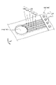
- FIG. 1 is a perspective view of a heat dissipation device according to an embodiment
- FIG. FIG. 2 is a diagram of the first member according to the embodiment viewed from the Z-axis negative direction side in the Z-axis positive direction.
- FIG. 3 is a view of the second member according to the embodiment viewed from the Z-axis positive direction side in the Z-axis negative direction.
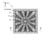
- FIG. 4 is a diagram of the intermediate member according to the embodiment viewed from the Z-axis positive direction side in the Z-axis negative direction.
- 5 is a diagram in which the first groove forming region shown in FIG. 2 and the second groove forming region shown in FIG. 3 are superimposed on the intermediate member shown in FIG. FIG.
- FIG. 6 is a diagram for explaining the flow of working fluid in the heat dissipation device according to the embodiment.
- FIG. 7 is a diagram for explaining the flow of working fluid in the heat dissipation device according to the embodiment;
- FIG. 8 is a schematic cross-sectional view showing a configuration example of a communication path.
- FIG. 9 is a schematic cross-sectional view showing another configuration example of the communication path.
- FIG. 10 is a schematic cross-sectional view showing another configuration example of the communication path.
- FIG. 11 is a schematic cross-sectional view showing another configuration example of the communication path.
- FIG. 12 is a schematic perspective view showing another configuration example of the second portion of the communication path.
- FIG. 13 is a schematic plan view showing another configuration example of individual passages.
- FIG. 14 is a schematic plan view showing another configuration example of individual passages.
- FIG. 15 is a schematic plan view showing another configuration example of individual passages.
- FIG. 16 is a schematic plan view showing another configuration example of individual passage
- a heat dissipation device that efficiently transfers heat from a high temperature part to a low temperature part by utilizing the latent heat accompanying evaporation and condensation of a working fluid (an example of a phase change substance), specifically describes the vapor chamber.
- FIG. 1 is a perspective view of a heat dissipation device according to an embodiment
- the heat dissipation device 1 has a container 2 made of ceramic.
- the container 2 has a first member 10 , a second member 20 and an intermediate member 30 .
- the first member 10 , the second member 20 , and the intermediate member 30 are all plate-shaped, and are laminated so that the intermediate member 30 is sandwiched between the first member 10 and the second member 20 .
- the container 2 has an actuation area 100 and a frame area 200 .
- the operating region 100 has an internal space, and the internal space is filled with working fluid as a phase change substance.
- working fluid such as water, hydrocarbon-based compounds, organic liquids (such as ethanol and methanol, etc.), and ammonia can be used as working liquids, for example.
- a frame area 200 is an area surrounding the operating area 100 .
- the frame region 200 is a region of the heat dissipation device 1 outside the operating region 100 .
- the active region 100 is generally hollow, while the frame region 200 is generally solid.
- the frame region 200 may, for example, leak the working fluid or the vapor of the working fluid from the interface between the first member 10 and the intermediate member 30 or the interface between the second member 20 and the intermediate member 30, or the external atmosphere may
- This area is purposely formed to be wide in order to prevent the interface from entering the internal space of the operating area 100 (that is, to ensure airtightness).
- the container 2 has a plurality of (here, two) communication paths 14 and 15 that communicate the internal space of the operating area 100 with the outside.
- the communication path 14 is used as a hydraulic fluid injection hole
- the communication path 15 is used as a gas discharge hole.
- the working fluid is injected into the internal space of the operating region 100 from the communicating path 14, and accordingly the gas present in the internal space of the operating region 100 is discharged from the communicating path 15 to the outside. be done.
- the communicating path 14 is positioned near one of the four corners of the first member 10
- the communicating path 15 is positioned near a corner positioned diagonally to the communicating path 14 .
- the heat dissipation device 1 does not necessarily need to have a plurality of communication paths 14 and 15.
- the heat dissipation device 1 may be configured to have only one of the communication paths 14 and 15 .
- the communicating passage 14 and the communicating passage 15 are closed by the sealing portion 5 .
- a resin member, a metal member, a glass member, a ceramic member, or the like can be used as the sealing portion 5 .
- the sealing portion 5 may be flush with the upper surface of the first member 10 or may protrude from the upper surface of the first member 10 .
- a heli-sert may be used as part of the sealing portion 5 .
- the working fluid is filled, for example, at a rate of 10% by volume or more and 95% by volume or less with respect to the total volume of the internal space of the operation area 100 .
- the ratio is 30% by volume or more and 75% by volume or less. More preferably, the ratio is 40% by volume or more and 65% by volume or less.
- the rest of the internal space of the operating region 100 other than the working fluid is in a vacuum state partially containing the vaporized working fluid. As a result, the vapor-liquid equilibrium can be maintained even in a high-temperature environment, so dryout is unlikely to occur, and heat diffusion is efficient even in a low-temperature environment, so thermal diffusivity can be increased in various temperature ranges. .
- the first member 10, the second member 20 and the intermediate member 30 are made of ceramic.
- Ceramics constituting first member 10, second member 20, and intermediate member 30 include, for example, alumina ( Al2O3 ), zirconia ( ZrO2), silicon carbide ( SiC), and silicon nitride ( Si3N4 ). , aluminum nitride (AlN), cordierite (Mg 2 Al 3 (AlSi 5 O 18 )), silicon impregnated silicon carbide (SiSiC), etc. may be used.
- the ceramic constituting the first member 10, the second member 20 and the intermediate member 30 may be a single crystal.
- metal heat dissipation devices Due to the material and construction method, metal heat dissipation devices are difficult to obtain rigidity, making it difficult to make them thinner. In addition, metal heat dissipation devices have room for improvement in terms of corrosion resistance, because the portion that comes into contact with the working fluid is metal.
- the heat dissipation device 1 according to the embodiment since the first member 10, the second member 20 and the intermediate member 30 are all made of ceramic, it is easier to make the heat dissipation device thinner than the heat dissipation device made of metal. It is also highly corrosive.
- the heat dissipation device 1 is installed with the first member 10 facing upward, but the orientation of the heat dissipation device 1 is not limited to the example in FIG.
- the heat dissipation device 1 may be installed with the first member 10 facing downward.
- the heat dissipation device 1 may be placed not only horizontally as shown in FIG. 1 but also vertically.
- a communicating passage for injecting hydraulic fluid is provided in the operating area.
- the working area has a reduced ceramic thickness corresponding to the inner space.
- the Weber chamber described in Patent Document 1 in which the communicating path is provided in the operating region, tends to lack durability against stress, and the container may crack or the like.
- the container if the container is cracked, the working fluid enclosed in the internal space may dry out, resulting in deterioration of the heat radiation efficiency.
- the communication paths 14 and 15 are located in the frame area 200.
- Frame region 200 is solid, unlike active region 100 .
- the durability can be improved compared to the case where the communication paths 14 and 15 are located in the operation area 100 .
- durability can be improved.
- the heat dissipation device 1 compared to the case where the communication paths 14 and 15 are located in the operation area 100, it is possible to secure a wider effective space in the operation area 100, thereby improving heat dissipation characteristics. can be made
- the frame area 200 where the communication paths 14 and 15 are located is made of the same ceramic material as the operating area 100, stress due to the difference in thermal expansion is less likely to occur. Therefore, the heat dissipation device 1 according to the embodiment has high reliability.
- FIG. 2 is a diagram of the first member 10 according to the embodiment viewed from the Z-axis negative direction side in the Z-axis positive direction.
- FIG. 2 shows the lower surface of the first member 10, specifically, the surface (third surface) facing the upper surface (first surface) of the intermediate member 30.
- FIG. 2 shows the first member 10 has grid-like first grooves 11 on the third surface.
- the first groove portion 11 has a first concave portion 11a recessed with respect to the third surface and a plurality of first convex portions 11b located within the first concave portion 11a.
- the first recessed portion 11a is located in the center of the third surface, and has, for example, a quadrangular contour in plan view.
- the plurality of first protrusions 11b are arranged in the vertical direction and the horizontal direction at intervals in the first recess 11a.
- the first recesses 11a and the plurality of first protrusions 11b form a lattice shape for the first grooves 11. As shown in FIG.
- first groove forming region 110 forms part of the operating area 100 .
- the first member 10 also has a rectangular frame-shaped first frame region 210 surrounding the first groove forming region 110 .
- the first frame area 210 forms part of the frame area 200 .
- a plurality of (here, two) through-holes 141 a and 151 a that penetrate the first member 10 in the thickness direction (here, the Z-axis direction) are located in the first frame region 210 .
- the through hole 141 a constitutes part of the first portion 141 in the communication path 14
- the through hole 151 a constitutes part of the first portion 151 in the communication path 15 .
- a heat source is arranged in the center of the upper surface (fifth surface) located on the opposite side of the lower surface (third surface) of the first member 10 .
- FIG. 3 is a view of the second member 20 according to the embodiment viewed from the Z-axis positive direction side in the Z-axis negative direction.
- FIG. 3 shows the upper surface of the second member 20 , specifically, the surface (fourth surface) facing the lower surface (second surface) of the intermediate member 30 .
- the second member 20 has a grid-like second groove portion 21 on the fourth surface.
- the second groove portion 21 has a second concave portion 21a recessed with respect to the fourth surface and a plurality of second convex portions 21b positioned within the second concave portion 21a.
- the second recessed portion 21a is located in the central portion of the fourth surface and has, for example, a quadrangular contour in plan view.
- the plurality of second protrusions 21b are arranged in the vertical direction and the horizontal direction at intervals in the second recesses 21a.
- the second recesses 21a and the plurality of second protrusions 21b form a lattice shape for the second grooves 21. As shown in FIG.
- second groove formation region 120 forms part of the operating area 100 .
- the second member 20 also has a rectangular frame-shaped second frame region 220 surrounding the second groove forming region 120 .
- the second frame region 220 constitutes part of the frame region 200 .
- the size of the second groove forming region 120 in the second member 20 is the same as the size of the first groove forming region 110 in the first member 10 . Also, the position of the second groove formation region 120 on the fourth surface of the second member 20 is the same as the position of the first groove formation region 110 on the third surface of the first member 10 .
- the working fluid can be efficiently circulated in the internal space of the heat dissipation device 1 .
- the shapes of the first groove portion 11 and the second groove portion 21 do not necessarily have to be lattice-like.
- a plurality of (here, two) recesses 141b and 151b recessed with respect to the upper surface (fourth surface) of the second member 20 are located.
- the recess 141 b forms part of the first portion 141 in the communication path 14
- the recess 151 b forms part of the first portion 151 in the communication path 15 .
- the grooves 142b and 152b are located in the second frame region 220.
- the groove portion 142b is a passage extending in a second direction (here, the Y-axis direction) that intersects with the extending direction (the first direction, here, the Z-axis direction) of the first portion 141 in the communication passage 14.
- One end opens into the recess 141 b in the first portion 141 , and the other end opens into the second groove formation region 120 .
- the groove portion 152b is a passage extending in a second direction (here, the Y-axis direction) that intersects with the extending direction (the first direction, here, the Z-axis direction) of the first portion 151 in the communicating passage 15.
- One end opens into the recess 151 b in the first portion 151 , and the other end opens into the second groove formation region 120 .
- FIG. 4 is a diagram of the intermediate member 30 according to the embodiment viewed from the Z-axis positive direction side in the Z-axis negative direction.
- the intermediate member 30 has a rectangular frame-shaped third frame region 230 .
- the third frame region 230 constitutes part of the frame region 200 .
- the intermediate member 30 is positioned between the central portion 32, which is circular in plan view and positioned inside the third frame region 230, and the central portion 32 and the third frame region 230, and is located between the central portion 32 and the third frame region 230.
- 230 and a plurality of connecting portions 33 that connect the 230 .
- the central portion 32 is located in the middle of the intermediate member 30 .
- the plurality of connecting portions 33 are spaced apart from each other and extend radially from the central portion 32 toward the third frame region 230 while widening.
- the intermediate member 30 further has multiple steam holes 36 and multiple circulation holes 37 . Both the plurality of steam holes 36 and the plurality of circulation holes 37 penetrate through the upper surface (first surface) and the lower surface (second surface) of the intermediate member 30 .
- the plurality of steam holes 36 function as part of the working fluid steam flow path.
- a plurality of steam holes 36 are positioned between two adjacent connection portions 33 . That is, the plurality of steam holes 36 and the plurality of connection portions 33 are alternately positioned in the circumferential direction. Similar to the plurality of connecting portions 33 , the plurality of steam holes 36 are spaced from each other and extend radially from the central portion 32 toward the third frame region 230 while widening.
- the plurality of circulation holes 37 function as part of the hydraulic fluid flow path.
- the circulation holes 37 are fine holes having a smaller opening area than the steam holes 36 described above.
- the return holes 37 are small enough to cause capillary action in the working fluid passing through the return holes 37 .
- a plurality of (here, two) through-holes 141c and 151c are positioned in the third frame region 230, penetrating through the intermediate member 30 in the thickness direction (here, the Z-axis direction).
- the through-hole 141 c constitutes a part of the first portion 141 in the communication path 14
- the through-hole 151 c constitutes a part of the first portion 151 in the communication path 15 .
- FIG. 5 is a diagram in which the first groove forming region 110 shown in FIG. 2 and the second groove forming region 120 shown in FIG. 3 are superimposed on the intermediate member 30 shown in FIG. 5, the communication paths 14 and 15 are omitted for easy understanding.
- the first groove formation area 110 and the second groove formation area 120 overlap the third frame area 230 of the intermediate member 30 .
- the first groove forming region 110 and the second groove forming region 120 are located closer to each other than the region in which the plurality of steam holes 36 and the plurality of return holes 37 are formed in the intermediate member 30 (hereinafter referred to as "hole forming region"). also extends outward.
- the first groove forming region 110 of the first member 10 and the second groove forming region 120 of the second member 20 are wider than the hole forming region of the intermediate member 30.
- the internal space of the heat dissipation device 1 can be widened outward compared to the case where the two-groove formation region 120 is set to the same extent as the hole formation region.
- the heat source is arranged in the central part of the heat dissipation device 1. For this reason, the temperature of the heat dissipation device 1 becomes lower the further away it is from the heat source, that is, the closer it is to the outer periphery of the heat dissipation device 1 . Also, the vapor of the working fluid condenses into a liquid as it moves to the low temperature region. Therefore, by widening the internal space of the heat dissipation device 1 outward, the working fluid is more likely to condense. For this reason, dryout can be made difficult to occur.
- the intermediate member 30 is not limited to this.
- the hole forming region may extend outward from the first groove forming region 110 and the second groove forming region 120 .
- the operating region 100 of the heat dissipation device 1 has an internal space sandwiched between the first groove forming region 110 and the second groove forming region 120, and the internal space is filled with working fluid.
- an intermediate member 30 is interposed between the first groove forming region 110 and the second groove forming region 120 in the internal space, so that the operating region 100 is located between the first groove forming region 110 and the intermediate member. It is partitioned into a first space sandwiched by the member 30 and a second space sandwiched by the second groove forming region 120 and the intermediate member 30 . These first space and second space are connected by steam holes 36 and circulation holes 37 formed in the intermediate member 30 .
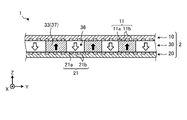
- FIG. 6 and 7 are diagrams for explaining the flow of working fluid in the heat dissipation device 1 according to the embodiment.
- 6 is a diagram in which the third frame region 230 is omitted from the diagram shown in FIG. 5
- FIG. 7 is a sectional view taken along line VII-VII in FIG. 6 and 7, white arrows indicate the flow of vapor, and black arrows indicate the flow of liquid.
- the working fluid When the working fluid is heated by a heat source, it evaporates into steam.
- the heat source is arranged in the central portion of the upper surface (fifth surface) of the first member 10 (see FIGS. 1 and 2). Therefore, the vapor of the working fluid is generated in the central portion of the first space (the space sandwiched between the first member 10 and the intermediate member 30).
- the vapor of the working fluid passes through the first groove portion 11 of the first groove forming region 110 and diffuses in the in-plane direction (XY plane direction) of the heat dissipation device 1 (see the white arrows shown in FIG. It moves to the second space (the space sandwiched between the second member 20 and the intermediate member 30) through the steam hole 36 (see white arrows shown in FIG. 7).
- the vapor that has moved to the second space condenses and becomes liquid due to the drop in temperature.
- the liquefied working fluid moves through the second groove forming region 120 toward the central portion of the heat dissipation device 1 due to the capillary force of the second groove portion 21 (see the black arrow shown in FIG. 6).
- the working fluid enters the return hole 37 and is returned to the first space by the capillary force of the return hole 37 (see black arrows shown in FIG. 7).
- the heat dissipation device 1 can transfer heat from the heat source.
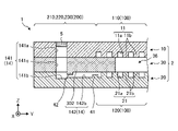
- FIG. 8 is a schematic cross-sectional view showing a configuration example of the communication path 14. As shown in FIG. Although FIG. 8 shows the communication path 14 as an example, the communication path 15 also has the same configuration as the communication path 14 .
- the communication path 14 communicates the internal space of the operating area 100 with the outside.
- the communication path 14 includes a first portion 141 extending in the thickness direction of the container 2 (here, the Z-axis direction) and opening to the outside, and a first portion 141 extending in the plane direction of the container 2 (here, the Y-axis direction). and a second portion 142 opening into the inner space of the operating region 100 .
- the first portion 141 is formed by the through hole 141 a of the first member 10 , the recess 141 b of the second member 20 and the through hole 141 c of the intermediate member 30 .
- the second portion 142 is formed by the groove portion 142 b of the second member 20 and the lower surface 302 (second surface) of the intermediate member 30 .
- FIG. 8 shows an example in which the recessed portion 141b of the communicating passage 14 is recessed more than the groove portion 142b of the second portion 142, the recessed portion 141b and the groove portion 142b may be flush with each other.
- the communication path 14 includes a first portion 141 extending in the first direction (here, the Z-axis direction) and a first portion 141 extending in a direction intersecting the first direction (here, the Y-axis direction). It has two parts 142 . In other words, the communication path 14 is curved. Therefore, according to the heat dissipation device 1 according to the embodiment, even when a high pressure is generated in the operation region 100, the sealing portion 5 is unlikely to be subjected to a high pressure, so that the reliability is high.
- the width of the first portion 141 (The width along the direction of the Z-axis) is D1
- the passage width of the second portion 142 (the width along the Z-axis direction) is D2.
- passage width D2 of second portion 142 is smaller than passage width D1 of first portion 141 .
- the passage cross-sectional area of the second portion 142 is smaller than the passage cross-sectional area of the first portion 141 .
- the first part 141 is open on the upper surface of the first member 10 and extends across the first space and the second space of the operating region 100 in the frame region 200 .
- the second part 142 is located on the second space side of the operation area 100 in the frame area 200 .
- the first space side of the first space and the second space has a high pressure.
- the pressure on the second space side of the first space and the second space is relatively low. Therefore, since the second part 142 is located on the second space side, it is possible to suppress the application of high pressure to the communication path 14 .
- the communication path 14 and the communication path 15 are positioned so as to sandwich an operating region 100 therebetween.
- the two communication paths 14 and 15 it is possible to suppress local deterioration in durability compared to, for example, the case where the two communication paths 14 and 15 are arranged side by side. can.
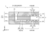
- FIG. 9 to 11 are schematic cross-sectional views showing other configuration examples of the communication path 14.
- FIG. 11 the sealing portion 5 is omitted for easy understanding.
- the second part 142 has a projecting portion 41 that projects from the bottom surface of the groove portion 142b, that is, the upper surface (fourth surface) of the second member 20 toward the lower surface (second surface) of the intermediate member 30. You may have Also, the second part 142 may have a protrusion 42 that protrudes from the lower surface 302 (second surface) of the intermediate member 30 toward the bottom surface of the groove 142b.
- the passage width D2 (see FIG. 8) of the second portion 142 is partially narrowed.
- the second portion 142 by providing the second portion 142 with a projecting portion 41 projecting from the bottom portion of the groove portion 142b and a projecting portion 42 projecting from the lower surface (second surface) of the intermediate member 30 to form a labyrinth in the second portion 142, Intrusion of hydraulic fluid into the communication path 14 can be further suppressed.
- the projecting portion 41 is positioned at the end on the operation region 100 side among both ends of the second portion 142, and the projecting portion is located at the end on the first portion 141 side among both ends of the second portion 142.
- An example is shown where 42 is located.
- the protrusion 41 is positioned at the end on the first portion 141 side among both ends of the second portion 142
- the protrusion 42 is positioned at the end on the operation region 100 side among both ends of the second portion 142 . may be located.
- the first portion 141 may have a tapered shape in which the passage width gradually narrows from the opening to the outside toward the depth direction of the container 2 .
- the first portion 141 may have a passage cross-sectional area at the end connected to the second portion 142 larger than the passage cross-sectional area at the open end opening to the outside. In this way, by narrowing the first portion 141 toward the second portion 142 side, it is possible to further suppress the hydraulic fluid from entering the communication passage 14 from the operating region 100 . Moreover, even if the working fluid enters the communicating passage 14 . By narrowing the first portion 141 , the working fluid that has entered the communicating passage 14 can be easily returned to the operating region 100 by capillary force.
- a stepped portion 43 extending outward in the radial direction of the first portion 141 may be provided at the open end portion that opens to the outside.
- the space in the communication path 14 becomes wider, so that the pressure applied to the communication path 14 can be relieved.
- the contact area with the sealing portion 5 can be increased, so that the airtightness of the operating region 100 can be improved.
- the step portion 43 it becomes easy to use, for example, a helisert as the sealing portion 5. As shown in FIG. In addition, when a helisert is used as the sealing portion 5, for example, the heat dissipation device 1 and other members can be easily connected.
- FIG. 12 is a schematic perspective view showing another configuration example of the second portion 142 in the communication passage 14. As shown in FIG. Specifically, FIG. 12 shows an enlarged portion of the upper surface (fourth surface) of the second member 20 around the second portion 142 .
- the second portion 142 has a plurality of (here, five) individual passages 142a to 142e.
- a plurality of individual passages 142a-142e connect the first portion 141 and the operating region 100, respectively. That is, each of the individual passages 142a to 142e opens into the recessed portion 141b of the first portion 141 at one end and opens into the second groove forming region 120 at the other end.
- each of the individual passages 142a to 142e is smaller than the passage cross-sectional area of the first portion 141.
- each of the individual passages 142a to 142e has a width of 150 ⁇ m or more and 400 ⁇ m or less, and a height of 100 ⁇ m or more and 1000 ⁇ m or less.
- the second portion 142 of the communication passage 14 is divided into a plurality of individual passages 142a to 142e each having a small passage cross-sectional area.
- the capillary force can work more easily than when the second portion 142 is configured by a single passage. Therefore, the injection of the working fluid into the operating region 100 can be performed more smoothly, for example, in the manufacturing process of the heat dissipation device 1 .
- the high pressure in the operating region 100 can be made less likely to be applied to the communication passage 14 and the sealing portion 5 .
- Each of the individual passages 142a-142e extends linearly from the first portion 141 toward the operating region 100.
- the second convex portion 21b of the second groove portion 21 is not positioned on the extension line of each of the individual passages 142a to 142e.
- each of the individual passages 142a to 142e is provided at a position passing between two adjacent second projections 21b when each of the individual passages 142a to 142e is extended toward the operating region 100. As shown in FIG.
- the individual passages 142a to 142e By providing the individual passages 142a to 142e at such positions, the flow of hydraulic fluid from the communication passage 14 to the operating region 100 can be prevented from being hindered by the second protrusions 21b.
- FIG. 13 shows an example in which the second convex portion 21b is not positioned on the extension line of all the individual passages 142a to 142e, but the second protrusion 21b is not positioned on the extension line of at least one of the individual passages 142a to 142e. 2 convex part 21b should not be located.
- 13 to 16 are schematic plan views showing other configuration examples of the individual passages 142a to 142e.
- the individual passages 142a to 142e extend in the second direction (Y direction) while meandering in the plane (XY plane) of the upper surface (second surface) of the second member 20. good. With such a configuration, the flow resistance of the individual passages 142a to 142e can be increased. Therefore, it is possible to further suppress the hydraulic fluid in the operating region 100 from entering the communication passage 14 .
- the individual passages 142a-142e may approach each other as they move from the first portion 141 toward the active area 100. Also, as shown in FIG. 15, the individual passages 142a-142e may separate from each other as they move from the first portion 141 toward the active region 100. As shown in FIG. 14, the individual passages 142a-142e may approach each other as they move from the first portion 141 toward the active area 100. Also, as shown in FIG. 15, the individual passages 142a-142e may separate from each other as they move from the first portion 141 toward the active region 100. As shown in FIG.
- the plurality of individual passages 142a-142e do not necessarily need to extend in the same direction.
- the hydraulic fluid flowing into the operating area 100 from each of the individual passages 142a to 142e is prevented from colliding with the second convex portion 21b located in the operating area 100 as much as possible. It is possible to obtain the communication passage 14 in which the flow direction of the hydraulic fluid is adjusted so as not to cause the hydraulic fluid to flow.
- the individual passages 142a to 142e may have a tapered shape in which the passage cross-sectional area decreases from the first portion 141 toward the operating region 100. As shown in FIG. With such a configuration, the capillary force gradually increases from the first portion 141 toward the working area 100 , so that the hydraulic fluid flows more easily from the first portion 141 into the working area 100 . Conversely, it is possible to further suppress the hydraulic fluid from entering the communication passage 14 from the operating region 100 .
- raw materials for the first member 10, the second member 20, and the intermediate member 30 are used to form green sheets by a doctor blade method, a roll compaction method, or the like, and a laminate is obtained by laminating a plurality of green sheets.
- molded bodies of the first member 10, the second member 20 and the intermediate member 30 are obtained.
- a molded body of the first member 10 in which the through holes 141a and 151a and the first groove forming region 110 are formed is obtained.
- a compact of the second member 20 in which the concave portions 141b and 151b, the groove portions 142b and 152b and the second groove forming regions 120 are formed is obtained.
- the molded bodies of the first member 10, the second member 20 and the intermediate member 30 are laminated in the order of the second member 20, the intermediate member 30 and the first member 10, and fired to obtain the first member 10.
- a sintered body of the container 2 in which the second member 20 and the intermediate member 30 are integrated is obtained.
- the first member 10, the second member 20 and the intermediate member 30 are integrally molded. Therefore, since an adhesive or the like is not required, a highly reliable heat dissipation device 1 can be obtained.
- each molded body of the first member 10, the second member 20, and the intermediate member 30 is not limited to the method described above.
- the green sheets are processed and then laminated. You may obtain each molded object.
- the formed bodies of the first member 10, the second member 20, and the intermediate member 30 are separately produced, and then laminated to obtain the formed body of the container 2.
- the molded body of the container 2 may be obtained by sequentially laminating the processed green sheets.
- the working fluid is injected into the sintered body from one of the communication paths 14 and 15, for example.
- the gas present inside the sintered body is discharged outside from the other of the communication passages 14 and 15 as the working fluid is injected.
- the inside of the sintered body is evacuated through the communicating passages 14 and 15 using a decompression device such as a vacuum pump. Although it is desirable that the inside of the sintered body be in a vacuum state, it is not strictly necessary to be in a vacuum state.
- the communicating passages 14 and 15 are sealed while the inside of the sintered body is evacuated. As a result, the communication paths 14 and 15 are sealed with the sealing portion 5, and the heat dissipation device 1 is obtained.
- the thermal device according to the embodiment is a thermal device that utilizes the latent heat of a phase-transformed material (working fluid as an example) and is made of a ceramic container (as an example , container 2) and a sealing portion (for example, a sealing portion 5).
- the container includes a phase transformation region (operation region 100 as an example) in which a phase transformation substance is enclosed, a frame region (frame region 200 as an example) surrounding the phase transformation region, and a communication passage that communicates the phase transformation region with the outside. (as an example, communication paths 14 and 15).
- the sealing portion closes the communication path.
- the communication path is located in the frame area.
- thermal device According to the thermal device according to the embodiment, durability can be improved.
- the thermal device according to the present disclosure is not limited to a heat dissipation device.
- the thermal device according to the present disclosure may be a thermal storage device that stores latent heat associated with phase transformation of a thermal storage material (an example of a phase transformation substance) as thermal energy.
- a thermal storage material an example of a phase transformation substance
- the heat storage material that undergoes a solid-liquid phase transformation or a material that undergoes a solid-solid phase transformation is used.
- the phase change substance does not necessarily need to undergo gas-liquid phase transformation.
- the phase change material need not necessarily be liquid, but may be solid.
Landscapes
- Engineering & Computer Science (AREA)
- Physics & Mathematics (AREA)
- Thermal Sciences (AREA)
- Mechanical Engineering (AREA)
- General Engineering & Computer Science (AREA)
- Life Sciences & Earth Sciences (AREA)
- Sustainable Development (AREA)
- Microelectronics & Electronic Packaging (AREA)
- Ceramic Engineering (AREA)
- Cooling Or The Like Of Electrical Apparatus (AREA)
- Cooling Or The Like Of Semiconductors Or Solid State Devices (AREA)
Priority Applications (5)
| Application Number | Priority Date | Filing Date | Title |
|---|---|---|---|
| US18/279,010 US12595974B2 (en) | 2021-02-26 | 2022-02-17 | Ceramic thermal device with three-layer vapor chamber |
| JP2023502338A JP7635359B2 (ja) | 2021-02-26 | 2022-02-17 | 熱デバイス |
| CN202280016718.2A CN116940796A (zh) | 2021-02-26 | 2022-02-17 | 热器件 |
| EP22759489.2A EP4300572A4 (en) | 2021-02-26 | 2022-02-17 | Thermal device |
| KR1020237028742A KR20230136170A (ko) | 2021-02-26 | 2022-02-17 | 열 디바이스 |
Applications Claiming Priority (2)
| Application Number | Priority Date | Filing Date | Title |
|---|---|---|---|
| JP2021-030210 | 2021-02-26 | ||
| JP2021030210 | 2021-02-26 |
Publications (1)
| Publication Number | Publication Date |
|---|---|
| WO2022181453A1 true WO2022181453A1 (ja) | 2022-09-01 |
Family
ID=83048925
Family Applications (1)
| Application Number | Title | Priority Date | Filing Date |
|---|---|---|---|
| PCT/JP2022/006476 Ceased WO2022181453A1 (ja) | 2021-02-26 | 2022-02-17 | 熱デバイス |
Country Status (6)
| Country | Link |
|---|---|
| US (1) | US12595974B2 (https=) |
| EP (1) | EP4300572A4 (https=) |
| JP (1) | JP7635359B2 (https=) |
| KR (1) | KR20230136170A (https=) |
| CN (1) | CN116940796A (https=) |
| WO (1) | WO2022181453A1 (https=) |
Families Citing this family (1)
| Publication number | Priority date | Publication date | Assignee | Title |
|---|---|---|---|---|
| CN114608368A (zh) * | 2020-12-08 | 2022-06-10 | 绍兴三花新能源汽车部件有限公司 | 换热器 |
Citations (6)
| Publication number | Priority date | Publication date | Assignee | Title |
|---|---|---|---|---|
| JPS53106961A (en) * | 1977-02-28 | 1978-09-18 | Ngk Spark Plug Co Ltd | Ceramic heating pipes and manufacturing method |
| JPS5442973A (en) | 1973-12-26 | 1979-04-05 | Burroughs Corp | Display panel |
| JPH01285791A (ja) * | 1988-05-11 | 1989-11-16 | Fujikura Ltd | 高温用セラミックヒートパイプ |
| JP2002081874A (ja) * | 2000-09-11 | 2002-03-22 | Canon Inc | プレート型ヒートパイプ及びその製造方法 |
| JP4035155B1 (ja) * | 2006-07-28 | 2008-01-16 | 株式会社渕上ミクロ | ヒートパイプ及びその製造方法 |
| WO2018139568A1 (ja) * | 2017-01-27 | 2018-08-02 | 古河電気工業株式会社 | ベーパーチャンバ |
Family Cites Families (17)
| Publication number | Priority date | Publication date | Assignee | Title |
|---|---|---|---|---|
| US2782010A (en) * | 1948-12-18 | 1957-02-19 | Modine Mfg Co | Heat exchanger |
| JPS5732613Y2 (https=) | 1976-12-31 | 1982-07-17 | ||
| JPS5810370Y2 (ja) | 1977-08-26 | 1983-02-25 | 日本特殊陶業株式会社 | 電子回路装置塔載用セラミック基板 |
| US20020192531A1 (en) * | 1998-12-30 | 2002-12-19 | Joerg Zimmerman | Liquid reactant flow field plates for liquid feed fuel cells |
| US7414843B2 (en) * | 2004-03-10 | 2008-08-19 | Intel Corporation | Method and apparatus for a layered thermal management arrangement |
| WO2007029359A1 (en) * | 2005-09-01 | 2007-03-15 | Fuchigami Micro Co., Ltd. | Heat pipe and method for manufacturing same |
| JP2009024933A (ja) * | 2007-07-19 | 2009-02-05 | Sony Corp | 熱拡散装置及びその製造方法 |
| US20090178784A1 (en) * | 2008-01-15 | 2009-07-16 | Chin-Wen Wang | Manufacturing Method of Isothermal Vapor Chamber And Product Thereof |
| JP4683080B2 (ja) | 2008-07-10 | 2011-05-11 | ソニー株式会社 | 熱輸送デバイス、電子機器、封入装置及び熱輸送デバイスの製造方法 |
| JP2010243077A (ja) * | 2009-04-07 | 2010-10-28 | Sony Corp | 熱輸送デバイスの製造方法、熱輸送デバイス、電子機器及びカシメピン |
| KR101205715B1 (ko) * | 2010-05-24 | 2012-11-28 | 한국과학기술원 | 플랫형 열 분산기 및 그 제조 방법 |
| JP2012132582A (ja) | 2010-12-20 | 2012-07-12 | Furukawa Electric Co Ltd:The | 薄型シート状ヒートパイプ |
| US20180156545A1 (en) * | 2016-12-05 | 2018-06-07 | Microsoft Technology Licensing, Llc | Vapor chamber with three-dimensional printed spanning structure |
| TWI794886B (zh) * | 2017-02-24 | 2023-03-01 | 日商大日本印刷股份有限公司 | 蒸氣腔、電子機器及蒸氣腔之製造方法 |
| TWI658248B (zh) * | 2018-02-13 | 2019-05-01 | 奇鋐科技股份有限公司 | 均溫板注水部封邊結構及其製造方法 |
| CN112902717B (zh) | 2018-05-30 | 2022-03-11 | 大日本印刷株式会社 | 蒸发室用片、蒸发室和电子设备 |
| US20240255939A1 (en) | 2023-01-27 | 2024-08-01 | Hitachi, Ltd. | Reinforcement learning system for maintenance decision making |
-
2022
- 2022-02-17 WO PCT/JP2022/006476 patent/WO2022181453A1/ja not_active Ceased
- 2022-02-17 CN CN202280016718.2A patent/CN116940796A/zh active Pending
- 2022-02-17 JP JP2023502338A patent/JP7635359B2/ja active Active
- 2022-02-17 KR KR1020237028742A patent/KR20230136170A/ko active Pending
- 2022-02-17 US US18/279,010 patent/US12595974B2/en active Active
- 2022-02-17 EP EP22759489.2A patent/EP4300572A4/en active Pending
Patent Citations (6)
| Publication number | Priority date | Publication date | Assignee | Title |
|---|---|---|---|---|
| JPS5442973A (en) | 1973-12-26 | 1979-04-05 | Burroughs Corp | Display panel |
| JPS53106961A (en) * | 1977-02-28 | 1978-09-18 | Ngk Spark Plug Co Ltd | Ceramic heating pipes and manufacturing method |
| JPH01285791A (ja) * | 1988-05-11 | 1989-11-16 | Fujikura Ltd | 高温用セラミックヒートパイプ |
| JP2002081874A (ja) * | 2000-09-11 | 2002-03-22 | Canon Inc | プレート型ヒートパイプ及びその製造方法 |
| JP4035155B1 (ja) * | 2006-07-28 | 2008-01-16 | 株式会社渕上ミクロ | ヒートパイプ及びその製造方法 |
| WO2018139568A1 (ja) * | 2017-01-27 | 2018-08-02 | 古河電気工業株式会社 | ベーパーチャンバ |
Non-Patent Citations (1)
| Title |
|---|
| See also references of EP4300572A4 |
Also Published As
| Publication number | Publication date |
|---|---|
| EP4300572A4 (en) | 2025-01-15 |
| US12595974B2 (en) | 2026-04-07 |
| US20240142179A1 (en) | 2024-05-02 |
| CN116940796A (zh) | 2023-10-24 |
| JP7635359B2 (ja) | 2025-02-25 |
| JPWO2022181453A1 (https=) | 2022-09-01 |
| KR20230136170A (ko) | 2023-09-26 |
| EP4300572A1 (en) | 2024-01-03 |
Similar Documents
| Publication | Publication Date | Title |
|---|---|---|
| JP7451678B2 (ja) | 放熱部材 | |
| JP7791301B2 (ja) | 熱デバイス | |
| TWI812723B (zh) | 蒸氣腔、電子機器及蒸氣腔用片材 | |
| JPWO2017195254A1 (ja) | ループヒートパイプ及びその製造方法並びに電子機器 | |
| WO2022181453A1 (ja) | 熱デバイス | |
| WO2019062311A1 (zh) | 用于电路板的散热件以及应用该散热件的显示面板 | |
| WO2022181566A1 (ja) | 熱デバイス | |
| EP4446684A1 (en) | Vapor chamber device | |
| CN107801358B (zh) | 散热单元的直通结构 | |
| US20250354759A1 (en) | Thermal device | |
| WO2026048992A1 (ja) | 熱デバイス | |
| WO2025197761A1 (ja) | 熱デバイス | |
| TWM556466U (zh) | 散熱單元之直通結構 | |
| TWI642892B (zh) | 散熱單元之直通結構 | |
| CN207491438U (zh) | 散热单元的直通结构 | |
| JP2023118134A (ja) | 熱伝導部材 |
Legal Events
| Date | Code | Title | Description |
|---|---|---|---|
| 121 | Ep: the epo has been informed by wipo that ep was designated in this application |
Ref document number: 22759489 Country of ref document: EP Kind code of ref document: A1 |
|
| WWE | Wipo information: entry into national phase |
Ref document number: 202280016718.2 Country of ref document: CN Ref document number: 2023502338 Country of ref document: JP |
|
| ENP | Entry into the national phase |
Ref document number: 20237028742 Country of ref document: KR Kind code of ref document: A |
|
| WWE | Wipo information: entry into national phase |
Ref document number: 1020237028742 Country of ref document: KR |
|
| WWE | Wipo information: entry into national phase |
Ref document number: 18279010 Country of ref document: US |
|
| WWE | Wipo information: entry into national phase |
Ref document number: 2022759489 Country of ref document: EP |
|
| NENP | Non-entry into the national phase |
Ref country code: DE |
|
| ENP | Entry into the national phase |
Ref document number: 2022759489 Country of ref document: EP Effective date: 20230926 |
|
| WWG | Wipo information: grant in national office |
Ref document number: 18279010 Country of ref document: US |