WO2022168994A1 - 二次電池 - Google Patents
二次電池 Download PDFInfo
- Publication number
- WO2022168994A1 WO2022168994A1 PCT/JP2022/005527 JP2022005527W WO2022168994A1 WO 2022168994 A1 WO2022168994 A1 WO 2022168994A1 JP 2022005527 W JP2022005527 W JP 2022005527W WO 2022168994 A1 WO2022168994 A1 WO 2022168994A1
- Authority
- WO
- WIPO (PCT)
- Prior art keywords
- electrode
- coating
- active material
- electrode active
- positive electrode
- Prior art date
- Legal status (The legal status is an assumption and is not a legal conclusion. Google has not performed a legal analysis and makes no representation as to the accuracy of the status listed.)
- Ceased
Links
Images


Classifications
-
- H—ELECTRICITY
- H01—ELECTRIC ELEMENTS
- H01M—PROCESSES OR MEANS, e.g. BATTERIES, FOR THE DIRECT CONVERSION OF CHEMICAL ENERGY INTO ELECTRICAL ENERGY
- H01M4/00—Electrodes
- H01M4/02—Electrodes composed of, or comprising, active material
- H01M4/36—Selection of substances as active materials, active masses, active liquids
- H01M4/362—Composites
- H01M4/366—Composites as layered products
-
- H—ELECTRICITY
- H01—ELECTRIC ELEMENTS
- H01M—PROCESSES OR MEANS, e.g. BATTERIES, FOR THE DIRECT CONVERSION OF CHEMICAL ENERGY INTO ELECTRICAL ENERGY
- H01M10/00—Secondary cells; Manufacture thereof
- H01M10/05—Accumulators with non-aqueous electrolyte
- H01M10/052—Li-accumulators
-
- H—ELECTRICITY
- H01—ELECTRIC ELEMENTS
- H01M—PROCESSES OR MEANS, e.g. BATTERIES, FOR THE DIRECT CONVERSION OF CHEMICAL ENERGY INTO ELECTRICAL ENERGY
- H01M4/00—Electrodes
- H01M4/02—Electrodes composed of, or comprising, active material
- H01M4/13—Electrodes for accumulators with non-aqueous electrolyte, e.g. for lithium-accumulators; Processes of manufacture thereof
-
- H—ELECTRICITY
- H01—ELECTRIC ELEMENTS
- H01M—PROCESSES OR MEANS, e.g. BATTERIES, FOR THE DIRECT CONVERSION OF CHEMICAL ENERGY INTO ELECTRICAL ENERGY
- H01M4/00—Electrodes
- H01M4/02—Electrodes composed of, or comprising, active material
- H01M4/13—Electrodes for accumulators with non-aqueous electrolyte, e.g. for lithium-accumulators; Processes of manufacture thereof
- H01M4/131—Electrodes based on mixed oxides or hydroxides, or on mixtures of oxides or hydroxides, e.g. LiCoOx
-
- H—ELECTRICITY
- H01—ELECTRIC ELEMENTS
- H01M—PROCESSES OR MEANS, e.g. BATTERIES, FOR THE DIRECT CONVERSION OF CHEMICAL ENERGY INTO ELECTRICAL ENERGY
- H01M4/00—Electrodes
- H01M4/02—Electrodes composed of, or comprising, active material
- H01M4/13—Electrodes for accumulators with non-aqueous electrolyte, e.g. for lithium-accumulators; Processes of manufacture thereof
- H01M4/134—Electrodes based on metals, Si or alloys
-
- H—ELECTRICITY
- H01—ELECTRIC ELEMENTS
- H01M—PROCESSES OR MEANS, e.g. BATTERIES, FOR THE DIRECT CONVERSION OF CHEMICAL ENERGY INTO ELECTRICAL ENERGY
- H01M4/00—Electrodes
- H01M4/02—Electrodes composed of, or comprising, active material
- H01M4/36—Selection of substances as active materials, active masses, active liquids
-
- H—ELECTRICITY
- H01—ELECTRIC ELEMENTS
- H01M—PROCESSES OR MEANS, e.g. BATTERIES, FOR THE DIRECT CONVERSION OF CHEMICAL ENERGY INTO ELECTRICAL ENERGY
- H01M4/00—Electrodes
- H01M4/02—Electrodes composed of, or comprising, active material
- H01M4/36—Selection of substances as active materials, active masses, active liquids
- H01M4/38—Selection of substances as active materials, active masses, active liquids of elements or alloys
- H01M4/386—Silicon or alloys based on silicon
-
- H—ELECTRICITY
- H01—ELECTRIC ELEMENTS
- H01M—PROCESSES OR MEANS, e.g. BATTERIES, FOR THE DIRECT CONVERSION OF CHEMICAL ENERGY INTO ELECTRICAL ENERGY
- H01M4/00—Electrodes
- H01M4/02—Electrodes composed of, or comprising, active material
- H01M4/36—Selection of substances as active materials, active masses, active liquids
- H01M4/48—Selection of substances as active materials, active masses, active liquids of inorganic oxides or hydroxides
- H01M4/52—Selection of substances as active materials, active masses, active liquids of inorganic oxides or hydroxides of nickel, cobalt or iron
- H01M4/525—Selection of substances as active materials, active masses, active liquids of inorganic oxides or hydroxides of nickel, cobalt or iron of mixed oxides or hydroxides containing iron, cobalt or nickel for inserting or intercalating light metals, e.g. LiNiO2, LiCoO2 or LiCoOxFy
-
- H—ELECTRICITY
- H01—ELECTRIC ELEMENTS
- H01M—PROCESSES OR MEANS, e.g. BATTERIES, FOR THE DIRECT CONVERSION OF CHEMICAL ENERGY INTO ELECTRICAL ENERGY
- H01M4/00—Electrodes
- H01M4/02—Electrodes composed of, or comprising, active material
- H01M4/62—Selection of inactive substances as ingredients for active masses, e.g. binders, fillers
-
- H—ELECTRICITY
- H01—ELECTRIC ELEMENTS
- H01M—PROCESSES OR MEANS, e.g. BATTERIES, FOR THE DIRECT CONVERSION OF CHEMICAL ENERGY INTO ELECTRICAL ENERGY
- H01M4/00—Electrodes
- H01M4/02—Electrodes composed of, or comprising, active material
- H01M4/62—Selection of inactive substances as ingredients for active masses, e.g. binders, fillers
- H01M4/624—Electric conductive fillers
- H01M4/625—Carbon or graphite
-
- H—ELECTRICITY
- H01—ELECTRIC ELEMENTS
- H01M—PROCESSES OR MEANS, e.g. BATTERIES, FOR THE DIRECT CONVERSION OF CHEMICAL ENERGY INTO ELECTRICAL ENERGY
- H01M4/00—Electrodes
- H01M4/02—Electrodes composed of, or comprising, active material
- H01M2004/026—Electrodes composed of, or comprising, active material characterised by the polarity
- H01M2004/028—Positive electrodes
-
- Y—GENERAL TAGGING OF NEW TECHNOLOGICAL DEVELOPMENTS; GENERAL TAGGING OF CROSS-SECTIONAL TECHNOLOGIES SPANNING OVER SEVERAL SECTIONS OF THE IPC; TECHNICAL SUBJECTS COVERED BY FORMER USPC CROSS-REFERENCE ART COLLECTIONS [XRACs] AND DIGESTS
- Y02—TECHNOLOGIES OR APPLICATIONS FOR MITIGATION OR ADAPTATION AGAINST CLIMATE CHANGE
- Y02E—REDUCTION OF GREENHOUSE GAS [GHG] EMISSIONS, RELATED TO ENERGY GENERATION, TRANSMISSION OR DISTRIBUTION
- Y02E60/00—Enabling technologies; Technologies with a potential or indirect contribution to GHG emissions mitigation
- Y02E60/10—Energy storage using batteries
Definitions
- the present invention relates to secondary batteries. More specifically, it relates to lithium ion secondary batteries.
- Secondary batteries are so-called storage batteries, so they can be charged and discharged repeatedly, and are used for a variety of purposes. Secondary batteries are widely used, for example, in mobile devices such as mobile phones, smart phones, and laptop computers, and as battery packs in hybrid vehicles and electric vehicles.
- the inventor of the present application realized that there were problems to be overcome with conventional secondary batteries, and found the need to take measures to address them. Specifically, the inventors of the present application have found that there are the following problems.
- a secondary battery generally has a structure in which a positive electrode, a negative electrode, a separator disposed between the positive electrode and the negative electrode, and an electrolytic solution are enclosed in an outer package.
- the positive and negative electrodes contain an electrode active material, and the positive electrode contains positive electrode active material particles as the electrode active material.
- Patent Documents 1 to 6 and Non-Patent Document 1 disclose that lithium-ion secondary batteries contain particles such as lithium-transition metal composite oxides as positive electrode active materials.
- the positive electrode active material contains particles such as a lithium transition metal composite oxide, there is a risk that unreacted lithium compounds derived from raw materials may react with organic solvents (see Patent Document 1), or unreacted lithium compounds derived from such raw materials may react.
- the lithium compound may react with the electrolyte to generate gas (see Patent Document 2).
- Patent Documents 3 and 4 When such an electrode active material is mixed with a conductive agent or the like, the electrode active material particles are broken, and the fractured surfaces of the particles are exposed, which easily causes a deterioration reaction of the electrode active material and the electrolyte (Patent Documents 3 and 4). reference).
- the surface of the electrode active material particles, particularly the primary particles thereof, is coated or coated with a compound such as an oxide, but the improvement of the cycle characteristics of the secondary battery still remains. It was found that it was not sufficient and there was room for further improvement.
- the electrode in a secondary battery, usually contains an electrode active material and other electrode constituent materials other than the electrode active material, such as a conductive aid. It is thought that there is a possibility that the cycle characteristics may be deteriorated by reacting with a liquid or the like.
- the present invention has been made in view of such problems. Accordingly, it is a primary object of the present invention to provide a secondary battery with improved cycle characteristics.
- the inventors of the present application have attempted to solve the above problems by dealing with them in a new direction, rather than dealing with them on the extension of the conventional technology. As a result, the present inventors have invented a secondary battery that achieves the above-described main object.
- the inventors of the present application have found that in the electrode of a secondary battery, not only the electrode active material but also the surface of other electrode constituent materials other than the electrode active material are coated with the same coating material as the electrode active material, or The inventors have found that by covering the surface of other electrode constituent materials with a coating material, more improved cycle characteristics can be obtained.
- a secondary battery including an electrode comprising an electrode active material and an electrode constituent material other than the electrode active material, wherein at least part of the electrode active material is covered with a coating material.
- a secondary battery in which at least part of the other electrode constituent material is also covered with the coating material.
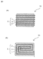
- FIG. 1 schematically shows a cross section of an electrode assembly that can be used in a secondary battery according to one embodiment of the present invention
- A planar laminated electrode assembly
- B wound electrode assembly
- . 2 is an image showing the result of mapping analysis (atomic mapping) by scanning transmission electron microscope-energy dispersive X-ray spectroscopy (STEM-EDX) in the positive electrode material layer of the positive electrode included in the coin cell produced in Example 9.
- FIG. is. 3 is an image showing the result of mapping analysis (atomic mapping) by scanning transmission electron microscope-energy dispersive X-ray spectroscopy (STEM-EDX) in the positive electrode material layer of the positive electrode included in the coin cell produced in Comparative Example 1.
- STEM-EDX scanning transmission electron microscope-energy dispersive X-ray spectroscopy
- the “cross-sectional view” described directly or indirectly in this specification means that the secondary battery (see Figure 1).
- the direction of "thickness” described directly or indirectly in this specification is based on the stacking direction of the electrode materials that make up the secondary battery.
- the direction of "thickness” corresponds to the plate thickness direction of the secondary battery.
- a “plane” as used indirectly in this specification is based on a perspective view of an object viewed from above or below along the direction of such thickness.
- the terms “vertical direction” and “horizontal direction” used directly or indirectly in this specification correspond to the vertical direction and the lateral direction in the drawings, respectively. Unless otherwise specified, the same symbols or symbols shall indicate the same parts and/or parts or the same meaning.
- the downward vertical direction that is, the direction in which gravity acts
- the opposite direction corresponds to the "upward direction”.
- a "secondary battery” as used herein refers to a battery that can be repeatedly charged and discharged. Therefore, the secondary battery according to one embodiment of the present invention is not overly bound by its name, and can include, for example, an electric storage device.
- a secondary battery according to an embodiment of the present invention comprises, for example, an electrode assembly formed by laminating electrode constituent units or electrode constituent layers each including a positive electrode, a negative electrode and a separator.
- FIGS. 1A and 1B illustrate an electrode assembly 10.
- the positive electrode 1 and the negative electrode 2 may be stacked via the separator 3 to form an electrode structural unit 5 (or an electrode unit).
- the electrode assembly 10 may be configured by stacking at least one or more such electrode structural units 5 .
- the electrode structural unit 5 has a planar laminated structure in which the electrode structural unit 5 is laminated in a planar shape without being wound.
- the electrode structural unit 5 has a wound laminated structure in which it is wound. That is, in FIG. 1B, an electrode structural unit 5 (or an electrode unit) including a positive electrode 1, a negative electrode 2, and a separator 3 disposed between the positive electrode and the negative electrode is wound into a roll. may have. Note that FIG. 1(B) merely illustrates the winding-type laminated structure of the electrode assembly, and the electrode assembly is wrapped with the cross section shown in FIG. 1(B) facing upward or downward. It can be placed inside the body.
- planar lamination type structure or winding type structure is merely an example as the structure of the electrode assembly.
- the structure of the electrode assembly is not necessarily limited to a flat laminated structure or a wound structure. It may have other structures such as an and-folding type structure.
- such an electrode assembly may be enclosed in an outer package together with an electrolyte (eg, non-aqueous electrolyte).
- an electrolyte eg, non-aqueous electrolyte
- the electrode assembly may be enclosed in the outer package together with a liquid electrolyte (eg, an electrolytic solution, which in some embodiments contains an organic solvent or the like).
- the positive electrode is composed of at least a positive electrode material layer as an electrode material layer and, if necessary, a positive electrode current collector.
- the cathode material layer contains a cathode active material as an electrode active material.
- a positive electrode current collector may or may not be present in the positive electrode.
- the positive electrode may have a positive electrode material layer on at least one side of the positive electrode current collector.
- each of the plurality of positive electrodes in the electrode assembly may be provided with a positive electrode material layer on both sides of the positive electrode current collector, or may be provided with a positive electrode material layer only on one side of the positive electrode current collector. Anything is fine.
- the positive current collector may, for example, have a foil form. More specifically, the positive electrode current collector may be made of metal foil.
- the negative electrode is composed of at least a negative electrode material layer as an electrode material layer and, if necessary, a negative electrode current collector.
- the negative electrode material layer contains a negative electrode active material as an electrode active material.
- the negative electrode may or may not have a negative electrode current collector.
- the negative electrode may be provided with a negative electrode material layer on at least one side of the negative electrode current collector.
- each of the plurality of negative electrodes in the electrode assembly may be provided with a negative electrode material layer on both sides of the negative electrode current collector, or may be provided with a negative electrode material layer only on one side of the negative electrode current collector. Anything is fine.
- the negative electrode current collector may, for example, have a foil form. More specifically, the negative electrode current collector may be made of metal foil.
- the electrode active materials that can be contained in the positive electrode material layer and the negative electrode material layer, that is, the positive electrode active material and the negative electrode active material, respectively, are substances that can directly participate in the transfer of electrons in the secondary battery, and charge and discharge, that is, charge and discharge. It is the main material of the positive and negative electrodes responsible for battery reactions such as discharge.
- ions can be brought to the electrolyte due to the "positive electrode active material that may be contained in the positive electrode material layer” and the "negative electrode active material that may be contained in the negative electrode material layer". Such ions can move between the positive electrode and the negative electrode to transfer electrons and charge and discharge.
- the positive electrode material layer and the negative electrode material layer may be layers capable of intercalating and deintercalating lithium ions. That is, the secondary battery according to one embodiment of the present invention is, for example, a non-aqueous electrolyte secondary battery in which the battery can be charged and discharged by moving lithium ions between the positive electrode and the negative electrode through the non-aqueous electrolyte. It can be
- the secondary battery according to one embodiment of the present invention can correspond to a so-called "lithium ion battery".
- a lithium ion battery has a layer in which a positive electrode and a negative electrode can intercalate and deintercalate lithium ions.
- the positive electrode active material of the positive electrode layer is made up of smaller particles of the positive electrode active material (hereinafter referred to as “primary particles”) aggregated and/or aggregated into larger particles (hereinafter referred to as “secondary particles”). ”).
- the average particle diameter of the secondary particles is not particularly limited, and may be, for example, 1 ⁇ m or more and 100 ⁇ m or less, 1 ⁇ m or more and 50 ⁇ m or less, or 3 ⁇ m or more and 30 ⁇ m or less.
- the average particle size value can be determined, for example, by a particle size distribution meter.
- Particle size can also be determined, for example, by image analysis. In such a case, the average value of the measured values of the particle size at arbitrary 10 locations may be adopted as the value of the average particle size.
- the positive electrode may contain a binder in its positive electrode material layer. Although it is only an example, when contact between particles of the positive electrode active material is involved, the positive electrode material layer may contain a binder for more sufficient contact and/or shape retention.
- the positive electrode may contain a conductive material such as a conductive aid (eg, conductive particles, preferably conductive particles having a particle shape when viewed in cross section, etc.) in the positive electrode material layer.
- a conductive aid may be included in the positive electrode material layer to facilitate the transfer of electrons that can drive battery reactions.
- the negative electrode active material of the negative electrode material layer is configured to contain larger particles (secondary particles) formed by aggregation and/or agglomeration of smaller particles (primary particles) of the negative electrode active material. good.
- the average particle diameter of such secondary particles is not particularly limited, and may be, for example, 1 ⁇ m or more and 100 ⁇ m or less, 1 ⁇ m or more and 50 ⁇ m or less, or 3 ⁇ m or more and 30 ⁇ m or less.
- the negative electrode may contain a binder in its negative electrode material layer. Although this is merely an example, when contact between particles of the negative electrode active material is involved, the negative electrode material layer may contain a binder for more sufficient contact and/or shape retention.
- the negative electrode may contain a conductive material such as a conductive aid (for example, conductive particles, preferably conductive particles having a particle shape when viewed in cross section, etc.) in the negative electrode material layer.
- a conductive aid may be included in the negative electrode material layer to facilitate the transfer of electrons that can drive the battery reaction.
- the electrode material layers such as the positive electrode material layer and the negative electrode material layer can be called “positive electrode material layer” and “negative electrode material layer”, respectively.
- the positive electrode active material may be, for example, a material that contributes to intercalation and deintercalation of lithium ions. From this point of view, the positive electrode active material may be, for example, a lithium-containing metal compound or a lithium-containing oxide (lithium-containing composite oxide, etc.). More specifically, the positive electrode active material is a lithium metal compound or lithium transition metal composite oxide containing lithium and at least one transition metal selected from the group consisting of cobalt, nickel, manganese and iron, good.
- the positive electrode material layer of the secondary battery according to one embodiment of the present invention may contain such a lithium metal compound or lithium transition metal composite oxide as a positive electrode active material.
- the positive electrode active material may be lithium cobaltate, lithium nickelate, lithium manganate, lithium iron phosphate, or a transition metal thereof partially replaced by another metal.
- Such a positive electrode active material may be contained as a single species, it may also be contained in combination of two or more species.
- the content of the positive electrode active material in the positive electrode layer is not particularly limited, and is 60% by weight or more and less than 100% by weight, 60% by weight with respect to the total weight of the positive electrode material layer (in other words, the positive electrode material layer is 100% by weight). 98% by weight or more, 70% by weight or more and 98% by weight or less, for example, 85% by weight or more and 98% by weight or less.
- the binder that can be contained in the positive electrode material layer is not particularly limited.
- the binder for the positive electrode layer is, for example, at least one selected from the group consisting of polyvinylidene fluoride, vinylidene fluoride-hexafluoropropylene copolymer, vinylidene fluoride-tetrafluoroethylene copolymer, polytetrafluoroethylene, and the like. Species can be mentioned.
- the content of the binder in the positive electrode layer is, for example, 1% by weight or more and 20% by weight or less, or 1% by weight or more and 10% by weight or less with respect to the total weight of the positive electrode material layer (in other words, the positive electrode material layer is 100% by weight). , 1 wt % to 8 wt %, 1 wt % to 5 wt %, or 1 wt % to 3 wt %, and the like.
- the conductive aid that can be contained in the positive electrode material layer is not particularly limited.
- the conductive additive for the positive electrode layer includes carbon black such as thermal black, furnace black, channel black, ketjen black and/or acetylene black, graphite such as natural graphite and/or artificial graphite, carbon nanotubes and/or Tubular and fibrous carbon such as vapor grown carbon fibers, metal powders such as copper, nickel, aluminum and/or silver, and/or conductive polymers such as polyphenylene and/or polyphenylene derivatives may be mentioned.
- the content of the conductive additive in the positive electrode layer may be, for example, 1% by weight or more with respect to the total weight of the positive electrode material layer (in other words, when the positive electrode material layer is 100% by weight). If the positive electrode material layer is 100% by weight, the content of the conductive aid in the positive electrode layer is, for example, 1% by weight or more and 20% by weight or less, 1% by weight or more and 10% by weight or less, 1% by weight or more and 8% by weight or less, or It may be 1% by weight or more and 5% by weight or less.
- the thickness of the positive electrode material layer is not particularly limited.
- the thickness dimension of the positive electrode material layer may be 1 ⁇ m or more and 300 ⁇ m or less, or may be 5 ⁇ m or more and 200 ⁇ m or less.
- the thickness dimension of the positive electrode material layer is the thickness inside the secondary battery, and the average value of the measured values at arbitrary 10 points may be adopted.
- the negative electrode active material may be a material that contributes to the absorption and release of lithium ions. From this point of view, the negative electrode active material may be, for example, various carbon materials, oxides, and/or lithium alloys, metallic lithium, and the like.
- Examples of various carbon materials for the negative electrode active material include graphite (more specifically, natural graphite and/or artificial graphite), hard carbon, soft carbon, and/or diamond-like carbon.
- graphite more specifically, natural graphite and/or artificial graphite
- hard carbon soft carbon
- diamond-like carbon diamond-like carbon.
- graphite in particular has high electron conductivity and excellent adhesion to the negative electrode current collector.
- the oxide of the negative electrode active material at least one selected from the group consisting of silicon oxide, tin oxide, indium oxide, zinc oxide and lithium oxide can be mentioned.
- Such an oxide may be amorphous as its structural form. This is because deterioration due to non-uniformity such as grain boundaries or defects is less likely to occur.
- the lithium alloy of the negative electrode active material may be an alloy of lithium and a metal capable of forming an alloy.
- Binary, ternary or higher alloys of lithium with metals such as Al, Si, Pb, Sn, In, Bi, Ag, Ba, Ca, Hg, Pd, Pt, Te, Zn and/or La can be Such alloys may, for example, be amorphous in their structural form. This is because deterioration due to non-uniformity such as grain boundaries or defects is less likely to occur.
- the content of the negative electrode active material in the negative electrode layer is not particularly limited, and is 60% by weight or more and less than 100% by weight, or 60% by weight based on the total weight of the negative electrode material layer (in other words, the negative electrode material layer is 100% by weight). 98% by weight or more, 70% by weight or more and 98% by weight or less, for example, 85% by weight or more and 98% by weight or less.
- the binder that can be contained in the negative electrode material layer is not particularly limited.
- the binder for the negative electrode layer include at least one selected from the group consisting of styrene-butadiene rubber, polyacrylic acid, polyvinylidene fluoride, polyimide-based resins, and polyamide-imide-based resins.
- the content of the binder in the negative electrode layer is, for example, 1% by weight or more and 20% by weight or less, preferably 1% by weight or more and 10% by weight, based on the total weight of the negative electrode material layer (in other words, the negative electrode material layer is 100% by weight). % or less, more preferably 1 wt % or more and 8 wt % or less, 1 wt % or more and 5 wt % or less, or 1 wt % or more and 3 wt % or less.
- the conductive aid that can be contained in the negative electrode material layer is not particularly limited.
- the conductive aid for the negative electrode layer includes carbon black such as thermal black, furnace black, channel black, ketjen black and/or acetylene black, graphite such as natural graphite and/or artificial graphite, carbon nanotubes and/or Tubular and fibrous carbon such as vapor grown carbon fibers, metal powders such as copper, nickel, aluminum and/or silver, and/or conductive polymers such as polyphenylene and/or polyphenylene derivatives may be mentioned.
- the content of the conductive aid in the negative electrode layer may be, for example, 1% by weight or more relative to the total weight of the negative electrode material layer (in other words, when the negative electrode material layer is 100% by weight). If the negative electrode material layer is 100% by weight, the content of the conductive aid in the negative electrode material layer is, for example, 1% by weight or more and 20% by weight or less, 1% by weight or more and 10% by weight or less, 1% by weight or more and 8% by weight or less, or It may be 1% by weight or more and 5% by weight or less.
- the dimensions of the negative electrode material layer are not particularly limited.
- the dimension of the negative electrode material layer may be 1 ⁇ m or more and 300 ⁇ m or less, or 5 ⁇ m or more and 200 ⁇ m or less.
- the thickness dimension of the negative electrode material layer is the thickness inside the secondary battery, and the average value of the measured values at arbitrary 10 points may be adopted.
- the positive electrode current collector and negative electrode current collector that can be used for the positive electrode and the negative electrode are members that can collect and supply electrons generated in the electrode active material due to the battery reaction.
- a current collector may be a sheet metal member and may have a perforated or perforated morphology.
- the current collector may be metal foil, perforated metal, mesh, expanded metal, and/or plate, and the like.
- the positive electrode current collector that can be used for the positive electrode may consist of a metal foil containing at least one selected from the group consisting of aluminum, stainless steel, nickel, and the like.
- the positive electrode current collector may be an aluminum foil.
- the negative electrode current collector that can be used for the negative electrode may consist of a metal foil containing at least one selected from the group consisting of copper, stainless steel, nickel, and the like.
- the negative electrode current collector may be a copper foil.
- stainless steel refers to, for example, chromium or alloy steel containing chromium and nickel, as defined in "JIS G 0203 Iron and Steel Terms".
- the thickness of the positive electrode current collector and the negative electrode current collector is not particularly limited.
- the thickness dimension of the positive electrode current collector and the negative electrode current collector may be 1 ⁇ m or more and 100 ⁇ m or less, for example, 10 ⁇ m or more and 70 ⁇ m or less.
- the thickness dimension of the positive electrode current collector and the negative electrode current collector is the thickness inside the secondary battery, and an average value of measured values at arbitrary 10 points may be adopted.
- the separator that can be used for the positive electrode and the negative electrode is a member that can be provided from the viewpoint of preventing short circuits due to contact between the positive electrode and the negative electrode and/or retaining the electrolyte.
- the separator is a member that allows ions to pass through while preventing electronic contact between the positive electrode and the negative electrode.
- the separator is a porous or microporous insulating member and may have a membrane form due to its small thickness.
- a polyolefin microporous membrane may be used as the separator.
- a microporous membrane that can be used as a separator may contain, for example, only polyethylene (PE) or only polypropylene (PP) as polyolefin.
- the separator may be a laminate that can be composed of a "PE microporous membrane” and a "PP microporous membrane”.
- the surface of the separator may be covered with an inorganic particle coat layer and/or an adhesive layer or the like. The surface of the separator may have adhesiveness.
- the thickness of the separator is not particularly limited.
- the thickness dimension of the separator may be 1 ⁇ m or more and 100 ⁇ m or less, for example, 5 ⁇ m or more and 20 ⁇ m or less.
- the thickness dimension of the separator is the thickness inside the secondary battery (particularly the thickness between the positive electrode and the negative electrode), and the average value of the measured values at arbitrary 10 points may be adopted.
- the separator should not be particularly bound by its name, and may be a solid electrolyte, gel electrolyte, and/or insulating inorganic particles that can have similar functions.
- a positive electrode layer slurry prepared by mixing a positive electrode active material, optionally a binder, and optionally a conductive aid in a dispersion medium for example, a medium such as an organic solvent
- a positive current collector for example, a positive electrode layer slurry prepared by mixing a positive electrode active material, optionally a binder, and optionally a conductive aid in a dispersion medium (for example, a medium such as an organic solvent) is used as a positive current collector. It can be obtained by applying it to the body, drying it, and then rolling the dry coating with a roll press or the like.
- a negative electrode layer slurry prepared by mixing a negative electrode active material, optionally a binder, and optionally a conductive aid in a dispersion medium for example, a medium such as an organic solvent
- an electrode assembly including an electrode constituent unit or an electrode constituent layer including a positive electrode, a negative electrode and a separator may be enclosed in an exterior body together with an electrolyte.
- the electrolyte can help transport metal ions that can be released from the electrodes (positive and/or negative).
- the electrolyte may be a "non-aqueous" electrolyte including organic electrolytes and/or organic solvents and the like.
- the electrolyte may be an "aqueous" electrolyte comprising water.
- the electrolyte may be an organic electrolyte and/or a “non-aqueous” electrolyte containing an organic solvent (hereinafter referred to as “non-aqueous electrolyte”). . That is, the electrolyte may be a non-aqueous electrolyte.
- the electrolyte there will be metal ions that can be released from the electrodes (positive and/or negative electrodes), and therefore the electrolyte can assist in the movement of metal ions in the battery reactions.
- a secondary battery according to an embodiment of the present invention may be a non-aqueous electrolyte secondary battery using a "non-aqueous” electrolyte containing a "non-aqueous” solvent and a solute as the electrolyte.
- the electrolyte may have a form such as a liquid or a gel (in the present disclosure, a "liquid” non-aqueous electrolyte can also be referred to as a "non-aqueous electrolyte liquid").
- the non-aqueous electrolyte may be an electrolyte containing a non-aqueous solvent and a solute.
- a specific solvent for the non-aqueous electrolyte may contain at least carbonate.
- Such carbonates may be cyclic carbonates and/or linear carbonates.
- cyclic carbonates include at least one selected from the group consisting of propylene carbonate (PC), ethylene carbonate (EC), butylene carbonate (BC) and vinylene carbonate (VC). be able to.
- PC propylene carbonate
- EC ethylene carbonate
- BC butylene carbonate
- VC vinylene carbonate
- chain carbonates include at least one selected from the group consisting of dimethyl carbonate (DMC), diethyl carbonate (DEC), ethylmethyl carbonate (EMC) and dipropyl carbonate (DPC).
- DMC dimethyl carbonate
- DEC diethyl carbonate
- EMC ethylmethyl carbonate
- DPC dipropyl carbonate
- a combination of cyclic carbonates and linear carbonates may be used as the solvent for the non-aqueous electrolyte.
- a mixture of ethylene carbonate (EC) and diethyl carbonate (DEC), a mixture of ethylene carbonate (EC) and ethylmethyl carbonate (EMC), and the like may be used.
- the solute of the non-aqueous electrolyte is not particularly limited, but Li salts such as LiPF 6 and/or LiBF 4 may be used.
- an electrode assembly can be composed of a positive electrode, a negative electrode, and a separator that can be arranged between the positive electrode and the negative electrode.
- the electrode assembly may have any structure in the present disclosure.
- the electrode assembly may have a laminated structure (eg, planar laminated structure), a wound structure (eg, jellyroll structure), or a stack and folded structure.
- the exterior body of the secondary battery is, for example, a member that can accommodate or wrap an electrode assembly formed by stacking electrode constituent units or electrode constituent layers that include a positive electrode, a negative electrode, and a separator.
- the exterior body is not particularly limited, and may be, for example, a flexible pouch (soft bag body) or a hard case (hard housing).
- the flexible pouch can usually be formed from a laminate film. Sealing can be achieved, for example, by heat sealing the perimeter.
- a laminate film may have a multilayer film structure in which a metal foil and a polymer film are laminated. Specifically, a three-layer structure consisting of outer layer polymer film/metal foil/inner layer polymer film is exemplified.
- the outer layer polymer film serves to prevent damage to the metal foil due to permeation of moisture and/or contact, and polymers such as polyamide and/or polyester can be preferably used.
- the metal foil serves to prevent permeation of moisture and/or gas. Foils made of copper, aluminum and/or stainless steel can be preferably used.
- the inner layer polymer film protects the metal foil from the electrolyte to be housed inside, and also contributes to melt-sealing at the time of heat sealing.
- Polyolefins such as polypropylene
- acid-modified polyolefins can be preferably used.
- the thickness of the laminate film in the flexible pouch is not particularly limited, and may be, for example, 1 ⁇ m or more and 1 mm or less.
- the hard case can usually be made of a metal plate. Sealing can be achieved, for example, by lasing the periphery.
- the metal plate may comprise metallic materials such as aluminum, nickel, iron, copper and/or stainless steel.
- the thickness of the metal plate is not particularly limited, and may be, for example, 1 ⁇ m or more and 1 mm or less.
- the exterior body may have, for example, a two-part configuration of a first exterior body and a second exterior body.
- the exterior body may be a metal exterior body made of a non-laminated metal plate.
- the basic configuration of the secondary battery described above may be changed or modified as necessary.
- the secondary battery of the present disclosure relates to a secondary battery having an electrode comprising an electrode active material and an electrode constituent material other than the electrode active material (hereinafter sometimes referred to as "electrode of the present disclosure").
- electrode of the present disclosure an electrode comprising an electrode active material and an electrode constituent material other than the electrode active material.
- the "electrode active material” corresponds to the electrode constituent material contained in the electrode material layer.
- Such an electrode active material may be a positive electrode active material or a negative electrode active material.
- the positive electrode of the electrode assembly of the secondary battery contains a positive electrode active material as its electrode constituent material (for example, the positive electrode material layer contains positive electrode active material particles).
- the negative electrode of the electrode assembly of the secondary battery contains a negative electrode active material as its electrode constituent material (for example, the negative electrode material layer contains negative electrode active material particles).
- the positive electrode active materials and negative electrode active materials the positive electrode active materials and negative electrode active materials described above can be used without particular limitations.
- the electrode active material is, as described above, a material that can be contained in an electrode of an electrode assembly of a secondary battery such as a lithium ion battery.
- the electrode assembly has a structure in which at least one electrode constituent unit or electrode constituent layer including at least a positive electrode, a negative electrode and a separator is laminated.
- the electrode assembly may be, for example, a planar laminated electrode assembly (see FIG. 1(A)) or a wound electrode assembly (see FIG. 1(B)).
- the average primary particle size of each of the positive electrode active material particles and the negative electrode active material particles is not particularly limited, and may be, for example, the same as or similar to the average primary particle size of the electrode active material particles contained in the lithium ion secondary battery.
- the average primary particle size of each of the positive electrode active material particles and the negative electrode active material particles may be, for example, 0.1 ⁇ m or more and 1 ⁇ m or less.
- an electrode constituent material other than an electrode active material means a substance or material that can be contained in an electrode (more specifically, an electrode material layer) excluding an electrode active material. (hereinafter sometimes simply referred to as “another electrode constituent material”).
- an electrode constituent material As another electrode component in the present disclosure, one or more types of substances or materials may be included in the electrode (particularly the electrode material layer).
- Another electrode constituent material is, for example, a conductive aid.
- the conductive aid corresponds to an electrode constituent material that can be included in the electrode in order to facilitate smoother transfer of electrons that can promote battery reactions.
- the conductive aid contained in the electrode material layer together with the electrode active material may react with, for example, the electrolytic solution and/or the organic solvent to generate gas, which may deteriorate the cycle characteristics.
- the inventor of the present application has found. Although not bound by a particular theory, in the present disclosure, such a conductive agent is covered with a coating material together with an electrode active material, thereby causing undesirable side reactions (particularly gas generation) in secondary batteries. It can be suppressed, and battery characteristics such as cycle characteristics can be further improved.
- the conductive aid may be contained in the electrode material layer in a plurality of forms in a cross-sectional view of the electrode material layer. Further, the conductive aid may be contained so as to form particles and/or fibers in a cross-sectional view of the electrode material layer. In this connection, the conductive aid may be used in powder form as its raw material.
- the conductive aid contained together with the electrode active material in the electrode material layer may be at least one selected from the group consisting of carbon black, graphite, tubular/fibrous carbon, metal particles, and conductive polymers.
- carbon black may be, for example, at least one selected from the group consisting of thermal black, furnace black, channel black, ketjen black and acetylene black.
- Graphite may be at least one selected from the group consisting of natural graphite and artificial graphite.
- Metal particles may be particles comprising at least one metal selected from the group consisting of copper, nickel, aluminum and silver.
- the conductive polymer may be at least one polymer selected from polyphenylenes, polyphenylene derivatives, and the like.
- the conductive aid of the electrode (that is, the conductive material contained in the electrode material layer) is carbon black. That is, in the electrode, carbon black may be included as another electrode constituent material, at least part of the electrode active material may be covered with the coating material, and at least part of the carbon black may also be covered with the coating material. In a more specific example, for example, in the positive electrode, carbon black particles are included as another electrode constituent material, at least part of the positive electrode active material particles are covered with a coating material, and at least part of the carbon black particles is also It may be covered with a covering material. In the electrode material layer, it can be said that two different kinds of particles may be covered with the same coating material.
- the conductive material may have a particulate form (especially a particulate form when viewed in cross section).
- the average primary particle size of the conductive material is not particularly limited, and may be, for example, about 0.01 ⁇ m or more and 0.1 ⁇ m or less.
- the average particle size of the "electrode active material” and “other electrode constituent materials” may be determined, for example, based on an image. For example, a cross-sectional view of the electrode assembly is observed with an optical microscope or an electron microscope, and an average value calculated by measuring lengths of 10 randomly selected particles may be used. In such a microscopic image, a line is drawn from one end of each particle to the other, and the distance between the two points of maximum length may be taken as the particle size.
- a “coating material” means at least part of an electrode active material, in particular, covering at least part of the surface of an electrode active material particle (primary particle) or chemically and/or physically attaching to at least part of such an electrode active material. It means at least a material or layer that adheres to (hereinafter sometimes collectively referred to as a "coating layer").
- the covering material has a substance or material as a whole that is different from the electrode active material.
- a “coating material” covers not only the electrode active material but also at least a portion of other electrode components (particularly covering at least a portion of the surface of particles of other electrode components) or such Also means a material or layer that chemically and/or physically adheres to at least a portion of another electrode component.
- the covering material has a substance or material as a whole that is different from the other electrode components. That is, in the present disclosure, the covering material preferably has a substance or material different from not only the electrode active material but also other electrode constituent materials.
- “Covering" at least a portion of the electrode active material and at least a portion of the other electrode component with the coating means that both the electrode active material and the other electrode component are partially or wholly coated with the coating. and/or the coating material partially or wholly adheres to the electrode active material and other electrode components.
- the coating is not necessarily only external to the electrode active material and/or other electrode components.
- the coating material or its components may additionally or alternatively be present inside the electrode active material and/or other electrode constituent materials. (eg, such "interior” may be considered the region inside the secondary particles when the electrode active material has the form of secondary particles).
- the battery characteristics such as cycle characteristics can be improved in the secondary battery as a synergistic effect, and / Alternatively, it is possible to improve the chemical stability of the secondary battery.
- the battery characteristics such as cycle characteristics can be improved in the secondary battery as a synergistic effect, and / Alternatively, it is possible to improve the chemical stability of the secondary battery.
- it is possible to suppress undesired side reactions preferably by suppressing the generation of undesirable gas during use of the battery. , can efficiently and/or desirably improve battery characteristics such as cycling characteristics.
- the electrode active material is covered with the coating material, and at least part of the other electrode constituent materials are also It is characterized by being covered with a covering material.
- the coating material may be provided so as to extend over both the electrode active material and the other electrode constituent material.
- the coating material covering the electrode active material and the coating material covering other electrode constituent materials may be substantially the same.
- the coating material that covers the electrode active material and the coating material that covers the other electrode components may have substantially the same material.
- the “substantially the same” coating material means that the coating material that covers the electrode active material and the coating material that covers other electrode constituent materials contain at least one of the same elements derived from the same coating raw material.
- the coating material covering the electrode active material and other electrode constituent materials means for example, by STEM-EDX (Scanning Transmission Electron Microscope-Energy Dispersive X-ray Spectrometer), the coating material covering the electrode active material and other electrode constituent materials It can be confirmed that the covering material and the covering material have the same or substantially the same material as each other.
- a dressing in the present disclosure may have a layered form. That is, the coating may be in the form of a film on the electrode active material and/or other electrode components.
- the elements that make up the coating material of the present disclosure may contribute to layer morphology or film morphology.
- the coating material may contain elements that may be involved in the formation of a layer/film comprising a compound or oxide containing a bond between a metal atom and an oxygen atom.
- the coating material included in the electrode material layer is, for example, an element capable of forming a compound containing a mutual bond between a metal atom and an oxygen atom (hereinafter also referred to as a "compound containing a metal-oxygen bond") or a metal oxide.
- the coating comprises a compound or metal oxide containing metal-oxygen bonds.
- a coating material comprising a compound containing a metal-oxygen bond or a metal oxide tends to partially or wholly cover both the electrode active material and other electrode constituent materials.
- compounds or metal oxides containing metal-oxygen bonds tend to suppress undesired side reactions at the electrode.
- a compound containing a metal-oxygen bond or a metal oxide tends to suppress generation of undesirable gas in the electrode, and tends to contribute to improvement of battery characteristics such as cycle characteristics.
- the compound or metal oxide containing a metal-oxygen bond in the coating material can achieve both the effect of suppressing the increase in the cycle resistance deterioration rate and the effect of improving the cycle retention rate, which will be described in detail below, among the cycle characteristics. easy to let
- a compound containing a metal-oxygen bond and "a metal oxide” can be used interchangeably.
- a “compound containing a metal-oxygen bond” may correspond to a metal oxide, or a metal oxide may correspond to a “compound containing a metal-oxygen bond.”
- the coating material may contain at least one selected from the group consisting of boron (B), silicon (Si) and tungsten (W). These elements tend to act as elements that do not adversely interfere with the movement of ions associated with battery reactions at the electrodes. In addition, when the coating material contains these elements, it becomes easier to achieve both the effect of suppressing an increase in the cycle resistance deterioration rate and the effect of improving the cycle retention rate.
- the coating material comprises at least boron. That is, the material of the coating material may be a material containing at least boron element. In such a case, the effect of improving battery characteristics can be more favorable. In particular, the effect of simultaneously suppressing an increase in the cycle resistance deterioration rate and improving the cycle retention rate is likely to be realized.
- the covering material contains at least silicon. That is, the material of the covering material may be a material containing at least silicon element. In such a case, the effect of improving battery characteristics can be more favorable. In particular, the effect of simultaneously suppressing an increase in the cycle resistance deterioration rate and improving the cycle retention rate is likely to be realized.
- an element selected from the group consisting of boron (B), silicon (Si) and tungsten (W) may form metal-oxygen bonds or oxides with oxygen (O) elements.
- a substance or compound containing an oxygen (O) element in particular, a "compound containing a metal-oxygen bond" may be referred to as an oxide, and they may be regarded as having the same meaning).
- boron (B) and silicon (Si) may be considered metals. Therefore, elements selected from the group consisting of boron (B), silicon (Si) and tungsten (W) can form compounds or metal oxides containing metal-oxygen bonds with oxygen (O) elements.
- the coating material may contain lithium (Li).
- Lithium tends to act as an element that does not adversely interfere with ion migration, particularly lithium ion migration, associated with battery reactions at the electrodes.
- the coating material contains lithium, it becomes easier to achieve both the effect of suppressing an increase in the cycle resistance deterioration rate and the effect of improving the cycle retention rate.
- the lithium (Li) element may participate in the compound or oxide containing the metal-oxygen bond of the coating material together with the oxygen (O) element.
- the lithium (Li) element may constitute a compound or metal oxide containing a metal-oxygen bond together with the oxygen (O) element.
- lithium (Li) element includes at least one element selected from the group consisting of boron (B), silicon (Si) and tungsten (W) and oxygen element (O) together with a metal-oxygen bond. It may form compounds or oxides.
- Lithium (Li) that can be contained in the coating material may be derived from the coating raw material described in detail below, and/or derived from the electrode active material, its impurities, unreacted substances, etc. It can be.
- the coating material may contain elements other than those described above.
- the coating may include elements such as carbon (C) and/or hydrogen (H).
- a “coating source” is selected from the group consisting of the above elements, boron (B), silicon (Si), tungsten (W), lithium (Li), oxygen (O), carbon (C) and hydrogen (H). may contain at least one element that
- the electrode active material may be composed of secondary particles in which a plurality of primary particles are aggregated and/or aggregated.
- the electrode active material includes the form of secondary particles, it becomes easier to dispose the coating material inside or inside the electrode active material (secondary particles). That is, in the positive electrode and/or the negative electrode (particularly, the positive electrode material layer and/or the negative electrode material layer) according to the present disclosure, the coating material may be present inside or inside the electrode active material having the form of secondary particles.
- the coating material exists inside/inside the electrode active material in this way, the battery characteristics are more likely to be improved. In particular, the effect of simultaneously suppressing an increase in the cycle resistance deterioration rate and improving the cycle retention rate becomes more likely to emerge.
- the coating material may be present in voids of the electrode active material (secondary particles) and/or at least a portion of the surfaces of the primary particles and/or at least a portion of the grain boundaries between the primary particles.
- the "void” can also be understood as a gap or a gap that can exist inside the outer contour of the secondary particle (for example, in one embodiment, the area existing between the primary particles is defined as a "void ” may be considered).
- the coating material may be present on at least part of the surfaces of the primary particles and at least part of the grain boundaries between the primary particles exposed in the voids of the electrode active material having the form of secondary particles.
- adjacent particles of the electrode active material may be arranged continuously with the coating material interposed therebetween.
- the coating material When the coating material is present in the voids of the electrode active material (secondary particles) and/or at least part of the surfaces of the primary particles and/or at least part of the grain boundaries between the primary particles, the cycle characteristics of the secondary battery are improved. becomes easier. In other words, undesirable side reactions such as gas generation are easily suppressed, and both an increase in the cycle resistance deterioration rate and an improvement in the cycle retention rate are easily achieved.
- the electrode active material may have pores.
- the primary particles and/or secondary particles of the electrode active material may have pores.
- voids in the electrode active material in the form of secondary particles may be in the form of pores.
- the pores of the electrode active material may have a pore morphology that falls into at least one category of so-called micropores (or micropores), mesopores and macropores.
- the electrode active material may have, for example, mesopores (eg, pore sizes of 2 nm to 50 nm), and the electrode active material having such mesopores may be provided with a coating.
- the electrode active material in the form of secondary particles may have pores such as mesopores (for example, 2 nm to 50 nm). It becomes easy to arrange the covering material inside or inside. For example, it becomes easier for the coating material to be arranged in the voids inside or inside the electrode active material (secondary particles) and/or at least part of the surfaces of the primary particles and/or at least part of the grain boundaries between the primary particles. Pores such as such mesopores can be confirmed, for example, by an adsorption-desorption isotherm.
- other electrode constituent materials may be composed of secondary particles in which a plurality of primary particles are aggregated and/or aggregated.
- the coating material is likely to be arranged inside or inside the other electrode constituent material (secondary particles) as well.
- the coating material is also present in voids of other electrode constituent materials (secondary particles) and/or at least a portion of the surfaces of primary particles and/or at least a portion of grain boundaries between primary particles. can be done.
- the battery characteristics of the secondary battery are likely to be improved.
- undesirable side reactions such as gas generation are easily suppressed, which in turn suppresses an increase in the cycle resistance deterioration rate. Both the improvement of the cycle maintenance rate and the improvement of the cycle maintenance rate are likely to be brought about.
- Electrode constituent materials may have a pore morphology.
- primary and/or secondary particles of other electrode components may have pores.
- voids in other electrode components in the form of secondary particles may be in the form of pores.
- the pores of other electrode components may have a pore morphology that falls into at least one of the categories of so-called micropores (or micropores), mesopores and macropores.
- another electrode component may have, for example, mesopores, and the other electrode component with such mesopores may be provided with a coating.
- another electrode component having the form of secondary particles may have pores such as mesopores (for example, 2 nm to 50 nm).
- the coating material is likely to be arranged inside or inside other electrode components having the form of secondary particles.
- the coating material it becomes easier for the coating material to be arranged in voids inside or inside other electrode constituent materials (secondary particles) and/or at least part of the surfaces of primary particles and/or at least part of grain boundaries between primary particles.
- Pores such as mesopores in such other electrode constituent materials can be confirmed by adsorption/desorption isotherms in the same manner as described above.
- the coating material may be, for example, 0.01% by weight or more with respect to 100% by weight of the electrode material layer of the electrode (in other words, with respect to the total weight of the electrode material layer).
- the content of the coating material in the electrode material layer is, for example, 0.01% by weight or more and 5.0% by weight or less, 0.05% by weight or more and 5.0% by weight or less, or 0.05% by weight or more and 2.0% by weight.
- the content of the coating material in the electrode material layer is, for example, 0.3% by weight or more and 1.2% by weight or less, 0.3% by weight or more and 1.1% by weight or less, or 0.3% by weight.
- the electrode material layer may contain the coating material so as to have such an adhesion amount or coating amount.
- electrode material layer means at least an electrode layer comprising an electrode active material and other electrode constituent materials, and more specifically means a positive electrode material layer and a negative electrode material layer, respectively.
- both the positive electrode active material and other electrode constituent materials for example, positive electrode conductive auxiliary agents such as positive electrode conductive particles
- the at least one cathode material layer is such that the cathode active material is wholly or completely covered with a coating material, and the other electrode components are also wholly or wholly covered with a coating material. or may have a region.
- the electrode assembly is provided with a plurality of negative electrode material layers
- at least one layer is coated with both the negative electrode active material and other electrode constituent materials (e.g., negative electrode conductive aids such as negative electrode conductive particles). May be covered with wood.
- the at least one negative electrode material layer is such that the negative electrode active material is wholly or completely covered with a coating material, and the other electrode components are also wholly or wholly covered with a coating material. or may have a region.
- the proportion of the coating material in the electrode material layer or the amount of coating or coating can be determined by, for example, inductively coupled plasma (ICP) emission spectrometry. (Inductively Coupled Plasma Atomic Emission Spectroscopy).
- the adhesion of the coating material to the electrode active material and other electrode constituent materials is, for example, STEM-EDX (Scanning Transmission Electron Microscope)-Energy Dispersive X-ray spectroscopy (Energy Dispersive X-ray Spectrometer)).
- STEM-EDX as a pretreatment, a thin piece of the electrode material layer is shaved by the FIB (Focused Ion Beam) method. Any technique known to those skilled in the art may be used for such cutting. Then, by performing mapping analysis using STEM-EDX measurement on the slice taken out, it is confirmed that "at least part of the electrode active material and at least part of the other electrode constituent materials are covered with the coating material". can be confirmed.
- the quantification of the coating material using inductively coupled plasma (ICP) emission spectroscopy involves first subjecting the electrode material layer to a dissolution treatment as a pretreatment. Any technique known to those skilled in the art can be used for such a dissolution treatment. The coating can then be quantified by subjecting the pole material samples obtained from the dissolving process to ICP emission spectroscopy.
- ICP inductively coupled plasma
- the coating material When the coating material is included in the amount of adhesion or coating within the above range, battery characteristics such as cycle characteristics are likely to be improved. For example, undesirable side reactions such as gas generation are easily suppressed, and both the increase in the cycle resistance deterioration rate and the cycle maintenance rate are improved.
- the content of other electrode constituent materials in the electrode material layer is not particularly limited, and is, for example, 2% by weight or more and 40% by weight or less with respect to the total weight of the electrode material layer (in other words, the electrode material layer is 100% by weight). , 2 wt % to 30 wt %, or 2 wt % to 15 wt %, and the like.
- the ratio of the other electrode constituents including the conductive aid is not particularly limited, relative to the total weight of the electrode material layer (in other words, the electrode material layer as 100% by weight), for example, 1% by weight or more and 32% by weight or less, 1% by weight or more and 30% by weight or less, 1% by weight or more and 20% by weight or less, 1% by weight or more and 10% by weight or less, 1% by weight or more. % by weight or less, or between 1% and 5% by weight, and the like.
- the content of the conductive aid itself in the electrode material layer may fall within the above weight % range.
- the secondary battery of the present disclosure may be a lithium ion battery. That is, in a preferred embodiment, a positive electrode and a negative electrode capable of intercalating and deintercalating lithium ions are provided as electrodes.
- the electrode containing the electrode active material covered with the above-described coating material and other electrode constituent materials may serve as the positive electrode. That is, in a preferred embodiment, the electrode provided with the coating material corresponds to the positive electrode, at least part of the positive electrode active material is covered with the coating material, and at least other electrode constituent materials in the positive electrode Some of them are also covered with covering material. Undesirable side reactions tend to occur at the positive electrode (undesirable gas generation tends to occur at the positive electrode when the battery is in use), so the effect of easily improving battery characteristics such as cycle characteristics is likely to be manifested.
- the positive electrode preferably contains a lithium-containing metal compound or a lithium-transition metal composite oxide as an electrode active material (positive electrode active material). This is because the effect of facilitating improvement of battery characteristics such as cycle characteristics is also likely to be manifested.
- the “coating raw material” that contributes to the formation of the coating material will be described in detail.
- the coating raw material is a material capable of forming a coating material/coating layer on both the electrode active material and other electrode constituent materials by bringing it into contact with both the electrode active material and other electrode constituent materials.
- the coating raw material is, for example, at least one selected from the group consisting of boron (B), silicon (Si), tungsten (W), lithium (Li), oxygen (O), carbon (C) and hydrogen (H).
- the coating material may contain the elements of
- the coating material contains at least one element selected from the group consisting of boron (B), silicon (Si), tungsten (W) and lithium (Li), preferably boron (B) , at least one element selected from the group consisting of silicon (Si) and tungsten (W), and/or a lithium (Li) element.
- Coating stocks containing such elements tend to contact both the electrode active material and other electrode components more successfully.
- a coating material having a material containing a compound containing a metal-oxygen bond or a metal oxide is likely to be preferably formed so as to cover both the electrode active material and other electrode constituent materials. Become.
- the coating raw material may be a coating raw material containing at least boron (B) (hereinafter also referred to as "boron-based coating raw material").
- Boron-based coating materials are compounds or oxides containing metal-oxygen bonds (i.e., compounds containing oxygen (O) and hydrogen (H) with boron (B) as elements, or oxygen (B) with boron (B) as elements. compounds containing O), and the like.
- Specific boron-based coating materials include compounds containing metal-oxygen bonds such as boric acid, metaboric acid ( HBO2 ), orthoboric acid ( H3BO3 ) , tetraboric acid (salts), or boron as an element ( B) with oxygen (O) and hydrogen (H) and/or compounds with metal-oxygen bonds such as boron oxide ( B2O3 ) or oxygen ( O) with boron (B) as an element.
- compounds containing A commercially available material can be used as such a boron-based coating raw material.
- the boron-based coating raw material is not necessarily limited to the above.
- boric acid such as orthoboric acid (H 3 BO 3 )
- H 3 BO 3 orthoboric acid
- Boron-based coating materials can form coatings or coating layers that primarily contain boron (B).
- the boron-based coating raw material reacts with lithium derived from the electrode active material, unreacted lithium metal, lithium compounds (such as LiOH), etc. on the surface of the electrode active material and other electrode constituent materials to form boron (B).
- a coating or coating layer can be formed comprising: More specifically, lithium boron compounds containing lithium (Li) and boron (B), such as lithium boron oxides (LiBO 2 , Li 3 BO 3 , etc.) can be formed.
- the coating raw material may be a coating raw material containing at least silicon (Si) (hereinafter also referred to as a "silicon-based coating raw material").
- the silicon-based coating raw material is a compound or oxide containing a metal-oxygen bond (i.e., a compound containing oxygen (O) and hydrogen (H) with silicon (Si) as elements, or a compound containing silicon (Si) with oxygen ( compounds containing O), and the like.
- silicon-based coating materials include, for example, compounds containing metal-oxygen bonds such as silicon dioxide (SiO 2 ) or compounds containing oxygen (O) together with silicon (Si) as elements, and/or silicic acid, compounds containing metal-oxygen bonds such as orthosilicic acid ( H4SiO4 ), metasilicic acid ( H2SiO3 ), metanisilicic acid ( H2Si2O5 ), or oxygen ( O) together with silicon (Si) as an element; and compounds containing hydrogen (H).
- Commercially available products such as silicon dioxide, orthosilicic acid, metasilicic acid and metadisilicic acid can be used.
- the silicon-based coating raw material is not necessarily limited to these. Silicon-based coating materials can suitably form coating materials or coating layers containing silicon (Si), such as silicon coatings or silica films.
- silicon-based coating raw material for example, a silicon compound that does not contain any silicon (Si)-carbon (C) bond in one molecule (hereinafter referred to as "first silicon compound"), and / Alternatively, silicon compounds containing one or more silicon (Si)-carbon (C) bonds in one molecule (hereinafter referred to as "second silicon compound”) may be used independently or in combination.
- first silicon compound silicon compound that does not contain any silicon (Si)-carbon (C) bond in one molecule
- second silicon compound silicon compounds containing one or more silicon (Si)-carbon (C) bonds in one molecule
- the "first silicon compound" containing no Si-C bond may be, for example, a compound represented by the following general formula (1) or a mixture thereof.
- each of the four R 1 may each independently be an alkyl group having 1 to 15 carbon atoms. From the viewpoint of further improving cycle characteristics, each of the four R 1 is preferably independently an alkyl group having 1 to 10 carbon atoms, for example, 1 to 8 carbon atoms, 1 to 7 carbon atoms, 1 to There may be 6, 1-5, 1-4, 1-3, or 1-2 alkyl groups.
- alkyl groups include methyl group, ethyl group, n-propyl, isopropyl group, n-butyl group, isobutyl group, sec-butyl group, tert-butyl group, n- pentyl group, n-hexyl group, n-heptyl group, n-octyl group, n-nonyl group, n-decyl group and the like.
- the electrode according to the present disclosure results in a coating material comprising "primary silicon free of Si-C bonds".
- first silicon compound containing no Si-C bond
- TMOS tetramethoxysilane
- TEOS tetraethoxysilane
- the compound represented by general formula (1) can be obtained as a commercial product, or can be produced by a known method.
- TMOS and TEOS are commercially available from Tokyo Chemical Industry Co., Ltd.
- first silicon compound can also be referred to as a "first silicon alkoxide.” It can also be called an "inorganic silicon alkoxide” because it does not contain a Si-C bond.
- the coating material containing the above-mentioned "first silicon containing no Si-C bond” preferably has at least the molecular structure or molecular portion represented by the above general formula (1).
- the "second silicon compound” containing Si-C bonds may be, for example, a compound represented by the following general formula (2A), or a mixture thereof.
- three R 21 and three R 22 may each independently be an alkyl group having 1 to 15 carbon atoms. From the viewpoint of further improving cycle characteristics, three R 21 and three R 22 are each independently preferably an alkyl group having 1 to 10 carbon atoms, for example, 1 to 8 carbon atoms, 1 It may be ⁇ 7, 1-6, 1-5, 1-4, 1-3, or 1-2 alkyl groups.
- alkyl groups include methyl group, ethyl group, n-propyl, isopropyl group, n-butyl group, isobutyl group, sec-butyl group, tert-butyl group, n- pentyl group, n-hexyl group, n-heptyl group, n-octyl group, n-nonyl group, n-decyl group and the like.
- Three R 21 and three R 22 may each independently be different groups from each other, or may be the same group.
- R 2 may be a divalent hydrocarbon group having 1 to 20 carbon atoms, and from the viewpoint of further improving cycle characteristics, it is preferably a divalent hydrocarbon group having 1 to 10 carbon atoms. It is a hydrogen group, more preferably a divalent hydrocarbon group having 2 to 8 carbon atoms.
- the divalent hydrocarbon group as R 2 may be a divalent saturated aliphatic hydrocarbon group (e.g. alkylene group) or a divalent unsaturated aliphatic hydrocarbon group (e.g. alkenylene group) good too.
- the divalent hydrocarbon group for R 2 is preferably a divalent saturated aliphatic hydrocarbon group (especially an alkylene group) from the viewpoint of further improving cycle characteristics.
- the divalent saturated aliphatic hydrocarbon group (particularly an alkylene group) as R 2 is, for example, -(CH 2 ) p - (wherein p is preferably 1 to 10, for example 2 to 8, are integers of 2 to 7, or 2 to 6).
- second silicon compounds containing such Si-C bonds include 1,2-bis(trimethoxysilyl)ethane (BTMSE), 1,2-bis(triethoxysilyl)ethane (BTESE), and and/or 1,6-bis(trimethoxysilyl)hexane (BTMSH) and the like.
- BTMSE 1,2-bis(trimethoxysilyl)ethane
- BTESE 1,2-bis(triethoxysilyl)ethanethane
- BTMSH 1,6-bis(trimethoxysilyl)hexane
- a compound represented by general formula (2A) can be obtained as a commercial product, or can be produced by a known method.
- BTMSE, BTESE and BTMSH are commercially available from Tokyo Chemical Industry Co., Ltd.
- the "second silicon compound" containing a Si-C bond may be, for example, a compound represented by the following general formula (2B), or a mixture thereof.
- two R 23 and two R 24 may each independently be an alkyl group having 1 to 15 carbon atoms. From the viewpoint of further improving cycle characteristics, two R 23 and two R 24 are each independently preferably an alkyl group having 1 to 10 carbon atoms, for example, 1 to 8 carbon atoms, 1 It may be ⁇ 7, 1-6, 1-5, 1-4, 1-3, or 1-2 alkyl groups.
- alkyl groups include methyl group, ethyl group, n-propyl, isopropyl group, n-butyl group, isobutyl group, sec-butyl group, tert-butyl group, n- pentyl group, n-hexyl group, n-heptyl group, n-octyl group, n-nonyl group, n-decyl group and the like.
- Two R 23 and two R 24 may each independently be different groups from each other, or may be the same group.
- Examples of such "second silicon compounds” containing Si-C bonds include dimethyldimethoxysilane (DMDMS).
- DMDMS dimethyldimethoxysilane
- a compound represented by general formula (2B) can be obtained as a commercial product, or can be produced by a known method.
- DMDMS is commercially available from Tokyo Chemical Industry Co., Ltd.
- the "second silicon compound" containing a Si-C bond may be, for example, a compound represented by the following general formula (2C), or a mixture thereof.
- R 26 may be an alkyl group having 1 to 15 carbon atoms. From the viewpoint of further improving cycle characteristics, R 26 is preferably an alkyl group having 1 to 10 carbon atoms, for example, 1 to 8 carbon atoms, 1 to 7, 1 to 6, 1 to 5, 1 There may be ⁇ 4, 1-3, or 1-2 alkyl groups.
- alkyl groups include methyl group, ethyl group, n-propyl, isopropyl group, n-butyl group, isobutyl group, sec-butyl group, tert-butyl group, n- pentyl group, n-hexyl group, n-heptyl group, n-octyl group, n-nonyl group, n-decyl group and the like. All three R 26 are each independently selected from the above alkyl groups and may all be different from each other or two of them may be different. Alternatively, all R 26 may be mutually the same groups selected from the above alkyl groups.
- R 25 may be a monovalent hydrocarbon group having 5 to 30 carbon atoms. From the viewpoint of further improving cycle characteristics, R 25 is preferably a monovalent hydrocarbon group having 5 to 24 carbon atoms, for example, 5 to 20 carbon atoms, 5 to 15 carbon atoms, 5 to 10 carbon atoms, 5 to 9 carbon atoms, 5 to 8 carbon atoms, 5 to 7 carbon atoms, or 5 to 6 carbon atoms.
- the monovalent hydrocarbon group for R 25 may be a saturated aliphatic hydrocarbon group (eg alkyl group) or an unsaturated aliphatic hydrocarbon group (eg alkenyl group).
- the monovalent hydrocarbon group for R 25 is preferably a saturated aliphatic hydrocarbon group (particularly an alkyl group) from the viewpoint of further improving cycle characteristics. More specific examples of monovalent saturated aliphatic hydrocarbon groups (especially alkyl groups) as R 25 include pentyl group, hexyl group, heptyl group, octyl group, nonyl group, decyl group and undecyl group. , dodecyl group, tridecyl group, tetradecyl group, pentadecyl group, hexadecyl group, heptadecyl group, octadecyl group, nonadecyl group, eicosyl group and the like.
- Examples of the "second silicon compound” containing such Si-C bonds include hexyltrimethoxysilane (HTMS).
- HTMS hexyltrimethoxysilane
- a compound represented by general formula (2C) can be obtained as a commercial product or can be produced by a known method.
- HTMS is commercially available from Tokyo Chemical Industry Co., Ltd.
- the electrode according to the present disclosure results in a coating material containing "secondary silicon containing Si-C bonds".
- a “second silicon compound” containing a Si-C bond can also be referred to as a "second silicon alkoxide”. It can also be called an "organic silicon alkoxide” because it contains a Si-C bond.
- the coating material containing the above-mentioned "second silicon containing a Si-C bond” preferably has at least one of the molecular structures or molecular moieties represented by the above general formulas (2A) to (2C) consists of
- the coating material comprises "first silicon free of Si--C bonds" and "second silicon containing Si--C bonds.”
- the coating material may be an inorganic-organic hybrid silicon-based coating material in which an inorganic silicon alkoxide and an organic silicon alkoxide are suitably combined.
- the battery characteristics such as cycle characteristics of the secondary battery can be more easily improved. For example, in a secondary battery in which the coating material contains the first silicon and the second silicon, undesirable side reactions such as gas generation are easily suppressed. Improvements are easier to bring.
- the coating material comprises primary silicon and secondary silicon
- the secondary particles of the electrode active material and/or other electrode components also have a coating or coating layer within them. Successful placement may be easier, and the above advantages are more likely to be manifested.
- the coating material containing "the first silicon containing no Si-C bond" and "the second silicon containing a Si-C bond” is preferably a molecule represented by the above general formula (1) It has a structure or molecular moiety and at least one of the molecular structures or molecular moieties represented by the above general formulas (2A) to (2C).
- the coating material comprising “the first silicon containing no Si—C bonds” and “the second silicon containing Si—C bonds” is, in a preferred embodiment, Si—C It may be a coating containing bonding sites and Si—O bonding sites (preferably such that they are randomly arranged).
- a coating material for example, a coating material containing "first silicon containing no Si--C bond” and "second silicon containing Si--C bond" can be grasped from the above raw materials.
- NMR nuclear magnetic resonance
- the combination of the first silicon compound and the second silicon compound is preferably a combination in which at least the first silicon compound is tetraethoxysilane (TEOS).
- TEOS tetraethoxysilane
- the primary and secondary silicon-containing coatings are preferably based on at least TEOS. This is because, in the secondary battery, the effect of improving the cycle characteristics is likely to be manifested.
- combinations of the first silicon compound and the second silicon compound include a combination of tetraethoxysilane (TEOS) and 1,2-bis(triethoxysilyl)ethane (BTESE), a combination of tetraethoxysilane (TEOS) and dimethyl combination with dimethoxysilane (DMDMS), combination of tetraethoxysilane (TEOS) and hexyltrimethoxysilane (HTMS), combination of tetraethoxysilane (TEOS) and 1,6-bis(trimethoxysilyl)hexane (BTMSH) and/or combinations of tetraethoxysilane (TEOS) and 1,2-bis(trimethoxysilyl)ethane (BTMSE).
- TEOS tetraethoxysilane
- BTESE 1,2-bis(triethoxysilyl)ethane
- TEOS tetraethoxysilane
- DDMS di
- the weight ratio of the first silicon compound/second silicon compound may be, for example, within the range of 1/99 to 99/1.
- the coating raw material may be a coating raw material containing at least tungsten (W) (hereinafter also referred to as “tungsten-based coating raw material”).
- the tungsten-based coating raw material is a compound or oxide containing a metal-oxygen bond (that is, a compound containing tungsten (W) as an element together with oxygen (O) and hydrogen (H), or a compound containing tungsten (W) as an element together with oxygen ( O) containing compounds) and the like.
- Specific tungsten-based coating materials include, for example, tungsten trioxide (WO 3 ) and/or tungstic acid (H 2 WO 4 ) (however, tungsten-based coating materials are not necessarily limited to these. not a thing).
- tungsten-based coating raw material When such a tungsten-based coating raw material is used, battery characteristics such as cycle characteristics are likely to be improved with respect to the electrode active material and other electrode constituent materials. For example, when the coating material contains tungsten, undesirable side reactions such as gas generation are easily suppressed in the secondary battery, which in turn suppresses an increase in the cycle resistance deterioration rate and improves the cycle retention rate. easier to be
- the coating raw material may be a coating raw material containing lithium (Li) (hereinafter also referred to as “lithium-based coating raw material”).
- the lithium-based coating raw material is a compound or oxide containing a metal-oxygen bond (i.e., a compound containing oxygen (O) and hydrogen (H) together with lithium (Li) as elements, or a compound containing lithium (Li) as elements and oxygen ( O) containing compounds) and the like.
- Specific lithium-based coating materials include lithium-containing boron compounds such as lithium metaborate (BLiO 2 ), lithium tetraborate (Li 2 B 4 O 7 ), lithium triborate (LiB 3 O 5 ), and the like.
- lithium-based coating raw material is not necessarily limited to these.
- Lithium-containing boron compounds among lithium-based coating materials form coating materials containing lithium (Li) and lithium boron compounds containing boron (B), such as lithium boron oxides (such as LiBO2 and/or Li3BO3 ). can.
- lithium-containing silicon compounds can form a coating material as a silicon film containing lithium (Li).
- a lithium-containing tungsten compound can form a coating material containing lithium tungsten oxide or the like.
- the coating of the electrode active material and other electrode constituent materials can be made more suitable, and battery characteristics such as cycle characteristics are likely to be improved.
- battery characteristics such as cycle characteristics are likely to be improved.
- undesirable side reactions such as gas generation are easily suppressed in the secondary battery, which in turn suppresses the increase in the cycle resistance deterioration rate and improves the cycle retention rate. becomes easier.
- boron-based coating raw material may contain lithium (Li) as an element.
- references to “boron-based,” “silicon-based,” “tungsten-based,” and “lithium-based,” etc., in reference to a coating material or coating source, etc. include It may be interpreted as overlapping with each other, such as applying to the other.
- the coating raw material is, for example, 0.05 wt % or more and 5.0 wt % or less, 0.05 wt % or more and 0.05 wt % or less with respect to 100 wt % of the electrode material layer of the electrode (in other words, with respect to the total weight of the electrode material layer).
- the coating material that covers both the electrode active material and the other electrode constituent materials is likely to be successfully formed.
- a portion of the coating or coating layer may be composed of the coating material. That is, in the present disclosure, at least a portion of the coating material or coating layer may be made of the coating raw material.
- the coating raw material is merely an example, and the present invention is not necessarily limited to those exemplified above.
- Electrode active material and other electrode constituent materials There is no particular limitation on the method of covering the electrode active material and other electrode constituent materials with the coating material.
- a coating material or a coating layer can be formed on both the electrode active material and other electrode constituent materials by contacting the above coating raw material with the electrode active material and other electrode constituent materials.
- the following (1) to (3) may be carried out when the coating raw material is brought into contact with the electrode active material and other electrode constituent materials.
- a coating raw material is dissolved in a solvent to prepare a coating solution
- an electrode active material and other electrode constituent materials are added to and mixed with the coating solution and stirred,
- the solvent is removed by heat drying.
- the electrode active material and at least part of the other electrode constituent materials can be covered with the coating material.
- an electrode material layer in which the electrode active material and other electrode constituent materials are both covered with a coating material can be obtained.
- Step of dissolving the coating raw material in a solvent to prepare a coating solution The solvent for preparing the coating solution is not particularly limited as long as it can dissolve the above coating raw material. There are no particular restrictions on the order of addition, temperature and/or stirring time. Also, the concentration of the coating raw material in the coating solution is not particularly limited.
- the step (1) of preparing the coating solution is optional and may be omitted. For example, if the coating raw material can be brought into direct contact with the electrode active material and other electrode constituents, there is no need to use a solvent, so step (1) may be omitted.
- the electrode active material and other electrode components may each be in the form of particulates, ie powders of primary particles.
- the particle size (average primary particle size) of the primary particles of the electrode active material is not particularly limited, it is, for example, 0.1 ⁇ m or more and 1 ⁇ m or less.
- the particle size (average primary particle size) of other electrode constituent materials is not particularly limited, but is, for example, 0.01 ⁇ m or more and 0.1 ⁇ m or less.
- the particle size (average primary particle size) of such primary particles can be confirmed from photographs taken with an electron microscope (SEM, TEM, STEM, etc.).
- step (3) Step of removing the solvent by heat drying
- the electrode active material coated with the coating material formed from the coating raw material by heating the mixed solution prepared in the above step (2) to remove the solvent, and Powders of secondary particles of other electrode constituent materials can be obtained.
- the heating temperature and/or heating time There are no particular restrictions on the heating temperature and/or heating time.
- the drying step of step (3) is an optional step and may be omitted.
- the electrode active material and other electrode constituent materials are simultaneously coated, but the electrode active material and other electrode constituent materials may be independently and separately coated.
- the secondary battery of the present disclosure can be manufactured based on a conventionally known manufacturing method, except that the electrode active material and other electrode constituent materials coated with a coating material are used. More specifically, in the slurry for forming the electrode material layer of the electrode, by using the electrode active material coated with the coating material and other electrode constituent materials, the electrode can be produced in a conventional manner. . Electrode active materials and other electrode components coated with coatings can be used for both positive and negative electrodes. In terms of making the effects of the present disclosure more apparent, it is preferable that the electrode active material coated with the coating material and other electrode constituent materials be applied to the positive electrode.
- battery characteristics such as cycle characteristics can be easily improved.
- the effect is easily visible. This is because, for example, in the case of lithium ion batteries, undesirable side reactions tend to occur at the positive electrode (particularly, gas is relatively likely to be generated during battery use), and battery characteristics such as cycle characteristics tend to deteriorate. .
- Secondary batteries of the present disclosure include electrode active materials and other electrode components that are at least partially coated with a coating material, which can provide desired properties. For example, battery characteristics such as cycle characteristics can be improved. More specifically, undesirable side reactions at the electrodes are likely to be suppressed, and thus both an increase in the cycle resistance deterioration rate and an improvement in the cycle retention rate are likely to be achieved.
- cycle characteristics of a secondary battery that can be repeatedly charged and discharged are not particularly limited, and examples include "cycle retention rate” and "cycle resistance deterioration rate”. That is, in a preferred embodiment, the cycle characteristics referred to in the present disclosure refer to battery characteristics corresponding to at least "cycle retention rate” and/or “cycle resistance deterioration rate.”
- cycle retention rate indicates the retention rate of the discharge capacity of the secondary battery.
- the secondary battery of the present disclosure preferably has a cycle retention rate of 80% or more, and more preferably has a cycle retention rate of 90% or more.
- cycle resistance deterioration rate refers to the rate of increase in electrode resistance, that is, the deterioration rate of the electrode.
- the ratio of the electrode resistance increased after the charge/discharge cycle test to the electrode resistance before the charge/discharge cycle test (“electrode resistance after charge/discharge cycle test” ⁇ “electrode resistance before charge/discharge cycle test”) is expressed as a percentage (%). is defined as the cycle resistance deterioration rate.
- a smaller value of "cycle resistance deterioration rate (%)" indicates higher performance as a secondary battery.
- the secondary battery of the present disclosure preferably has a cycle resistance deterioration rate of less than 550%, and more preferably has a cycle resistance deterioration rate of less than 500%.
- Example 1 Production of Secondary Battery Step A Coating of Electrode Active Material and Conductive Aid
- the positive electrode active material and conductive aid were both coated according to the following steps (1) to (3).
- a coating solution was prepared by stirring for 10 minutes until the boric acid was completely dissolved in the solvent (NMP).
- NCA lithium nickel oxide
- Particles positive electrode active material
- carbon black conductivity aid
- the mixing ratio of the positive electrode active material (NCA) and the conductive aid (carbon black) was 100 wt% of the positive electrode active material and 3.2 wt% of the conductive aid.
- Step of removing the solvent by heat drying The mixture prepared in the above step (2) was heated at 100 ° C. for 10 hours to remove the solvent and dried to form a coating raw material (boric acid). A powder of the positive electrode active material and the conductive aid coated with the coating material was obtained.
- Step B Preparation of Positive Electrode Sheet
- the positive electrode active material (NCA) coated in Step A and the conductive aid (carbon black) were mixed with polyvinylidene fluoride as a binder.
- the resulting mixture was dispersed in N-methyl-2-pyrrolidone (NMP) to prepare a positive electrode layer slurry (coated positive electrode active material: 95% by weight, coated conductive aid: 3% by weight, polyvinylidene fluoride: 2% by weight).
- NMP N-methyl-2-pyrrolidone
- this positive electrode layer slurry was uniformly applied to a strip-shaped aluminum foil (positive electrode current collector) having a thickness of 15 ⁇ m to form a coating film of the positive electrode layer slurry on the aluminum foil.
- the coating film was dried with hot air, and then compression-molded with a roll press to prepare a sheet having a positive electrode material layer formed from the positive electrode layer slurry (positive electrode sheet).
- the positive electrode sheet prepared above was punched into a circular shape ( ⁇ 16.5 mm), and vacuum-dried at 120° C. for 10 hours using a vacuum dryer to obtain dimensions suitable for a 2016-type coin cell (coin-shaped secondary battery).
- Step C Production of Coin Cell
- a metal lithium (Li) disk (thickness: 0.24 mm, ⁇ : 17 mm) was prepared by punching.
- a metal lithium (Li) disk punched out was laminated as a negative electrode material layer on a stainless steel (SUS) plate (thickness: 200 ⁇ m).
- the plate was placed in a stainless steel anode cup with the metallic lithium anode material layer facing up.
- a polyolefin separator was punched into a disk shape (thickness: 15 ⁇ m, ⁇ : 17.5 mm) by punching, and the separator was laminated on the lithium negative electrode material layer.
- the separator was impregnated with 150 ⁇ L of the electrolytic solution, and the electrolytic solution was allowed to penetrate into the gaps of the negative electrode.
- EC:EMC ethylene carbonate
- EMC ethyl methyl carbonate
- solute electrolyte salt
- a liquid electrolyte (non-aqueous electrolyte) prepared by dissolving lithium (LiPF 6 ) to 1 mol/L was used.
- the positive electrode sheet prepared in the above step B was laminated on the separator with the positive electrode material layer facing downward.
- a coin cell (2016 type) is formed by sealing the anode cup and the cathode cup with a crimping machine in a state where a gasket (insulating material) is arranged between the peripheral edge of the anode cup and the peripheral edge of the cathode cup. ) was made.
- the fact that the positive electrode active material and the conductive aid are covered with the coating material is confirmed by STEM-EDX (Scanning Transmission Electron Microscope-Energy Dispersive X-ray Spectrometer). confirmed by More specifically, as a pretreatment, a thin piece of the positive electrode material layer is shaved by an FIB (focused ion beam) method, and then a mapping analysis is performed on the shaved thin piece using STEM-EDX measurement.
- STEM-EDX Scanning Transmission Electron Microscope-Energy Dispersive X-ray Spectrometer
- At least part of the positive electrode active material and at least part of the conductive aid are covered with the coating material.”
- the amount of the coating material attached or coated is shown in the following Table 1 as a percentage (%) by weight with respect to the total weight of the positive electrode material layer (that is, the total weight of the positive electrode material layer is 100% by weight).
- the amount of such coating material was quantified using ICP emission spectroscopy. Specifically, as a pretreatment, the positive electrode material layer was subjected to dissolution treatment, and the content of the coating material (that is, the amount of coating) was determined by measurement using ICP emission spectrometry. It was confirmed by ICP emission spectroscopic analysis that the coating material contained boron (B) element derived from boric acid (coating raw material).
- Examples 2-4 A coin cell was produced in the same manner as in Example 1 except that the coating amount shown in Table 1 was applied.
- Examples 5-9 Using a combination of tetraethoxysilane (TEOS) (primary silicon alkoxide) and 1,2-bis(triethoxysilyl)ethane (BTESE) (secondary silicon alkoxide) as coating materials, the coating amounts shown in Table 1 A coin cell was produced in the same manner as in Example 1 except that the coating was performed with. It was confirmed by ICP emission spectrometry that the coating material contained silicon (Si) derived from the coating raw material.
- TEOS tetraethoxysilane
- BTESE 1,2-bis(triethoxysilyl)ethane
- FIG. 2 relates to Example 9, and the presence of the coating material in the cathode material layer of the coin cell prepared in Example 9 was confirmed by STEM-EDX (Scanning Transmission Electron Microscope-Energy Dispersive X-ray Spectroscopy). (Energy Dispersive X-ray Spectrometer)) (see FIG. 2).
- STEM-EDX Scanning Transmission Electron Microscope-Energy Dispersive X-ray Spectroscopy
- Energy Dispersive X-ray Spectrometer see FIG. 2.
- FIG. 2 shows that the surface of the positive electrode active material and the surface of the conductive aid were simultaneously coated with the coating material (coating material having the same material).
- FIG. 2A shows that both the surface of the positive electrode active material (NCA) and the surface of the conductive aid (carbon black) are coated with a coating material (TEOS/BTESE).
- FIG. 2B shows the distribution of silicon (Si) atoms derived from the coating material (TEOS/BTESE). It was confirmed that silicon (Si) atoms were present in both the positive electrode active material (NCA) and the conductive aid (carbon black).
- FIG. 2C shows the distribution of nickel (Ni) atoms derived from the positive electrode active material (NCA).
- FIG. 2(D) shows the distribution of carbon (C) atoms derived from the conductive aid (carbon black).
- Example 10 A coin cell was produced in the same manner as in Example 8, except that the coating material was detected from the inside of the positive electrode active material.
- the presence of the coating material inside the positive electrode active material was confirmed by STEM-EDX (Scanning Transmission Electron Microscope-Energy Dispersive X-ray Spectrometer) of the cross section of the positive electrode active material particle.
- the positive electrode active material used in Example 10 had mesopores (2 nm to 50 nm).More specifically, the pore distribution
- the presence of mesopores in the positive electrode active material was confirmed by measuring with a measuring instrument and analyzing by the BJH (Barrett, Joyner and Halenda) method.
- BJH Barrett, Joyner and Halenda
- Example 11 A combination of tetraethoxysilane (TEOS) (primary silicon alkoxide) and hexyltrimethoxysilane (HTMS) (secondary silicon alkoxide) was used as the coating raw material, except that coating was performed at the coating amount shown in Table 1.
- TEOS tetraethoxysilane
- HTMS hexyltrimethoxysilane
- a coin cell was produced in the same manner as in Example 1. It was confirmed by ICP emission spectrometry that the coating material contained silicon (Si) derived from the coating raw material.
- Example 12 Using a combination of tetraethoxysilane (TEOS) (primary silicon alkoxide) and 1,6-bis(trimethoxysilyl)hexane (BTMSH) (secondary silicon alkoxide) as coating materials, the coating amounts shown in Table 1 A coin cell was produced in the same manner as in Example 1 except that the coating was performed with. It was confirmed by ICP emission spectrometry that the coating material contained silicon (Si) derived from the coating raw material.
- TEOS tetraethoxysilane
- BTMSH 1,6-bis(trimethoxysilyl)hexane
- Examples 13-15 examples except that a combination of tetraethoxysilane (TEOS) (primary silicon alkoxide) and dimethyldimethoxysilane (DMDMS) (secondary silicon alkoxide) was used as the coating raw material and coating was performed at the coating amount shown in Table 1.
- TEOS tetraethoxysilane
- DDMS dimethyldimethoxysilane
- a coin cell was produced in the same manner as in 1. It was confirmed by ICP emission spectrometry that the coating material contained silicon (Si) derived from the coating raw material.
- Example 16 Coating amounts shown in Table 1 using a combination of tetraethoxysilane (TEOS) (primary silicon alkoxide) and 1,2-bis(trimethoxysilyl)ethane (BTMSE) (secondary silicon alkoxide) as coating raw materials
- TEOS tetraethoxysilane
- BTMSE 1,2-bis(trimethoxysilyl)ethane
- a coin cell was produced in the same manner as in Example 1 except that the coating was performed with. It was confirmed by ICP emission spectrometry that the coating material contained silicon (Si) derived from the coating raw material.
- Example 17 A coin cell was produced in the same manner as in Example 1 except that lithium metaborate was used as the coating raw material and the amount of coating shown in Table 1 was applied. It was confirmed by ICP emission spectroscopic analysis that boron (B) and lithium (Li) derived from the coating material were contained as elements in the coating material.
- Example 18 A coin cell was produced in the same manner as in Example 1, except that lithium polysilicate was used as the coating raw material and the coating amount shown in Table 1 was applied. It was confirmed by ICP emission spectrometry that the coating material contained silicon (Si) and lithium (Li) derived from the coating raw material as elements.
- Comparative example 1 A coin cell was produced in the same manner as in Example 1, except that a positive electrode active material and a conductive aid that were not subjected to coating treatment were used.
- the positive electrode material layer of the coin cell produced in Comparative Example 1 was confirmed by STEM-EDX in the same manner as in Example 9 (see FIG. 3).
- FIG. 3A shows that neither the positive electrode active material (NCA) nor the conductive aid (carbon black) is coated with a coating material.
- FIG. 3B shows the distribution of silicon (Si) atoms. From the image of FIG. 3(B), it was found that the positive electrode material layer of Comparative Example 1 did not have a covering material. The dots shown in FIG. 3(B) indicate the noise or contamination level, and the positive electrode material layer of Comparative Example 1 has substantially no covering material. Here, “substantially no coating material exists” means that the presence of the coating material at the noise or contamination level is allowed.
- FIG. 3C shows the distribution of nickel (Ni) atoms derived from the positive electrode active material (NCA).
- FIG. 3(D) shows the distribution of carbon (C) atoms derived from the conductive aid (carbon black).
- Comparative example 2 A coin cell was produced in the same manner as in Example 1, except that the positive electrode active material alone was coated in the coating amount shown in Table 1 without coating the conductive aid.
- ⁇ indicates “with coating” and x indicates “without coating”. That is, with respect to “active material coating”, “O” indicates that at least a portion of the active material is covered with the coating material, and “X” indicates that the active material was not covered with the coating material.
- conductive auxiliary agent coating indicates “with coating” and x indicates “without coating”.
- ⁇ indicates that at least part of the conductive aid is covered with the coating material, and “ ⁇ ” indicates that the conductive aid was not covered with the coating material.
- ⁇ indicates “with coating” and x indicates “without coating”.
- ⁇ indicates that the active material was covered with the coating material so that the coating material was present in the inner region of the electrode active material having the form of secondary particles
- a "x” indicates that no coating form of the active material was observed in which the coating material was present in the inner region of such electrode active material.
- Cycle retention rate (discharge capacity after 100 cycles) / (discharge capacity after 1 cycle) x 100
- Cycle resistance deterioration rate (positive electrode resistance after charge-discharge cycle test - positive electrode resistance before charge-discharge cycle test) / (positive electrode resistance before charge-discharge cycle test) x 100
- both the positive electrode active material and the conductive aid are not covered with the coating material. Therefore, it was found that both the positive electrode active material and the conductive aid cause a side reaction with the electrolytic solution, the organic solvent, and the like, and the battery characteristics such as the cycle resistance deterioration rate are remarkably lowered. More specifically, in the coin cell of Comparative Example 1, the cycle resistance deterioration rate was 600% or more, and the evaluation was "very bad (x)".
- the positive electrode active material and conductive aid are all covered with a coating material. More specifically, it is covered with a coating material containing elements (such as boron (B), silicon (Si) and/or lithium (Li)) derived from the coating raw material. Therefore, it is possible to significantly suppress side reactions between the positive electrode active material and the conductive aid, and the electrolytic solution and the organic solvent, thereby further improving the battery characteristics of both the cycle retention rate and the cycle resistance deterioration rate. rice field. More specifically, both the cycle retention rate and cycle resistance deterioration rate were evaluated as "very good ( ⁇ )" or "good ( ⁇ )".
- the primary particles contained in the positive electrode active material (secondary particles) Since the coating material exists in at least part of the surface and in the voids of the primary particles inside the positive electrode active material (secondary particles) and the grain boundaries between the primary particles, the battery characteristics such as the cycle retention rate and the cycle resistance deterioration rate are improved. We have found that it can be improved further. More specifically, the coin cell produced in Example 10 was evaluated as "very good ( ⁇ )" for both the cycle retention rate and the cycle resistance deterioration rate.
- the chemical stability is excellent (for example, undesirable side effects can occur). It has been found that the chemical stability is superior due to factors such as being able to suppress the reaction more, and the cycle characteristics are further improved.
- the coating material is not necessarily limited to a material containing a compound containing a metal-oxygen bond or a metal oxide.
- the covering material may be made of an appropriate material capable of covering both the electrode active material and other electrode constituent materials in the electrode material layer, as long as the function as a secondary battery is not adversely impaired.
- each of the first silicon compound and the second silicon compound is also known as a silane coupling agent capable of forming a silicon film. It may be a compound with In such cases, other silane coupling agents may be used as silicon-based coating materials in the electrodes of the present disclosure.
- a secondary battery according to an embodiment of the present invention can be used in various fields where battery use or power storage can be assumed.
- the secondary battery according to one embodiment of the present invention can be used in the electric/information/communication field (for example, mobile phones, smartphones, notebook computers and digital cameras, activities Electric/electronic equipment field or mobile equipment field including small electronic devices such as weighing scales, arm computers, electronic paper, wearable devices, RFID tags, card-type electronic money, smart watches, etc.), household and small industrial applications (e.g., electric tools, golf carts, household/nursing/industrial robots), large industrial applications (e.g. forklifts, elevators, harbor cranes), transportation systems (e.g.
- hybrid vehicles electric vehicles, buses, trains) , electric assist bicycles, electric motorcycles, etc.
- power system applications for example, various power generation, road conditioners, smart grids, general household installation type storage systems
- medical applications medical equipment such as earphone hearing aids
- medical applications fields such as medication management systems
- IoT fields and space/deep sea applications (fields such as space probes and submersible research vessels).
Landscapes
- Chemical & Material Sciences (AREA)
- Chemical Kinetics & Catalysis (AREA)
- Electrochemistry (AREA)
- General Chemical & Material Sciences (AREA)
- Engineering & Computer Science (AREA)
- Composite Materials (AREA)
- Materials Engineering (AREA)
- Inorganic Chemistry (AREA)
- Manufacturing & Machinery (AREA)
- Battery Electrode And Active Subsutance (AREA)
Priority Applications (3)
| Application Number | Priority Date | Filing Date | Title |
|---|---|---|---|
| JP2022579653A JP7771993B2 (ja) | 2021-02-05 | 2022-02-04 | 二次電池 |
| CN202280013639.6A CN116830289A (zh) | 2021-02-05 | 2022-02-04 | 二次电池 |
| US18/230,041 US20230378443A1 (en) | 2021-02-05 | 2023-08-03 | Secondary battery |
Applications Claiming Priority (2)
| Application Number | Priority Date | Filing Date | Title |
|---|---|---|---|
| JP2021017583 | 2021-02-05 | ||
| JP2021-017583 | 2021-02-05 |
Related Child Applications (1)
| Application Number | Title | Priority Date | Filing Date |
|---|---|---|---|
| US18/230,041 Continuation US20230378443A1 (en) | 2021-02-05 | 2023-08-03 | Secondary battery |
Publications (1)
| Publication Number | Publication Date |
|---|---|
| WO2022168994A1 true WO2022168994A1 (ja) | 2022-08-11 |
Family
ID=82742156
Family Applications (1)
| Application Number | Title | Priority Date | Filing Date |
|---|---|---|---|
| PCT/JP2022/005527 Ceased WO2022168994A1 (ja) | 2021-02-05 | 2022-02-04 | 二次電池 |
Country Status (4)
| Country | Link |
|---|---|
| US (1) | US20230378443A1 (https=) |
| JP (1) | JP7771993B2 (https=) |
| CN (1) | CN116830289A (https=) |
| WO (1) | WO2022168994A1 (https=) |
Cited By (2)
| Publication number | Priority date | Publication date | Assignee | Title |
|---|---|---|---|---|
| WO2023176099A1 (ja) * | 2022-03-15 | 2023-09-21 | 株式会社村田製作所 | 二次電池 |
| WO2023176369A1 (ja) * | 2022-03-15 | 2023-09-21 | 株式会社村田製作所 | 二次電池およびその製造方法 |
Families Citing this family (1)
| Publication number | Priority date | Publication date | Assignee | Title |
|---|---|---|---|---|
| CN117374261B (zh) * | 2023-12-08 | 2024-04-16 | 深圳市本征方程石墨烯技术股份有限公司 | 一种负极材料及其制备方法和应用 |
Citations (5)
| Publication number | Priority date | Publication date | Assignee | Title |
|---|---|---|---|---|
| JP2002367610A (ja) * | 2001-06-07 | 2002-12-20 | Hitachi Maxell Ltd | 非水二次電池 |
| WO2012157046A1 (ja) * | 2011-05-13 | 2012-11-22 | トヨタ自動車株式会社 | 電極体、全固体電池および被覆活物質の製造方法 |
| JP2016100071A (ja) * | 2014-11-18 | 2016-05-30 | 株式会社大阪ソーダ | 有機二次電池 |
| WO2016136211A1 (ja) * | 2015-02-27 | 2016-09-01 | 三洋電機株式会社 | 非水電解質二次電池 |
| JP2017091657A (ja) * | 2015-11-04 | 2017-05-25 | トヨタ自動車株式会社 | 非水電解液二次電池および非水電解液二次電池の製造方法 |
Family Cites Families (12)
| Publication number | Priority date | Publication date | Assignee | Title |
|---|---|---|---|---|
| WO2014054792A1 (ja) * | 2012-10-05 | 2014-04-10 | ソニー株式会社 | 活物質、活物質の製造方法、電極および二次電池 |
| JP2014103052A (ja) | 2012-11-22 | 2014-06-05 | Furukawa Electric Co Ltd:The | 非水電解質二次電池用負極及びそれを用いた非水電解質二次電池並びにその製造方法 |
| JP6003634B2 (ja) | 2012-12-28 | 2016-10-05 | 東洋インキScホールディングス株式会社 | 二次電池電極形成用組成物、二次電池電極、及び二次電池 |
| JP2015084320A (ja) | 2013-09-17 | 2015-04-30 | 株式会社東芝 | 電池用活物質材料、電極、非水電解質電池及び電池パック |
| CN107925131B (zh) | 2016-02-01 | 2021-08-13 | 株式会社东芝 | 二次电池、组电池、电池包及车辆 |
| US11024836B2 (en) * | 2016-05-16 | 2021-06-01 | Sumitomo Metal Mining Co., Ltd. | Positive electrode active material for non-aqueous electrolyte secondary battery and method for manufacturing the same, positive electrode mixed material paste for non-aqueous electrolyte secondary battery, and non-aqueous electrolyte secondary battery |
| US11527754B2 (en) * | 2017-09-29 | 2022-12-13 | Robert Bosch Gmbh | Solid composite electrode with coated materials |
| JP2019200982A (ja) | 2018-05-15 | 2019-11-21 | 株式会社豊田自動織機 | ニッケル金属水素化物電池用正極の製造方法 |
| KR102647517B1 (ko) | 2018-11-23 | 2024-03-15 | 아탁카토 고도가이샤 | 비수 전해질 전지용의 전극 및 비수 전해질 전지 |
| CN113597685A (zh) * | 2019-04-19 | 2021-11-02 | 株式会社村田制作所 | 电极结构体及二次电池 |
| JP2021097008A (ja) * | 2019-12-19 | 2021-06-24 | 本田技研工業株式会社 | 電極材料製造方法及び電極材料 |
| JP7800652B2 (ja) * | 2022-03-15 | 2026-01-16 | 株式会社村田製作所 | 二次電池 |
-
2022
- 2022-02-04 WO PCT/JP2022/005527 patent/WO2022168994A1/ja not_active Ceased
- 2022-02-04 JP JP2022579653A patent/JP7771993B2/ja active Active
- 2022-02-04 CN CN202280013639.6A patent/CN116830289A/zh active Pending
-
2023
- 2023-08-03 US US18/230,041 patent/US20230378443A1/en active Pending
Patent Citations (5)
| Publication number | Priority date | Publication date | Assignee | Title |
|---|---|---|---|---|
| JP2002367610A (ja) * | 2001-06-07 | 2002-12-20 | Hitachi Maxell Ltd | 非水二次電池 |
| WO2012157046A1 (ja) * | 2011-05-13 | 2012-11-22 | トヨタ自動車株式会社 | 電極体、全固体電池および被覆活物質の製造方法 |
| JP2016100071A (ja) * | 2014-11-18 | 2016-05-30 | 株式会社大阪ソーダ | 有機二次電池 |
| WO2016136211A1 (ja) * | 2015-02-27 | 2016-09-01 | 三洋電機株式会社 | 非水電解質二次電池 |
| JP2017091657A (ja) * | 2015-11-04 | 2017-05-25 | トヨタ自動車株式会社 | 非水電解液二次電池および非水電解液二次電池の製造方法 |
Cited By (2)
| Publication number | Priority date | Publication date | Assignee | Title |
|---|---|---|---|---|
| WO2023176099A1 (ja) * | 2022-03-15 | 2023-09-21 | 株式会社村田製作所 | 二次電池 |
| WO2023176369A1 (ja) * | 2022-03-15 | 2023-09-21 | 株式会社村田製作所 | 二次電池およびその製造方法 |
Also Published As
| Publication number | Publication date |
|---|---|
| CN116830289A (zh) | 2023-09-29 |
| JP7771993B2 (ja) | 2025-11-18 |
| JPWO2022168994A1 (https=) | 2022-08-11 |
| US20230378443A1 (en) | 2023-11-23 |
Similar Documents
| Publication | Publication Date | Title |
|---|---|---|
| US20230108289A1 (en) | Positive-electrode material, positive electrode plate, lithium secondary battery, battery module, battery pack, and apparatus | |
| Liu et al. | Highly dispersed Ag nanoparticles (< 10 nm) deposited on nanocrystalline Li4Ti5O12 demonstrating high-rate charge/discharge capability for lithium-ion battery | |
| JP6353329B2 (ja) | 非水電解質二次電池用負極及び非水電解質二次電池 | |
| US20230378443A1 (en) | Secondary battery | |
| JP7021702B2 (ja) | リチウムイオン二次電池 | |
| CN104979524A (zh) | 非水电解质二次电池用负极及非水电解质二次电池 | |
| KR20180014710A (ko) | 비수전해질 이차 전지용 부극 활물질, 비수전해질 이차 전지용 부극, 및 비수전해질 이차 전지, 그리고 부극 활물질 입자의 제조 방법 | |
| KR20160110380A (ko) | 비수전해질 이차 전지용 부극재 및 부극 활물질 입자의 제조 방법 | |
| TWI753938B (zh) | 蓄電裝置用電極材料、蓄電裝置用電極及蓄電裝置 | |
| WO2015025443A1 (ja) | 負極活物質、負極活物質材料、負極電極、リチウムイオン二次電池、負極活物質の製造方法、並びに、リチウムイオン二次電池の製造方法 | |
| CN107408729B (zh) | 二次电池用复合电解质、二次电池及电池包 | |
| JP5783029B2 (ja) | 非水電解質二次電池用の負極とその製造方法、及び非水電解質二次電池 | |
| CN117083729A (zh) | 正极极片、二次电池、电池模块、电池包和用电装置 | |
| CN106169574B (zh) | 电极活性材料及其制备方法、电极和能量存储装置 | |
| CN111799439A (zh) | 锂离子电池 | |
| CN115842092B (zh) | 多层涂布极片、二次电池、电池模块、电池包和用电装置 | |
| US20230290955A1 (en) | Carbon-based conductive agent, secondary battery, and electrical device | |
| JP6470081B2 (ja) | 負極及び非水電解質電池 | |
| CN105493319B (zh) | 负极活性物质、使用该负极活性物质的负极、以及锂离子二次电池 | |
| JP5862928B2 (ja) | リチウムイオン二次電池用正極の製造方法 | |
| US20240243250A1 (en) | Secondary battery and method for manufacturing the same | |
| JP7800652B2 (ja) | 二次電池 | |
| CN116472629A (zh) | 电气设备用正极材料以及使用了其的电气设备用正极和电气设备 | |
| JP7677819B2 (ja) | リチウムイオン二次電池 | |
| WO2023058557A1 (ja) | 二次電池およびその製造方法 |
Legal Events
| Date | Code | Title | Description |
|---|---|---|---|
| 121 | Ep: the epo has been informed by wipo that ep was designated in this application |
Ref document number: 22749864 Country of ref document: EP Kind code of ref document: A1 |
|
| WWE | Wipo information: entry into national phase |
Ref document number: 2022579653 Country of ref document: JP |
|
| WWE | Wipo information: entry into national phase |
Ref document number: 202280013639.6 Country of ref document: CN |
|
| NENP | Non-entry into the national phase |
Ref country code: DE |
|
| 122 | Ep: pct application non-entry in european phase |
Ref document number: 22749864 Country of ref document: EP Kind code of ref document: A1 |