WO2022168896A1 - 回転電機 - Google Patents
回転電機 Download PDFInfo
- Publication number
- WO2022168896A1 WO2022168896A1 PCT/JP2022/004149 JP2022004149W WO2022168896A1 WO 2022168896 A1 WO2022168896 A1 WO 2022168896A1 JP 2022004149 W JP2022004149 W JP 2022004149W WO 2022168896 A1 WO2022168896 A1 WO 2022168896A1
- Authority
- WO
- WIPO (PCT)
- Prior art keywords
- rotor
- diameter portion
- magnets
- cover
- press
- Prior art date
- Legal status (The legal status is an assumption and is not a legal conclusion. Google has not performed a legal analysis and makes no representation as to the accuracy of the status listed.)
- Ceased
Links
Images


Classifications
-
- H—ELECTRICITY
- H02—GENERATION; CONVERSION OR DISTRIBUTION OF ELECTRIC POWER
- H02K—DYNAMO-ELECTRIC MACHINES
- H02K1/00—Details of the magnetic circuit
- H02K1/06—Details of the magnetic circuit characterised by the shape, form or construction
- H02K1/22—Rotating parts of the magnetic circuit
- H02K1/27—Rotor cores with permanent magnets
- H02K1/2706—Inner rotors
- H02K1/272—Inner rotors the magnetisation axis of the magnets being perpendicular to the rotor axis
- H02K1/274—Inner rotors the magnetisation axis of the magnets being perpendicular to the rotor axis the rotor consisting of two or more circumferentially positioned magnets
- H02K1/2753—Inner rotors the magnetisation axis of the magnets being perpendicular to the rotor axis the rotor consisting of two or more circumferentially positioned magnets the rotor consisting of magnets or groups of magnets arranged with alternating polarity
- H02K1/278—Surface mounted magnets; Inset magnets
Definitions
- the present disclosure relates to rotating electric machines.
- a rotating electric machine that has a plurality of permanent magnets on the outer circumference of a rotor core.
- a non-magnetic ring is inserted so as to cover the outer peripheral surface of a permanent magnet fixed to the outer peripheral surface of a stator core.
- Patent Document 1 a flat plate is processed into a ring shape to form a non-magnetic ring with a polygonal cross section (for example, a regular decagon).
- the rotor is, for example, a step skew rotor
- the magnets are arranged with a skew angle difference between the first and second stages, so it is difficult to press-fit the polygonal cover.
- An object of the present disclosure is to provide a rotating electric machine capable of appropriately fixing magnets to a step skew rotor.
- a rotating electrical machine of the present disclosure includes a housing, a stator, a shaft, a rotor, and a rotor cover.
- the stator is non-rotatably fixed to the housing.
- the shaft is rotatably supported by the housing.
- the rotor has a rotor core and a plurality of stages of magnets provided radially outward of the rotor core with a circumferential shift according to the skew angle, and rotates integrally with the shaft.
- the rotor cover includes a first large-diameter portion provided on one axial end side, a second large-diameter portion provided on the other axial end side, and a rotor cover between the first large-diameter portion and the second large-diameter portion.
- a small-diameter portion having a smaller diameter than the first large-diameter portion and the second large-diameter portion is provided at an intermediate portion of axially adjacent magnets, and is press-fitted and fixed to the radially outer side of the rotor.
- the rotor cover can appropriately hold the magnets in multiple stages.
- FIG. 1 is a schematic configuration diagram showing a steering system according to one embodiment
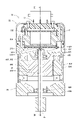
- FIG. 2 is a cross-sectional view of a drive device according to one embodiment
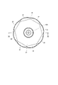
- FIG. 3 is a cross-sectional view taken along line III-III in FIG.
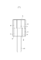
- FIG. 4 is a side view of a rotor according to one embodiment
- FIG. 5A is a plan view for explaining the arrangement of the first-stage magnets
- FIG. 5B is a plan view for explaining the arrangement of the second stage magnets
- FIG. 6 is an explanatory diagram illustrating the arrangement of the first-stage magnets and the second-stage magnets when viewed from the axial direction in one embodiment.
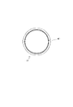
- FIG. 7 is a side view showing a rotor cover before press fitting according to one embodiment
- 8 is a view in the direction of arrow VIII in FIG. 7
- FIG. 9 is a schematic diagram illustrating the positional relationship between the rotor and the rotor cover according to one embodiment
- FIG. 10 is a plan view showing a rotor and rotor cover according to one embodiment
- FIG. 11 is a cross-sectional view taken along line XI-XI in FIG.
- FIG. 11 is a cross-sectional view taken along line XI-XI in FIG.
- FIG. 11 is a
- the driving device 10 includes an ECU 20 and a motor 80 as a rotating electric machine, and is applied to an electric power steering device 8, which is a steering device for assisting steering operation of a vehicle, for example.
- FIG. 1 shows the configuration of a steering system 90 that includes an electric power steering device 8.
- the steering system 90 includes a steering wheel 91 that is a steering member, a steering shaft 92, a pinion gear 96, a rack shaft 97, wheels 98, an electric power steering device 8, and the like.
- a steering wheel 91 is connected to a steering shaft 92 .
- the steering shaft 92 is provided with a torque sensor 94 that detects a steering torque Ts.
- a pinion gear 96 is provided at the tip of the steering shaft 92 .
- the pinion gear 96 meshes with the rack shaft 97 .
- a pair of wheels 98 are connected to both ends of the rack shaft 97 via tie rods or the like.
- the electric power steering device 8 includes a motor 80, a reduction gear 89 as a power transmission unit that decelerates the rotation of the motor 80 and transmits it to the steering shaft 92, the ECU 20, and the like.
- the electric power steering device 8 of this embodiment is of a so-called "column assist type", and the steering shaft 92 can be said to be driven.
- a so-called “rack assist type” that transmits the rotation of the motor 80 to the rack shaft 97 may be used.
- the motor 80 outputs part or all of the torque required for steering, and is driven by electric power supplied from a battery (not shown) to move the reduction gear 89 forward. reverse rotation.
- the drive device 10 is provided with an ECU 20 on one side of the motor 80 in the axial direction, and is a so-called "machine-electric integrated type".
- the ECU 20 and the motor 80 can be efficiently arranged in a vehicle with limited mounting space.
- the ECU 20 is arranged coaxially with the axis Ax of the shaft 870 on the side opposite to the output shaft of the motor 80 .
- the ECU 20 may be provided on the output shaft side of the motor 80 or may be provided separately from the motor 80 .
- the motor 80 includes a stator 840, a rotor 30, a housing 830 that accommodates them, and the like.
- a stator 840 is fixed to the housing 830 and has the motor windings 801, 802 wound thereon.
- Rotor 30 is provided radially inside stator 840 and is provided rotatably relative to stator 840 .
- the shaft 870 is fitted into the rotor 30 and rotates together with the rotor 30 .
- Shaft 870 is rotatably supported in housing 830 by bearings 835 and 836 .
- An end portion of the shaft 870 on the side of the ECU 20 protrudes from the housing 830 toward the side of the ECU 20 .
- a magnet 875 is provided at the end of the shaft 870 on the side of the ECU 20 .
- Magnet 857 is held on shaft 870 by a magnet holder 876 .
- the housing 830 has a tubular case 834 , a rear frame end 837 provided at one end of the case 834 , and a front frame end 838 provided at the other end of the case 834 .
- the rear frame end 837 is formed with lead wire insertion holes through which lead wires 803 and 804 connected to respective phases of the motor windings 801 and 802 are inserted.
- the ECU 20 includes a control board 230, a power board 235, power modules 241 and 242, a heat sink 245, and the like.
- the control board 230 is formed in a substantially rectangular shape, and is fixed to the surface of the heat sink 245 on the side of the motor 80 with bolts or the like.
- the power board 235 is formed in a substantially rectangular shape and is fixed to the surface of the heat sink 245 opposite to the motor 80 with bolts or the like.
- the heat sink 245 is fixed to the rear frame end 837.
- the heat sink 63 and the rear frame end 837 may be integrated or separate.
- the heat sink 245 is made of a metal having good thermal conductivity such as aluminum, and the power modules 241 and 242 are provided on its side surfaces so as to be capable of dissipating heat. That is, in this embodiment, the power modules 241 and 242 are vertically arranged along the axial direction of the motor 80 .
- the power modules 241 and 242 are provided with switching elements and the like constituting inverters related to energization control for the motor windings 801 and 802, respectively, and are connected to the motor windings 801 and 802 via lead wires 803 and 804. . Also, the power modules 241 and 242 are connected to the control board 230 and the power board 235 .
- the cover 21 is formed in a substantially cylindrical shape with a bottom and fits radially outward of the rear frame end 837 .
- the cover 21 is provided so as to cover the boards 230 and 235 and the power modules 241 and 242 .
- a rotation angle sensor 53 is mounted on the surface of the control board 230 facing the motor 80 at a position facing the magnet 875 .
- the connector unit 22 is fixed to the cover 21 with screws or the like.
- the rotor 30 has rotor cores 31, 32 and magnets 33, .
- the rotor cores 31 and 32 are formed in a substantially regular octagonal shape in a plan view, and are formed by laminating thin plates made of, for example, iron.
- the rotor core 32 is provided on the motor 80 side, and the rotor core 31 is provided on the connector unit 22 side.
- the plurality of first-stage magnets 33 are of a segment type having an arcuate radially outer side, and are fixed to the radially outer side of the rotor core 31 .
- the plurality of second-stage magnets 34 are of a segment type whose radially outer side is formed in an arc shape, and are fixed to the radially outer side of the rotor core 32 .
- the motor 80 is a so-called SPM motor in which magnets 33 and 34 are attached to the outer peripheral surfaces of rotor cores 31 and 202, respectively.
- the first stage magnet 33 and the second stage magnet 34 are arranged such that their radial positions are shifted in the circumferential direction by the skew angle ⁇ s. That is, the rotor 30 is a step skew rotor.
- the magnets 33, 34 are fixed to the rotor cores 31, 32 by a rotor cover 40 press-fitted radially outward (see FIGS. 9 to 13). In this embodiment, no bonding member such as adhesive is provided between the magnets 33 and 34 and the rotor cores 31 and 32, and they are fixed without bonding.
- each of the magnets 33 and 34 has a chamfered end portion on the outer side in the circumferential direction. Further, by increasing the radii of curvature of the magnets 33 and 34 so that the end of the magnet 33 is located inside the outer diameter of the magnet 34 when the rotor 30 is projected in the axial direction, interference with the rotor cover 40 is achieved. I try not to. As a result, the step between the first-stage magnet 33 and the second-stage magnet 34 is reduced, and the rotor cover 40 is less likely to get caught when it is press-fitted in the axial direction, making it easier to press-fit.
- the rotor cover 40 is made of a non-magnetic material and has a substantially cylindrical shape.
- the rotor cover 40 is deformable by being press-fitted onto the rotor 30 and is formed to have a thickness that does not cause buckling due to the press-fitting.
- the rotor cover 40 has a circular inner diameter 401 before being press-fitted.
- the rotor cover 40 is a stepped cylindrical member having a first large diameter portion 41, a small diameter portion 45, a second large diameter portion 42, and a tapered portion 43 from one side in the axial direction.
- the magnets 33 and 34 are fixed to the rotor cores 31 and 32 by press-fitting the rotor cover 40 into the rotor 30 from the tapered portion 43 side.
- the small-diameter portion 45 is provided in the central portion in the axial direction so as to straddle the first-stage magnet 33 and the second-stage magnet 34 .
- the large diameter portions 41 and 42 are provided on both sides of the small diameter portion 45 in the axial direction.
- the tapered portion 43 is formed so as to expand radially outward from the second large diameter portion 42 . As a result, press-fitting from the tapered portion 43 side facilitates press-fitting.
- Both axial ends of the rotor cover 40 are bent radially inward after being press-fitted into the rotor 30 so that the magnets 33 and 34 are not exposed.
- the small-diameter portion length which is the axial length of the small-diameter portion 45
- the rotor length which is the axial length of the rotor 30, is L2
- the small-diameter portion length L1 is the rotor length. It is formed over half or more of L2 (equation (1)).
- the rotor length L2 can also be regarded as the length from one end of the first stage magnet 33 to the other end of the second stage magnet 34 .
- the first stage magnet 33 and the second stage magnet 34 have the same axial length and are provided on both sides of the rotor 30 with the axial center position C therebetween.
- the small diameter portion 45 can hold more than half of the axial length of the magnets 33 and 34. . Thereby, inclination of the magnets 33 and 34 can be suppressed.
- FIG. 9 for explanation, the difference between the large-diameter portions 41 and 42 and the small-diameter portion 45 is emphasized so as to be clear. Further, in FIG. 11 described later, description of a step between the large-diameter portions 41 and 42 and the small-diameter portion 45 is omitted.
- the inner periphery of the rotor cover has a polygonal shape
- the protrusion of the first stage magnet 33 and the corner of the inner periphery of the cover are press-fitted together
- the protrusion of the second stage magnet 33 and the corner of the inner periphery of the cover are press-fitted. Press-fitting becomes difficult because the positions of the projections of the rotor cover do not match.
- the inner diameter 401 of the rotor cover 40 before press-fitting circular, it becomes possible to press-fit the magnets 33 and 34 while deforming along the outer diameter. Therefore, the inner diameter 401 of the rotor cover 40 after press-fitting is not a simple circle but a shape along the outer edges of the magnets 33 and 34 . Further, by making the radius of curvature of each of the magnets 33 and 34 as large as possible, the difference in level between the first stage magnet 33 and the second stage magnet 34 is reduced, and the second stage magnet 34 is less likely to be caught. , making it easier to press fit.
- FIG. 12 is a cross-sectional view of the first large diameter portion 41
- FIG. 13 is a cross-sectional view of the small diameter portion 45.
- FIG. 12 and 13 are diagrams for explaining the definitions of the radius ⁇ R0 of the circumscribed circle of the rotor 30, the minimum radius ⁇ R1 of the small diameter portion, and the minimum radius ⁇ R2 of the large diameter portion, and do not necessarily match the actual sizes. Also, since the size of the second large diameter portion 42 is the same as that of the first large diameter portion 41, description thereof will be omitted. As shown in FIGS. 12 and 13, when the rotor cover 40 is press-fitted, the rotor cover 40 is spaced apart along the outer diameter at the center of each magnet 33 .
- the distance between the axis Ax and the top of the magnet 33 is the circumscribed circle radius ⁇ R0
- the minimum radius of the rotor cover 40 at the small diameter portion 45 is the small diameter portion minimum radius ⁇ R1
- the minimum radius of the rotor cover 40 at the large diameter portion 41 is the large diameter portion. Let the minimum radius be ⁇ R2.
- the minimum radius of the rotor cover 40 at the large-diameter portion 41 and the small-diameter portion 45 is the length that connects the center point of the abutting points between the tops of the two magnets 33 adjacent in the circumferential direction and the axis Ax.
- the minimum radius ⁇ R2 of the large diameter portion is less than the radius ⁇ R0 of the circumscribed circle, and the minimum radius ⁇ R1 of the small diameter portion is smaller than the minimum radius ⁇ R2 of the large diameter portion (see formula (2)).
- the rotor cover 40 is cylindrical, has a small-diameter portion 45 at the center in the axial direction, and large-diameter portions 41 and 42 at both ends. It is fixed to the rotor cores 31 and 32 with a less. As a result, the portion where the rotor cover 40 is press-fitted to the magnets 33 and 34 can be minimized, so that assembly can be facilitated.
- the rotor 30 of the present embodiment is a step skew rotor, and by forming the center of the rotor cover 40 as the small diameter portion 45, both the first step magnets 33 and the second step magnets 34 can be fixed at the same time. can. Further, by forming the large-diameter portions 41 and 42 on the outer side in the axial direction of the rotor cover 40, the rotor cover 40 can be formed by deep drawing.
- the motor 80 includes the housing 830, the stator 840, the shaft 870, the rotor 30, and the rotor cover 40.
- Stator 840 is non-rotatably fixed to housing 830 .
- Shaft 870 is rotatably supported by housing 830 .
- the rotor 30 has rotor cores 31 and 32 and multiple stages of magnets 33 and 34 which are provided radially outwardly of the rotor cores 31 and 32 while being displaced in the circumferential direction according to the skew angle, and rotates integrally with the shaft 870 .
- the rotor cores 31 and 32 are arranged to be shifted in the circumferential direction according to the skew angle, and the magnets 33 and 34 are provided outside the rotor cores 31 and 32, respectively, so that the magnets 33 and 34 are arranged at the skew angle. They are arranged staggered.
- the rotor cover 40 includes a first large-diameter portion 41 provided on one end side in the axial direction, a second large-diameter portion 42 provided on the other end side in the axial direction, and the first large-diameter portion 41 and the second large-diameter portion. 42 and axially adjacent magnets 33 and 34 have a small-diameter portion 45 having a diameter smaller than that of the first large-diameter portion 41 and the second large-diameter portion 42. It is press-fitted and fixed radially outward. Thus, one rotor cover 40 can appropriately hold the magnets 33 and 34 in multiple stages. In addition, by increasing the diameter of both ends in the axial direction, the press-fitting load can be reduced.
- ⁇ R0 is the radius of the circumscribed circle of the rotor 30
- ⁇ R1 is the minimum radius of the small diameter portion 45
- ⁇ R2 is the minimum radius of the first large diameter portion 41 and the second large diameter portion 42
- the axial length of the small diameter portion 45 is 1 ⁇ 2 or more of the axial length of the rotor 30 .
- Both ends of the magnets 33 and 34 in the circumferential direction are chamfered. As a result, the difference in level between the first-stage magnet 33 and the second-stage magnet 34 is reduced, so that the rotor cover 40 can be less likely to be caught when it is press-fitted, and assembly can be facilitated.
- the axial end of the rotor cover is provided with a tapered portion. In other embodiments, a tapered portion may not be provided.
- the magnets are held on the rotor by the rotor cover without adhesive. In another embodiment, the magnets may be adhered to the rotor using an adhesive member such as an adhesive and then held by the rotor cover.
- each stage is composed of eight magnets. In other embodiments, the number of magnets in each stage may be other than eight.
- the rotor in the above embodiment is a two-stage skew rotor. In other embodiments, the number of stages of the stage skew rotor may be three or more.
- the rotating electric machine is applied to the electric power steering device.
- the rotary electric machine may be applied to a device other than the electric power steering device, such as a steering device or a reaction force device in a steer-by-wire system.
- a device other than the electric power steering device such as a steering device or a reaction force device in a steer-by-wire system.
- the present disclosure is by no means limited to the above embodiments, and can be implemented in various forms without departing from the scope of the present disclosure.
Landscapes
- Engineering & Computer Science (AREA)
- Power Engineering (AREA)
- Permanent Field Magnets Of Synchronous Machinery (AREA)
Applications Claiming Priority (2)
| Application Number | Priority Date | Filing Date | Title |
|---|---|---|---|
| JP2021-018405 | 2021-02-08 | ||
| JP2021018405A JP7463979B2 (ja) | 2021-02-08 | 2021-02-08 | 回転電機 |
Publications (1)
| Publication Number | Publication Date |
|---|---|
| WO2022168896A1 true WO2022168896A1 (ja) | 2022-08-11 |
Family
ID=82742360
Family Applications (1)
| Application Number | Title | Priority Date | Filing Date |
|---|---|---|---|
| PCT/JP2022/004149 Ceased WO2022168896A1 (ja) | 2021-02-08 | 2022-02-03 | 回転電機 |
Country Status (2)
| Country | Link |
|---|---|
| JP (1) | JP7463979B2 (https=) |
| WO (1) | WO2022168896A1 (https=) |
Cited By (1)
| Publication number | Priority date | Publication date | Assignee | Title |
|---|---|---|---|---|
| WO2026026071A1 (zh) * | 2024-07-30 | 2026-02-05 | 安徽威灵汽车部件有限公司 | 电动助力转向电机、电动助力转向系统和车辆 |
Citations (4)
| Publication number | Priority date | Publication date | Assignee | Title |
|---|---|---|---|---|
| JP2014030352A (ja) * | 2013-10-07 | 2014-02-13 | Asmo Co Ltd | ロータの製造方法 |
| JP2014072971A (ja) * | 2012-09-28 | 2014-04-21 | Toshiba Industrial Products Manufacturing Corp | 表面磁石貼付型回転電機の回転子とその製造方法 |
| JP5528552B2 (ja) * | 2010-06-10 | 2014-06-25 | 三菱電機株式会社 | 回転電機の回転子の製造方法 |
| JP2017079596A (ja) * | 2016-12-26 | 2017-04-27 | 日本電産株式会社 | ロータユニット |
-
2021
- 2021-02-08 JP JP2021018405A patent/JP7463979B2/ja active Active
-
2022
- 2022-02-03 WO PCT/JP2022/004149 patent/WO2022168896A1/ja not_active Ceased
Patent Citations (4)
| Publication number | Priority date | Publication date | Assignee | Title |
|---|---|---|---|---|
| JP5528552B2 (ja) * | 2010-06-10 | 2014-06-25 | 三菱電機株式会社 | 回転電機の回転子の製造方法 |
| JP2014072971A (ja) * | 2012-09-28 | 2014-04-21 | Toshiba Industrial Products Manufacturing Corp | 表面磁石貼付型回転電機の回転子とその製造方法 |
| JP2014030352A (ja) * | 2013-10-07 | 2014-02-13 | Asmo Co Ltd | ロータの製造方法 |
| JP2017079596A (ja) * | 2016-12-26 | 2017-04-27 | 日本電産株式会社 | ロータユニット |
Cited By (1)
| Publication number | Priority date | Publication date | Assignee | Title |
|---|---|---|---|---|
| WO2026026071A1 (zh) * | 2024-07-30 | 2026-02-05 | 安徽威灵汽车部件有限公司 | 电动助力转向电机、电动助力转向系统和车辆 |
Also Published As
| Publication number | Publication date |
|---|---|
| JP2022121192A (ja) | 2022-08-19 |
| JP7463979B2 (ja) | 2024-04-09 |
Similar Documents
| Publication | Publication Date | Title |
|---|---|---|
| CN101527486B (zh) | 无刷马达 | |
| JP5359859B2 (ja) | ブラシレスモータ用ロータ、ブラシレスモータ及び電動パワーステアリング装置、並びにブラシレスモータ用ロータの製造方法 | |
| CN110546857B (zh) | 马达和电动助力转向装置 | |
| JP4512128B2 (ja) | モータの回転角検出装置 | |
| CN108781004A (zh) | 旋转电机、电动助力转向装置及旋转电机的制造方法 | |
| JP2014033540A (ja) | 回転電機、および、これを用いた電動パワーステアリング装置 | |
| JPWO2008050637A1 (ja) | ブラシレスモータ | |
| JP2009044880A (ja) | モータ及び電動パワーステアリング装置 | |
| CN101379674A (zh) | 电动动力转向装置 | |
| JP2012090496A (ja) | モータ及び電動パワーステアリング装置 | |
| JP2012090495A (ja) | モータ及び電動パワーステアリング装置 | |
| JP2012192787A (ja) | アクチュエータ及び電動パワーステアリング装置 | |
| WO2022168896A1 (ja) | 回転電機 | |
| JP2009153269A (ja) | ブラシレスモータ | |
| JP2005065388A (ja) | 永久磁石回転電機 | |
| JP5470913B2 (ja) | モータコア、これを用いるモータコアユニット、ブラシレスモータ及びこれを用いる電動パワーステアリング装置、並びにモータコアユニットの製造方法 | |
| JP2006050816A (ja) | ブラシレスモータ | |
| JP7330011B2 (ja) | ロータ、モータ及びブラシレスワイパーモータ | |
| JP5413619B2 (ja) | 電動パワーステアリング装置 | |
| JP2009153268A (ja) | ブラシレスモータ | |
| JP7567531B2 (ja) | ロータ及びそれを備える減速装置 | |
| JP5037257B2 (ja) | ブラシレスモータ | |
| JP6003066B2 (ja) | 電動機、電動機ユニット及び電動パワーステアリング装置 | |
| JP2009044799A (ja) | ブラシレスモータ | |
| JP5037256B2 (ja) | ブラシレスモータ |
Legal Events
| Date | Code | Title | Description |
|---|---|---|---|
| 121 | Ep: the epo has been informed by wipo that ep was designated in this application |
Ref document number: 22749767 Country of ref document: EP Kind code of ref document: A1 |
|
| NENP | Non-entry into the national phase |
Ref country code: DE |
|
| 122 | Ep: pct application non-entry in european phase |
Ref document number: 22749767 Country of ref document: EP Kind code of ref document: A1 |