WO2022168360A1 - 電気化学センサ - Google Patents
電気化学センサ Download PDFInfo
- Publication number
- WO2022168360A1 WO2022168360A1 PCT/JP2021/033977 JP2021033977W WO2022168360A1 WO 2022168360 A1 WO2022168360 A1 WO 2022168360A1 JP 2021033977 W JP2021033977 W JP 2021033977W WO 2022168360 A1 WO2022168360 A1 WO 2022168360A1
- Authority
- WO
- WIPO (PCT)
- Prior art keywords
- electrode
- sensor
- cover member
- working electrode
- sensor electrode
- Prior art date
- Legal status (The legal status is an assumption and is not a legal conclusion. Google has not performed a legal analysis and makes no representation as to the accuracy of the status listed.)
- Ceased
Links
Images


Classifications
-
- G—PHYSICS
- G01—MEASURING; TESTING
- G01N—INVESTIGATING OR ANALYSING MATERIALS BY DETERMINING THEIR CHEMICAL OR PHYSICAL PROPERTIES
- G01N27/00—Investigating or analysing materials by the use of electric, electrochemical, or magnetic means
- G01N27/26—Investigating or analysing materials by the use of electric, electrochemical, or magnetic means by investigating electrochemical variables; by using electrolysis or electrophoresis
- G01N27/28—Electrolytic cell components
- G01N27/30—Electrodes, e.g. test electrodes; Half-cells
-
- G—PHYSICS
- G01—MEASURING; TESTING
- G01N—INVESTIGATING OR ANALYSING MATERIALS BY DETERMINING THEIR CHEMICAL OR PHYSICAL PROPERTIES
- G01N27/00—Investigating or analysing materials by the use of electric, electrochemical, or magnetic means
- G01N27/26—Investigating or analysing materials by the use of electric, electrochemical, or magnetic means by investigating electrochemical variables; by using electrolysis or electrophoresis
- G01N27/416—Systems
- G01N27/48—Systems using polarography, i.e. measuring changes in current under a slowly-varying voltage
Definitions
- the present invention relates to an electrochemical sensor that electrochemically detects a specific component in a test liquid.
- Electrochemical sensors that detect a specific component in a test solution by using an electrochemical reaction caused by applying a voltage to electrodes are affected by the electrode area. It has been proposed to regulate the area of an electrode made of a metal film by using a tape material having
- Some electrochemical sensors are configured with chip-shaped electrodes instead of electrodes made of metal films.
- a diamond tip having a diamond film supported by a supporting member made of silicon or a silicon compound is provided, and a specific component in a test solution is detected by utilizing an oxidation-reduction reaction occurring in the diamond tip.
- Some are configured to do so.
- chip-shaped electrode it is not always easy to achieve high accuracy in processing to form a chip, so there is a possibility that the electrode area will vary, and this will affect the detection result.
- the present disclosure provides a technique that enables the surface of the electrode to be appropriately covered with a cover member, even if it is a chip-shaped sensor electrode, and to reliably regulate the exposed electrode area.
- a substrate having a sensor mounting surface; a chip-shaped sensor electrode arranged on the sensor mounting surface; a pedestal provided incidentally to the sensor electrode; a cover member arranged to cover the sensor electrode; with
- the sensor electrode is configured such that the surface opposite to the surface facing the sensor mounting surface functions as a detection surface for detecting a specific component in the test liquid,
- the pedestal has a contact surface arranged so that a height position from the sensor mounting surface is aligned with the detection surface,
- the cover member is fixed in position by coming into contact with the detection surface and the contact surface, and has an opening that exposes a partial area of the detection surface in a fixed position state.
- a chemical sensor is provided.
- the electrode surface can be appropriately covered with the cover member, and the exposed electrode area can be reliably regulated.
- FIG. 1 is a perspective view schematically showing an electrode configuration example in an electrochemical sensor according to a first embodiment of the present disclosure
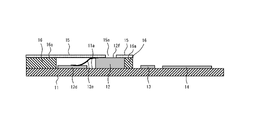
- FIG. BRIEF DESCRIPTION OF THE DRAWINGS FIG. 1 is a side cross-sectional view schematically showing an example configuration of a main part of an electrochemical sensor according to a first embodiment of the present disclosure
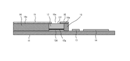
- FIG. 2 is a side cross-sectional view schematically showing a configuration example of a main part of an electrochemical sensor according to a second embodiment of the present disclosure
- FIG. 10 is a side cross-sectional view schematically showing a configuration example of a main part of an electrochemical sensor according to a third embodiment of the present disclosure
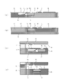
- FIG. 11 is a side cross-sectional view schematically showing a configuration example of a main part of an electrochemical sensor according to a fourth embodiment of the present disclosure
- the electrochemical sensor according to this embodiment electrochemically detects a specific component in a test liquid.
- a case of detecting uric acid contained in urine collected from a subject is taken as an example. That is, in the present embodiment, urine collected from a subject is exemplified as the test fluid, and uric acid contained in urine is exemplified as the specific component to be detected.
- the concentration of uric acid in urine shall be detected, for example, by electrolyzing the substances contained in urine under specific conditions and using the electrochemical reaction (for example, oxidation-reduction reaction) that occurs at that time.
- the concentration of uric acid in urine is detected by a three-electrode method will be taken as an example.
- the three-electrode method is a method of performing electrochemical measurement by combining three electrodes, a working electrode, a counter (counter) electrode, and a reference electrode.
- FIG. 1 is a perspective view schematically showing an electrode configuration example in an electrochemical sensor according to the first embodiment of the present disclosure.
- the electrochemical sensor according to the present embodiment has a working electrode 12 which is a chip-shaped sensor electrode and a counter electrode as a second sensor electrode separate from the sensor electrode, on a substrate 11. 13 and a reference electrode 14 are arranged.
- the substrate 11 supports the working electrode 12, the counter electrode 13, and the reference electrode 14, and is formed of, for example, a strip-shaped plate member in plan view, and at least the working electrode 12 is mounted on one end side in the longitudinal direction. It has a sensor mounting surface 11a. The other end in the longitudinal direction is configured to be connectable to a measuring instrument (not shown) such as a potentiostat that performs a predetermined voltage sweep operation on the working electrode 12, counter electrode 13 and reference electrode .
- a measuring instrument such as a potentiostat that performs a predetermined voltage sweep operation on the working electrode 12, counter electrode 13 and reference electrode .
- the base material 11 is made of an insulating material.
- the base material 11 can be formed of an insulating material such as an insulating resin material, ceramic, glass, plastic, combustible material, biodegradable material, non-woven fabric, or paper.
- an insulating material such as an insulating resin material, ceramic, glass, plastic, combustible material, biodegradable material, non-woven fabric, or paper.
- polyethylene (PE), polyethylene terephthalate (PET), epoxy resin, etc. can be preferably used.
- a semiconductor base material or a metal base material having an insulating property for the sensor mounting surface 11a can be used.
- a wiring (not shown) is provided on the base material 11 .
- the wires correspond to the working electrode 12, the counter electrode 13 and the reference electrode 14, respectively, and are arranged so as to individually connect them to the measuring device.
- the wiring can be formed using a conductive metal material such as copper (Cu), aluminum (Al), gold (Au), and platinum (Pt).
- the working electrode 12 is a chip-shaped sensor electrode, and when a predetermined voltage is applied in a state where urine, which is a sample liquid, exists between the working electrode 12 and the counter electrode 13, the surface of the working electrode 12 is configured to cause an oxidation-reduction reaction at Specifically, the working electrode 12 has, for example, a diamond film 12a that causes an oxidation-reduction reaction in response to an applied voltage in a state where urine is adhered, and a support member 12b that supports the diamond film 12a. It is configured. In that case, the working electrode 12 is arranged such that the support member 12b is positioned on the substrate 11 side.
- the surface opposite to the sensor mounting surface 11a of the substrate 11 (that is, the surface of the diamond film 12a) functions as a detection surface for detecting uric acid in urine.
- a chip-shaped sensor electrode having such a diamond film 12a is also called a "diamond chip”.
- the diamond film 12a forming the diamond tip is a polycrystalline film.
- the diamond film 12a may be a diamond-like carbon (DLC) film, a glassy carbon (GC) film, or the like.
- the term "diamond film” includes polycrystalline diamond films, DLC films, GC films, and combinations thereof.
- the diamond film 12a is preferably of p-type. To be p-type, the diamond film 12a preferably contains an element such as boron (B) at a concentration of 1 ⁇ 10 19 cm ⁇ 3 or more and 1 ⁇ 10 22 cm ⁇ 3 or less.
- the B concentration in the diamond film 12a can be measured, for example, by secondary ion mass spectrometry (SIMS).
- SIMS secondary ion mass spectrometry
- the diamond film 12a is formed by a chemical vapor deposition (CVD) method such as a hot filament CVD method or a plasma CVD method, or a physical vapor deposition (PVD) method such as an ion beam method or an ionization deposition method. ) or the like to grow (synthesize).
- CVD chemical vapor deposition
- PVD physical vapor deposition
- a tungsten filament for example, can be used as the filament.
- the thickness of the diamond film 12a can be, for example, 0.5 ⁇ m or more and 10 ⁇ m or less, preferably 2 ⁇ m or more and 4 ⁇ m or less.
- the support member 12b that constitutes the diamond tip is formed using a material (different material) other than diamond.
- the support member 12b is preferably made of a conductive material.
- the support member 12b is preferably made of, for example, silicon (Si) alone, a silicon compound, or a metal substrate. That is, the support member 12b is preferably made of a silicon substrate or a metal substrate.
- the support member 12b is preferably made of any one of a single-crystal Si substrate, a polycrystalline Si substrate, a silicon carbide substrate (SiC substrate), and a metal substrate.
- the thickness of the support member 12b can be, for example, 0.3 mm or more and 0.5 mm or less, preferably about 0.4 mm.
- the counter electrode 13 is provided near the working electrode 12 .
- an electrode made of metal such as platinum (Pt), gold (Au), copper (Cu), palladium (Pd), nickel (Ni), silver (Ag), diamond electrode, boron-doped diamond A (BDD) electrode, a carbon electrode, or the like can be used.
- the counter electrode 13 can be formed by known methods such as a semi-additive method and a subtractive method.
- the working electrode 12 and the counter electrode 13 detect a predetermined component in the test liquid (predetermined A redox reaction of the reactive species (eg, uric acid) takes place, resulting in a current flow between the working electrode 12 and the counter electrode 13 .
- the counter electrode 13 is an electrode for causing the current generated by the electrochemical reaction to flow to the working electrode 12 .
- the reference electrode 14 is an electrode that serves as a reference when determining the potential of the working electrode 12 .
- a silver/silver chloride (Ag/AgCl) electrode or the like can be used as the reference electrode 14.
- a standard hydrogen electrode, a reversible hydrogen electrode, a palladium/hydrogen electrode, a saturated calomel electrode, a carbon electrode, a diamond electrode, a BDD electrode, or the like can be used.
- an electrode made of metal such as Pt, Au, Cu, Pd, Ni, Ag, or the like can be used.
- the reference electrode 14 can be formed by a known technique such as dispensing or screen printing.
- the electrochemical sensor includes the working electrode 12, the counter electrode 13 and the reference electrode 14 to detect the concentration of uric acid in urine by the three-electrode method.
- the working electrode 12 is composed of a diamond tip with a thickness of about 0.4 mm, for example.
- the diamond chip due to the hardness of the diamond film 12a, it is not always easy to increase the accuracy of the contour processing (scribing) for making chips. Therefore, there is a possibility that the electrode area of the working electrode 12 may vary, which may affect the detection result.
- the electrochemical sensor according to this embodiment includes a cover member 15 arranged to cover the detection surface side of the diamond film 12a in the working electrode 12. As shown in FIG.
- the cover member 15 has an opening 15a that exposes a partial area 12c on the detection surface of the diamond film 12a. As a result, the exposed area of the detection surface of the working electrode 12 is restricted by the opening 15 a of the cover member 15 . Therefore, if the opening 15a is formed with high precision, it is possible to prevent the detection result from being affected even if the processing precision of the diamond tip is low.
- the cover member 15 is easy to attach to cover the working electrode 12 and that it is easy to form and process the opening 15a with high accuracy. Moreover, it is preferable that the cover member 15 contributes to the improvement of the mass productivity of the electrochemical sensor, the cost reduction, and the like.
- the cover member 15 is formed using, for example, an adhesive tape material. More specifically, the cover member 15 can be configured by including an insulating sheet material and an adhesive layer formed on at least one surface of the sheet material.
- the sheet material non-woven fabric, polyester, polyethylene terephthalate, polystyrene, etc. can be used. Hard plastics, especially polyethylene terephthalate, which can be cut easily and accurately with a knife or the like when forming the opening 15a, are used. is preferred.
- An acrylic adhesive, a rubber adhesive, or the like can be used for the adhesive layer.
- the thickness of the sheet material and adhesive layer is not particularly limited.
- Such a sheet-shaped cover member 15 can be easily attached to cover the working electrode 12, and the opening 15a can be easily formed with high accuracy. This will contribute to improvement and cost reduction.
- a case where the cover member 15 is formed of an adhesive tape material is taken as an example, but the cover member 15 is not necessarily limited to this, and other members may be used as long as they can be attached so as to cover the working electrode 12. (eg, an adhesive, an adhesive tape material, or a similar material).
- an adhesive is used to fix the position of the cover member 15, there is a problem of decreased sensitivity due to leakage of the adhesive onto the detection surface. can.
- a thermosetting adhesive is used, heating at, for example, 90° C.
- the opening 15a of the cover member 15 is preferably formed with a stable and accurate shape and size. Specifically, if the cover member 15 is in the form of a sheet such as an adhesive tape material, the opening 15a can be formed by using a punching die, and the existing technology can be used to improve the processing accuracy. can be easily controlled, so that it can be stably formed in an accurate shape and size.
- the opening 15a is not limited to a specific planar shape as long as it can be formed in a stable and accurate shape and size, but is preferably formed in a non-flat planar shape.
- a non-flat planar shape means a shape with a low degree of flatness such as a square or a circle, rather than a flat shape such as a rectangle or an ellipse.
- the flat shape may cause non-uniform electric field distribution in the partial region 12c exposed by the opening 15a, but the non-flat planar shape can suppress such non-uniform electric field distribution.
- the planar shape of the opening 15a is circular.
- the cover member 15 can be in close contact with the detection surface of the diamond film 12a. This is because if the detection surface is not in close contact with the detection surface, the test liquid may enter the gap and the area of the working electrode 12 in contact with the test liquid may fluctuate, which may affect the detection result. .
- the working electrode 12 is formed in a chip shape with a thickness of, for example, about 0.4 mm. Therefore, when the sheet-shaped cover member 15 is used to cover the working electrode 12, the working electrode 12 may be in contact with the detection surface of the working electrode 12 while the cover member 15 is brought into close contact with the detection surface of the working electrode 12 due to the influence of steps and the like caused by the tip thickness of the working electrode 12. It is not necessarily easy to appropriately cover the electrode surface (specifically, the surface other than the partial region 12c, particularly the side surface of the working electrode 12).
- the electrochemical sensor according to this embodiment is configured with a pedestal portion 16 attached to the working electrode 12 .
- FIG. 2 is a side cross-sectional view schematically showing a configuration example of the main part of the electrochemical sensor according to the first embodiment of the present disclosure.
- the pedestal 16 is formed of a member separate from the base material 11, and attached to the base material 11 along with the working electrode 12. is configured as More specifically, the pedestal part 16 is mounted on the sensor mounting surface 11a of the base material 11 so as to surround the arrangement space of the working electrode 12 .
- the pedestal portion 16 which is a separate member from the base material 11, is formed to have the same thickness as the chip thickness of the working electrode 12. That is, the pedestal portion 16 is configured to have the contact surface 16a arranged so that the height position from the sensor mounting surface 11a of the substrate 11 is aligned with the detection surface 12f of the working electrode 12. As shown in FIG. As a result, even if the cover member 15 covering the working electrode 12 is formed in a sheet shape, the adhesive layer that constitutes the cover member 15 can be applied to the detection surface 12f of the working electrode 12 (in particular, a part of the detection surface 12f). By contacting the contact surface 16a of the pedestal portion 16 and the portion other than the region 12c, the position is fixed.
- Such a pedestal portion 16 is made of an insulating material, like the base material 11 .
- the pedestal 16 can be made of an insulating material such as an insulating resin material, ceramic, glass, plastic, combustible material, biodegradable material, non-woven fabric, or paper.
- PE, PET, epoxy resin, etc. can be preferably used.
- a semiconductor base material or a metal base material configured to have insulating properties can be used.
- the pedestal portion 16 is formed as a separate member from the base material 11, it may be formed of the same material as the base material 11, or may be formed of a material different from that of the base material 11. . In either case, the pedestal 16 is mounted and fixed on the sensor mounting surface 11a of the substrate 11 using known techniques such as adhesion and welding.
- the working electrode 12 is electrically connected to the wiring portion 12d formed on the base material 11 by wire bonding, for example, using a conductive tape 12e.
- a connection mode even if the conductivity of the support member 12b constituting the working electrode 12 is low, the electric current generated by the electrochemical reaction with the sample liquid can be extracted satisfactorily.
- contact of the test liquid with the conductive tape 12e may adversely affect the reliability of the measurement. Therefore, on the sensor mounting surface 11a of the substrate 11, the pedestal portion 16 is arranged so as to surround the arrangement space including the working electrode 12, the wiring portion 12d and the conductive tape 12e.
- a cover member 15 is positioned so as to cover the arrangement space (that is, to prevent the sample liquid from entering the arrangement space). As a result, even in the case of wire bonding connection, it is possible to avoid the contact of the sample liquid, so that the reliability of the measurement can be improved.
- the height positions of the detection surface 12f of the working electrode 12 and the contact surface 16a of the pedestal portion 16 are aligned.
- the position of the cover member 15 is fixed. Therefore, even when the working electrode 12 is in the form of a chip and the cover member 15 is in the form of a sheet, the position of the cover member 15 can be appropriately and reliably fixed while ensuring the adhesion.
- the surface of the working electrode 12 other than the partial region 12c can be prevented from coming into contact with urine, which is the sample liquid.
- the electrochemical sensor according to this embodiment is constructed by arranging the counter electrode 13 and the reference electrode 14 separate from the working electrode 12 in parallel with the working electrode 12 . With such a parallel arrangement, it is possible to easily secure a sufficient distance between the working electrode 12 and the counter electrode 13 (that is, keep them away from each other), so that the electrochemical reaction ( For example, oxidation) can be suppressed from being affected by an electrochemical reaction (for example, reduction) proceeding at the counter electrode 13 .
- the electrochemical sensor To detect uric acid concentration, first connect the electrochemical sensor to a measuring instrument (potentiostat, etc.). Specifically, each wiring on the substrate 11 of the electrochemical sensor and the measuring device are electrically connected.
- the measuring device is configured to be able to perform a predetermined voltage sweeping operation, and has, for example, a voltage applying section, a current measuring section, a potential difference measuring section, and a potential adjusting section.
- the voltage applying section is configured to apply a voltage between the working electrode 12 and the counter electrode 13 when a predetermined circuit is formed by connecting wires.
- the current measurement unit is configured to measure the current generated by the oxidation-reduction reaction of uric acid.
- the potentiometric measuring portion is configured to measure the potential difference between the working electrode 12 and the reference electrode 14 .
- the potential adjustment unit is configured to keep the potential of the working electrode 12 constant with the potential of the reference electrode 14 as a reference, based on the potential difference measured by the potential difference measurement unit.
- the electrochemical sensor After connecting the electrochemical sensor and the measuring device, for example, urine, which is the sample liquid, is supplied to the electrochemical sensor.
- the working electrode 12 is covered with the cover member 15 , and only a partial region 12 c is exposed through the opening 15 a of the cover member 15 . Therefore, when urine is supplied, the urine contacts only the partial region 12c of the working electrode 12 and does not contact the surface of the working electrode 12 other than the partial region 12c, the conductive tape 12e, and the like.
- reaction current a current (reaction current) flows through the working electrode 12.
- the value of this reaction current is measured by, for example, cyclic voltammetry using the current measuring section of the measuring instrument. Examples of cyclic voltammetry conditions include a voltage range of 0 V to 1 V and a sweep rate of 0.1 V/s to 1 V/s.
- the value of the reaction current may be measured using techniques such as square wave voltammetry (rectangular wave voltammetry), differential pulse voltammetry, normal pulse voltammetry, and alternating current voltammetry.
- the potential difference (voltage difference) between the working electrode 12 and the reference electrode 14 is measured by the potential difference measurement unit of the measuring device while the sample liquid is in contact with urine.
- a cyclic voltammogram for example, is created from the value of the reaction current measured by the current measurement unit of the measuring instrument, and the current value at the oxidation peak is obtained. Based on the obtained oxidation peak current value and the value of the potential difference measured by the potential difference measurement part of the measuring device, the uric acid concentration in the test solution is calculated (quantified).
- the fact that the value of the reaction current is correlated with the uric acid concentration in the test fluid is disclosed in known literature (eg, Anal. Methods, 2018.10, 991-996, see FIGS. 3 and 4). Therefore, if the relationship between the reaction current value and the uric acid concentration is obtained in advance, the uric acid concentration can be quantified based on the measured reaction current value.
- the working electrode 12 is covered with a cover member 15 having an opening 15a. Therefore, the exposed area of the working electrode 12 is restricted by the opening 15 a in the cover member 15 regardless of the external shape of the working electrode 12 . Therefore, according to the present embodiment, even if the outer shape of the working electrode 12 varies, it is possible to suppress the influence thereof from affecting the detection result of the uric acid concentration in urine in the test fluid, and as a result, This is very preferable for improving the detection accuracy of uric acid concentration in urine.
- the working electrode 12 is additionally provided with a pedestal portion 16 .
- the cover member 15 does not need to be provided with a stepped shape or the like, or need to be provided with excessive rigidity, and a sheet-like member can be used.
- the working electrode 12 is appropriately and reliably covered with the cover member 15 while ensuring the adhesion, the cost of the cover member 15 is reduced, the formation of the opening 15a is facilitated, and the This is very effective in achieving high precision and the like.
- the pedestal portion 16 is formed of a member separate from the base material 11 . Therefore, a flat member can be used for each of the base material 11 and the pedestal portion 16, which is very useful for realizing cost reduction by reducing processing costs. It will be possible to sufficiently secure the degree of freedom of
- the working electrode 12 is composed of a diamond tip. That is, the working electrode 12 has a diamond film 12a that causes an oxidation-reduction reaction and a support member 12b that supports the diamond film 12a, and the diamond film 12a constitutes a detection surface. Therefore, it is possible to detect a specific component in the sample liquid (for example, uric acid in urine) with high sensitivity by oxidation-reduction reaction while utilizing the diamond film 12a that exhibits physically and chemically stable characteristics. Become.
- the cover member 15 is formed using an adhesive tape material, and has an insulating sheet material and an adhesive layer formed on at least one surface of the sheet material. is configured as Therefore, mounting for covering the working electrode 12 is easy, and, for example, by controlling the precision of the punching die, it is easy to increase the precision of the forming process of the opening 15a. Therefore, according to the present embodiment, it is possible to reliably regulate the exposed electrode area of the working electrode 12 . In addition, there is no leakage of the adhesive onto the detection surface of the working electrode 12, and the problem of reduced sensitivity due to the working electrode 12 does not occur. Furthermore, a room-temperature process becomes possible, and the feasibility of roll-to-roll mounting becomes high. Therefore, according to this embodiment, it contributes to the improvement of the mass productivity of the electrochemical sensor, the cost reduction, and the like.
- the opening 15a of the cover member 15 is formed in a non-flat planar shape. Therefore, it is possible to suppress unevenness in the electric field distribution in the partial region 12c of the working electrode 12 exposed by the opening 15a, which is preferable for improving the accuracy of the detection result by the working electrode 12. .
- the planar shape is formed in a circular shape, non-uniformity of the electric field distribution can be reliably suppressed, which is very preferable in terms of improving the accuracy of the detection result by the working electrode 12 .
- the working electrode 12 is electrically connected to the wiring portion 12d formed on the substrate 11 by wire bonding, for example, using a conductive tape 12e. With such a connection mode, even if the conductivity of the support member 12b constituting the working electrode 12 is low, the electric current generated by the electrochemical reaction with the sample liquid can be extracted satisfactorily.
- the counter electrode 13 and the reference electrode 14 as second sensor electrodes separate from the working electrode 12 are arranged in parallel with the working electrode 12 as the sensor electrode. With such a parallel arrangement, it is possible to easily secure a sufficient distance between the working electrode 12 and the counter electrode 13 (that is, keep them away from each other), so that the electrochemical reaction (for example, oxidation) can be suppressed from being affected by an electrochemical reaction (for example, reduction) proceeding at the counter electrode 13 .
- FIG. 3 is a side cross-sectional view schematically showing a configuration example of a main part of an electrochemical sensor according to the second embodiment of the present disclosure.
- the working electrode 12 is electrically connected to the wiring portion 12d formed on the substrate 11 by flip-chip bonding.
- the working electrode 12 is configured by a conductive support member 12b, and the connection terminal (not shown) formed on the support member 12b and the wiring portion 12d are connected by a solder material, silver (Ag ) are connected and fixed via a connecting material 12g such as paste or conductive adhesive tape.
- the working electrode 12 is electrically connected to the wiring portion 12d formed on the substrate 11 by flip-chip bonding.
- the current generated by the electrochemical reaction with the test liquid can be taken out through the support member 12b, so the electrochemical sensor can be miniaturized without requiring a space for arranging the conductive tape 12e. It is very useful for making Moreover, since the working electrode 12 is directly connected onto the wiring portion 12d without the need for the conductive tape 12e, the reliability of the connection can be improved.
- FIG. 4 is a side cross-sectional view schematically showing a configuration example of a main part of an electrochemical sensor according to the third embodiment of the present disclosure.
- a second substrate 18 is disposed on the sides facing each other with the substrate 11 and the working electrode 12 interposed therebetween.
- the second base material 18 is arranged so as to face the cover member 15 with a predetermined gap therebetween by interposition of the spacer member 17 .
- the second base material 18 and the spacer member 17 are made of an insulating material, like the base material 11 .
- the second base material 18 and the spacer member 17 are formed of insulating materials such as insulating resin materials, ceramics, glass, plastics, combustible materials, biodegradable materials, non-woven fabrics, and paper. can do.
- insulating materials such as insulating resin materials, ceramics, glass, plastics, combustible materials, biodegradable materials, non-woven fabrics, and paper. can do.
- PE, PET, epoxy resin, etc. can be preferably used.
- a semiconductor base material or a metal base material configured to have insulating properties can be used.
- the second base material 18 and the spacer member 17 may be made of the same material, or may be made of a material different from that of the base material 11 . In either case, the second base material 18 and the spacer member 17 are attached and fixed using known techniques such as adhesion and welding.
- a counter electrode 13 and a reference electrode 14 as a second sensor electrode separate from the working electrode 12 are arranged on the second substrate 18 facing the cover member 15 so as to face the working electrode 12 .
- the electrochemical sensor according to the present embodiment is configured such that the counter electrode 13 and the reference electrode 14 separate from the working electrode 12 are arranged opposite to the working electrode 12 . That is, the three electrodes (working, reference, counter electrodes) 12, 13, 14 are not arranged on one and the same plane, but the working electrode 12 and the counter electrode 13 and the reference electrode 14 are arranged on different planes. It is done.
- the working electrode 12, the counter electrode 13, and the reference electrode 14 are arranged to face each other, it becomes easier to bring the working electrode 12 and the counter electrode 13 closer to each other than in the case of parallel arrangement.
- the equipotential lines between them become parallel (the electric lines of force approach straight lines), and the electrochemical reaction occurs over the entire area of the electrode surface under a uniform electric field condition.
- the configuration in which the working electrode 12 is wire-bonded is exemplified, but the configuration is not necessarily limited to this. That is, as shown in FIG. 4B, the working electrode 12 may be flip-chip bonded as in the second embodiment.
- connection mode other parts are configured in the same way as in the case of the first embodiment or the second embodiment.
- the counter electrode 13 and the reference electrode 14 as a second sensor electrode separate from the working electrode 12 are arranged to face the working electrode 12 as a sensor electrode. With such a facing arrangement, it is easier to bring the working electrode 12 and the counter electrode 13 closer to each other than in the case of parallel arrangement. approaches a straight line), and the electrochemical reaction can be carried out under a uniform electric field condition over the entire electrode surface.
- the cover member 15 covers the arrangement space of the working electrode 12, the conductive tape 12e, etc., the three electrodes (working, reference, counter electrodes) 12, 13, 14 are not on the same plane. It becomes easy to arrange them so as to face each other on different surfaces.
- FIG. 5 is a side cross-sectional view schematically showing a main configuration example of an electrochemical sensor according to the fourth embodiment of the present disclosure.
- the substrate 11 is formed with a concave portion 11b by removing a portion of the substrate 11.
- the bottom surface of the concave portion 11b, on which the working electrode 12, the wiring portion 12d, and the like are arranged, functions as the sensor mounting surface 11a. That is, in this embodiment, the sensor mounting surface 11 a on which the working electrode 12 is arranged is formed by partially removing the substrate 11 .
- the portion of the base material 11 that has not been removed as the concave portion 11b functions as the pedestal portion 16. That is, in the present embodiment, the pedestal portion 16 is formed integrally with the base material 11 and constitutes a part of the base material 11 .
- the pedestal 16 is attached to the working electrode 12, the height between the detection surface 12f of the working electrode 12 and the contact surface 16a of the pedestal 16 is determined. If the positions are aligned, the position of the cover member 15 can be appropriately and reliably fixed while ensuring the close contact.
- the configuration in which the working electrode 12 is wire-bonded is exemplified, but the configuration is not necessarily limited to this. That is, as shown in FIG. 5B, the working electrode 12 may be connected by flip-chip bonding as in the second embodiment.
- the arrangement of the working electrode 12, the counter electrode 13, and the reference electrode 14, as in the first embodiment or the second embodiment was exemplified, but this is not necessarily the case. not limited. That is, the arrangement of the working electrode 12 and the counter electrode 13 and the reference electrode 14 may be the facing arrangement as in the third embodiment, as shown in FIG. 5(c) or (d). In this case, if the discharge port 18a is provided, the urine can be supplied smoothly, but the position of the discharge port 18a is not particularly limited as in the third embodiment.
- the pedestal portion 16 is formed integrally with the base material 11 and constitutes a part of the base material 11 . Therefore, there is no need to prepare a separate member as the pedestal part 16, and the number of parts can be reduced compared to the case of using a separate member, which is very useful in realizing cost reduction by reducing the number of parts.
- test fluid is urine
- the test fluid may be body fluids such as blood, saliva, runny nose, sweat, and tears, in addition to urine.
- test liquid is not limited to that derived from humans, and may be derived from animals such as dogs and cats.
- the specific substance contained in the test fluid is uric acid
- the present disclosure is not limited to such aspects.
- the specific substance contained in the sample liquid may be uric acid, urinary sugar, arginine, albumin, or the like.
- the concentration of a specific substance in a test liquid may be measured by a two-electrode method.
- the sensor electrode may have two electrodes, a working electrode and a counter electrode (or reference electrode).
- cover member 15 is formed of a sheet-shaped adhesive tape material in each of the above aspects, the present disclosure is not limited to such aspects.
- the base material 11 is composed of a printed circuit board
- a resist film on the printed circuit board may be used as the cover member 15 .
- a substrate having a sensor mounting surface; a chip-shaped sensor electrode arranged on the sensor mounting surface; a pedestal provided incidentally to the sensor electrode; a cover member arranged to cover the sensor electrode; with The sensor electrode is configured such that the surface opposite to the surface facing the sensor mounting surface functions as a detection surface for detecting a specific component in the test liquid,
- the pedestal has a contact surface arranged so that a height position from the sensor mounting surface is aligned with the detection surface,
- the cover member is fixed in position by coming into contact with the detection surface and the contact surface, and has an opening that exposes a partial area of the detection surface in a fixed position state.
- a chemical sensor is provided.
- the electrochemical sensor according to Supplementary Note 1 is provided, wherein the pedestal is formed of a member separate from the base material, and is attached to the base material along with the sensor electrode.
- the sensor mounting surface is formed by partially removing the base material,
- the electrochemical sensor according to appendix 1 is provided, wherein the pedestal part is integral with the base material and constitutes a part of the base material.
- the sensor electrode has a diamond film that causes an oxidation-reduction reaction according to an applied voltage in a state where the test liquid is adhered, and a support member that supports the diamond film, There is provided the electrochemical sensor according to any one of Appendices 1 to 3, wherein the diamond film constitutes the detection surface.
- cover member Preferably, 5.
- the cover member according to any one aspect of appendices 1 to 4, wherein the cover member includes an insulating sheet material and an adhesive layer formed on at least one surface of the sheet material.
- An electrochemical sensor is provided.
- Appendix 6 Preferably, 6.
- the electrochemical sensor according to any one aspect of Appendixes 1 to 5 is provided, wherein the opening has a non-flat planar shape.
- appendix 7 Preferably, The electrochemical sensor according to appendix 6 is provided, wherein the opening has a circular planar shape.
- Appendix 8 Preferably, The electrochemical sensor according to any one of Appendices 1 to 7 is provided, wherein the sensor electrode is electrically connected to a wiring portion formed on the base material by wire bonding.
- Appendix 9 Preferably, The electrochemical sensor according to any one of Appendices 1 to 7 is provided, wherein the sensor electrode is electrically connected to a wiring portion formed on the base material by flip-chip bonding.
- Appendix 10 Preferably, there is provided an electrochemical sensor according to any one of Appendices 1 to 9, wherein a second sensor electrode separate from the sensor electrode is arranged in parallel with the sensor electrode.
- Appendix 11 Preferably, there is provided an electrochemical sensor according to any one of Appendices 1 to 9, wherein a second sensor electrode separate from the sensor electrode is arranged to face the sensor electrode.
- a substrate having a sensor mounting surface; a chip-shaped sensor electrode arranged on the sensor mounting surface; a second sensor electrode separate from the sensor electrode; with An electrochemical sensor is provided in which the sensor electrode and the second sensor electrode are arranged to face each other.
- a cover member arranged to cover the sensor electrode is provided,
- the cover member is provided with an opening that exposes a partial region of the detection surface of the sensor electrode in a position-fixed state so as to cover the sensor electrode. be done.
- a pedestal provided incidentally to the sensor electrode The sensor electrode is configured such that the surface opposite to the surface facing the sensor mounting surface functions as a detection surface for detecting a specific component in the test liquid,
- the pedestal has a contact surface arranged so that a height position from the sensor mounting surface is aligned with the detection surface,
- the electrochemical sensor according to appendix 12 or 13 is provided, wherein the cover member is configured to be positionally fixed by coming into contact with the detection surface and the contact surface.
Landscapes
- Chemical & Material Sciences (AREA)
- Life Sciences & Earth Sciences (AREA)
- Health & Medical Sciences (AREA)
- Physics & Mathematics (AREA)
- Chemical Kinetics & Catalysis (AREA)
- Electrochemistry (AREA)
- Molecular Biology (AREA)
- Analytical Chemistry (AREA)
- Biochemistry (AREA)
- General Health & Medical Sciences (AREA)
- General Physics & Mathematics (AREA)
- Immunology (AREA)
- Pathology (AREA)
- Investigating Or Analysing Biological Materials (AREA)
Applications Claiming Priority (2)
| Application Number | Priority Date | Filing Date | Title |
|---|---|---|---|
| JP2021015201A JP7249049B2 (ja) | 2021-02-02 | 2021-02-02 | 電気化学センサ |
| JP2021-015201 | 2021-07-13 |
Publications (1)
| Publication Number | Publication Date |
|---|---|
| WO2022168360A1 true WO2022168360A1 (ja) | 2022-08-11 |
Family
ID=82741065
Family Applications (1)
| Application Number | Title | Priority Date | Filing Date |
|---|---|---|---|
| PCT/JP2021/033977 Ceased WO2022168360A1 (ja) | 2021-02-02 | 2021-09-15 | 電気化学センサ |
Country Status (2)
| Country | Link |
|---|---|
| JP (1) | JP7249049B2 (https=) |
| WO (1) | WO2022168360A1 (https=) |
Families Citing this family (1)
| Publication number | Priority date | Publication date | Assignee | Title |
|---|---|---|---|---|
| JP7277529B2 (ja) * | 2021-09-14 | 2023-05-19 | 住友化学株式会社 | 電気化学センサ |
Citations (7)
| Publication number | Priority date | Publication date | Assignee | Title |
|---|---|---|---|---|
| JP2006322813A (ja) * | 2005-05-19 | 2006-11-30 | Kobe Steel Ltd | 電気化学センサアレイ及びその製造方法 |
| JP2007003386A (ja) * | 2005-06-24 | 2007-01-11 | Ngk Spark Plug Co Ltd | マイクロチップ搭載用基体、マイクロチップ搭載装置、板状部材間電気及び流路接続構造 |
| JP2008501122A (ja) * | 2004-05-28 | 2008-01-17 | ナノゲン・インコーポレイテッド | ナノスケール電子式検出システムおよびその製造方法 |
| JP2008020205A (ja) * | 2006-07-10 | 2008-01-31 | Toto Ltd | 光電流を用いた被検物質の特異的検出に用いられるゲルシート、それを用いた検出方法、センサユニット、および測定装置 |
| JP2014102257A (ja) * | 2007-09-28 | 2014-06-05 | Hitachi Chemical Co Ltd | センサー、センサーシステム、携帯型センサーシステム、金属イオンの分析方法、鍍金阻害化学種の分析方法、生成化合物の分析方法、及び一価銅化学種の分析方法 |
| JP2018500537A (ja) * | 2014-12-30 | 2018-01-11 | アバイルズ メディカル,インコーポレイテッド | 体液中の物質を検出するシステム及び方法 |
| JP2020024211A (ja) * | 2015-08-07 | 2020-02-13 | フラウンホーファー・ユー・エス・エイ・インコーポレイテッドFraunhofer Usa, Inc. | 導電性ダイヤモンド電極で微量金属を検出するための装置および方法 |
-
2021
- 2021-02-02 JP JP2021015201A patent/JP7249049B2/ja active Active
- 2021-09-15 WO PCT/JP2021/033977 patent/WO2022168360A1/ja not_active Ceased
Patent Citations (7)
| Publication number | Priority date | Publication date | Assignee | Title |
|---|---|---|---|---|
| JP2008501122A (ja) * | 2004-05-28 | 2008-01-17 | ナノゲン・インコーポレイテッド | ナノスケール電子式検出システムおよびその製造方法 |
| JP2006322813A (ja) * | 2005-05-19 | 2006-11-30 | Kobe Steel Ltd | 電気化学センサアレイ及びその製造方法 |
| JP2007003386A (ja) * | 2005-06-24 | 2007-01-11 | Ngk Spark Plug Co Ltd | マイクロチップ搭載用基体、マイクロチップ搭載装置、板状部材間電気及び流路接続構造 |
| JP2008020205A (ja) * | 2006-07-10 | 2008-01-31 | Toto Ltd | 光電流を用いた被検物質の特異的検出に用いられるゲルシート、それを用いた検出方法、センサユニット、および測定装置 |
| JP2014102257A (ja) * | 2007-09-28 | 2014-06-05 | Hitachi Chemical Co Ltd | センサー、センサーシステム、携帯型センサーシステム、金属イオンの分析方法、鍍金阻害化学種の分析方法、生成化合物の分析方法、及び一価銅化学種の分析方法 |
| JP2018500537A (ja) * | 2014-12-30 | 2018-01-11 | アバイルズ メディカル,インコーポレイテッド | 体液中の物質を検出するシステム及び方法 |
| JP2020024211A (ja) * | 2015-08-07 | 2020-02-13 | フラウンホーファー・ユー・エス・エイ・インコーポレイテッドFraunhofer Usa, Inc. | 導電性ダイヤモンド電極で微量金属を検出するための装置および方法 |
Also Published As
| Publication number | Publication date |
|---|---|
| JP7249049B2 (ja) | 2023-03-30 |
| JP2022118587A (ja) | 2022-08-15 |
Similar Documents
| Publication | Publication Date | Title |
|---|---|---|
| CN101360992B (zh) | 使用挠性电路技术形成参考电极通道的方法和装置 | |
| US8920727B2 (en) | Arrangement and method for electrochemically measuring biochemical reactions and method for producing the arrangement | |
| CN1180250C (zh) | 电化学生物传感器测试带、制造方法和电化学生物传感器 | |
| CN100489515C (zh) | 传感器系统 | |
| CN108020584B (zh) | 葡萄糖量测装置与设备 | |
| EP2913667B1 (en) | Electrochemical sensor | |
| JP7249049B2 (ja) | 電気化学センサ | |
| EP3882615A1 (en) | Condensation detection element | |
| JP6749721B1 (ja) | 電気化学センサユニット | |
| JP7516166B2 (ja) | 電気化学センサおよび電気化学センサの製造方法 | |
| JP2009019935A (ja) | 分析用具の製造方法 | |
| JP7455249B1 (ja) | 電気化学的測定方法、電気化学的測定装置、及びプログラム | |
| JP5978868B2 (ja) | 生体成分測定用の試験片、測定装置本体、およびそれらを含む生体成分測定装置 | |
| US9063020B2 (en) | Method and device for measuring temperature having a separate structure for terminal areas arranged in unrestricted thermal contact with a process liquid | |
| US9823215B2 (en) | Electrochemical sensor | |
| JP7322311B1 (ja) | 電気化学センサおよび電気化学センサの製造方法 | |
| US10156540B2 (en) | Test strip for biological component measurement and manufacturing method thereof | |
| JP5830658B2 (ja) | 電気化学検出器およびその製造方法 | |
| JP7305382B2 (ja) | 成分濃度測定装置及び成分濃度測定方法 | |
| JP7303353B1 (ja) | 電気化学センサおよび電気化学センサシステム | |
| JP4996738B2 (ja) | 電気化学計測チップ用電極装置 | |
| JP2021047018A (ja) | 電極基板 | |
| JP2023148421A (ja) | 電気化学センサユニット | |
| JP2016157046A (ja) | 定着ローラ用温度センサ | |
| CN115461615B (zh) | 电化学传感器和电化学传感器的制造方法 |
Legal Events
| Date | Code | Title | Description |
|---|---|---|---|
| 121 | Ep: the epo has been informed by wipo that ep was designated in this application |
Ref document number: 21924748 Country of ref document: EP Kind code of ref document: A1 |
|
| NENP | Non-entry into the national phase |
Ref country code: DE |
|
| 122 | Ep: pct application non-entry in european phase |
Ref document number: 21924748 Country of ref document: EP Kind code of ref document: A1 |