EP2913667B1 - Electrochemical sensor - Google Patents
Electrochemical sensor Download PDFInfo
- Publication number
- EP2913667B1 EP2913667B1 EP15151261.3A EP15151261A EP2913667B1 EP 2913667 B1 EP2913667 B1 EP 2913667B1 EP 15151261 A EP15151261 A EP 15151261A EP 2913667 B1 EP2913667 B1 EP 2913667B1
- Authority
- EP
- European Patent Office
- Prior art keywords
- sensor
- electrolyte
- electrode
- electrochemical
- electrolyte matrix
- Prior art date
- Legal status (The legal status is an assumption and is not a legal conclusion. Google has not performed a legal analysis and makes no representation as to the accuracy of the status listed.)
- Active
Links
- 239000003792 electrolyte Substances 0.000 claims description 125
- 239000011159 matrix material Substances 0.000 claims description 62
- 239000000758 substrate Substances 0.000 claims description 27
- 238000000034 method Methods 0.000 claims description 23
- 239000013076 target substance Substances 0.000 claims description 22
- VYPSYNLAJGMNEJ-UHFFFAOYSA-N Silicium dioxide Chemical compound O=[Si]=O VYPSYNLAJGMNEJ-UHFFFAOYSA-N 0.000 claims description 15
- 230000004044 response Effects 0.000 claims description 13
- 238000004519 manufacturing process Methods 0.000 claims description 10
- XUIMIQQOPSSXEZ-UHFFFAOYSA-N Silicon Chemical compound [Si] XUIMIQQOPSSXEZ-UHFFFAOYSA-N 0.000 claims description 8
- 230000008878 coupling Effects 0.000 claims description 8
- 238000010168 coupling process Methods 0.000 claims description 8
- 238000005859 coupling reaction Methods 0.000 claims description 8
- 229920000642 polymer Polymers 0.000 claims description 8
- 239000010703 silicon Substances 0.000 claims description 8
- 229910052710 silicon Inorganic materials 0.000 claims description 8
- 229910010272 inorganic material Inorganic materials 0.000 claims description 7
- 239000011147 inorganic material Substances 0.000 claims description 7
- 235000012239 silicon dioxide Nutrition 0.000 claims description 7
- 239000000377 silicon dioxide Substances 0.000 claims description 7
- 150000001875 compounds Chemical class 0.000 claims description 5
- 238000005538 encapsulation Methods 0.000 claims description 5
- 230000007613 environmental effect Effects 0.000 claims description 5
- 239000011244 liquid electrolyte Substances 0.000 claims description 5
- XLYOFNOQVPJJNP-UHFFFAOYSA-N water Substances O XLYOFNOQVPJJNP-UHFFFAOYSA-N 0.000 claims description 5
- 229920000557 Nafion® Polymers 0.000 claims description 4
- TWNQGVIAIRXVLR-UHFFFAOYSA-N oxo(oxoalumanyloxy)alumane Chemical compound O=[Al]O[Al]=O TWNQGVIAIRXVLR-UHFFFAOYSA-N 0.000 claims description 4
- 239000011148 porous material Substances 0.000 claims description 4
- 239000007784 solid electrolyte Substances 0.000 claims description 4
- 230000000903 blocking effect Effects 0.000 claims description 3
- 239000011521 glass Substances 0.000 claims description 3
- 239000003365 glass fiber Substances 0.000 claims description 3
- 150000004767 nitrides Chemical class 0.000 claims description 3
- 239000011368 organic material Substances 0.000 claims description 3
- 239000007789 gas Substances 0.000 description 33
- UGFAIRIUMAVXCW-UHFFFAOYSA-N Carbon monoxide Chemical compound [O+]#[C-] UGFAIRIUMAVXCW-UHFFFAOYSA-N 0.000 description 20
- 229910002091 carbon monoxide Inorganic materials 0.000 description 20
- 238000006243 chemical reaction Methods 0.000 description 9
- 230000015654 memory Effects 0.000 description 8
- 230000008020 evaporation Effects 0.000 description 6
- 238000001704 evaporation Methods 0.000 description 6
- 238000012545 processing Methods 0.000 description 6
- QVGXLLKOCUKJST-UHFFFAOYSA-N atomic oxygen Chemical compound [O] QVGXLLKOCUKJST-UHFFFAOYSA-N 0.000 description 5
- 230000006870 function Effects 0.000 description 5
- 239000000463 material Substances 0.000 description 5
- 239000012528 membrane Substances 0.000 description 5
- 229910052760 oxygen Inorganic materials 0.000 description 5
- 239000001301 oxygen Substances 0.000 description 5
- 230000008569 process Effects 0.000 description 5
- 230000003139 buffering effect Effects 0.000 description 4
- 238000004891 communication Methods 0.000 description 4
- 238000009792 diffusion process Methods 0.000 description 4
- BASFCYQUMIYNBI-UHFFFAOYSA-N platinum Chemical compound [Pt] BASFCYQUMIYNBI-UHFFFAOYSA-N 0.000 description 4
- 238000004873 anchoring Methods 0.000 description 3
- 230000008021 deposition Effects 0.000 description 3
- 238000001514 detection method Methods 0.000 description 3
- 238000007641 inkjet printing Methods 0.000 description 3
- 239000007788 liquid Substances 0.000 description 3
- 239000000203 mixture Substances 0.000 description 3
- 238000002161 passivation Methods 0.000 description 3
- 238000007650 screen-printing Methods 0.000 description 3
- 239000000126 substance Substances 0.000 description 3
- 230000001052 transient effect Effects 0.000 description 3
- LFQSCWFLJHTTHZ-UHFFFAOYSA-N Ethanol Chemical compound CCO LFQSCWFLJHTTHZ-UHFFFAOYSA-N 0.000 description 2
- 241000258880 Gynoeryx meander Species 0.000 description 2
- 229910052581 Si3N4 Inorganic materials 0.000 description 2
- 239000000853 adhesive Substances 0.000 description 2
- 230000001070 adhesive effect Effects 0.000 description 2
- 230000004888 barrier function Effects 0.000 description 2
- 150000001722 carbon compounds Chemical class 0.000 description 2
- 229910052729 chemical element Inorganic materials 0.000 description 2
- 239000007795 chemical reaction product Substances 0.000 description 2
- 239000013626 chemical specie Substances 0.000 description 2
- 230000007797 corrosion Effects 0.000 description 2
- 238000013461 design Methods 0.000 description 2
- 230000000694 effects Effects 0.000 description 2
- 238000002848 electrochemical method Methods 0.000 description 2
- 238000003487 electrochemical reaction Methods 0.000 description 2
- 239000002608 ionic liquid Substances 0.000 description 2
- 238000005259 measurement Methods 0.000 description 2
- 229910052751 metal Inorganic materials 0.000 description 2
- 239000002184 metal Substances 0.000 description 2
- 238000012986 modification Methods 0.000 description 2
- 230000004048 modification Effects 0.000 description 2
- 230000001590 oxidative effect Effects 0.000 description 2
- 229910052697 platinum Inorganic materials 0.000 description 2
- 239000004065 semiconductor Substances 0.000 description 2
- 230000035945 sensitivity Effects 0.000 description 2
- HQVNEWCFYHHQES-UHFFFAOYSA-N silicon nitride Chemical compound N12[Si]34N5[Si]62N3[Si]51N64 HQVNEWCFYHHQES-UHFFFAOYSA-N 0.000 description 2
- 239000007787 solid Substances 0.000 description 2
- 239000002904 solvent Substances 0.000 description 2
- ZXMGHDIOOHOAAE-UHFFFAOYSA-N 1,1,1-trifluoro-n-(trifluoromethylsulfonyl)methanesulfonamide Chemical compound FC(F)(F)S(=O)(=O)NS(=O)(=O)C(F)(F)F ZXMGHDIOOHOAAE-UHFFFAOYSA-N 0.000 description 1
- IQQRAVYLUAZUGX-UHFFFAOYSA-N 1-butyl-3-methylimidazolium Chemical compound CCCCN1C=C[N+](C)=C1 IQQRAVYLUAZUGX-UHFFFAOYSA-N 0.000 description 1
- 229910021607 Silver chloride Inorganic materials 0.000 description 1
- 238000010521 absorption reaction Methods 0.000 description 1
- 239000000872 buffer Substances 0.000 description 1
- 239000003054 catalyst Substances 0.000 description 1
- 230000000295 complement effect Effects 0.000 description 1
- 239000000356 contaminant Substances 0.000 description 1
- 238000005260 corrosion Methods 0.000 description 1
- 238000002484 cyclic voltammetry Methods 0.000 description 1
- 230000007423 decrease Effects 0.000 description 1
- 230000003247 decreasing effect Effects 0.000 description 1
- 230000001419 dependent effect Effects 0.000 description 1
- 238000011161 development Methods 0.000 description 1
- 230000018109 developmental process Effects 0.000 description 1
- 239000007772 electrode material Substances 0.000 description 1
- 239000008151 electrolyte solution Substances 0.000 description 1
- 238000006056 electrooxidation reaction Methods 0.000 description 1
- 238000005516 engineering process Methods 0.000 description 1
- YAGKRVSRTSUGEY-UHFFFAOYSA-N ferricyanide Chemical compound [Fe+3].N#[C-].N#[C-].N#[C-].N#[C-].N#[C-].N#[C-] YAGKRVSRTSUGEY-UHFFFAOYSA-N 0.000 description 1
- KTWOOEGAPBSYNW-UHFFFAOYSA-N ferrocene Chemical compound [Fe+2].C=1C=C[CH-]C=1.C=1C=C[CH-]C=1 KTWOOEGAPBSYNW-UHFFFAOYSA-N 0.000 description 1
- 238000013537 high throughput screening Methods 0.000 description 1
- 238000009396 hybridization Methods 0.000 description 1
- 150000002739 metals Chemical class 0.000 description 1
- -1 molecules Substances 0.000 description 1
- 238000012544 monitoring process Methods 0.000 description 1
- 230000003287 optical effect Effects 0.000 description 1
- 230000003647 oxidation Effects 0.000 description 1
- 238000007254 oxidation reaction Methods 0.000 description 1
- 239000002243 precursor Substances 0.000 description 1
- 239000000047 product Substances 0.000 description 1
- 102000004169 proteins and genes Human genes 0.000 description 1
- 108090000623 proteins and genes Proteins 0.000 description 1
- 230000000717 retained effect Effects 0.000 description 1
- 229910052814 silicon oxide Inorganic materials 0.000 description 1
- HKZLPVFGJNLROG-UHFFFAOYSA-M silver monochloride Chemical compound [Cl-].[Ag+] HKZLPVFGJNLROG-UHFFFAOYSA-M 0.000 description 1
- 241000894007 species Species 0.000 description 1
- 238000006467 substitution reaction Methods 0.000 description 1
- 239000002341 toxic gas Substances 0.000 description 1
- WFKWXMTUELFFGS-UHFFFAOYSA-N tungsten Chemical compound [W] WFKWXMTUELFFGS-UHFFFAOYSA-N 0.000 description 1
- 229910052721 tungsten Inorganic materials 0.000 description 1
- 239000010937 tungsten Substances 0.000 description 1
Images


Classifications
-
- G—PHYSICS
- G01—MEASURING; TESTING
- G01N—INVESTIGATING OR ANALYSING MATERIALS BY DETERMINING THEIR CHEMICAL OR PHYSICAL PROPERTIES
- G01N27/00—Investigating or analysing materials by the use of electric, electrochemical, or magnetic means
- G01N27/26—Investigating or analysing materials by the use of electric, electrochemical, or magnetic means by investigating electrochemical variables; by using electrolysis or electrophoresis
- G01N27/28—Electrolytic cell components
- G01N27/30—Electrodes, e.g. test electrodes; Half-cells
-
- G—PHYSICS
- G01—MEASURING; TESTING
- G01N—INVESTIGATING OR ANALYSING MATERIALS BY DETERMINING THEIR CHEMICAL OR PHYSICAL PROPERTIES
- G01N27/00—Investigating or analysing materials by the use of electric, electrochemical, or magnetic means
- G01N27/26—Investigating or analysing materials by the use of electric, electrochemical, or magnetic means by investigating electrochemical variables; by using electrolysis or electrophoresis
- G01N27/403—Cells and electrode assemblies
- G01N27/404—Cells with anode, cathode and cell electrolyte on the same side of a permeable membrane which separates them from the sample fluid, e.g. Clark-type oxygen sensors
- G01N27/4045—Cells with anode, cathode and cell electrolyte on the same side of a permeable membrane which separates them from the sample fluid, e.g. Clark-type oxygen sensors for gases other than oxygen
-
- G—PHYSICS
- G01—MEASURING; TESTING
- G01N—INVESTIGATING OR ANALYSING MATERIALS BY DETERMINING THEIR CHEMICAL OR PHYSICAL PROPERTIES
- G01N27/00—Investigating or analysing materials by the use of electric, electrochemical, or magnetic means
- G01N27/26—Investigating or analysing materials by the use of electric, electrochemical, or magnetic means by investigating electrochemical variables; by using electrolysis or electrophoresis
- G01N27/403—Cells and electrode assemblies
- G01N27/406—Cells and probes with solid electrolytes
- G01N27/407—Cells and probes with solid electrolytes for investigating or analysing gases
-
- G—PHYSICS
- G01—MEASURING; TESTING
- G01N—INVESTIGATING OR ANALYSING MATERIALS BY DETERMINING THEIR CHEMICAL OR PHYSICAL PROPERTIES
- G01N33/00—Investigating or analysing materials by specific methods not covered by groups G01N1/00 - G01N31/00
- G01N33/0004—Gaseous mixtures, e.g. polluted air
- G01N33/0009—General constructional details of gas analysers, e.g. portable test equipment
- G01N33/0027—General constructional details of gas analysers, e.g. portable test equipment concerning the detector
- G01N33/0036—Specially adapted to detect a particular component
- G01N33/004—Specially adapted to detect a particular component for CO, CO2
-
- Y—GENERAL TAGGING OF NEW TECHNOLOGICAL DEVELOPMENTS; GENERAL TAGGING OF CROSS-SECTIONAL TECHNOLOGIES SPANNING OVER SEVERAL SECTIONS OF THE IPC; TECHNICAL SUBJECTS COVERED BY FORMER USPC CROSS-REFERENCE ART COLLECTIONS [XRACs] AND DIGESTS
- Y10—TECHNICAL SUBJECTS COVERED BY FORMER USPC
- Y10T—TECHNICAL SUBJECTS COVERED BY FORMER US CLASSIFICATION
- Y10T29/00—Metal working
- Y10T29/49—Method of mechanical manufacture
- Y10T29/49002—Electrical device making
- Y10T29/49117—Conductor or circuit manufacturing
Definitions
- This specification relates generally to electrochemical sensors.
- a miniaturized gas sensor is designed for the detection of toxic gases such as carbon monoxide and comprises a nonconductive substrate, a reference electrode, a counter electrode and a working electrode.
- the gas sensor uses a Nafion electrolyte membrane.
- a gas or vapor sensing instrument includes a sensor cell assembly, a potential-control circuitry, a power supply and a microprocessor.
- DE 10323858 A1 refers to a sensor element and a sensor array.
- the sensor is designed for the detection of biomolecules such as DNA or proteins.
- a biosensor array may be realized for high-throughput-screening.
- Integrated circuits are fabricated on top or in a silicon substrate and comprise an electronic for a potentiostat. Interdigitated electrodes, a silicon nitride layer and a silicon oxide layer are formed over the integrated circuits.
- Document EP 0432757 A2 describes a planar oxygen sensor which comprises an insulating substrate, a cathode formed on the insulating substrate, another electrode formed on the insulating substrate, a gas permeable membrane stretched to cover these electrodes and an electrolytic solution between the gas permeable membrane and the insulating substrate.
- the sensor detects a gas, namely oxygen.
- the planar oxygen sensor is mounted in a region of a surface of a printed circuit board and a potentiostat circuit is mounted on another region of the surface of the printed circuit board.
- the planar oxygen sensor has a three-electrode structure, wherein the electrodes are connected to the potentiostat circuit by bonding wires.
- an electrochemical sensor for sensing a target substance, comprising: an electrolyte matrix, wherein the matrix reposits an electrolyte; a working electrode coupled to the electrolyte matrix at a first location; a counter electrode coupled to the electrolyte matrix at a second location; an electrical circuit, coupled to the working electrode and the counter electrode, and capable of generating an output signal in response to an electrical current which flows between the working electrode and the counter electrode in response to a presence of the target substance.
- the electrolyte matrix may be one from a group consisting of: a solid electrolyte and nafion.
- the electrolyte matrix may be a porous layer impregnated with a liquid electrolyte; and the porous layer may include at least one from a group consisting of: a porous inorganic material, Silicon Dioxide, Aluminum Oxide, a porous organic material, a polymer, a non- porous inorganic material having pores, a fibrous substrate, and a glass fiber meshwork.
- the electrolyte matrix may keep the electrodes in contact with the electrolyte irrespective of the electrochemical sensor's physical orientation.
- the electrical circuit includes a potentiostat coupled to the working and counter electrodes.
- the working electrode may be located between the target substance and a first side of the electrolyte matrix, and the counter electrode may be located between a substrate and a side opposite to the first side of the electrolyte matrix.
- the working electrode and the counter electrode may be located between the target substance and a first side of the electrolyte matrix.
- the target substance may contact the working electrode before contacting the counter electrode.
- the target substance may be at least one from a group consisting of: a gas, a liquid, a solid, a molecule, a chemical element, and a carbon compound.
- the substrate may include at least one from a group consisting of: silicon, silicon dioxide, nitride layer; glass; a polymer, a water proof compound, a chemically resistant compound.
- the sensor according to the present invention further comprises an electrochemical cell including the electrolyte matrix; wherein the electrical circuit includes a potentiostat; wherein the electrochemical cell and the potentiostat are co-integrated within a substrate; and wherein the substrate may be located on a first side of the potentiostat and the electrochemical cell may be located on a side opposite to the first side of the potentiostat circuit.
- the sensor may further comprise an electrochemical cell including the electrolyte matrix; an encapsulation encloses the electrical circuit and having an opening; wherein the opening is positioned above the electrochemical cell; and wherein the encapsulation includes a second opening positioned above an environmental sensor in the electrical circuit.
- the sensor may further comprising a filter proximate to the opening and blocking one or more non-target substances.
- the sensor may further comprise an electrolyte reservoir proximate to the electrolyte matrix and replenishing the electrolyte in the electrolyte matrix.
- the electrochemical cell and potentiostat may be fabricated using CMOS processes.
- an electrochemical sensor for sensing a target substance, said sensor not forming part of the present invention and comprising: first and second electrolyte matrices having a porous structure, wherein the porous structure reposits an electrolyte; a middle electrode coupled between the first and second electrolyte matrices; a bottom electrode coupled to a side of the first electrolyte matrix opposite to the middle electrode; a top electrode coupled to a side of the second electrolyte matrix opposite to the middle electrode; an electrical circuit, coupled to the top, middle and bottom electrodes, and capable of generating an output signal in response to an electrical current which flows between any two of the electrodes in response to a presence of the target substance.
- the top electrode may be a working electrode
- the middle electrode may be a counter electrode
- the bottom electrode may be a reference electrode
- the electrical circuit may include a potentiostat coupled to the working, counter and reference electrodes.
- a method for manufacturing an electrochemical sensor for sensing a target substance comprising: fabricating a electrolyte matrix having a porous structure; coupling a working electrode to the electrolyte matrix at a first location; coupling a counter electrode to the electrolyte matrix at a second location; adding an electrolyte to the porous structure; and coupling an electrical circuit to the working electrode and the counter electrode, wherein the electrical circuit is capable of generating an output signal in response to an electrical current which flows between the working electrode and the counter electrode in response to a presence of the target substance.
- Electrochemical sensors detect target substances and in response generate an electrical signal.
- the example embodiments to follow are for electrochemical sensor's designed to sense a target gas, however the teaching provided applies equally to sensing target liquids, molecules, solids, chemical elements, and the like.
- the electrochemical sensor is used for monitoring a carbon compound such as carbon monoxide (CO) in a residential or a public building.
- CO carbon monoxide
- the electrochemical sensor includes an electrochemical cell portion and a potentiostat circuit.
- the working electrode responds to a target gas by either oxidizing or reducing the gas and thereby creating a current flow that is proportional to the gas's concentration. This current is supplied to the electrochemical cell through the counter electrode.
- the working electrode potential is maintained at the same potential as the reference electrode potential for unbiased electrochemical sensors, or with an offset potential for sensors that require biasing.
- the counter electrode completes a circuit with the working electrode, and reduces a chemical species (e.g. oxygen) if the working electrode is oxidizing, or oxidizes a chemical species if the working electrode is reducing the target gas.
- a chemical species e.g. oxygen
- the potential of the counter electrode is allowed to float, sometimes changing as the gas concentration increases. If a reference electrode is included, the potential on the counter electrode is not important, so long as the potentiostat circuit can provide sufficient voltage and current to maintain the working electrode at the same potential as the reference electrode.
- the counter electrode is controlled by the potentiostat circuit such that the potential of the working electrode with respect to the potential of the reference electrode is kept constant. In case of two electrodes the counter electrode is controlled such that voltage between working electrode and counter electrode are kept constant.
- the electrochemical cell includes an opening through which the gas molecules enter and subsequently diffuse into the electrolyte and to the electrodes where they are reduced or oxidized by the voltage applied between the electrodes.
- the following reactions take place at the electrodes:
- This chemical reaction generates an electric current which is proportional to a number of reacting gas molecules entering the opening and thus the concentration of the gas can be calculated.
- the potentiostat controls the counter and measures the reference electrode potentials, measures the cell's currents and presents a read-out. Current within the potentiostat is limited by diffusion of CO molecules towards the electrodes. Below is an equation that allows for estimating the maximum current as a function of gas pressure:
- the electrochemical cell and potentiostat are fabricated using CMOS processes. Using CMOS technology, currents of about 15 pA can be resolved. In an example where a minimal required sensing resolution is 5 ppm CO and entering the electrolytes are water and an ionic liquid (e.g. Bmim or NTf 2 ), a minimal electrode surface area form factor (i.e. A(electrode)/ ⁇ (electrolyte)) for a 10 ⁇ m thick electrolyte is 0.16 to 1.1 mm 2 . Further form factor downscaling can be achieved by decreasing the electrolyte thickness.
- both the electrochemical cell and potentiostat can be co-integrated within a single silicon die. This makes the electrochemical sensor very compact such that such electrochemical sensors can be ubiquitously incorporated into mobile devices such as cell phones and automotive vehicles. Such a compact form factor also decreases the risk of noise pick-up. While various example embodiments are presented below, features and manufacturing techniques of these example embodiments may be shared.
- Figures 1A and 1B show one example of a first electrochemical sensor 100, said sensor not being part of the present invention.
- the first electrochemical sensor 100 is in a three dimensional (3D) configuration with two electrode layers.
- An electrochemical cell is on a first die 102 and a potentiostat circuit with other read-out, buffering, data processing, memory and communications circuitry is on a second die 104.
- the first die 102 includes a substrate 106.
- the substrate 106 can take many forms such that electrolyte which will later added to the first die 102 will not corrode or short circuit any other circuitry in the electrochemical sensor 100.
- Substrate 106 materials may include: a Si wafer with oxide or nitride layer; a glass plate; a polymer/plastic substrate, a water proof, chemically resistant adhesive compound.
- a bottom electrode 108 is deposited and patterned on the substrate 106 perhaps using screen printing or lift-off techniques.
- the bottom electrode 108 is a counter electrode, but in other examples could be either the working electrode or include an additional reference electrode.
- a electrolyte matrix 110 is deposited and patterned on top of the bottom electrode 108.
- the electrolyte matrix 110 can be patterned with various techniques including: screen printing using polymers; inkjet printing using polymers or precursors for inorganic materials; blanket deposition and etch using a suitable mask needed; or sol gel deposition.
- the electrolyte matrix 110 could also be a fibrous substrate (e.g. of glass fiber meshwork which can contain and/or retain an electrolyte by capillary force).
- the electrolyte matrix 110 reposits (i.e. contains, stores up, includes, is a reservoir for, or soaks up) an electrolyte.
- the electrolyte matrix 110 is a solid electrolyte structure or membrane, such as nafion.
- the electrolyte matrix 110 is a porous layer impregnated with a liquid electrolyte and the porous layer is made from: a porous inorganic material (e.g. Silicon Dioxide (SiO2), Aluminum Oxide (Al2O3), etc.); a porous organic material (e.g. polymer); or a non- porous inorganic material (e.g. SiO2 with 'pores' etched into the layer after deposition).
- a porous inorganic material e.g. Silicon Dioxide (SiO2), Aluminum Oxide (Al2O3), etc.
- a porous organic material e.g. polymer
- a non- porous inorganic material e.g. SiO2 with 'pores' etched into the layer after deposition.
- a top electrode 112 is deposited and patterned on the electrolyte matrix 110 perhaps using screen printing or lift-off techniques.
- the top electrode 112 in one example is a working electrode, but in other examples could be either the counter electrode or include an additional reference electrode.
- the working, counter and reference electrodes in one example are made of platinum, alternatively the reference electrode is made from Ag/AgCl. Other electrode metals may be used depending on the gas to be sensed and the chemical reactions involved. The electrodes can serve as catalyst and be chemically stable to discourage corrosion. While Figs. 1A and 1B show the top and bottom electrodes 112 and 108 as single electrodes, in other examples the bottom electrode 108 may be replaced with a separate counter electrode and reference electrode which are electrically isolated but are still patterned on the substrate 106. Also, to increase the electrochemical sensor's 100 sensitivity, one or both of the electrodes 112 and 108 may be arranged in special shapes (e.g. meanders or rings).
- the potentiostat and other circuitry formed on the second die 104 is fabricated using standard CMOS techniques and connected to the first die 102 and a lead frame 114 with bond wires 116.
- the first and second dies 102 and 104 are then encapsulated 117 (e.g. over molded) leaving an opening 118 over the electrochemical sensor's top electrode 112 in the first die 102.
- the opening 118 permits the target gas to contact the top electrode 112 first during operation of the electrochemical sensor 100.
- the electrolyte matrix 110 is then partially or completely filled with an electrolyte. If the electrolyte matrix 110 is a solid electrolyte, then additional electrolyte need not be added.
- the electrolyte can in one example reach the electrolyte matrix 110 through the opening 118 and a via (not shown) in the top electrode 112. In another example, the electrolyte reaches the electrolyte matrix 110 through a separate via provided elsewhere in the encapsulated sensor 100 package.
- the electrolyte can be applied by inkjet printing or micro drop which is gradually sucked up by the electrolyte matrix 110.
- the electrolyte matrix 110 with a liquid electrolyte is shown as 120 in Fig. 1A .
- the electrolyte matrix 110 thus functions as a reservoir for storing the electrochemical sensor's 100 electrolyte.
- the electrolyte matrix 110 acts like a sponge by having open pores which suck up and store the electrolyte. Since the electrolyte matrix 110 acts like a scaffold for the electrolyte, the electrolyte matrix 110 keeps the top electrode 112 and bottom electrode 108 in a wetted condition irrespective of sensor orientation and environmental conditions (e.g. relative humidity) and thereby improves the electrochemical sensor's signal output stability and reduces the dependence of the sensor's signal output on environmental conditions.
- sensor orientation and environmental conditions e.g. relative humidity
- the electrolyte matrix 110 also keeps the electrolyte layer thickness proximate to the electrodes at a constant level as the sensor's 100 orientation changes.
- the electrolyte can be an ionic liquid having a very low vapor pressure and thus little or no evaporation.
- the working electrode is the top electrode 112 and is in first contact with the target gas mixture entering the opening 118.
- the gas may be electrochemically oxidized or reduced at the working electrode.
- the bottom electrode 108 includes the counter electrode and optionally the reference electrode.
- the counter and reference electrodes are mostly screened from direct contact with the target gas to be sensed and are instead in contact with products from the electrochemical reaction of the gas mixture at the working electrode.
- a distance which the target gas and reaction products molecules have to diffuse to each electrode differs.
- the distance to the top working electrode is much less than the distance to the bottom counter and reference electrodes, thereby creating a potential difference between top and bottom electrodes 112 and 108.
- the difference in distance causes the reaction products to reach the bottom electrode thus different species than the gas molecules on top electrodes.
- the difference in gas molecules at both electrodes causes the potential difference.
- This potential difference is the basis for a zero-bias electrical potentiostat circuit design to read-out the sensor.
- the top electrode 112 is an anode, the oxidation of CO will no longer be transport controlled but will be reaction controlled.
- the local concentration ratio of CO/O 2 determines the local electrode potential E mix .
- FIGS 2A and 2B show one example of a second electrochemical sensor 200, said sensor not forming part of the present invention.
- This example of the second electrochemical sensor 200 shares similarities with the first electrochemical sensor 100 so mainly the differences between the first and second sensors 100 and 200 will be discussed.
- One difference is the instantiation of two porous layers between a bottom and top electrode, and the addition of a middle electrode between the two porous layers.
- the bottom electrode is a reference electrode
- the middle electrode is a counter electrode
- the top electrode is a working electrode.
- Other examples may have different top, middle and bottom electrode circuit functions.
- An electrochemical cell is on a first die 202 and a potentiostat circuit with other read-out, buffering, data processing, memory and communications circuitry is on a second die 204.
- the first die 202 includes an insulating substrate 206.
- a bottom electrode 208 is deposited and patterned on the substrate 206.
- the bottom electrode 208 in one example is a reference electrode, but in other examples could alternatively be either the working electrode or include an additional reference electrode.
- a first porous layer 210 is deposited and patterned on top of the bottom electrode 208.
- a middle electrode 211 is deposited and patterned on the first porous layer 210.
- the middle electrode 211 in one example is a counter electrode, but in other examples could be either the working electrode or reference electrode.
- a second porous layer 213 is deposited and patterned on top of the middle electrode 211.
- a top electrode 212 is deposited and patterned on the second porous layer 213.
- the top electrode 212 in one example is a working electrode, but in other examples could be either the counter electrode or the reference electrode.
- Figs. 2A and 2B show the top, middle and bottom electrodes 212, 211 and 208 as single electrodes, in other examples the bottom electrode 208 may be replaced with multiple electrodes or arranged in special shapes (e.g. meanders or rings).
- the potentiostat and other circuitry formed on the second die 204 is fabricated using standard CMOS techniques and connected to the first die 202 and a lead frame 214 with bond wires 216.
- the first and second dies 202 and 204 are then encapsulated 217 (e.g. over molded) leaving an opening 218 over the electrochemical sensor's top electrode 212 in the first die 202.
- the opening 218 permits the target gas to contact the top electrode 212 first during operation of the electrochemical sensor 200.
- the first and second porous layers 210, 213 are then partially or completely filled with an electrolyte.
- the electrolyte can in one example reach the porous layers 210, 213 through the opening 218 and vias (not shown) in the top and middle electrodes 212, 211 (also if the layers are porous and the electrodes are thin the electrolyte can just go through the electrodes; no separate VIA is needed; in case of the example with the separate reservoir the electrolyte can enter laterally / from the side).
- the electrolyte reaches the porous layers 210, 213 through separate vias provided elsewhere in the encapsulated sensor 200 package.
- the electrolyte can be applied by inkjet printing or micro drop which is gradually sucked up by the porous layers 210, 213.
- the first porous layer 210 with electrolyte is shown as 220 in Fig. 2A
- the second porous layer 213 with electrolyte is shown as 222.
- Figure 3 shows one example of the second electrochemical sensor 200 having two middle electrodes, said sensor not forming part of the present invention.
- This second example of the second electrochemical sensor 200 shares similarities with the first example of the second electrochemical sensor 200.
- One difference is substitution of the single middle electrode 211 with a first middle electrode 302 and a second middle electrode 304.
- the bottom electrode 208 is a first reference electrode
- the first middle electrode 302 is a counter electrode
- the second middle electrode 304 is a second reference electrode
- the top electrode 212 is a working electrode.
- Examples having these two reference electrodes can enable a higher accuracy electrochemical cell intended for detection of trace target gases at very low concentration.
- Other examples may have different top, first middle, second middle and bottom electrode circuit functions.
- FIGS 4A and 4B show one example of a third electrochemical sensor 400.
- the third electrochemical sensor 400 is in a two dimensional (2D) configuration with one electrode layer.
- An electrochemical cell is on a first die 402 and a potentiostat circuit with other read-out, buffering, data processing, memory and communications circuitry is on a second die 404.
- the first die 402 includes an insulating substrate 406.
- a porous layer 410 is deposited and patterned on top of the substrate 406.
- a first, second and third top electrode 412, 413, 415 are deposited and patterned on the porous layer 410.
- the first top electrode 412 is a counter electrode
- the second top electrode 413 is a working electrode
- the third top electrode 415 is a reference electrode.
- these top electrodes 412, 413, 415 could be assigned other functions or only two electrodes 412, 413 could be used.
- the potentiostat and other circuitry formed on the second die 404 is fabricated using standard CMOS techniques and connected to the first die 402 and a lead frame 414 with bond wires 416.
- the first and second dies 402 and 404 are then encapsulated 417 (e.g. over molded) leaving an opening 418 over the electrochemical sensor's top electrode 412 in the first die 402.
- the opening 418 permits the target gas to contact the top electrodes 412, 413, 415 during operation of the electrochemical sensor 400.
- the porous layer 410 is then partially or completely filled with an electrolyte.
- the electrolyte can in one example reach the porous layer 410 through the opening 418 in the top electrode 412. In another example, the electrolyte reaches the porous layer 410 through a separate via provided elsewhere in the encapsulated sensor 400 package.
- the porous layer 410 with electrolyte is shown as 420 in Fig. 4A .
- the electrodes are in a planar arrangement and all electrodes are exposed to the same gases through the opening 418. A potential difference is applied between the electrodes to drive the reaction. With the electrodes on top, the sensor 400 current is not restricted by the electrolyte layer thickness and diffusion processes is governed by the much higher reaction rates for the reaction at the electrodes.
- electrodes 412, 413, 415 are instead placed on the substrate 406 underneath the porous layer 410 and the target gas molecules must diffuse through the porous layer with electrolyte 420 before reacting at the electrodes 412, 413, 415.
- Figure 5 shows one example of the first electrochemical sensor 100 having an additional sensor.
- the second die 102 includes the potentiostat and other circuitry; however, in this example, the second die 102 further includes additional sensing functionality such as a temperature sensor, a relative humidity sensor and/or other environmental sensors.
- the first and second dies 102 and 104 are then encapsulated 117 (e.g. over molded) leaving the opening 118 over the electrochemical sensor's top electrode 112 in the first die 102, but also leaving a second opening 502 over the additional sensing functionality in the second die 104.
- openings 118, 502 permit various elements and/or molecules to interact with the electrochemical cell in the first die 102 and the additional sensing functionality in the second die 104 during operation of the electrochemical sensor 100.
- the additional sensing functionality can be used to compensate for potential cross sensitivities of the electrochemical cell.
- Electrochemical cell may be sensitive e.g. to also relative humidity and temperature. In order to compensate for this effect a separate relative humidity sensor can be added.
- Figure 6 shows one example of the first electrochemical sensor 100 having a filter 602, said sensor not forming part of the present invention.
- the filter 602 is placed over the opening 118 which is above the electrochemical cell in the first die 102.
- the filter 602 improves the electrochemical sensor's 100 target chemical selectivity by blocking one or more non-target substances (e.g. a CO sensor could include a filter to oxidize ethanol vapors which could cause similar electrode currents as the CO to be detected).
- a CO sensor could include a filter to oxidize ethanol vapors which could cause similar electrode currents as the CO to be detected.
- the filter 602 is fixed above the opening 118 with anchoring structures 604 (e.g. pins, rings, adhesives).
- the anchoring structures 604 can be directly formed by and/or integrated into the encapsulation 117.
- Individual filter 602 layers can be cut with a punch tool, applied by a pick and place machine, and glued or ultrasonically welded to the anchoring structures 604.
- the filter 602 may also serve to protect the electrochemical cell in the first die 102 from contaminants and reduce evaporation of the electrolyte from the electrolyte matrix 110.
- a filter 602 which minimizes evaporation includes a semi permeable membrane that allows passage of e.g. CO but not H 2 O.
- Figure 7 shows one example of the first electrochemical sensor 100 having a reservoir. This example is similar to the embodiment shown in Figs. 1A and 1B except that, in the first die 102, the substrate 106 and the electrolyte matrix 110 have be extended in a lateral direction while the top and bottom electrodes 112, 108 have retained their previous lateral dimensions.
- the first and second dies 102 and 104 are then encapsulated 117 leaving the opening 118 over the electrochemical sensor's top electrode 112 and adding a second opening 702 over the electrolyte matrix 110.
- the electrolyte matrix 110 is then partially or completely filled with an electrolyte 704.
- the electrolyte 704 is also is added into the second opening 702, thereby forming a reservoir of the electrolyte 704. This reservoir of electrolyte further buffers potential evaporation or uptake of water by the electrolyte matrix 110.
- a cover 706 can be added over the second opening 702 to further counteract any effects of evaporation on the electrolyte 704 in the reservoir.
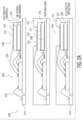
- FIG 8 shows one embodiment of a fourth electrochemical sensor 800 having a stacked configuration according to the invention.
- the fourth electrochemical sensor 800 is in a three dimensional (3D) configuration with two electrode layers.
- An electronic circuit with potentiostat, read-out, buffering, data processing, memory and communications circuitry, and an electrochemical cell are stacked together within a die 802.
- the die 802 includes a planarized passivation stack (not shown) on top.
- the passivation stack serves as barrier layer from an electrolyte filled porous layer within the electrochemical cell on top of the die 802. Additional layers (e.g. metal, platinum, silicon nitride) can be deposited on top of this passivation stack to augment the barrier layer.
- the die 802 includes the electronic circuit for the potentiostat and other electronics onto which a set of output electrodes 804 are patterned.
- a bottom electrode 808 is deposited and patterned on the die 802 and in contact with one of the set of output electrodes 804.
- the bottom electrode 808 in one example embodiment is a counter electrode, but in other embodiments could be either the working electrode or a reference electrode.
- a porous layer 810 is deposited and patterned on top of the bottom electrode 808 and in contact with another one of the set of output electrodes 804.
- a via 811 e.g. tungsten, preferably same material as top electrode otherwise risk of electrochemical reactions/corrosion
- a top electrode 812 is deposited and patterned on the porous layer 810 and in electrical contact with the via 811.
- the top electrode 812 in one example embodiment is a working electrode, but in other embodiments could be either a counter electrode or a reference electrode.
- the die 802 is connected to a lead frame 814 with bond wires 816.
- the die 802 is then encapsulated 817 (e.g. over molded) leaving an opening 818 over the electrochemical sensor's top electrode 812 in the die 802.
- the opening 818 permits the target gas to contact the top electrode 812 first during operation of the electrochemical sensor 800.
- the porous layer 810 is then partially or completely filled with an electrolyte.
- the electrolyte can in one example reach the porous layer 810 through the opening 818 and a via (not shown) in the top electrode 812. In another example, the electrolyte reaches the porous layer 810 through a separate via provided elsewhere in the encapsulated sensor 800 package.
- the porous layer 810 with electrolyte is shown as 820 in Fig. 8 .
- the porous layer can be porous enough so that the liquid electrolyte will penetrate through the electrode material film.
- the via 811 can be omitted by connecting the top electrode 812 to the lead frame 814 with a separate bond wire 816.
- FIG. 9 is a first example of a method 900 for manufacturing an electrochemical sensor for sensing a target substance.
- the method 900 begins in block 902, by fabricating a electrolyte matrix having a porous structure.
- block 904 coupling a working electrode to the electrolyte matrix at a first location is performed.
- block 906 coupling a counter electrode to the electrolyte matrix at a second location occurs.
- an electrolyte is added to the porous structure.
- an electrical circuit is coupled to the working electrode and the counter electrode, wherein the electrical circuit is capable of generating an output signal in response to an electrical current which flows between the working electrode and the counter electrode in response to a presence of the target substance. While the order in which these steps are implemented can be changed, the proposed sequence aims at manufacturing electrochemical cell first independently before connecting to read out electronics. Alternately steps 908 and 910 can be switched during wafer processing.
- Example embodiments of the material discussed in this specification can be implemented in whole or in part through network, computer, or data based devices and/or services. These may include cloud, internet, intranet, mobile, desktop, processor, look-up table, microcontroller, consumer equipment, infrastructure, or other enabling devices and services. As may be used herein and in the claims, the following non-exclusive definitions are provided.
- the method steps described above are implemented as functional and software instructions embodied as a set of executable instructions which are effected on a computer which is programmed with and controlled by said executable instructions. Such instructions are loaded for execution on a processor (such as one or more CPUs).
- the processor includes microprocessors, microcontrollers, processor modules or subsystems (including one or more microprocessors or microcontrollers), or other control or computing devices.
- a processor can refer to a single component or to plural components.
- one or more blocks or steps discussed herein are automated.
- apparatus, systems, and methods occur automatically.
- automated or automatically mean controlled operation of an apparatus, system, and/or process using computers and/or mechanical/electrical devices without the necessity of human intervention, observation, effort and/or decision.
- the methods illustrated herein and data and instructions associated therewith are stored in respective storage devices, which are implemented as one or more non-transient computer-readable or computer-usable storage media or mediums.
- the non-transient computer-usable media or mediums as defined herein excludes signals, but such media or mediums may be capable of receiving and processing information from signals and/or other transient mediums.
- the storage media include different forms of memory including semiconductor memory devices such as DRAM, or SRAM, Erasable and Programmable Read-Only Memories (EPROMs), Electrically Erasable and Programmable Read-Only Memories (EEPROMs) and flash memories; magnetic disks such as fixed, floppy and removable disks; other magnetic media including tape; and optical media such as Compact Disks (CDs) or Digital Versatile Disks (DVDs).
- semiconductor memory devices such as DRAM, or SRAM, Erasable and Programmable Read-Only Memories (EPROMs), Electrically Erasable and Programmable Read-Only Memories (EEPROMs) and flash memories
- magnetic disks such as fixed, floppy and removable disks
- other magnetic media including tape and optical media such as Compact Disks (CDs) or Digital Versatile Disks (DVDs).
- CDs Compact Disks
- DVDs Digital Versatile Disks
Description
- This specification relates generally to electrochemical sensors.
- Document
US 2003/0121781 A1 describes a hybrid film type sensor. A miniaturized gas sensor is designed for the detection of toxic gases such as carbon monoxide and comprises a nonconductive substrate, a reference electrode, a counter electrode and a working electrode. The gas sensor uses a Nafion electrolyte membrane. A gas or vapor sensing instrument includes a sensor cell assembly, a potential-control circuitry, a power supply and a microprocessor. -
DE 10323858 A1 refers to a sensor element and a sensor array. The sensor is designed for the detection of biomolecules such as DNA or proteins. A biosensor array may be realized for high-throughput-screening. Integrated circuits are fabricated on top or in a silicon substrate and comprise an electronic for a potentiostat. Interdigitated electrodes, a silicon nitride layer and a silicon oxide layer are formed over the integrated circuits. - Document
EP 0432757 A2 describes a planar oxygen sensor which comprises an insulating substrate, a cathode formed on the insulating substrate, another electrode formed on the insulating substrate, a gas permeable membrane stretched to cover these electrodes and an electrolytic solution between the gas permeable membrane and the insulating substrate. The sensor detects a gas, namely oxygen. The planar oxygen sensor is mounted in a region of a surface of a printed circuit board and a potentiostat circuit is mounted on another region of the surface of the printed circuit board. The planar oxygen sensor has a three-electrode structure, wherein the electrodes are connected to the potentiostat circuit by bonding wires. - Publication "Design and Fabrication of Complementary Metal-Oxide-Semiconductor Sensor Chip for Electrochemical Measurement", T. Yamazaki et al., shows an electrochemical measurement system with sensor electrodes, potentiostat and signal generator. The sensor is used to detect the hybridization of DNA inside a micro-fluidic sensor. Measurements which are performed by this measurement system detect the concentration of ferricyanide in a liquid.
- Publication "Digital Potentiostat for Electrochemical Bio Sensor Chips", A. Frey et al., describes a rail-to-rail potentiostat circuit suitable for CMOS-based electronic bio sensors. The bio sensor chips detect DNA. A cyclic voltammogram of ferrocene is performed with the bio sensor chips.
- It is an object of the present invention to provide an electrochemical sensor according to
independent claim 1 and a method for manufacturing an electrochemical sensor for sensing a target substance according to independent claim 13. - Further embodiments and developments are defined in the
dependent claims 2 to 12. - According to a first aspect, there is provided an electrochemical sensor for sensing a target substance, comprising: an electrolyte matrix, wherein the matrix reposits an electrolyte; a working electrode coupled to the electrolyte matrix at a first location; a counter electrode coupled to the electrolyte matrix at a second location; an electrical circuit, coupled to the working electrode and the counter electrode, and capable of generating an output signal in response to an electrical current which flows between the working electrode and the counter electrode in response to a presence of the target substance. The electrolyte matrix may be one from a group consisting of: a solid electrolyte and nafion. The electrolyte matrix may be a porous layer impregnated with a liquid electrolyte; and the porous layer may include at least one from a group consisting of: a porous inorganic material, Silicon Dioxide, Aluminum Oxide, a porous organic material, a polymer, a non- porous inorganic material having pores, a fibrous substrate, and a glass fiber meshwork. The electrolyte matrix may keep the electrodes in contact with the electrolyte irrespective of the electrochemical sensor's physical orientation. The electrical circuit includes a potentiostat coupled to the working and counter electrodes.
- The working electrode may be located between the target substance and a first side of the electrolyte matrix, and the counter electrode may be located between a substrate and a side opposite to the first side of the electrolyte matrix. The working electrode and the counter electrode may be located between the target substance and a first side of the electrolyte matrix.
- The target substance may contact the working electrode before contacting the counter electrode. The target substance may be at least one from a group consisting of: a gas, a liquid, a solid, a molecule, a chemical element, and a carbon compound. The substrate may include at least one from a group consisting of: silicon, silicon dioxide, nitride layer; glass; a polymer, a water proof compound, a chemically resistant compound.
- The sensor according to the present invention further comprises an electrochemical cell including the electrolyte matrix; wherein the electrical circuit includes a potentiostat; wherein the electrochemical cell and the potentiostat are co-integrated within a substrate; and wherein the substrate may be located on a first side of the potentiostat and the electrochemical cell may be located on a side opposite to the first side of the potentiostat circuit. The sensor may further comprise an electrochemical cell including the electrolyte matrix; an encapsulation encloses the electrical circuit and having an opening; wherein the opening is positioned above the electrochemical cell; and wherein the encapsulation includes a second opening positioned above an environmental sensor in the electrical circuit. The sensor may further comprising a filter proximate to the opening and blocking one or more non-target substances. The sensor may further comprise an electrolyte reservoir proximate to the electrolyte matrix and replenishing the electrolyte in the electrolyte matrix. The electrochemical cell and potentiostat may be fabricated using CMOS processes.
- There is also provided an electrochemical sensor for sensing a target substance, said sensor not forming part of the present invention and comprising: first and second electrolyte matrices having a porous structure, wherein the porous structure reposits an electrolyte; a middle electrode coupled between the first and second electrolyte matrices; a bottom electrode coupled to a side of the first electrolyte matrix opposite to the middle electrode; a top electrode coupled to a side of the second electrolyte matrix opposite to the middle electrode; an electrical circuit, coupled to the top, middle and bottom electrodes, and capable of generating an output signal in response to an electrical current which flows between any two of the electrodes in response to a presence of the target substance. The top electrode may be a working electrode, the middle electrode may be a counter electrode, and the bottom electrode may be a reference electrode; and wherein the electrical circuit may include a potentiostat coupled to the working, counter and reference electrodes.
- According to a further aspect, there is provided a method for manufacturing an electrochemical sensor for sensing a target substance, comprising: fabricating a electrolyte matrix having a porous structure; coupling a working electrode to the electrolyte matrix at a first location; coupling a counter electrode to the electrolyte matrix at a second location; adding an electrolyte to the porous structure; and coupling an electrical circuit to the working electrode and the counter electrode, wherein the electrical circuit is capable of generating an output signal in response to an electrical current which flows between the working electrode and the counter electrode in response to a presence of the target substance.
-
-
Figures 1A and1B show one example of a first electrochemical sensor, which is not according to the invention. -
Figures 2A and2B show one example of a second electrochemical sensor, which is not according to the invention. -
Figure 3 shows one example of the second electrochemical sensor having two middle electrodes. -
Figures 4A and4B show one example of a third electrochemical sensor, which is not according to the invention. -
Figure 5 shows one example of the first electrochemical sensor having an additional sensor. -
Figure 6 shows one example of the first electrochemical sensor having a filter. -
Figure 7 shows one example of the first electrochemical sensor having a reservoir. -
Figure 8 shows an embodiment of the first electrochemical sensor having a stacked configuration according to the present invention. -
Figure 9 is a first example of a method for manufacturing an electrochemical sensor. - While the disclosure is amenable to various modifications and alternative forms, specifics thereof have been shown by way of example in the drawings and will be described in detail. It should be understood, however, that other embodiments, beyond the particular embodiments described, are possible as well. All modifications, equivalents, and alternative embodiments falling within the scope of the appended claims are covered as well.
- Multiple example embodiments of an electrochemical sensor are provided forthwith. Electrochemical sensors detect target substances and in response generate an electrical signal. The example embodiments to follow are for electrochemical sensor's designed to sense a target gas, however the teaching provided applies equally to sensing target liquids, molecules, solids, chemical elements, and the like. In one example embodiment the electrochemical sensor is used for monitoring a carbon compound such as carbon monoxide (CO) in a residential or a public building.
- The electrochemical sensor includes an electrochemical cell portion and a potentiostat circuit. The electrochemical cell and the potentiostat circuit are coupled by a working electrode, a counter electrode and, depending on the required accuracy of the electrochemical cell, a reference electrode. These electrodes are coupled together by an electrolyte. In one example embodiment all electrodes + electrolyte = electrochemical cell.
- The working electrode responds to a target gas by either oxidizing or reducing the gas and thereby creating a current flow that is proportional to the gas's concentration. This current is supplied to the electrochemical cell through the counter electrode.
- The working electrode potential is maintained at the same potential as the reference electrode potential for unbiased electrochemical sensors, or with an offset potential for sensors that require biasing.
- The counter electrode completes a circuit with the working electrode, and reduces a chemical species (e.g. oxygen) if the working electrode is oxidizing, or oxidizes a chemical species if the working electrode is reducing the target gas. The potential of the counter electrode is allowed to float, sometimes changing as the gas concentration increases. If a reference electrode is included, the potential on the counter electrode is not important, so long as the potentiostat circuit can provide sufficient voltage and current to maintain the working electrode at the same potential as the reference electrode.
- The counter electrode is controlled by the potentiostat circuit such that the potential of the working electrode with respect to the potential of the reference electrode is kept constant. In case of two electrodes the counter electrode is controlled such that voltage between working electrode and counter electrode are kept constant.
- The electrochemical cell includes an opening through which the gas molecules enter and subsequently diffuse into the electrolyte and to the electrodes where they are reduced or oxidized by the voltage applied between the electrodes. In case of one example embodiment of an electrochemical CO sensor the following reactions take place at the electrodes:
- ∘ At sensing (working) electrode : CO + H2O → CO2 + 2H+ + 2e-
- ∘ At counter electrode : ½O2 + 2H+ + 2e- → H2O
- ∘ Overall reaction is: CO + ½O2 → CO2
- Three processes governing an equilibrium situation in one example embodiment of the electrochemical cell are:
- ∘ Absorption of the target chemical at the electrolyte interface;
- ∘ Transport of [CO] and [O2] by diffusion; and
- o Chemical molecules adsorbed at the electrode surface.
- This chemical reaction generates an electric current which is proportional to a number of reacting gas molecules entering the opening and thus the concentration of the gas can be calculated. The potentiostat controls the counter and measures the reference electrode potentials, measures the cell's currents and presents a read-out. Current within the potentiostat is limited by diffusion of CO molecules towards the electrodes. Below is an equation that allows for estimating the maximum current as a function of gas pressure:
- ∘

- o Where: "n" is the number of electrons involved in the reaction, F Faraday's constant, A the electrode surface area, DCO the diffusion constant of CO in the electrolyte, cCO the concentration of CO molecules at the air - electrolyte interface and δ the thickness of the electrolyte. DCO, kH and csolvent are material constants.
- In one example embodiment, the electrochemical cell and potentiostat are fabricated using CMOS processes. Using CMOS technology, currents of about 15 pA can be resolved. In an example where a minimal required sensing resolution is 5 ppm CO and entering the electrolytes are water and an ionic liquid (e.g. Bmim or NTf2), a minimal electrode surface area form factor (i.e. A(electrode)/δ(electrolyte)) for a 10 µm thick electrolyte is 0.16 to 1.1 mm2. Further form factor downscaling can be achieved by decreasing the electrolyte thickness.
- By using CMOS processes to fabricate the electrochemical sensor, both the electrochemical cell and potentiostat can be co-integrated within a single silicon die. This makes the electrochemical sensor very compact such that such electrochemical sensors can be ubiquitously incorporated into mobile devices such as cell phones and automotive vehicles. Such a compact form factor also decreases the risk of noise pick-up. While various example embodiments are presented below, features and manufacturing techniques of these example embodiments may be shared.
-
Figures 1A and1B show one example of a firstelectrochemical sensor 100, said sensor not being part of the present invention. The firstelectrochemical sensor 100 is in a three dimensional (3D) configuration with two electrode layers. An electrochemical cell is on afirst die 102 and a potentiostat circuit with other read-out, buffering, data processing, memory and communications circuitry is on asecond die 104. - The
first die 102 includes asubstrate 106. Thesubstrate 106 can take many forms such that electrolyte which will later added to thefirst die 102 will not corrode or short circuit any other circuitry in theelectrochemical sensor 100.Substrate 106 materials may include: a Si wafer with oxide or nitride layer; a glass plate; a polymer/plastic substrate, a water proof, chemically resistant adhesive compound. - A
bottom electrode 108 is deposited and patterned on thesubstrate 106 perhaps using screen printing or lift-off techniques. Thebottom electrode 108 is a counter electrode, but in other examples could be either the working electrode or include an additional reference electrode. - A
electrolyte matrix 110 is deposited and patterned on top of thebottom electrode 108. Theelectrolyte matrix 110 can be patterned with various techniques including: screen printing using polymers; inkjet printing using polymers or precursors for inorganic materials; blanket deposition and etch using a suitable mask needed; or sol gel deposition. Theelectrolyte matrix 110 could also be a fibrous substrate (e.g. of glass fiber meshwork which can contain and/or retain an electrolyte by capillary force). Theelectrolyte matrix 110 reposits (i.e. contains, stores up, includes, is a reservoir for, or soaks up) an electrolyte. - In one example, the
electrolyte matrix 110 is a solid electrolyte structure or membrane, such as nafion. In other examples, theelectrolyte matrix 110 is a porous layer impregnated with a liquid electrolyte and the porous layer is made from: a porous inorganic material (e.g. Silicon Dioxide (SiO2), Aluminum Oxide (Al2O3), etc.); a porous organic material (e.g. polymer); or a non- porous inorganic material (e.g. SiO2 with 'pores' etched into the layer after deposition). - A
top electrode 112 is deposited and patterned on theelectrolyte matrix 110 perhaps using screen printing or lift-off techniques. Thetop electrode 112 in one example is a working electrode, but in other examples could be either the counter electrode or include an additional reference electrode. - The working, counter and reference electrodes in one example are made of platinum, alternatively the reference electrode is made from Ag/AgCl. Other electrode metals may be used depending on the gas to be sensed and the chemical reactions involved. The electrodes can serve as catalyst and be chemically stable to discourage corrosion. While
Figs. 1A and1B show the top andbottom electrodes bottom electrode 108 may be replaced with a separate counter electrode and reference electrode which are electrically isolated but are still patterned on thesubstrate 106. Also, to increase the electrochemical sensor's 100 sensitivity, one or both of theelectrodes - The potentiostat and other circuitry formed on the
second die 104 is fabricated using standard CMOS techniques and connected to thefirst die 102 and alead frame 114 withbond wires 116. The first and second dies 102 and 104 are then encapsulated 117 (e.g. over molded) leaving anopening 118 over the electrochemical sensor'stop electrode 112 in thefirst die 102. The opening 118 permits the target gas to contact thetop electrode 112 first during operation of theelectrochemical sensor 100. - The
electrolyte matrix 110 is then partially or completely filled with an electrolyte. If theelectrolyte matrix 110 is a solid electrolyte, then additional electrolyte need not be added. The electrolyte can in one example reach theelectrolyte matrix 110 through theopening 118 and a via (not shown) in thetop electrode 112. In another example, the electrolyte reaches theelectrolyte matrix 110 through a separate via provided elsewhere in the encapsulatedsensor 100 package. The electrolyte can be applied by inkjet printing or micro drop which is gradually sucked up by theelectrolyte matrix 110. Theelectrolyte matrix 110 with a liquid electrolyte is shown as 120 inFig. 1A . - The
electrolyte matrix 110 thus functions as a reservoir for storing the electrochemical sensor's 100 electrolyte. Theelectrolyte matrix 110 acts like a sponge by having open pores which suck up and store the electrolyte. Since theelectrolyte matrix 110 acts like a scaffold for the electrolyte, theelectrolyte matrix 110 keeps thetop electrode 112 andbottom electrode 108 in a wetted condition irrespective of sensor orientation and environmental conditions (e.g. relative humidity) and thereby improves the electrochemical sensor's signal output stability and reduces the dependence of the sensor's signal output on environmental conditions. - The
electrolyte matrix 110 also keeps the electrolyte layer thickness proximate to the electrodes at a constant level as the sensor's 100 orientation changes. In order to discourage evaporation of electrolyte, the electrolyte can be an ionic liquid having a very low vapor pressure and thus little or no evaporation. - During operation of one example of the
first sensor 100 the working electrode is thetop electrode 112 and is in first contact with the target gas mixture entering theopening 118. Depending on the type of gas (e.g. CO or VOC) to be detected and measured, the gas may be electrochemically oxidized or reduced at the working electrode. In this example, thebottom electrode 108 includes the counter electrode and optionally the reference electrode. In this example, the counter and reference electrodes are mostly screened from direct contact with the target gas to be sensed and are instead in contact with products from the electrochemical reaction of the gas mixture at the working electrode. - A distance which the target gas and reaction products molecules have to diffuse to each electrode differs. The distance to the top working electrode is much less than the distance to the bottom counter and reference electrodes, thereby creating a potential difference between top and
bottom electrodes top electrode 112 is an anode, the oxidation of CO will no longer be transport controlled but will be reaction controlled. The local concentration ratio of CO/O2 determines the local electrode potential Emix. - While the following examples are discussed with reference to a porous layer, these examples equally apply to examples where the porous layer is an electrolyte matrix.
-
Figures 2A and2B show one example of a secondelectrochemical sensor 200, said sensor not forming part of the present invention. This example of the secondelectrochemical sensor 200 shares similarities with the firstelectrochemical sensor 100 so mainly the differences between the first andsecond sensors - An electrochemical cell is on a
first die 202 and a potentiostat circuit with other read-out, buffering, data processing, memory and communications circuitry is on asecond die 204. - The
first die 202 includes an insulatingsubstrate 206. Abottom electrode 208 is deposited and patterned on thesubstrate 206. Thebottom electrode 208 in one example is a reference electrode, but in other examples could alternatively be either the working electrode or include an additional reference electrode. - A first
porous layer 210 is deposited and patterned on top of thebottom electrode 208. - A
middle electrode 211 is deposited and patterned on the firstporous layer 210. Themiddle electrode 211 in one example is a counter electrode, but in other examples could be either the working electrode or reference electrode. - A second
porous layer 213 is deposited and patterned on top of themiddle electrode 211. - A
top electrode 212 is deposited and patterned on the secondporous layer 213. Thetop electrode 212 in one example is a working electrode, but in other examples could be either the counter electrode or the reference electrode. - While
Figs. 2A and2B show the top, middle andbottom electrodes bottom electrode 208 may be replaced with multiple electrodes or arranged in special shapes (e.g. meanders or rings). - The potentiostat and other circuitry formed on the
second die 204 is fabricated using standard CMOS techniques and connected to thefirst die 202 and alead frame 214 withbond wires 216. The first and second dies 202 and 204 are then encapsulated 217 (e.g. over molded) leaving anopening 218 over the electrochemical sensor'stop electrode 212 in thefirst die 202. The opening 218 permits the target gas to contact thetop electrode 212 first during operation of theelectrochemical sensor 200. - The first and second
porous layers porous layers opening 218 and vias (not shown) in the top andmiddle electrodes 212, 211 (also if the layers are porous and the electrodes are thin the electrolyte can just go through the electrodes; no separate VIA is needed; in case of the example with the separate reservoir the electrolyte can enter laterally / from the side). In another example, the electrolyte reaches theporous layers sensor 200 package. The electrolyte can be applied by inkjet printing or micro drop which is gradually sucked up by theporous layers porous layer 210 with electrolyte is shown as 220 inFig. 2A , and the secondporous layer 213 with electrolyte is shown as 222. -
Figure 3 shows one example of the secondelectrochemical sensor 200 having two middle electrodes, said sensor not forming part of the present invention. This second example of the secondelectrochemical sensor 200 shares similarities with the first example of the secondelectrochemical sensor 200. One difference is substitution of the singlemiddle electrode 211 with a firstmiddle electrode 302 and a secondmiddle electrode 304. In one example, thebottom electrode 208 is a first reference electrode, the firstmiddle electrode 302 is a counter electrode, the secondmiddle electrode 304 is a second reference electrode, and thetop electrode 212 is a working electrode. - Examples having these two reference electrodes can enable a higher accuracy electrochemical cell intended for detection of trace target gases at very low concentration.
- Other examples may have different top, first middle, second middle and bottom electrode circuit functions.
-
Figures 4A and4B show one example of a thirdelectrochemical sensor 400. The thirdelectrochemical sensor 400 is in a two dimensional (2D) configuration with one electrode layer. An electrochemical cell is on afirst die 402 and a potentiostat circuit with other read-out, buffering, data processing, memory and communications circuitry is on asecond die 404. - The
first die 402 includes an insulatingsubstrate 406. Aporous layer 410 is deposited and patterned on top of thesubstrate 406. A first, second and thirdtop electrode porous layer 410. In one example the firsttop electrode 412 is a counter electrode, the secondtop electrode 413 is a working electrode, and the thirdtop electrode 415 is a reference electrode. In other examples thesetop electrodes electrodes - The potentiostat and other circuitry formed on the
second die 404 is fabricated using standard CMOS techniques and connected to thefirst die 402 and alead frame 414 withbond wires 416. The first and second dies 402 and 404 are then encapsulated 417 (e.g. over molded) leaving anopening 418 over the electrochemical sensor'stop electrode 412 in thefirst die 402. The opening 418 permits the target gas to contact thetop electrodes electrochemical sensor 400. - The
porous layer 410 is then partially or completely filled with an electrolyte. The electrolyte can in one example reach theporous layer 410 through theopening 418 in thetop electrode 412. In another example, the electrolyte reaches theporous layer 410 through a separate via provided elsewhere in the encapsulatedsensor 400 package. Theporous layer 410 with electrolyte is shown as 420 inFig. 4A . - In this 2D electrode configuration, the electrodes are in a planar arrangement and all electrodes are exposed to the same gases through the
opening 418. A potential difference is applied between the electrodes to drive the reaction. With the electrodes on top, thesensor 400 current is not restricted by the electrolyte layer thickness and diffusion processes is governed by the much higher reaction rates for the reaction at the electrodes. In an alternate example (not shown),electrodes substrate 406 underneath theporous layer 410 and the target gas molecules must diffuse through the porous layer withelectrolyte 420 before reacting at theelectrodes -
Figure 5 shows one example of the firstelectrochemical sensor 100 having an additional sensor. As discussed for the firstelectrochemical sensor 100, thesecond die 102 includes the potentiostat and other circuitry; however, in this example, thesecond die 102 further includes additional sensing functionality such as a temperature sensor, a relative humidity sensor and/or other environmental sensors. The first and second dies 102 and 104 are then encapsulated 117 (e.g. over molded) leaving theopening 118 over the electrochemical sensor'stop electrode 112 in thefirst die 102, but also leaving asecond opening 502 over the additional sensing functionality in thesecond die 104. Theseopenings first die 102 and the additional sensing functionality in thesecond die 104 during operation of theelectrochemical sensor 100. The additional sensing functionality can be used to compensate for potential cross sensitivities of the electrochemical cell. Electrochemical cell may be sensitive e.g. to also relative humidity and temperature. In order to compensate for this effect a separate relative humidity sensor can be added. -
Figure 6 shows one example of the firstelectrochemical sensor 100 having afilter 602, said sensor not forming part of the present invention. Thefilter 602 is placed over theopening 118 which is above the electrochemical cell in thefirst die 102. In one example thefilter 602 improves the electrochemical sensor's 100 target chemical selectivity by blocking one or more non-target substances (e.g. a CO sensor could include a filter to oxidize ethanol vapors which could cause similar electrode currents as the CO to be detected). - The
filter 602 is fixed above theopening 118 with anchoring structures 604 (e.g. pins, rings, adhesives). The anchoringstructures 604 can be directly formed by and/or integrated into theencapsulation 117.Individual filter 602 layers can be cut with a punch tool, applied by a pick and place machine, and glued or ultrasonically welded to the anchoringstructures 604. Thefilter 602 may also serve to protect the electrochemical cell in thefirst die 102 from contaminants and reduce evaporation of the electrolyte from theelectrolyte matrix 110. Afilter 602 which minimizes evaporation includes a semi permeable membrane that allows passage of e.g. CO but not H2O. -
Figure 7 shows one example of the firstelectrochemical sensor 100 having a reservoir. This example is similar to the embodiment shown inFigs. 1A and1B except that, in thefirst die 102, thesubstrate 106 and theelectrolyte matrix 110 have be extended in a lateral direction while the top andbottom electrodes - The first and second dies 102 and 104 are then encapsulated 117 leaving the
opening 118 over the electrochemical sensor'stop electrode 112 and adding asecond opening 702 over theelectrolyte matrix 110. Theelectrolyte matrix 110 is then partially or completely filled with anelectrolyte 704. Theelectrolyte 704 is also is added into thesecond opening 702, thereby forming a reservoir of theelectrolyte 704. This reservoir of electrolyte further buffers potential evaporation or uptake of water by theelectrolyte matrix 110. Acover 706 can be added over thesecond opening 702 to further counteract any effects of evaporation on theelectrolyte 704 in the reservoir. -
Figure 8 shows one embodiment of a fourthelectrochemical sensor 800 having a stacked configuration according to the invention. The fourthelectrochemical sensor 800 is in a three dimensional (3D) configuration with two electrode layers. An electronic circuit with potentiostat, read-out, buffering, data processing, memory and communications circuitry, and an electrochemical cell are stacked together within adie 802. - The
die 802 includes a planarized passivation stack (not shown) on top. The passivation stack serves as barrier layer from an electrolyte filled porous layer within the electrochemical cell on top of thedie 802. Additional layers (e.g. metal, platinum, silicon nitride) can be deposited on top of this passivation stack to augment the barrier layer. - The
die 802 includes the electronic circuit for the potentiostat and other electronics onto which a set ofoutput electrodes 804 are patterned. Abottom electrode 808 is deposited and patterned on thedie 802 and in contact with one of the set ofoutput electrodes 804. Thebottom electrode 808 in one example embodiment is a counter electrode, but in other embodiments could be either the working electrode or a reference electrode. - A
porous layer 810 is deposited and patterned on top of thebottom electrode 808 and in contact with another one of the set ofoutput electrodes 804. A via 811 (e.g. tungsten, preferably same material as top electrode otherwise risk of electrochemical reactions/corrosion) is created through theporous layer 810 and is electrically connected to another one of the set ofoutput electrodes 804. - A
top electrode 812 is deposited and patterned on theporous layer 810 and in electrical contact with the via 811. Thetop electrode 812 in one example embodiment is a working electrode, but in other embodiments could be either a counter electrode or a reference electrode. - The
die 802 is connected to alead frame 814 withbond wires 816. Thedie 802 is then encapsulated 817 (e.g. over molded) leaving anopening 818 over the electrochemical sensor'stop electrode 812 in thedie 802. The opening 818 permits the target gas to contact thetop electrode 812 first during operation of theelectrochemical sensor 800. - The
porous layer 810 is then partially or completely filled with an electrolyte. The electrolyte can in one example reach theporous layer 810 through theopening 818 and a via (not shown) in thetop electrode 812. In another example, the electrolyte reaches theporous layer 810 through a separate via provided elsewhere in the encapsulatedsensor 800 package. Theporous layer 810 with electrolyte is shown as 820 inFig. 8 . However, the porous layer can be porous enough so that the liquid electrolyte will penetrate through the electrode material film. - In an alternate example, the via 811 can be omitted by connecting the
top electrode 812 to thelead frame 814 with aseparate bond wire 816. -
Figure 9 is a first example of a method 900 for manufacturing an electrochemical sensor for sensing a target substance. The method 900 begins in block 902, by fabricating a electrolyte matrix having a porous structure. Next, inblock 904, coupling a working electrode to the electrolyte matrix at a first location is performed. Inblock 906, coupling a counter electrode to the electrolyte matrix at a second location occurs. In block 908 an electrolyte is added to the porous structure. Then inblock 910, an electrical circuit is coupled to the working electrode and the counter electrode, wherein the electrical circuit is capable of generating an output signal in response to an electrical current which flows between the working electrode and the counter electrode in response to a presence of the target substance. While the order in which these steps are implemented can be changed, the proposed sequence aims at manufacturing electrochemical cell first independently before connecting to read out electronics. Alternately steps 908 and 910 can be switched during wafer processing. - The blocks comprising the flowcharts in the above Figures can be effected in any order, unless a specific order is explicitly stated. Also, those skilled in the art will recognize that while one example method embodiment is now discussed, the material in this specification can be combined in a variety of ways to yield other examples as well. The method next discussed is to be understood within a context provided by this and other portions of this detailed description.
- Example embodiments of the material discussed in this specification can be implemented in whole or in part through network, computer, or data based devices and/or services. These may include cloud, internet, intranet, mobile, desktop, processor, look-up table, microcontroller, consumer equipment, infrastructure, or other enabling devices and services. As may be used herein and in the claims, the following non-exclusive definitions are provided.
- In some example embodiments the method steps described above are implemented as functional and software instructions embodied as a set of executable instructions which are effected on a computer which is programmed with and controlled by said executable instructions. Such instructions are loaded for execution on a processor (such as one or more CPUs). The processor includes microprocessors, microcontrollers, processor modules or subsystems (including one or more microprocessors or microcontrollers), or other control or computing devices. A processor can refer to a single component or to plural components.
- In one example, one or more blocks or steps discussed herein are automated. In other words, apparatus, systems, and methods occur automatically. The terms automated or automatically (and like variations thereof) mean controlled operation of an apparatus, system, and/or process using computers and/or mechanical/electrical devices without the necessity of human intervention, observation, effort and/or decision.
- In some examples, the methods illustrated herein and data and instructions associated therewith are stored in respective storage devices, which are implemented as one or more non-transient computer-readable or computer-usable storage media or mediums. The non-transient computer-usable media or mediums as defined herein excludes signals, but such media or mediums may be capable of receiving and processing information from signals and/or other transient mediums. The storage media include different forms of memory including semiconductor memory devices such as DRAM, or SRAM, Erasable and Programmable Read-Only Memories (EPROMs), Electrically Erasable and Programmable Read-Only Memories (EEPROMs) and flash memories; magnetic disks such as fixed, floppy and removable disks; other magnetic media including tape; and optical media such as Compact Disks (CDs) or Digital Versatile Disks (DVDs). Note that the instructions of the software discussed above can be provided on one computer-readable or computer-usable storage medium, or alternatively, can be provided on multiple computer-readable or computer-usable storage media distributed in a large system having possibly plural nodes. Such computer-readable or computer-usable storage medium or media is (are) considered to be part of an article (or article of manufacture). An article or article of manufacture can refer to any manufactured single component or multiple components.
Claims (13)
- An electrochemical gas sensor, comprising:- an electrochemical cell including an electrolyte matrix (810), wherein the matrix (810) reposits an electrolyte; a working electrode (808, 812) coupled to the electrolyte matrix (810) at a first location; and a counter electrode (812, 808) coupled to the electrolyte matrix (810) at a second location; and- an electrical circuit which includes a potentiostat, is coupled to the working electrode (808, 812) and the counter electrode (812, 808), and is configured to generate an output signal in response to an electrical current which flows between the working electrode (808, 812) and the counter electrode (812, 808) in response to a presence of a target substance,characterized in
that both the electrochemical cell and the potentiostat are co-integrated within a single silicon die (802); wherein the electrochemical sensor (800) has a stacked configuration, wherein the electrical circuit with the potentiostat and the electrochemical cell are stacked together within the silicon die (802). - The sensor of claim 1, wherein the electrolyte matrix (810) is one from a group consisting of: a solid electrolyte and nafion.
- The sensor of claim 1, wherein:the electrolyte matrix (810) is a porous layer impregnated with a liquid electrolyte; andthe porous layer includes at least one from a group consisting of: a porous inorganic material, silicon dioxide, aluminum oxide, a porous organic material, a polymer, a non-porous inorganic material having pores, a fibrous substrate, and a glass fiber meshwork.
- The sensor of claim 1, wherein the electrolyte matrix (810) keeps the electrodes (808, 812) in contact with the electrolyte irrespective of the electrochemical sensor's physical orientation.
- The sensor of claim 1, wherein the potentiostat is coupled to the working and counter electrodes (808, 812).
- The sensor of claim 1, wherein the working electrode (812) is located between the target substance and a first side of the electrolyte matrix (810), and the counter electrode (808) is located between a substrate and a side opposite to the first side of the electrolyte matrix (810).
- The sensor of claim 1, wherein the working electrode (808, 812) and the counter electrode (812, 808) are located between the target substance and a first side of the electrolyte matrix (810).
- The sensor of claim 1, wherein the target substance contacts the working electrode (812) before contacting the counter electrode (808).
- The sensor of claim 1, wherein the substrate includes at least one from a group consisting of: silicon, silicon dioxide, nitride layer; glass; a polymer, a water proof compound, a chemically resistant compound.
- The sensor of claim 1,further comprising an encapsulation (817) enclosing the electrical circuit and having an opening (818);wherein the opening (818) is positioned above the electrochemical cell; andwherein the encapsulation (817) includes a second opening (502) positioned above an environmental sensor in the electrical circuit.
- The sensor of claim 1, further comprising a filter proximate to the opening (818) and blocking one or more non-target substances.
- The sensor of claim 1, further comprising an electrolyte reservoir proximate to the electrolyte matrix (810) and replenishing the electrolyte in the electrolyte matrix (810).
- A method for manufacturing an electrochemical gas sensor, comprising:fabricating an electrolyte matrix (810) having a porous structure;coupling a working electrode (808, 812) to the electrolyte matrix (810) at a first location;coupling a counter electrode (812, 808) to the electrolyte matrix (810) at a second location;adding an electrolyte to the porous structure; andcoupling an electrical circuit to the working electrode (808, 812) and the counter electrode (812, 808), wherein the electrical circuit includes a potentiostat and is configured to generate an output signal in response to an electrical current which flows between the working electrode (808, 812) and the counter electrode (812, 808) in response to a presence of a target substance; andwherein the electrochemical sensor (800) comprises an electrochemical cell including the electrolyte matrix (810), the working electrode (808, 812) and the counter electrode (812, 808),characterized inthat both the electrochemical cell and the potentiostat are co-integrated within a single silicon die (802); wherein the electrochemical sensor (800) has a stacked configuration, wherein the electrical circuit with the potentiostat and the electrochemical cell are stacked together within the silicon die (802).
Applications Claiming Priority (1)
| Application Number | Priority Date | Filing Date | Title |
|---|---|---|---|
| US14/192,648 US9513247B2 (en) | 2014-02-27 | 2014-02-27 | Electrochemical sensor |
Publications (2)
| Publication Number | Publication Date |
|---|---|
| EP2913667A1 EP2913667A1 (en) | 2015-09-02 |
| EP2913667B1 true EP2913667B1 (en) | 2023-03-01 |
Family
ID=52347194
Family Applications (1)
| Application Number | Title | Priority Date | Filing Date |
|---|---|---|---|
| EP15151261.3A Active EP2913667B1 (en) | 2014-02-27 | 2015-01-15 | Electrochemical sensor |
Country Status (3)
| Country | Link |
|---|---|
| US (1) | US9513247B2 (en) |
| EP (1) | EP2913667B1 (en) |
| CN (1) | CN104880499B (en) |
Families Citing this family (9)
| Publication number | Priority date | Publication date | Assignee | Title |
|---|---|---|---|---|
| WO2017123205A1 (en) * | 2016-01-12 | 2017-07-20 | Honeywell International Inc. | Electrochemical sensor |
| US20170336343A1 (en) * | 2016-05-19 | 2017-11-23 | InSyte Systems | Integrated sensing device for detecting gasses |
| EP3346267B1 (en) * | 2017-01-10 | 2021-09-01 | Sensirion AG | Sensor device for detecting a permanent gas |
| US10756745B2 (en) | 2017-01-27 | 2020-08-25 | Verily Life Sciences Llc | Electrical circuit for biasing or measuring current from a sensor |
| US10732141B2 (en) | 2017-02-15 | 2020-08-04 | InSyte Systems | Electrochemical gas sensor system with improved accuracy and speed |
| US11567031B2 (en) * | 2017-09-08 | 2023-01-31 | Oakland University | Selective real-time gas sensing |
| US11054383B2 (en) | 2018-01-22 | 2021-07-06 | InSyte Systems, Inc. | Chip-scale sensing device for low density material |
| JP7201178B2 (en) * | 2019-06-13 | 2023-01-10 | 日本航空電子工業株式会社 | Electrochemical measurement method for catalytic reaction product, electrochemical measurement device, and transducer |
| CN110530952B (en) * | 2019-08-19 | 2022-05-17 | 广州钰芯传感科技有限公司 | Card-inserting type electrochemical gas sensor module and packaging method thereof |
Family Cites Families (22)
| Publication number | Priority date | Publication date | Assignee | Title |
|---|---|---|---|---|
| US3616416A (en) | 1969-07-02 | 1971-10-26 | Hydronautics | Oxygen detector for analysis of oxygen in gaseous streams including an internal humidifier |
| US4536274A (en) | 1983-04-18 | 1985-08-20 | Diamond Shamrock Chemicals Company | pH and CO2 sensing device and method of making the same |
| WO1989001148A1 (en) | 1987-07-28 | 1989-02-09 | Daikin Industries, Ltd. | Combustible gas sensor |
| CH678660A5 (en) | 1988-02-24 | 1991-10-15 | Matsushita Electric Works Ltd | |
| JPH03183943A (en) * | 1989-12-14 | 1991-08-09 | Hitachi Ltd | Oxygen sensor |
| JPH04348280A (en) | 1991-05-24 | 1992-12-03 | Honda Motor Co Ltd | Heater built-in hybrid ic |
| US5387329A (en) | 1993-04-09 | 1995-02-07 | Ciba Corning Diagnostics Corp. | Extended use planar sensors |
| GB9625464D0 (en) * | 1996-12-07 | 1997-01-22 | Central Research Lab Ltd | Gas sensor |
| US6936147B2 (en) * | 1999-11-19 | 2005-08-30 | Perkinelmer Las, Inc. | Hybrid film type sensor |
| CA2417149C (en) * | 2000-07-27 | 2009-09-08 | City Technology Limited | Gas sensors |
| JP2002174618A (en) | 2000-12-07 | 2002-06-21 | Matsushita Electric Ind Co Ltd | Solid electrolyte gas sensor |
| DE10323858A1 (en) | 2003-05-26 | 2004-12-30 | Infineon Technologies Ag | Biosensor to detect particles in an analyte, e.g. for high throughput screening, has a substrate with surface electrodes and a gold compartmenting unit to take the catch molecules |
| US20080128285A1 (en) | 2006-12-04 | 2008-06-05 | Electronics And Telecommunications Research Institute | Electrochemical gas sensor chip and method of manufacturing the same |
| GB0704972D0 (en) | 2007-03-15 | 2007-04-25 | Varney Mark S | Neoteric room temperature ionic liquid gas sensor |
| KR101640103B1 (en) | 2008-12-01 | 2016-07-15 | 엠에스에이 유럽 게엠베하 | Electrochemical gas sensors with ionic liquid electrolyte systems |
| DE102008044240B4 (en) | 2008-12-01 | 2013-12-05 | Msa Auer Gmbh | Electrochemical gas sensor with an ionic liquid as the electrolyte, which contains at least one mono-, di- or trialkylammonium cation |
| EP2241882A1 (en) | 2009-04-15 | 2010-10-20 | Neroxis SA | Amperometric electrochemical sensor and manufacturing method |
| AR073963A1 (en) | 2009-10-23 | 2010-12-15 | Comision Nac De En Atomica | INTEGRATED ELECTRONIC DEVICE WITH SENSITIVE COATING FOR THE DETECTION OF BIOLOGICAL GASES OR MOLECULES AND METHOD OF MANUFACTURING OF THE SAME |
| US9125625B2 (en) | 2010-06-10 | 2015-09-08 | The Regents Of The University Of California | Textile-based printable electrodes for electrochemical sensing |
| US8852513B1 (en) | 2011-09-30 | 2014-10-07 | Silicon Laboratories Inc. | Systems and methods for packaging integrated circuit gas sensor systems |
| CA2851804C (en) * | 2011-10-14 | 2018-03-20 | Mine Safety Appliances Company | Method for testing a gas sensor |
| EP2759832B1 (en) | 2013-01-23 | 2020-11-11 | Sciosense B.V. | Electrochemical sensor device |
-
2014
- 2014-02-27 US US14/192,648 patent/US9513247B2/en active Active
-
2015
- 2015-01-15 EP EP15151261.3A patent/EP2913667B1/en active Active
- 2015-02-15 CN CN201510082174.1A patent/CN104880499B/en active Active
Non-Patent Citations (1)
| Title |
|---|
| FREY A ET AL: "Digital potentiostat for electrochemical bio sensor chips", ESSCIRC, 2010 PROCEEDINGS OF THE, IEEE, PISCATAWAY, NJ, USA, 14 September 2010 (2010-09-14), pages 390 - 393, XP031788390, ISBN: 978-1-4244-6662-7 * |
Also Published As
| Publication number | Publication date |
|---|---|
| EP2913667A1 (en) | 2015-09-02 |
| US20150241375A1 (en) | 2015-08-27 |
| US9513247B2 (en) | 2016-12-06 |
| CN104880499A (en) | 2015-09-02 |
| CN104880499B (en) | 2017-12-12 |
Similar Documents
| Publication | Publication Date | Title |
|---|---|---|
| EP2913667B1 (en) | Electrochemical sensor | |
| US4874500A (en) | Microelectrochemical sensor and sensor array | |
| US8266795B2 (en) | Methods of making an electrochemical gas sensor | |
| US8535499B2 (en) | Microfabricated liquid-junction reference electrode | |
| US10620151B2 (en) | Electrochemical sensor, and a method of forming an electrochemical sensor | |
| US8784640B2 (en) | Amperometric electrochemical sensor and method for manufacturing same | |
| US10895548B2 (en) | Reference electrode with a pore membrane | |
| US20050072690A1 (en) | Ion exchange membranes and dissolved gas sensors | |
| CN103940862B (en) | Electrochemical sensor device | |
| US20110212376A1 (en) | Amperometric sensor | |
| US8999127B2 (en) | Biological sensor measuring electrochemical and/or electrical and diamond electrode and electronic integrated circuit | |
| JP2014528590A (en) | Sensor and sensor manufacturing method | |
| US11592416B2 (en) | Electrochemical sensor with opening between solid elements | |
| WO2004038397A1 (en) | Analytical tool | |
| EP2827141B1 (en) | Device and method for electrochemical gas sensing | |
| US20080116083A1 (en) | Electrochemical gas sensor with at least one punctiform measuring electrode | |
| US11846598B2 (en) | Reference electrode | |
| JP2009002802A (en) | Water sensor and dew condensation sensor | |
| US20030087453A1 (en) | Method and device for producing and screening composite arrangements | |
| CN114829918A (en) | Sensor with solid layered structure and method for manufacturing the same | |
| US8901433B2 (en) | Individually addressable band electrode arrays and methods to prepare the same | |
| JPH04225154A (en) | Electrochemical gas sensor element |
Legal Events
| Date | Code | Title | Description |
|---|---|---|---|
| PUAI | Public reference made under article 153(3) epc to a published international application that has entered the european phase |
Free format text: ORIGINAL CODE: 0009012 |
|
| AK | Designated contracting states |
Kind code of ref document: A1 Designated state(s): AL AT BE BG CH CY CZ DE DK EE ES FI FR GB GR HR HU IE IS IT LI LT LU LV MC MK MT NL NO PL PT RO RS SE SI SK SM TR |
|
| AX | Request for extension of the european patent |
Extension state: BA ME |
|
| RAP1 | Party data changed (applicant data changed or rights of an application transferred) |
Owner name: AMS INTERNATIONAL AG |
|
| 17P | Request for examination filed |
Effective date: 20160302 |
|
| RBV | Designated contracting states (corrected) |
Designated state(s): AL AT BE BG CH CY CZ DE DK EE ES FI FR GB GR HR HU IE IS IT LI LT LU LV MC MK MT NL NO PL PT RO RS SE SI SK SM TR |
|
| STAA | Information on the status of an ep patent application or granted ep patent |
Free format text: STATUS: EXAMINATION IS IN PROGRESS |
|
| 17Q | First examination report despatched |
Effective date: 20191204 |
|
| STAA | Information on the status of an ep patent application or granted ep patent |
Free format text: STATUS: EXAMINATION IS IN PROGRESS |
|
| RAP1 | Party data changed (applicant data changed or rights of an application transferred) |
Owner name: SCIOSENSE B.V. |
|
| REG | Reference to a national code |
Ref country code: DE Ref legal event code: R079 Ref document number: 602015082622 Country of ref document: DE Free format text: PREVIOUS MAIN CLASS: G01N0027403000 Ipc: G01N0027404000 |
|
| GRAP | Despatch of communication of intention to grant a patent |
Free format text: ORIGINAL CODE: EPIDOSNIGR1 |
|
| STAA | Information on the status of an ep patent application or granted ep patent |
Free format text: STATUS: GRANT OF PATENT IS INTENDED |
|
| RIC1 | Information provided on ipc code assigned before grant |
Ipc: G01N 27/407 20060101ALN20220914BHEP Ipc: G01N 33/00 20060101ALI20220914BHEP Ipc: G01N 27/404 20060101AFI20220914BHEP |
|
| RIC1 | Information provided on ipc code assigned before grant |
Ipc: G01N 27/407 20060101ALN20220916BHEP Ipc: G01N 33/00 20060101ALI20220916BHEP Ipc: G01N 27/404 20060101AFI20220916BHEP |
|
| INTG | Intention to grant announced |
Effective date: 20221004 |
|
| GRAS | Grant fee paid |
Free format text: ORIGINAL CODE: EPIDOSNIGR3 |
|
| GRAA | (expected) grant |
Free format text: ORIGINAL CODE: 0009210 |
|
| STAA | Information on the status of an ep patent application or granted ep patent |
Free format text: STATUS: THE PATENT HAS BEEN GRANTED |
|
| AK | Designated contracting states |
Kind code of ref document: B1 Designated state(s): AL AT BE BG CH CY CZ DE DK EE ES FI FR GB GR HR HU IE IS IT LI LT LU LV MC MK MT NL NO PL PT RO RS SE SI SK SM TR |
|
| REG | Reference to a national code |
Ref country code: GB Ref legal event code: FG4D |
|
| REG | Reference to a national code |
Ref country code: CH Ref legal event code: EP Ref country code: AT Ref legal event code: REF Ref document number: 1551308 Country of ref document: AT Kind code of ref document: T Effective date: 20230315 |
|
| REG | Reference to a national code |
Ref country code: DE Ref legal event code: R096 Ref document number: 602015082622 Country of ref document: DE |
|
| REG | Reference to a national code |
Ref country code: IE Ref legal event code: FG4D |
|
| P01 | Opt-out of the competence of the unified patent court (upc) registered |
Effective date: 20230515 |
|
| REG | Reference to a national code |
Ref country code: LT Ref legal event code: MG9D |
|
| REG | Reference to a national code |
Ref country code: NL Ref legal event code: MP Effective date: 20230301 |
|
| PG25 | Lapsed in a contracting state [announced via postgrant information from national office to epo] |
Ref country code: RS Free format text: LAPSE BECAUSE OF FAILURE TO SUBMIT A TRANSLATION OF THE DESCRIPTION OR TO PAY THE FEE WITHIN THE PRESCRIBED TIME-LIMIT Effective date: 20230301 Ref country code: NO Free format text: LAPSE BECAUSE OF FAILURE TO SUBMIT A TRANSLATION OF THE DESCRIPTION OR TO PAY THE FEE WITHIN THE PRESCRIBED TIME-LIMIT Effective date: 20230601 Ref country code: LV Free format text: LAPSE BECAUSE OF FAILURE TO SUBMIT A TRANSLATION OF THE DESCRIPTION OR TO PAY THE FEE WITHIN THE PRESCRIBED TIME-LIMIT Effective date: 20230301 Ref country code: LT Free format text: LAPSE BECAUSE OF FAILURE TO SUBMIT A TRANSLATION OF THE DESCRIPTION OR TO PAY THE FEE WITHIN THE PRESCRIBED TIME-LIMIT Effective date: 20230301 Ref country code: HR Free format text: LAPSE BECAUSE OF FAILURE TO SUBMIT A TRANSLATION OF THE DESCRIPTION OR TO PAY THE FEE WITHIN THE PRESCRIBED TIME-LIMIT Effective date: 20230301 Ref country code: ES Free format text: LAPSE BECAUSE OF FAILURE TO SUBMIT A TRANSLATION OF THE DESCRIPTION OR TO PAY THE FEE WITHIN THE PRESCRIBED TIME-LIMIT Effective date: 20230301 |
|
| REG | Reference to a national code |
Ref country code: AT Ref legal event code: MK05 Ref document number: 1551308 Country of ref document: AT Kind code of ref document: T Effective date: 20230301 |
|
| PG25 | Lapsed in a contracting state [announced via postgrant information from national office to epo] |
Ref country code: SE Free format text: LAPSE BECAUSE OF FAILURE TO SUBMIT A TRANSLATION OF THE DESCRIPTION OR TO PAY THE FEE WITHIN THE PRESCRIBED TIME-LIMIT Effective date: 20230301 Ref country code: PL Free format text: LAPSE BECAUSE OF FAILURE TO SUBMIT A TRANSLATION OF THE DESCRIPTION OR TO PAY THE FEE WITHIN THE PRESCRIBED TIME-LIMIT Effective date: 20230301 Ref country code: NL Free format text: LAPSE BECAUSE OF FAILURE TO SUBMIT A TRANSLATION OF THE DESCRIPTION OR TO PAY THE FEE WITHIN THE PRESCRIBED TIME-LIMIT Effective date: 20230301 Ref country code: GR Free format text: LAPSE BECAUSE OF FAILURE TO SUBMIT A TRANSLATION OF THE DESCRIPTION OR TO PAY THE FEE WITHIN THE PRESCRIBED TIME-LIMIT Effective date: 20230602 Ref country code: FI Free format text: LAPSE BECAUSE OF FAILURE TO SUBMIT A TRANSLATION OF THE DESCRIPTION OR TO PAY THE FEE WITHIN THE PRESCRIBED TIME-LIMIT Effective date: 20230301 |
|
| PG25 | Lapsed in a contracting state [announced via postgrant information from national office to epo] |
Ref country code: SM Free format text: LAPSE BECAUSE OF FAILURE TO SUBMIT A TRANSLATION OF THE DESCRIPTION OR TO PAY THE FEE WITHIN THE PRESCRIBED TIME-LIMIT Effective date: 20230301 Ref country code: RO Free format text: LAPSE BECAUSE OF FAILURE TO SUBMIT A TRANSLATION OF THE DESCRIPTION OR TO PAY THE FEE WITHIN THE PRESCRIBED TIME-LIMIT Effective date: 20230301 Ref country code: PT Free format text: LAPSE BECAUSE OF FAILURE TO SUBMIT A TRANSLATION OF THE DESCRIPTION OR TO PAY THE FEE WITHIN THE PRESCRIBED TIME-LIMIT Effective date: 20230703 Ref country code: EE Free format text: LAPSE BECAUSE OF FAILURE TO SUBMIT A TRANSLATION OF THE DESCRIPTION OR TO PAY THE FEE WITHIN THE PRESCRIBED TIME-LIMIT Effective date: 20230301 Ref country code: CZ Free format text: LAPSE BECAUSE OF FAILURE TO SUBMIT A TRANSLATION OF THE DESCRIPTION OR TO PAY THE FEE WITHIN THE PRESCRIBED TIME-LIMIT Effective date: 20230301 Ref country code: AT Free format text: LAPSE BECAUSE OF FAILURE TO SUBMIT A TRANSLATION OF THE DESCRIPTION OR TO PAY THE FEE WITHIN THE PRESCRIBED TIME-LIMIT Effective date: 20230301 |
|
| PG25 | Lapsed in a contracting state [announced via postgrant information from national office to epo] |
Ref country code: SK Free format text: LAPSE BECAUSE OF FAILURE TO SUBMIT A TRANSLATION OF THE DESCRIPTION OR TO PAY THE FEE WITHIN THE PRESCRIBED TIME-LIMIT Effective date: 20230301 Ref country code: IS Free format text: LAPSE BECAUSE OF FAILURE TO SUBMIT A TRANSLATION OF THE DESCRIPTION OR TO PAY THE FEE WITHIN THE PRESCRIBED TIME-LIMIT Effective date: 20230701 |
|
| REG | Reference to a national code |
Ref country code: DE Ref legal event code: R097 Ref document number: 602015082622 Country of ref document: DE |
|
| PLBE | No opposition filed within time limit |
Free format text: ORIGINAL CODE: 0009261 |
|
| STAA | Information on the status of an ep patent application or granted ep patent |
Free format text: STATUS: NO OPPOSITION FILED WITHIN TIME LIMIT |
|
| PG25 | Lapsed in a contracting state [announced via postgrant information from national office to epo] |
Ref country code: SI Free format text: LAPSE BECAUSE OF FAILURE TO SUBMIT A TRANSLATION OF THE DESCRIPTION OR TO PAY THE FEE WITHIN THE PRESCRIBED TIME-LIMIT Effective date: 20230301 Ref country code: DK Free format text: LAPSE BECAUSE OF FAILURE TO SUBMIT A TRANSLATION OF THE DESCRIPTION OR TO PAY THE FEE WITHIN THE PRESCRIBED TIME-LIMIT Effective date: 20230301 |
|
| 26N | No opposition filed |
Effective date: 20231204 |