WO2022168278A1 - 空調機システム - Google Patents
空調機システム Download PDFInfo
- Publication number
- WO2022168278A1 WO2022168278A1 PCT/JP2021/004397 JP2021004397W WO2022168278A1 WO 2022168278 A1 WO2022168278 A1 WO 2022168278A1 JP 2021004397 W JP2021004397 W JP 2021004397W WO 2022168278 A1 WO2022168278 A1 WO 2022168278A1
- Authority
- WO
- WIPO (PCT)
- Prior art keywords
- unit
- information
- indoor
- identification information
- indoor unit
- Prior art date
Links
- 238000004891 communication Methods 0.000 claims abstract description 185
- 238000004378 air conditioning Methods 0.000 claims description 10
- 238000010977 unit operation Methods 0.000 claims 1
- 238000012545 processing Methods 0.000 description 19
- 238000000034 method Methods 0.000 description 17
- 238000010586 diagram Methods 0.000 description 15
- 238000001514 detection method Methods 0.000 description 14
- 238000001816 cooling Methods 0.000 description 8
- 230000006870 function Effects 0.000 description 7
- 238000010438 heat treatment Methods 0.000 description 5
- 238000012544 monitoring process Methods 0.000 description 5
- 238000005516 engineering process Methods 0.000 description 3
- 230000010354 integration Effects 0.000 description 3
- 230000005540 biological transmission Effects 0.000 description 2
- 238000007664 blowing Methods 0.000 description 2
- 238000013461 design Methods 0.000 description 1
- 230000002093 peripheral effect Effects 0.000 description 1
- 230000004044 response Effects 0.000 description 1
- 239000004065 semiconductor Substances 0.000 description 1
- 238000009423 ventilation Methods 0.000 description 1
Images


Classifications
-
- F—MECHANICAL ENGINEERING; LIGHTING; HEATING; WEAPONS; BLASTING
- F24—HEATING; RANGES; VENTILATING
- F24F—AIR-CONDITIONING; AIR-HUMIDIFICATION; VENTILATION; USE OF AIR CURRENTS FOR SCREENING
- F24F11/00—Control or safety arrangements
- F24F11/50—Control or safety arrangements characterised by user interfaces or communication
- F24F11/54—Control or safety arrangements characterised by user interfaces or communication using one central controller connected to several sub-controllers
-
- F—MECHANICAL ENGINEERING; LIGHTING; HEATING; WEAPONS; BLASTING
- F24—HEATING; RANGES; VENTILATING
- F24F—AIR-CONDITIONING; AIR-HUMIDIFICATION; VENTILATION; USE OF AIR CURRENTS FOR SCREENING
- F24F11/00—Control or safety arrangements
- F24F11/62—Control or safety arrangements characterised by the type of control or by internal processing, e.g. using fuzzy logic, adaptive control or estimation of values
- F24F11/63—Electronic processing
-
- F—MECHANICAL ENGINEERING; LIGHTING; HEATING; WEAPONS; BLASTING
- F24—HEATING; RANGES; VENTILATING
- F24F—AIR-CONDITIONING; AIR-HUMIDIFICATION; VENTILATION; USE OF AIR CURRENTS FOR SCREENING
- F24F11/00—Control or safety arrangements
- F24F11/50—Control or safety arrangements characterised by user interfaces or communication
- F24F11/56—Remote control
-
- F—MECHANICAL ENGINEERING; LIGHTING; HEATING; WEAPONS; BLASTING
- F24—HEATING; RANGES; VENTILATING
- F24F—AIR-CONDITIONING; AIR-HUMIDIFICATION; VENTILATION; USE OF AIR CURRENTS FOR SCREENING
- F24F11/00—Control or safety arrangements
- F24F11/62—Control or safety arrangements characterised by the type of control or by internal processing, e.g. using fuzzy logic, adaptive control or estimation of values
-
- F—MECHANICAL ENGINEERING; LIGHTING; HEATING; WEAPONS; BLASTING
- F24—HEATING; RANGES; VENTILATING
- F24F—AIR-CONDITIONING; AIR-HUMIDIFICATION; VENTILATION; USE OF AIR CURRENTS FOR SCREENING
- F24F11/00—Control or safety arrangements
- F24F11/30—Control or safety arrangements for purposes related to the operation of the system, e.g. for safety or monitoring
- F24F11/49—Control or safety arrangements for purposes related to the operation of the system, e.g. for safety or monitoring ensuring correct operation, e.g. by trial operation or configuration checks
-
- F—MECHANICAL ENGINEERING; LIGHTING; HEATING; WEAPONS; BLASTING
- F24—HEATING; RANGES; VENTILATING
- F24F—AIR-CONDITIONING; AIR-HUMIDIFICATION; VENTILATION; USE OF AIR CURRENTS FOR SCREENING
- F24F3/00—Air-conditioning systems in which conditioned primary air is supplied from one or more central stations to distributing units in the rooms or spaces where it may receive secondary treatment; Apparatus specially designed for such systems
- F24F3/06—Air-conditioning systems in which conditioned primary air is supplied from one or more central stations to distributing units in the rooms or spaces where it may receive secondary treatment; Apparatus specially designed for such systems characterised by the arrangements for the supply of heat-exchange fluid for the subsequent treatment of primary air in the room units
- F24F3/065—Air-conditioning systems in which conditioned primary air is supplied from one or more central stations to distributing units in the rooms or spaces where it may receive secondary treatment; Apparatus specially designed for such systems characterised by the arrangements for the supply of heat-exchange fluid for the subsequent treatment of primary air in the room units with a plurality of evaporators or condensers
Definitions
- the present disclosure relates to an air conditioner system.
- air conditioner In an air conditioner (hereinafter referred to as "air conditioner") system in which multiple indoor units are connected to one outdoor unit, using an external server or an external operation terminal, operation of the indoor unit and the outdoor unit
- a communication unit for example, a network adapter
- a communication unit for example, a network adapter
- Patent Document 1 requires a communication unit for each device, which complicates communication processing and increases cost.
- Patent Document 2 although it is not necessary to provide a communication unit for each indoor unit, information on each of the plurality of outdoor units and the plurality of indoor units is sent via one communication unit. Therefore, in order to collectively manage the information of each device, the user needs to register each device using an external terminal or the like. Moreover, even if each device is registered, the user cannot easily know which indoor unit is connected to which outdoor unit.
- the present disclosure has been made in view of the above circumstances, and in an air conditioner system in which a plurality of indoor units are connected to one outdoor unit, it is possible to easily collectively manage each device with a simple configuration.
- One of the objects is to provide an air conditioner system.
- An air conditioner system comprising: a communication unit that performs communication between any one of the outdoor unit and the plurality of indoor units and an external device; and a communication control unit that associates the first identification information set in the communication unit with the second identification information set uniquely to the communication unit and transmits the information to the external device via the communication unit.
- an air conditioner system in which a plurality of indoor units are connected to one outdoor unit can easily collectively manage each device with a simple configuration.
- FIG. 1 is a system diagram showing an example of an air conditioner system according to a first embodiment
- FIG. FIG. 2 is a block diagram showing an example of configurations of an outdoor unit, an indoor unit, and an antenna unit according to the first embodiment
- 4 is a sequence diagram showing an example of initialization processing according to the first embodiment
- FIG. FIG. 5 is a sequence diagram showing the flow of operating state monitoring processing according to the first embodiment
- 4 is a sequence diagram showing the flow of driving operation instruction processing according to the first embodiment
- FIG. The system diagram which shows an example of the air conditioner system which concerns on 2nd Embodiment.
- FIG. 1 is a system diagram showing an example of an air conditioner system according to this embodiment.
- the air conditioner system 1 is a multi-type air conditioner (air conditioner) system in which a plurality of indoor units 20 are connected to one outdoor unit 10 .
- the illustrated air conditioner system 1 includes one outdoor unit 10 installed outside the building, three indoor units 20 (20a, 20b, 20c) installed inside the building, an antenna unit 30, A remote controller 40 (40a, 40b, 40c) corresponding to each of the three indoor units 20 is provided.
- one outdoor unit 10 is installed for each floor, one indoor unit 20 is installed for each room on each floor, and a plurality of (here, three) indoor units 20 are installed. are connected to one outdoor unit 10 installed on the same floor.
- the remote controller 40 is a remote controller that communicates with the indoor unit 20 using infrared rays.
- the remote controller 40 outputs an operation instruction signal including operation details to be instructed to the indoor unit 20 by infrared rays.
- the operation contents instructed to the indoor unit 20 include, for example, operations to start and stop operation, operations to switch between cooling operation, heating operation, and air blowing operation, operations to set the set temperature, operations to set the air volume, and the like. is.
- the indoor unit 20 receives the operation instruction signal output from the remote controller 40 and controls the operation based on the operation content included in the received operation instruction signal.
- remote controllers 40a, 40b, and 40c are remote controllers for operating indoor units 20a, 20b, and 20c, respectively. Note that the remote controller 40 and the indoor unit 20 may communicate via a communication line.
- the antenna unit 30 is connected to the indoor unit 20a.
- the antenna unit 30 is an example of a communication unit for communicating between the indoor unit 20 a and the external operation terminal 60 via the repeater 50 .
- the antenna unit 30 is communication equipment including an antenna for connecting to a LAN (Local Area Network) provided in a building by wireless communication.
- the repeater 50 is, for example, a wireless LAN router that communicates and connects a public line such as the Internet or a mobile phone communication network with a LAN in a building.
- the indoor unit 20a and the external operation terminal 60 can communicate with each other by connecting to the wireless LAN via the repeater 50.
- the external operation terminal 60 is, for example, a terminal operated by a user, such as a smart phone or a tablet terminal.
- the external operation terminal 60 acquires information possessed by each device of the outdoor unit 10 and the indoor unit 20 and collectively manages the information.
- the information possessed by each device of the outdoor unit 10 and the indoor unit 20 is, for example, information regarding the operating state of each device.
- the information about the operating state includes information indicating the operating state such as operating or stopped, information indicating the operating mode such as cooling, heating, or fan, setting information such as set temperature and air volume, room temperature, outside temperature, or internal temperature. Detection information such as temperature is included.
- the external operation terminal 60 acquires information about the operating state from each device at regular intervals and displays the operating state of each device.
- the external operation terminal 60 acquires information about the operating state of each device from the indoor unit 20a to which the antenna unit 30 is connected via the repeater 50.
- unique identification information is set for each of the outdoor unit 10, the indoor unit 20, and the antenna unit 30.
- the identification information of the antenna unit 30 is set to "ID31".
- the indoor unit 20a associates identification information uniquely set to each of the outdoor unit 10 and the indoor unit 20 with identification information uniquely set to the antenna unit 30, and performs external operation via the antenna unit 30 and the repeater 50.
- a control unit 230 for transmitting to the terminal 60 is provided.
- the control unit 230 associates information about the operating state of the indoor unit 20a with “ID22” and “ID31” and transmits the information to the external operation terminal 60 .
- the control unit 230 associates information about the operating state of the indoor unit 20b with "ID22” and acquires it via the communication line 101 and the outdoor unit 10, and associates the acquired information about the operating state with "ID22” and "ID31". It associates and transmits to the external operation terminal 60 .
- control unit 230 associates the information about the operating state of the indoor unit 20c with "ID23” and acquires it via the communication line 101 and the outdoor unit 10, and associates the acquired information about the operating state with "ID23” and “ID31”. It associates and transmits to the external operation terminal 60 . Further, the control unit 230 associates information about the operating state of the outdoor unit 10 with "ID11” and acquires it via the communication line 101, associates the acquired information about the operating state with "ID11” and "ID31", and associates the information about the operating state with "ID11” and "ID31”. Send to terminal 60 . As a result, the external operation terminal 60 communicates with only the indoor unit 20a, thereby acquiring and monitoring information regarding the operating state of each of the outdoor unit 10 and the plurality of indoor units 20 in a distinguishable manner for each device. can do.
- the external operation terminal 60 can be connected to the indoor unit 20a for communication from outside the building.
- the repeater 50 includes a communication base station for public lines in addition to the wireless LAN router.
- the external operation terminal 60 can collectively manage the outdoor unit 10 and the plurality of indoor units 20 from outside the building as well as within a range in which communication can be connected to the LAN inside the building.
- the external management server 70 can communicate with the indoor unit 20a via the repeater 50.
- the external management server 70 may be a cloud server. By communicating only with the indoor unit 20a, the external management server 70 can acquire and monitor information about the operating state of each of the outdoor unit 10 and the plurality of indoor units 20 so that each device can be distinguished. can.
- FIG. 2 is a block diagram showing an example of configurations of the outdoor unit 10, the indoor unit 20, and the antenna unit 30 according to this embodiment.
- the communication control unit 131 controls communication with each of the indoor units 20a, 20b, and 20c via the wired communication unit 110 and the communication line 101. For example, the communication control unit 131 acquires information about the operating state of each of the indoor units 20a, 20b, and 20c from each of the indoor units 20a, 20b, and 20c. For example, the communication control unit 131 acquires information in which identification information is associated with information regarding the operating state of each of the indoor units 20a, 20b, and 20c, and stores the information in the storage unit 120. FIG. Specifically, the communication control unit 131 periodically acquires information in which the information about the operating state and the identification information are associated with each other, and stores the information in the storage unit 120 .
- the communication control unit 131 may acquire information in which identification information is associated with at least information regarding the operating state of each of the indoor units 20b and 20c, and store the information in the storage unit 120. Then, the communication control unit 131 may transmit to the indoor unit 20a information in which the identification information is associated with the information regarding the operation state of each of the indoor units 20b and 20c stored in the storage unit 120.
- the operation control unit 132 controls the operation of the outdoor unit 10. For example, the operation control unit 132 controls the operation of the outdoor unit 10 based on the information about the operating state of each of the indoor units 20a, 20b, 20c acquired from each of the indoor units 20a, 20b, 20c. Specifically, the operation control unit 132 controls operations of the compressor 141, the outdoor unit fan 143, and the like.
- the indoor unit 20 (20a) includes a wired communication unit 210, a storage unit 220, an indoor unit control unit 230, an indoor unit fan 241, a heat exchanger 242, a flap 243, an internal temperature sensor 244, and a room temperature sensor. 245.
- the wired communication unit 210 includes a communication device for communicating with the outdoor unit 10.
- the wired communication unit 210 is connected to the outdoor unit 10 via the communication line 101 .
- the wired communication unit 210 of the indoor unit 20 a is further connected to the antenna unit 30 via the communication line 102 and communicates with the antenna unit 30 as well.
- a control program for controlling the operation of the indoor unit 20 and the like are stored in the storage unit 220 .
- the storage unit 220 stores identification information of the indoor unit 20 and information on the operating state.
- the storage unit 220 of the indoor unit 20a stores identification information ("ID21") of the indoor unit 20a and information on the operating state. Further, in the storage unit 220 of the indoor unit 20a, the identification information (“ID11”) of the outdoor unit 10 acquired from the outdoor unit 10, information on the operating state, and other indoor units acquired through the outdoor unit 10 The identification information (“ID22”, “ID23”) of 20b and 20c and information on the operating state are stored.
- the storage unit 220 of the indoor unit 20b stores identification information (“ID22”) of the indoor unit 20b and information about the operating state, identification information (“ID11”) of the outdoor unit 10 and information about the operating state, and other information.
- the identification information (“ID21”, “ID23”) of the indoor units 20a and 20c and information on the operating state are stored.
- the storage unit 220 of the indoor unit 20c stores identification information (“ID23”) of the indoor unit 20c and information about the operating state, identification information (“ID11”) of the outdoor unit 10 and information about the operating state, and other indoor units.
- the identification information (“ID21”, “ID22”) of 20a and 20b and information on the operating state are stored. That is, the identification information and operating state information of the outdoor unit 10 and the identification information and operating state information of each indoor unit 20 are stored in the storage unit 120 of the outdoor unit 10 and the storage unit 220 of the indoor unit 20, respectively. shared.
- the indoor unit controller 230 corresponds to the controller 230 shown in FIG.
- the indoor unit control section 230 controls each section of the indoor unit 20 .
- the indoor unit controller 230 includes a CPU, memory, and the like.
- the indoor unit control unit 230 includes a communication control unit 231 , an operation control unit 232 and a state detection unit 233 as functional configurations realized by executing the control program stored in the storage unit 220 .
- the communication control unit 231 controls communication with the outdoor unit 10 via the wired communication unit 210 and the communication line 101.
- the communication control unit 231 of the indoor unit 20a associates information about the operating state of the indoor unit 20a with identification information (“ID21”) and transmits the information to the outdoor unit 10 .
- the communication control unit 231 of the indoor unit 20b associates the information about the operating state of the indoor unit 20b with the identification information (“ID22”) and transmits them to the outdoor unit 10 .
- the communication control unit 231 of the indoor unit 20c associates information about the operating state of the indoor unit 20c with identification information (“ID23”) and transmits the information to the outdoor unit 10 .
- the communication control unit 231 of the indoor unit 20a acquires from the outdoor unit 10 information in which identification information is associated with information on the operating state of each of the other indoor units 20b and 20c. Further, the communication control unit 231 acquires from the outdoor unit 10 information in which the information about the operating state of the outdoor unit 10 and the identification information are associated with each other. The communication control unit 231 causes the storage unit 220 to store each information acquired from the outdoor unit 10 .
- the communication control unit 231 of the indoor unit 20a associates the information possessed by each of the outdoor unit 10 and the indoor units 20a, 20b, and 20c with the identification information of each device and the identification information of the antenna unit 30, and operates the antenna unit 30. to the external operation terminal 60 via the
- FIG. 3 is a diagram showing an example of information transmitted to the external operation terminal 60 by the indoor unit 20a according to this embodiment.
- An example of information to be transmitted to the external operation terminal 60 shown in this figure is information for the external operation terminal 60 to monitor the operation status of the outdoor unit 10 and the indoor unit 20, and is related to identification information and operation status of each device. Information is associated information.
- the information in which the identification information of each device and the information about the operating state are associated is hereinafter referred to as "operating state information".
- the communication control unit 231 of the indoor unit 20a uses the identification information (“ID31”) of the antenna unit 30, the identification information (“ID11”) of the outdoor unit 10, and the outdoor unit 10 as the operating state information of the outdoor unit 10. (during operation, internal temperature, outside temperature, . Further, the communication control unit 231 of the indoor unit 20a uses the identification information (“ID31”) of the antenna unit 30, the identification information (“ID21”) of the indoor unit 20a, and the indoor unit 20a as the operating state information of the indoor unit 20a. (during operation, cooling, set temperature, internal temperature, room temperature, .
- the communication control unit 231 of the indoor unit 20a uses the identification information (“ID31”) of the antenna unit 30, the identification information (“ID22”) of the indoor unit 20b, and the indoor unit 20b as the operating state information of the indoor unit 20b. (during operation, cooling, set temperature, internal temperature, room temperature, . Further, the communication control unit 231 of the indoor unit 20a uses the identification information (“ID31”) of the antenna unit 30, the identification information (“ID23”) of the indoor unit 20c, and the indoor unit 20c as the operating state information of the indoor unit 20c. (during operation, cooling, set temperature, internal temperature, room temperature, .
- the communication control unit 231 acquires operation instruction information indicating operation instructions for each of the indoor units 20a, 20b, and 20c from the external operation terminal 60 via the antenna unit 30.
- the operation instruction information is associated with identification information of the indoor unit 20 to be operated, identification information of the antenna unit 30, and information indicating operation details.
- the operation content refers to operation of the indoor unit 20, such as an operation to start operation, an operation to stop operation, an operation to switch between cooling operation, heating operation, and fan operation, an operation to set a set temperature, an operation to set air volume, and the like. Content.
- FIG. 4 is a diagram showing an example of operation instruction information according to this embodiment.
- the communication control unit 231 of the indoor unit 20a receives the identification information (“ID31”) of the antenna unit 30 and the identification information (“ID21”) of the indoor unit 20a. ”) and the operation content for the indoor unit 20 a are acquired from the external operation terminal 60 via the antenna unit 30 .
- the communication control unit 231 of the indoor unit 20a receives the identification information (“ID31”) of the antenna unit 30 and the identification information (“ID22”) of the indoor unit 20b.
- the communication control unit 231 of the indoor unit 20a receives the identification information (“ID31”) of the antenna unit 30 and the identification information (“ID23”) of the indoor unit 20c. ”) and the operation content for the indoor unit 20 c are acquired from the external operation terminal 60 via the antenna unit 30 .
- the communication control unit 231 of the indoor unit 20a transmits the acquired operation identification information to each of the indoor units 20b and 20c via the outdoor unit 10.
- the operation control unit 232 controls the operation of the indoor unit 20. Specifically, the operation control unit 132 of each indoor unit 20 controls the indoor unit fan 241 and the flap 243 provided in each indoor unit 20, and the like. For example, upon receiving an operation instruction signal output from the remote controller 40a, the operation control unit 232 of the indoor unit 20a controls the operation of the indoor unit 20a based on the operation content included in the received operation instruction signal. Upon receiving the operation instruction signal output from the remote controller 40b, the operation control unit 232 of the indoor unit 20b controls the operation of the indoor unit 20b based on the operation content included in the received operation instruction signal. Upon receiving the operation instruction signal output from the remote controller 40c, the operation control unit 232 of the indoor unit 20c controls the operation of the indoor unit 20c based on the operation content included in the received operation instruction signal.
- the operation control unit 232 of the indoor unit 20c obtains the information included in the operation instruction information.
- the operation of the indoor unit 20c is controlled based on the operation content received. That is, each of the indoor units 20 operates based on the operation content included in the operation instruction information when it is the operation target according to the identification information of the indoor unit 20 included in the operation instruction information acquired by the communication control unit 231. Control.
- the state detection section 233 detects the state of each section of the indoor unit 20 .
- the state detection unit 233 detects the operation state of the indoor unit 20 controlled by the operation control unit 232 (operating, stopped, set temperature, etc.) at regular intervals.
- the state detection unit 233 detects the internal temperature and the room temperature at regular intervals based on the sensor outputs of the internal temperature sensor 244 and the room temperature sensor 245 .
- the internal temperature sensor 244 is a temperature sensor provided inside the indoor unit 20 to detect the temperature inside the indoor unit 20 .
- internal temperature sensor 244 detects the temperature of heat exchanger 242 or the like.
- a room temperature sensor 245 is a temperature sensor provided in the indoor unit 20 to detect the room temperature.
- the state detection unit 233 stores the detected operating state, internal temperature, room temperature, etc. in the storage unit 220 as information regarding the operating state.
- the wired communication unit 310 includes a communication device for communicating with either one of the outdoor unit 10 or the indoor unit 20.
- the wired communication unit 310 is connected to the indoor unit 20a via the communication line 102, and communicates with the indoor unit 20a.
- the wireless communication unit 320 includes a communication device for performing wireless communication with the repeater 50.
- repeater 50 is a wireless LAN router.
- the wireless communication unit 320 includes a communication device such as an antenna for connecting with the repeater 50 via a wireless LAN.
- the storage unit 330 stores identification information ("ID31") of the antenna unit 30, a control program for controlling the operation of the antenna unit 30, and the like.
- the communication control unit 340 includes a CPU, memory, and the like. Communication control section 340 controls each section of antenna unit 30 by executing a control program stored in storage section 330 . Specifically, the communication control unit 340 controls communication with the indoor unit 20 a via the wired communication unit 310 . Also, the communication control unit 340 controls communication with the repeater 50 via the wireless communication unit 320 .
- the communication control unit 340 negotiates the communication speed and communication method, and transmits the information of the antenna unit 30 to the indoor unit 20a via the wired communication unit 310. , receives information of the indoor unit 20a from the indoor unit 20a via the wired communication unit 310.
- the communication control unit 340 transmits the identification information (“ID31”) of the antenna unit 30 to the indoor unit 20a.
- the communication control unit 340 also receives the identification information (“ID21”) of the indoor unit 20a from the indoor unit 20a.
- the communication control unit 340 After communication is established by negotiation, the communication control unit 340 acquires various information transmitted from the indoor unit 20a via the wired communication unit 310, and transmits the acquired various information to the repeater 50 via the wireless communication unit 320. Send. Further, the communication control unit 340 acquires various information transmitted from the repeater 50 via the wireless communication unit 320, and transmits the acquired various information to the indoor unit 20a via the wired communication unit 310.
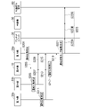
- FIG. 5 is a sequence diagram showing an example of initialization processing according to this embodiment.
- Step S101 When the antenna unit 30 is connected to the indoor unit 20a, the antenna unit 30 and the indoor unit 20a perform communication negotiation processing. In the negotiation process, the antenna unit 30 transmits identification information (“ID31”) of the antenna unit 30 to the indoor unit 20a. The indoor unit 20a acquires and stores the identification information (“ID31”) of the antenna unit 30 transmitted from the antenna unit 30 .
- ID31 identification information
- Step S105 The indoor unit 20b transmits the identification information (“ID22”) of the indoor unit 20b to the outdoor unit 10.
- the outdoor unit 10 acquires the identification information (“ID22”) of the indoor unit 20 b transmitted from the indoor unit 20 b and stores it in the storage unit 220 .
- Step S109 The outdoor unit 10 stores the identification information (“ID21”) of the indoor unit 20a, the identification information (“ID22”) of the indoor unit 20b, and the identification information (“ID23”) of the indoor unit 20c.
- identification information (“ID11”) of the air conditioner system 1 and grouped as a group of identification information of the devices included in the air conditioner system 1 .
- the outdoor unit 10 transmits the grouped identification information group to the indoor unit 20a.
- the indoor unit 20a acquires the identification information group transmitted from the outdoor unit 10 and stores it in the storage unit 220 of the indoor unit 20a.
- Step S111 The indoor unit 20a associates the identification information group (“ID11”, “ID21”, “ID22”, “ID23”) acquired from the outdoor unit 10 with the identification information (“ID31”) of the antenna unit 30. Send to the external operation terminal 60 .
- ID31 the identification information group of the equipment provided in this air conditioner system 1 and the identification information group of the equipment provided in the other air conditioner system.
- the identification information group data transmitted from the indoor unit 20a to the external operation terminal 60 is first transmitted from the indoor unit 20a to the antenna unit 30 (step S111A), and then transmitted from the antenna unit 30 to the repeater 50 (step S111B). ), and is transmitted from the repeater 50 to the external operation terminal 60 (step S111C).
- the external operation terminal 60 can identify the devices provided in the air conditioner system 1 using the identification information of each device.
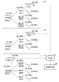
- FIG. 6 is a sequence diagram showing the flow of the operating state monitoring process according to this embodiment.
- Step S201 The indoor unit 20a detects information about the operating state of the indoor unit 20a, associates the detected information about the operating state with the identification information (“ID21”) of the indoor unit 20a, and stores the information in the storage unit 220 of the indoor unit 20a. Save to
- Step S203 The indoor unit 20a transmits to the outdoor unit 10 information in which the information about the operating state and the identification information ("ID21") are associated.
- the outdoor unit 10 acquires the information in which the information about the operating state transmitted from the indoor unit 20 a and the identification information “ID21”) are associated with each other, and stores the acquired information in the storage unit 120 .
- Step S205 The indoor unit 20b detects information about the operating state of the indoor unit 20b, associates the detected information about the operating state with the identification information (“ID22”) of the indoor unit 20b, and stores the information in the storage unit 220 of the indoor unit 20b. Save to
- Step S209 The outdoor unit 10 transmits to the indoor unit 20a information in which the information about the operating state acquired from the indoor unit 20b and the identification information "ID22") are associated.
- the indoor unit 20a stores information in which the information about the operating state of the indoor unit 20b transmitted from the outdoor unit 10 and the identification information "ID22") are associated in the storage unit 220 of the indoor unit 20a.
- the indoor unit 20c detects information about the operating state of the indoor unit 20c, associates the detected information about the operating state with the identification information (“ID23”) of the indoor unit 20c, and stores the information in the storage unit 220 of the indoor unit 20c. Save to
- Step S213 The indoor unit 20c transmits to the outdoor unit 10 information in which the information about the operating state and the identification information ("ID23") are associated.
- the outdoor unit 10 acquires the information in which the information about the operating state transmitted from the indoor unit 20c and the identification information “ID23”) are associated with each other, and stores the acquired information in the storage unit 120 .
- Step S215) The outdoor unit 10 transmits to the indoor unit 20a information in which the information about the operating state acquired from the indoor unit 20c and the identification information "ID23") are associated.
- the indoor unit 20a stores information in which the information about the operating state of the indoor unit 20c transmitted from the outdoor unit 10 and the identification information "ID23") are associated in the storage unit 220 of the indoor unit 20a.
- Step S21-7 The outdoor unit 10 detects information about the operating state of the outdoor unit 10, associates the detected operating state information with the identification information ("ID11") of the outdoor unit 10, and stores them in the storage unit 120.
- Step S219) The outdoor unit 10 transmits to the indoor unit 20a information in which the information about the operating state and the identification information ("ID11") of the outdoor unit 10 are associated.
- the indoor unit 20a stores information in which the information about the operating state of the outdoor unit 10 transmitted from the outdoor unit 10 and the identification information "ID11") are associated in the storage unit 220 of the indoor unit 20a.
- the indoor unit 20a obtains the operating state information (see FIG. 3) of the outdoor unit 10 in which the identification information (“ID31”) of the antenna unit 30 is associated with the information on the operating state of the outdoor unit 10 and the identification information (“ID11”). ).
- the indoor unit 20a generates the operating state information (see FIG. 3) of the indoor unit 20a in which the identification information (“ID31”) of the antenna unit 30 is associated with the information on the operating state of the indoor unit 20a and the identification information (“ID21”).
- the indoor unit 20a generates operating state information (see FIG. 3) of the indoor unit 20b in which the identification information (“ID31”) of the antenna unit 30 is associated with the information and identification information “ID22” regarding the operating state of the indoor unit 20b.
- the indoor unit 20a generates operating state information (see FIG. 3) of the indoor unit 20c in which the identification information (“ID31”) of the antenna unit 30 is associated with the information and identification information “ID23” regarding the operating state of the indoor unit 20c. .
- the indoor unit 20a transmits the operating state information of the outdoor unit 10, the operating state information of the indoor unit 20a, the operating state information of the indoor unit 20b, and the operating state information of the indoor unit 20c to the external operation terminal 60.
- Each operating state information transmitted from the indoor unit 20a to the external operation terminal 60 is first transmitted from the indoor unit 20a to the antenna unit 30 (step S223A), and then transmitted from the antenna unit 30 to the repeater 50 (step S223B). , and is transmitted from the repeater 50 to the external operation terminal 60 (step S223C).
- the external operation terminal 60 can monitor the operating state of each device provided in the air conditioner system 1 .
- step S201 to step S223 is repeatedly executed at a predetermined cycle. Further, the order of processing in which the outdoor unit 10 and each indoor unit 20 detect and transmit the operating state may be changed. Further, the process of detecting and transmitting the operating state of each of the outdoor unit 10 and each of the indoor units 20 may be performed in synchronization with a specific cycle.
- the external operation terminal 60 accepts a user's operation on the indoor unit 20 to be operated by the air conditioner system 1.
- the external operation terminal 60 displays an operation screen for accepting operation operations of the indoor units 20a, 20b, and 20c, and accepts user operations on the operation screen.
- this operation screen for each of the indoor unit 20a, the indoor unit 20b, and the indoor unit 20c, operations to start and stop operation, operations to switch between cooling operation, heating operation, and air blowing operation, operations to set the set temperature, and air volume Receives operation contents such as an operation to set
- Step S303 The external operation terminal 60 generates operation instruction information based on the user's operation received in step S301.
- the operation instruction information is associated with the identification information of the antenna unit 30 for specifying the air conditioner system 1 to be operated, the identification information of the indoor unit 20 to be operated, and the operation content (FIG. 4). reference). It should be noted that the external operation terminal 60 may generate operation instruction information according to an operation plan in which an operation target, operation content, and time are preset.
- Step S307 When the indoor unit 20a receives the operation instruction information transmitted from the external operation terminal 60, if the operation instruction information includes the formula heat information ("ID31") of the antenna unit 30, the operation instruction information to the outdoor unit 10. Also, in this case, the indoor unit 20a proceeds to the process of step S313.
- Steps S309, S311) Upon receiving the operation instruction information transmitted from the indoor unit 20a, the outdoor unit 10 transmits the operation instruction information to the indoor units 20b and 20c.
- the order of transmission to the indoor unit 20b and the indoor unit 20c may be either first or at the same time.
- Step S313 Based on the identification information of the indoor unit 20 included in the operation instruction information transmitted from the external operation terminal 60, the indoor unit 20a determines whether or not it is an operation target.
- the identification information of the indoor unit 20 included in the operation instruction information is the identification information (“ID21”) of the indoor unit 20a
- the indoor unit 20a determines that the indoor unit 20a is the operation target, and proceeds to the process of step S315.
- the identification information of the indoor unit 20 included in the operation instruction information is not the identification information (“ID21”) of the indoor unit 20a
- the indoor unit 20a determines that the indoor unit 20a is not an operation target, and performs the process of step S315. do not have.
- Step S317) Based on the identification information of the indoor unit 20 included in the operation instruction information transmitted from the external operation terminal 60, the indoor unit 20b determines whether it is an operation target.
- the identification information of the indoor unit 20 included in the operation instruction information is the identification information (“ID22”) of the indoor unit 20b
- the indoor unit 20b determines that the indoor unit 20b is the operation target, and proceeds to the process of step S319.
- the identification information of the indoor unit 20 included in the operation instruction information is not the identification information (“ID22”) of the indoor unit 20b
- the indoor unit 20b determines that the indoor unit 20b is not an operation target, and performs the processing of step S319. do not have.
- Step S319) When the indoor unit 20b is the operation target of the operation instruction information transmitted from the external operation terminal 60, the operation is controlled based on the operation instruction information. Specifically, the indoor unit 20b performs control according to the operation content included in the operation instruction information.
- Step S323 When the indoor unit 20c is the operation target of the operation instruction information transmitted from the external operation terminal 60, the operation is controlled based on the operation instruction information. Specifically, the indoor unit 20c performs control according to the operation content included in the operation instruction information.
- the air conditioner system 1 includes an antenna unit 30 (an example of a communication section) and a communication control section 231 .
- the antenna unit 30 communicates with one of the outdoor unit 10 and the plurality of indoor units 20 and an external operation terminal 60 (an example of an external device).
- the communication control unit 231 controls identification information (first identification information) uniquely set to each of the plurality of indoor units 20 of the outdoor unit 10 and identification information uniquely set to the antenna unit 30 (second identification information). are associated with each other and transmitted to the external operation terminal 60 (an example of an external device) via the antenna unit 30 .
- the air conditioner system 1 can specify the information of the air conditioner system 1 and each device using the identification information of the antenna unit 30 and the identification information of each device of the outdoor unit 10 and the plurality of indoor units 20. With a simple configuration, it is possible to collectively manage the information of each device easily from an external device (for example, the external operation terminal 60).
- the communication control unit 231 associates the identification information (first identification information) of the indoor unit 20 to be operated among the plurality of indoor units 20 and the operation content with the identification information (second identification information) of the antenna unit 30.
- the received operation instruction information is acquired from the external operation terminal 60 via the antenna unit 30 .
- An operation control unit 232 is provided to control the operation.
- the communication method described above is an example, and any communication method can be applied.
- the communication is performed using Bluetooth (registered trademark) or the like without using the repeater 50. good too.
- the communication unit which has been described using the antenna unit 30 as an example, may be a LAN adapter that connects to a wired LAN. That is, one device (for example, the indoor unit 20a) in the air conditioner system 1 and an external device (for example, the external operation terminal 60) may be connected via a communication line (wired).
- the antenna unit 30 is externally connected to the indoor unit 20a
- it may be built in the indoor unit 20a.
- the device to which the antenna unit 30 is connected may be any of the indoor units 20, or may be an outdoor unit. machine 10 may be used.
- the device to which the antenna unit 30 is connected may perform the communication described above with the external operation terminal 60 or the external management server 70 instead of the indoor unit 20a described above.
- the outdoor unit 10 and the plurality of indoor units 20 there may be a device to which the standby antenna unit 30 is connected in addition to the device to which the antenna unit 30 is connected.
- the indoor unit 20a when the antenna unit 30 is connected to the indoor unit 20a and the spare antenna unit 30 is connected to the indoor unit 20b, if a failure occurs in communication via the antenna unit 30 by the indoor unit 20a, the indoor The device 20b may use the spare antenna unit 30 for communication.
- the antenna unit 30 may be connected to each of the outdoor unit 10 and the indoor unit 20, and only one of the antenna units 30 may function.
- FIG. 8 is a system diagram showing an example of an air conditioner system according to this embodiment.
- seven air conditioner systems 1A, 1B, . . . Three of the seven air conditioner systems are shown, and the other four are omitted.
- the same reference numerals are given to the configurations corresponding to the configurations shown in FIG.
- an external management server 70 is connected to the seven air conditioner systems via the repeater 50 for communication. may be
- the air conditioner system 1B includes one outdoor unit 10, two indoor units 20 (20Ba, 20Bb), an antenna unit 30 (30B), and remote controllers 40 (40Ba , 40Bb).
- the basic configuration of the air conditioner system 1B is the same as the configuration of the air conditioner system 1 shown in FIG. 1 except that the number of indoor units 20 is different.
- the indoor unit 20Ba is connected to the antenna unit 30A in the same manner as the indoor unit 20a shown in FIG.
- the air conditioner system 1G corresponds to one outdoor unit 10 (10G), three indoor units 20 (20Ga, 20Gb, 20Gc), an antenna unit 30 (30G), and three indoor units 20.
- a remote controller 40 (40Ga, 40Gb, 40Gc) is provided.
- the basic configuration of the air conditioner system 1G is the same as the configuration of the air conditioner system 1 shown in FIG. 1, except that the antenna unit 30G is connected to the outdoor unit instead of the indoor unit.
- An outdoor unit 10G is connected for communication with an external operation terminal 60 via a repeater 50 in place of the indoor unit 20a shown in FIG.
- the information about the operating state of each of the outdoor unit 10 and the indoor unit 20 is shared by all of the outdoor unit 10 and the indoor unit 20 . Therefore, the antenna unit 30 may be connected to either the outdoor unit 10 or the indoor unit 20 .
- the identification information of the outdoor unit 10A is set to "ID11", and the identification information of each of the indoor units 20Aa, 20Ab, and 20Ac is set to "ID21", “ID22", and “ID23",
- the identification information of the antenna unit 30A is set to "ID31”.
- the identification information of the outdoor unit 10B is set to "ID12”
- the identification information of the indoor units 20Ba and 20Bb is set to "ID24" and "ID25”
- the identification information of the antenna unit 30B is set to "ID24" and "ID25”. ID 32”.
- the identification information of the outdoor unit 10G is set to "ID11"
- the identification information of each of the indoor units 20Ga, 20Gb, and 20Gc is set to "ID21", “ID22", and "ID23”
- the antenna unit 30G identification information is set to "ID33”.
- the external operation terminal 60 is also capable of giving operation instructions.
- the number of indoor units 20 provided in each of the air conditioner system 1A, the air conditioner system 1B, and the air conditioner system 1G shown in FIG. 8 is an example, and can be any number. Also, the indoor units 20 can be added or deleted later.
- FIG. 9 is a diagram showing an example of the operating state monitor screen according to the present embodiment.
- 9 displays information about the operating state of each of the outdoor units 10 and the plurality of indoor units 20 of the air conditioning systems 1A, 1B, . . . , 1G shown in FIG. is an example obtained and displayed by Information about the operating states of the outdoor unit 10 and the plurality of indoor units 20 of each of the air conditioner systems 1A, 1B, .
- a display area indicated by reference numeral 601 displays information about the operating states of the outdoor unit 10 and the three indoor units 20 of the air conditioning system 1A.
- a display area indicated by reference numeral 602 displays information about the operating states of the outdoor unit 10 and the two indoor units 20 of the air conditioning system 1B.
- a display area indicated by reference numeral 603 information regarding the operating states of the outdoor unit 10 and the three indoor units 20 of the air conditioning system 1G is displayed.
- the information about the operating state includes, for example, any one of operating, stopping, set temperature, set air volume, internal temperature, outside temperature, room temperature, and the like.
- the information about the operation status of the three air conditioner systems 1A, 1B, and 1G is shown as a representative example, but in reality, the information of the seven air conditioner systems is shown.
- the information about the operating state of the seven air conditioner systems is displayed. If the display of all the information on the air conditioner system cannot be displayed on one screen, the external operation terminal 60 may scroll the display. Alternatively, the external operation terminal 60 may display the options of the air conditioner system to be displayed on the screen, and then switch to a screen that displays only the information regarding the operating state of the selected air conditioner system.
- each device of the outdoor units 10 and indoor units 20 included in each of the plurality of air conditioning systems 1A, 1B, . can be monitored. Also, an operation instruction can be given from an external device (for example, an external operation terminal 60) for each device of the indoor units 20 included in each of the plurality of air conditioner systems 1A, 1B, . . . , 1G. Therefore, each device of the outdoor unit 10 and the indoor unit 20 of each of the plurality of air conditioning systems 1A, 1B, . can do.
- an external device for example, an external operation terminal 60
- a program for realizing the functions of the outdoor unit control unit 130, the indoor unit control unit 230, and the communication control unit 340 is recorded in a computer-readable recording medium, and the program recorded in this recording medium is transferred to the computer system.
- the processing of each control unit may be performed by reading and executing the file.
- the "computer system” referred to here includes hardware such as an OS and peripheral devices.
- “computer-readable recording medium” refers to portable media such as flexible disks, magneto-optical disks, ROMs and CD-ROMs, and storage devices such as hard disks built into computer systems.
- “computer-readable recording medium” means a medium that dynamically retains a program for a short period of time, like a communication line when transmitting a program via a network such as the Internet or a communication line such as a telephone line. It includes things that hold programs for a certain period of time, such as a volatile memory inside a computer system that serves as a server or a client in that case.
- the program may be for realizing part of the functions described above, or may be capable of realizing the functions described above in combination with a program already recorded in the computer system.
- the above program may be stored in a predetermined server, and distributed (downloaded, etc.) via a communication line in response to a request from another device.
- part or all of the functions of the outdoor unit control unit 130, the indoor unit control unit 230, and the communication control unit 340 may be realized as an integrated circuit such as an LSI (Large Scale Integration). Each function may be individually processorized, or part or all may be integrated and processorized. Also, the method of circuit integration is not limited to LSI, but may be realized by a dedicated circuit or a general-purpose processor. In addition, when an integration circuit technology that replaces LSI appears due to advances in semiconductor technology, an integrated circuit based on this technology may be used.
- 1 air conditioner system 10 outdoor unit, 20 indoor unit, 30 antenna unit, 40 remote controller, 50 repeater, 60 external operation terminal, 70 external management server, 110 wired communication unit, 120 storage unit, 130 outdoor unit control unit, 131 Communication control unit, 132 operation control unit, 133 state detection unit, 141 compressor, 142 heat exchanger, 143 outdoor unit fan, 144 internal temperature sensor, 145 outside temperature sensor, 210 wired communication unit, 220 storage unit, 230 indoor unit Control unit, 231 communication control unit, 232 operation control unit, 233 state detection unit, 241 indoor unit fan, 242 heat exchanger, 243 flap, 244 internal temperature sensor, 245 room temperature sensor, 310 wired communication unit, 320 wireless communication unit, 330 storage unit, 340 communication control unit
Landscapes
- Engineering & Computer Science (AREA)
- Chemical & Material Sciences (AREA)
- Combustion & Propulsion (AREA)
- Mechanical Engineering (AREA)
- General Engineering & Computer Science (AREA)
- Signal Processing (AREA)
- Physics & Mathematics (AREA)
- Fuzzy Systems (AREA)
- Mathematical Physics (AREA)
- Human Computer Interaction (AREA)
- Air Conditioning Control Device (AREA)
Abstract
Description
<第1の実施形態>
まず、本開示の第1の実施形態について説明する。
(システム構成)
図1は、本実施形態に係る空調機システムの一例を示すシステム図である。空調機システム1は、1台の室外機10に対して複数の室内機20が接続されたマルチ型の空調機(空気調和機)システムである。例えば、図示する空調機システム1は、建物外に設置される1台の室外機10と、建物内に設置される3台の室内機20(20a,20b,20c)と、アンテナユニット30と、3台の室内機20のそれぞれに対応するリモコン40(40a,40b,40c)とを備えている。一例として、多層階の建物において、室外機10が階ごとに1台ずつ設置され、各階の部屋ごとに室内機20が1台ずつ設置され、複数台(ここでは、3台)の室内機20が同一階に設置されている1台の室外機10に接続されている。
また、制御部230は、室内機20cの運転状態に関する情報を「ID23」と関連付けて通信線101及び室外機10を介して取得し、取得した運転状態に関する情報を「ID23」及び「ID31」と関連付けて外部操作端末60へ送信する。さらに、制御部230は、室外機10の運転状態に関する情報を「ID11」と関連付けて通信線101を介して取得し、取得した運転状態に関する情報を「ID11」及び「ID31」と関連付けて外部操作端末60へ送信する。これにより、外部操作端末60は、室内機20aのみと通信を行うことにより、室外機10及び複数台の室内機20のそれぞれの運転状態に関する情報を機器ごとに区別可能なように取得してモニタすることができる。
図2は、本実施形態に係る室外機10、室内機20、及びアンテナユニット30の構成の一例を示すブロック図である。
図2に示す室外機10は、有線通信部110と、記憶部120と、室外機制御部130と、圧縮機141と、熱交換器142、室外機ファン143と、内部温度センサ144と、外気温センサ145とを備えている。
次に、室内機20の構成について説明する。室内機20a,20b,20cのそれぞれの基本的な構成は同様であり、室内機20aのみアンテナユニット30に接続されている点が相違する。図2では、室内機20aの構成を例として図示しており、室内機20b,20cの構成の図示は省略している。室内機20(20a)は、有線通信部210と、記憶部220と、室内機制御部230と、室内機ファン241と、熱交換器242と、フラップ243と、内部温度センサ244と、室温センサ245とを備えている。
続いて、アンテナユニット30の構成について説明する。図2に示すアンテナユニット30は、有線通信部310と、無線通信部320と、記憶部330と、通信制御部340とを備えている。
(イニシャライズ処理)
まず、空調機システム1に接続されている機器の識別情報をグループ化して外部操作端末60で認識可能な状態にするイニシャライズ処理の流れについて説明する。図5は、本実施形態に係るイニシャライズ処理の一例を示すシーケンス図である。
次に、外部操作端末60を用いて、空調機システム1の各機器の運転状態をモニタする処理の流れを説明する。
図6は、本実施形態に係る運転状態モニタ処理の流れを示すシーケンス図である。
次に、空調機システム1に対する運転操作の操作指示を外部操作端末60から行う際の運転操作指示処理の流れを説明する。ユーザは、外部操作端末60を用いて、空調機システム1の各機器への操作指示を一括して行うことができる。
図7は、本実施形態に係る運転操作指示処理の流れを示すシーケンス図である。
次に、本開示の第2の実施形態について説明する。第1の実施形態では、外部操作端末60が一つの空調機システム1を一括管理する例を説明したが、本実施形態では、複数の空調機システムを一括管理する例を説明する。
Claims (7)
- 1台の室外機と複数台の室内機とが通信線を介して接続される空調機システムであって、
前記室外機及び複数台の前記室内機のうちのいずれか1台と外部装置との通信を行う通信部と、
前記室外機及び複数台の前記室内機のそれぞれに固有に設定された第1識別情報と、前記通信部に固有に設定された第2識別情報とを関連付けて、前記通信部を介して前記外部装置へ送信する通信制御部と、
を備える空調機システム。 - 前記通信制御部は、
前記室外機及び複数台の前記室内機のそれぞれが有する情報を、それぞれの前記第1識別情報及び前記第2識別情報と関連付けて前記通信部を介して前記外部装置へ送信する、
請求項1に記載の空調機システム。 - 前記室外機及び複数台の前記室内機のそれぞれが有する情報には、前記室外機及び複数台の前記室内機のそれぞれの状態に関する情報が含まれる、
請求項2に記載の空調機システム。 - 前記通信制御部は、
前記室外機及び複数台の前記室内機のうち前記通信部を介して前記外部装置と通信を行う機器に備えられ、
前記外部装置と通信を行う機器は、
前記室外機及び複数台の前記室内機のうちの他の機器のそれぞれが有する情報を当該他の機器から取得し、取得したそれぞれの情報をそれぞれの前記第1識別情報と関連付けて保有する、
請求項1から請求項3のいずれか一項に記載の空調機システム。 - 前記通信制御部は、
複数台の前記室内機のうちの操作対象となる室内機の前記第1識別情報及び操作内容と前記第2識別情報とが関連付けられた操作指示情報を、前記通信部を介して前記外部装置から取得し、
複数台の前記室内機のそれぞれは、
前記通信制御部が取得した前記操作指示情報に含まれる前記第1識別情報により操作対象である場合に、前記操作指示情報に含まれる前記操作内容に基づいて動作を制御する動作制御部、
を備える、
請求項1から請求項4のいずれか一項に記載の空調機システム。 - 前記通信部は、
通信仲介装置を介して前記外部装置との通信を行う、
請求項1から請求項5のいずれか一項に記載の空調機システム。 - 前記通信部の数が、前記室外機及び複数台の前記室内機の合計の数よりも少ない、
請求項1から請求項6のいずれか一項に記載の空調機システム。
Priority Applications (5)
| Application Number | Priority Date | Filing Date | Title |
|---|---|---|---|
| DE112021007026.6T DE112021007026T5 (de) | 2021-02-05 | 2021-02-05 | Klimatisierungssystem |
| PCT/JP2021/004397 WO2022168278A1 (ja) | 2021-02-05 | 2021-02-05 | 空調機システム |
| CN202180071847.7A CN116670442A (zh) | 2021-02-05 | 2021-02-05 | 空调机系统 |
| JP2022579274A JP7493631B2 (ja) | 2021-02-05 | 空調機システム | |
| US18/245,362 US20230332795A1 (en) | 2021-02-05 | 2021-02-05 | Air conditioner system and control method |
Applications Claiming Priority (1)
| Application Number | Priority Date | Filing Date | Title |
|---|---|---|---|
| PCT/JP2021/004397 WO2022168278A1 (ja) | 2021-02-05 | 2021-02-05 | 空調機システム |
Publications (1)
| Publication Number | Publication Date |
|---|---|
| WO2022168278A1 true WO2022168278A1 (ja) | 2022-08-11 |
Family
ID=82742108
Family Applications (1)
| Application Number | Title | Priority Date | Filing Date |
|---|---|---|---|
| PCT/JP2021/004397 WO2022168278A1 (ja) | 2021-02-05 | 2021-02-05 | 空調機システム |
Country Status (4)
| Country | Link |
|---|---|
| US (1) | US20230332795A1 (ja) |
| CN (1) | CN116670442A (ja) |
| DE (1) | DE112021007026T5 (ja) |
| WO (1) | WO2022168278A1 (ja) |
Cited By (1)
| Publication number | Priority date | Publication date | Assignee | Title |
|---|---|---|---|---|
| WO2024070492A1 (ja) * | 2022-09-29 | 2024-04-04 | 三菱重工サーマルシステムズ株式会社 | 空気調和システム、空気調和システムの制御方法 |
Citations (4)
| Publication number | Priority date | Publication date | Assignee | Title |
|---|---|---|---|---|
| JPH06241544A (ja) * | 1993-02-16 | 1994-08-30 | Hitachi Ltd | 空調管理システム |
| JP2005214427A (ja) * | 2004-01-27 | 2005-08-11 | Daikin Ind Ltd | 空調設備、空調管理システム及び空調設備の管理方法 |
| JP2006234367A (ja) * | 2005-02-28 | 2006-09-07 | Hitachi Ltd | 空気調和機の設備連動制御システム |
| JP2008241165A (ja) * | 2007-03-28 | 2008-10-09 | Sanyo Electric Co Ltd | 遠隔監視システム |
Family Cites Families (2)
| Publication number | Priority date | Publication date | Assignee | Title |
|---|---|---|---|---|
| JP2015124901A (ja) | 2013-12-25 | 2015-07-06 | ダイキン工業株式会社 | 空調システム |
| JP6982768B2 (ja) | 2017-07-14 | 2021-12-17 | パナソニックIpマネジメント株式会社 | 機器情報管理システム |
-
2021
- 2021-02-05 CN CN202180071847.7A patent/CN116670442A/zh active Pending
- 2021-02-05 WO PCT/JP2021/004397 patent/WO2022168278A1/ja active Application Filing
- 2021-02-05 DE DE112021007026.6T patent/DE112021007026T5/de active Pending
- 2021-02-05 US US18/245,362 patent/US20230332795A1/en active Pending
Patent Citations (4)
| Publication number | Priority date | Publication date | Assignee | Title |
|---|---|---|---|---|
| JPH06241544A (ja) * | 1993-02-16 | 1994-08-30 | Hitachi Ltd | 空調管理システム |
| JP2005214427A (ja) * | 2004-01-27 | 2005-08-11 | Daikin Ind Ltd | 空調設備、空調管理システム及び空調設備の管理方法 |
| JP2006234367A (ja) * | 2005-02-28 | 2006-09-07 | Hitachi Ltd | 空気調和機の設備連動制御システム |
| JP2008241165A (ja) * | 2007-03-28 | 2008-10-09 | Sanyo Electric Co Ltd | 遠隔監視システム |
Cited By (1)
| Publication number | Priority date | Publication date | Assignee | Title |
|---|---|---|---|---|
| WO2024070492A1 (ja) * | 2022-09-29 | 2024-04-04 | 三菱重工サーマルシステムズ株式会社 | 空気調和システム、空気調和システムの制御方法 |
Also Published As
| Publication number | Publication date |
|---|---|
| DE112021007026T5 (de) | 2023-11-16 |
| JPWO2022168278A1 (ja) | 2022-08-11 |
| CN116670442A (zh) | 2023-08-29 |
| US20230332795A1 (en) | 2023-10-19 |
Similar Documents
| Publication | Publication Date | Title |
|---|---|---|
| ES2931050T3 (es) | Sistema de aire acondicionado | |
| US8315839B2 (en) | Passive and active wireless building management system and method | |
| JP3707433B2 (ja) | プロジェクタの制御システム及び制御方法 | |
| JP3398676B2 (ja) | 機器の管理システム | |
| BR112014004346B1 (pt) | Sistema de interface para um prédio, método para controlar dispositivos de campo em um prédio e sistema de controle para um prédio | |
| US20160147211A1 (en) | Methods, systems, and devices for configuring facility system devices | |
| WO2022168278A1 (ja) | 空調機システム | |
| KR102549128B1 (ko) | 공기조화기, 공기조화기의 중앙 제어기, 공기조화기의 원격 제어기, 공기조화기의 실내기 및 그 제어방법 | |
| JP2007010223A (ja) | 空調機対応付け支援システム | |
| JP6815559B2 (ja) | 携帯端末および情報提供システム | |
| US11499736B2 (en) | HVAC equipment settings | |
| JP7493631B2 (ja) | 空調機システム | |
| US11391483B2 (en) | Automatic assignment between flow control devices, sensor devices and control devices in an HVAC application | |
| JP4183433B2 (ja) | 設置場所名伝送方式空調装置、空調装置アドレス設定方法及び空調装置アドレス設定プログラム | |
| JP2021051787A (ja) | エリア端末および情報提供システム | |
| JPWO2019173741A5 (ja) | ||
| CN115899976B (zh) | 机组网络关系的控制系统 | |
| JP7425263B2 (ja) | 空調管理システム | |
| JP7212500B2 (ja) | 遠隔管理装置及び遠隔管理システム | |
| JP2022138615A (ja) | 空気調和機及び空気調和システム | |
| KR102163857B1 (ko) | 공기조화기 및 공기조화기 제어방법 | |
| TWM650158U (zh) | 電器控制系統 | |
| JP2001157276A (ja) | 制御システムにおける通信処理方法 | |
| JPWO2019069481A1 (ja) | 制御システムおよび制御プログラム | |
| JP2003209555A (ja) | 情報処理装置及び通信可能状態判定方法 |
Legal Events
| Date | Code | Title | Description |
|---|---|---|---|
| 121 | Ep: the epo has been informed by wipo that ep was designated in this application |
Ref document number: 21924672 Country of ref document: EP Kind code of ref document: A1 |
|
| ENP | Entry into the national phase |
Ref document number: 2022579274 Country of ref document: JP Kind code of ref document: A |
|
| WWE | Wipo information: entry into national phase |
Ref document number: 202180071847.7 Country of ref document: CN |
|
| WWE | Wipo information: entry into national phase |
Ref document number: 112021007026 Country of ref document: DE |
|
| 122 | Ep: pct application non-entry in european phase |
Ref document number: 21924672 Country of ref document: EP Kind code of ref document: A1 |