WO2022163689A1 - ストレーナ - Google Patents
ストレーナ Download PDFInfo
- Publication number
- WO2022163689A1 WO2022163689A1 PCT/JP2022/002823 JP2022002823W WO2022163689A1 WO 2022163689 A1 WO2022163689 A1 WO 2022163689A1 JP 2022002823 W JP2022002823 W JP 2022002823W WO 2022163689 A1 WO2022163689 A1 WO 2022163689A1
- Authority
- WO
- WIPO (PCT)
- Prior art keywords
- oil
- supply port
- case
- filter
- strainer
- Prior art date
- Legal status (The legal status is an assumption and is not a legal conclusion. Google has not performed a legal analysis and makes no representation as to the accuracy of the status listed.)
- Ceased
Links
Images





Classifications
-
- F—MECHANICAL ENGINEERING; LIGHTING; HEATING; WEAPONS; BLASTING
- F16—ENGINEERING ELEMENTS AND UNITS; GENERAL MEASURES FOR PRODUCING AND MAINTAINING EFFECTIVE FUNCTIONING OF MACHINES OR INSTALLATIONS; THERMAL INSULATION IN GENERAL
- F16N—LUBRICATING
- F16N39/00—Arrangements for conditioning of lubricants in the lubricating system
- F16N39/06—Arrangements for conditioning of lubricants in the lubricating system by filtration
-
- F—MECHANICAL ENGINEERING; LIGHTING; HEATING; WEAPONS; BLASTING
- F16—ENGINEERING ELEMENTS AND UNITS; GENERAL MEASURES FOR PRODUCING AND MAINTAINING EFFECTIVE FUNCTIONING OF MACHINES OR INSTALLATIONS; THERMAL INSULATION IN GENERAL
- F16H—GEARING
- F16H57/00—General details of gearing
- F16H57/04—Features relating to lubrication or cooling or heating
-
- F—MECHANICAL ENGINEERING; LIGHTING; HEATING; WEAPONS; BLASTING
- F16—ENGINEERING ELEMENTS AND UNITS; GENERAL MEASURES FOR PRODUCING AND MAINTAINING EFFECTIVE FUNCTIONING OF MACHINES OR INSTALLATIONS; THERMAL INSULATION IN GENERAL
- F16H—GEARING
- F16H61/00—Control functions within control units of change-speed- or reversing-gearings for conveying rotary motion ; Control of exclusively fluid gearing, friction gearing, gearings with endless flexible members or other particular types of gearing
Definitions
- the present invention relates to strainers.
- a vehicle is equipped with an oil supply device that supplies oil to a transmission.
- An oil pan that stores oil is provided below the vehicle.
- the oil supply device sucks oil from the oil pan by means of an oil pump.
- the oil supply device adjusts the hydraulic pressure of the sucked oil and supplies it to the transmission.
- the oil feeder has a strainer that filters the oil. Oil in the oil pan is sucked into the oil pump through the strainer.
- Some oil supply devices have two oil pumps, a mechanical oil pump and an electric oil pump (see Patent Document 1, for example).
- the mechanical oil pump is driven by the driving force of the engine, which is the driving source of the vehicle.
- the electric oil pump is driven by the driving force of a motor provided separately from the driving source of the vehicle.
- the electric oil pump is intermittently driven, for example, when the mechanical oil pump stops supplying oil or when the mechanical oil pump runs short of oil supply.
- the strainer has a supply port that supplies oil to each of the two oil pumps.
- the oil filtered by the strainer contains air. Air can migrate to the top of the strainer and form an air puddle.
- the supply port is provided in the upper part of the strainer, an air pool may be formed around the supply port. If the electric oil pump is driven with an air pool formed in the strainer, the electric oil pump may suck air and spin idle. If the electric oil pump idles, oil discharge may be delayed.
- the strainer in one aspect of the invention comprises: an oil inlet; and a filter through which the oil that has flowed in from the inlet passes from the inside toward the outside; a first supply port for supplying the oil that has passed through the filter to a first oil pump; a second supply port that supplies the oil that has passed through the filter to a second oil pump that is intermittently driven; The second supply port is positioned above the first supply port, The filter has a region located below the second supply port.
- FIG. 1 is a schematic diagram showing the configuration of an oil supply device.
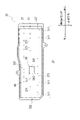
- FIG. 2 is a schematic diagram of the strainer viewed from above.
- FIG. 3 is a cross-sectional view taken along line AA of FIG.
- FIG. 4 is a schematic diagram of the lower case viewed from above.
- FIG. 5 is a schematic diagram of the upper case viewed from below.
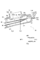
- FIG. 6 is an enlarged view around the front end of the strainer.
- FIG. 7 is a diagram showing oil flow in the strainer when both the mechanical oil pump and the electric oil pump are in operation.
- FIG. 8 is a diagram showing the flow of oil in the strainer when only the mechanical oil pump is operating.
- FIG. 9 is a diagram for explaining the flow of oil near the supply port.
- FIG. 10 is a diagram showing a modification.
- “Overlapping when viewed from a predetermined direction” means that a plurality of elements are arranged in a predetermined direction, and has the same meaning as “overlapping in a predetermined direction”.
- the "predetermined direction” is, for example, the axial direction, the radial direction, the direction of gravity (vertical direction), the longitudinal direction of the vehicle, or the like. If a drawing shows that multiple elements (parts, parts, etc.) are lined up in a predetermined direction, there is a sentence in the description explaining that they overlap when viewed in a predetermined direction. can be regarded as
- not overlapped when viewed from a predetermined direction and “offset when viewed from a predetermined direction” mean that a plurality of elements are not aligned in a predetermined direction, and "not overlapped in a predetermined direction”. , is synonymous with the description of "offset in a predetermined direction".
- the "predetermined direction” is, for example, the axial direction, the radial direction, the direction of gravity, the longitudinal direction of the vehicle (the forward direction of the vehicle, the backward direction of the vehicle), or the like. If a drawing shows that multiple elements (parts, parts, etc.) are not aligned in a predetermined direction, the description of the specification includes a sentence explaining that they do not overlap when viewed in a predetermined direction. can be regarded as
- the first element is located between the second element (part, portion, etc.) and the third element (part, portion, etc.) when viewed from a predetermined direction" In the case it means that the first element can be observed to be between the second and third elements.
- the "predetermined direction” includes an axial direction, a radial direction, a gravity direction, a vehicle running direction (vehicle forward direction, vehicle backward direction), and the like. For example, when the second element, the first element, and the third element are arranged in this order along the axial direction, the first element is between the second element and the third element when viewed in the radial direction.
- the drawing shows that the first element is between the second element and the third element when viewed from a predetermined direction
- the first element is the second element when viewed from a predetermined direction in the description of the specification. It can be considered that there is a sentence explaining what is between the third element.
- a strainer provided in an oil supply device installed in a vehicle will be described.
- the oil supply device supplies oil to, for example, a belt-type continuously variable transmission that operates hydraulically.
- FIG. 1 is a schematic diagram showing the configuration of the oil supply device 1.
- the vehicle is provided with a transmission case 7 that accommodates a transmission mechanism (not shown) of a belt-type continuously variable transmission.
- An oil pan 9 that stores oil OL is provided at the lower portion of the transmission case 7 in the direction of the vertical line VL.
- the vertical line VL direction means the vertical line VL direction based on the mounted state of the transmission case 7 in the vehicle.
- “upper”, “upper”, “lower”, and “lower” refer to “upper” in the direction of the vertical line VL with reference to the mounting state of the transmission case 7 on the vehicle. , means “above”, “below”, “below”.
- the terms “front side” and “rear side” mean “front side” and "rear side” in the longitudinal direction of the vehicle.
- the oil pan 9 covers the lower opening of the transmission case 7.
- An oil reservoir PL which is an oil source, is formed in the oil pan 9 .
- the oil OL in the oil reservoir PL tends to be biased toward the rear side in the longitudinal direction of the vehicle. Therefore, the oil pan 9 attached to the transmission case 7 is inclined upward from the rear toward the front in the longitudinal direction of the vehicle.
- the depth from the liquid surface to the bottom surface of the oil pool PL is deeper on the rear side than on the front side. That is, more oil OL is stored in the oil reservoir PL on the rear side than on the front side.
- the oil supply device 1 has a mechanical oil pump 11 (first oil pump), an electric oil pump 12 (second oil pump), a control valve body 20 and a strainer 30.
- first oil pump first oil pump
- electric oil pump 12 second oil pump
- control valve body 20 a strainer 30.
- FIG. 1 the mechanical oil pump 11, the electric oil pump 12 and the control valve body 20 are schematically shown.
- the mechanical oil pump 11 and the electric oil pump 12 suck the oil OL from the oil reservoir PL.
- the mechanical oil pump 11 is an oil pump that is driven by rotation input from a vehicle drive source such as the engine ENG.
- the mechanical oil pump 11 is switched between operation and stop in conjunction with operation and stop of the vehicle drive source.
- the electric oil pump 12 is driven by rotation input from a motor M installed separately from the vehicle drive source.
- the electric oil pump 12 is switched between operation and stop by switching operation and stop of the motor by a control device (not shown).
- the electric oil pump 12 is driven, for example, when the supply of the oil OL by the mechanical oil pump 11 is stopped or when the amount of oil OL supplied from the mechanical oil pump 11 is insufficient. That is, the electric oil pump 12 is intermittently driven.
- the electric oil pump 12 may be operated instead of the mechanical oil pump 11 when the mechanical oil pump 11 is stopped, such as when the vehicle is stopped idling.
- the electric oil pump 12 may be operated together with the mechanical oil pump 11 when a large hydraulic pressure is required, such as a downshift of a belt-type continuously variable transmission.
- a pressure regulating circuit is provided inside the control valve body 20 .
- the pressure of the oil OL discharged by the mechanical oil pump 11 and the electric oil pump 12 is regulated by the pressure regulating circuit and supplied to the transmission mechanism.
- the strainer 30 is arranged below the control valve body 20 . Similar to the oil pan 9, the strainer 30 is inclined upward from the rear toward the front in the longitudinal direction of the vehicle.
- the strainer 30 is connected to the electric oil pump 12 and the mechanical oil pump 11 via oil passages (not shown) formed inside the control valve body 20 .
- the strainer 30 filters the oil OL in the oil reservoir PL and supplies it to the electric oil pump 12 and the mechanical oil pump 11 .
- FIG. 2 is a schematic diagram of the strainer 30 viewed from above.
- FIG. 3 is a cross-sectional view taken along line AA of FIG.
- FIG. 4 is a schematic diagram of the lower case 32 viewed from above.
- FIG. 5 is a schematic diagram of the upper case 33 viewed from below.
- FIG. 6 is an enlarged view around the front end portion 31B of the strainer 30. As shown in FIG.
- the strainer 30 has a substantially rectangular parallelepiped case 31 .
- a filter 40 for filtering the oil OL is arranged inside the case 31.
- the position of the filter 40 is indicated by phantom lines.
- the case 31 has a rectangular shape when viewed from above.
- the case 31 is arranged such that its longitudinal direction extends along the longitudinal direction of the vehicle.
- the lateral direction of the case 31 is arranged along the vehicle width direction.
- the vehicle width direction is a direction perpendicular to the longitudinal direction of the vehicle and the direction of the vertical line VL.
- the case 31 has one end positioned rearward in the vehicle front-rear direction (hereinafter referred to as a rear end 31A) and the other end positioned forward (hereinafter referred to as a front end 31B).
- the rear end portion 31A and the front end portion 31B are arranged along the vehicle width direction.
- the case 31 has side ends 31C, 31C connecting the rear end 31A and the front end 31B at both ends in the vehicle width direction.
- Side ends 31C, 31C extending in the longitudinal direction of case 31 are arranged along the longitudinal direction of the vehicle.
- the case 31 is composed of a lower case 32 and an upper case 33.
- the lower case 32 includes a rectangular bottom wall portion 321 and a peripheral wall portion 322 that surrounds the outer peripheral edge of the bottom wall portion 321 and extends upward.
- the upper case 33 includes a rectangular upper wall portion 331 and a peripheral wall portion 332 that surrounds the outer peripheral edge of the upper wall portion 331 and extends downward.
- the upper end flange F of the peripheral wall portion 322 of the lower case 32 and the lower end flange F of the peripheral wall portion 332 of the upper case 33 are overlapped and joined.
- the bottom wall portion 321 of the lower case 32 is provided with an inflow port 34 for the oil OL.
- the inlet 34 is composed of an opening 341 formed in the bottom wall 321 and a peripheral wall 342 surrounding the opening 341 .
- the peripheral wall portion 342 protrudes downward in the direction of the vertical line VL.
- the peripheral wall portion 342 communicates with the outside of the case 31 at its lower end.
- the upper wall portion 331 of the upper case 33 is provided with two supply ports 35 and 36 .
- the supply ports 35 and 36 are spaced apart in the front-rear direction of the vehicle.
- the supply ports 35 and 36 are offset in the vehicle width direction. In other words, the supply ports 35 and 36 do not overlap when viewed from the vehicle front-rear direction.
- the supply port 35 (first supply port) is provided near the rear end portion 31A of the case 31 .
- a supply port 36 (second supply port) is provided near the front end portion 31B of the case 31 .
- the upper case 33 has an inclined portion 33A on the front end portion 31B side (right side in the drawing) of the substantially central portion in the vehicle front-rear direction.
- 33 A of inclination parts incline so that it may be located upwards, as it leaves
- the supply port 36 is positioned at the inclined portion 33A. Due to the inclination of the inclined portion 33A, the supply port 36 is positioned above (above) the supply port 35 in the direction of the vertical line VL.
- the lower case 32 also has an inclined portion 32A on the front end portion 31B side.
- the inclined portion 32A is located closer to the front end portion 31B (right side in the drawing) than the inlet 34 in the vehicle front-rear direction.
- 32 A of inclination parts incline so that it may be located on the upper side as it leaves
- the lower case 32 is not limited to having the inclined portion 32A.
- the front end portion 31B side of the lower case 32 may be substantially horizontal with respect to the rear end portion 31A side.
- the supply port 35 includes an opening 351 penetrating the upper wall portion 331 in the direction of the vertical line VL, and a cylindrical portion 352 surrounding the opening 351 .
- the tubular portion 352 protrudes upward in the vertical line VL direction.
- the cylindrical portion 352 communicates with the outside of the case 31 at its upper end.
- the supply port 36 includes an opening 361 penetrating the upper wall 331 in the direction of the vertical line VL, and a tubular portion 362 surrounding the opening 361 .
- the tubular portion 362 protrudes upward in the vertical line VL direction.
- the cylindrical portion 362 communicates with the outside of the case 31 at its upper end.
- the supply port 36 is inclined along the inclination of the inclined portion 33A.
- the supply port 36 is slanted upward as it moves away from the rear end 31A.
- an end portion (hereinafter referred to as an upper end 363b) on the front end portion 31B side of the opening portion 361 (hereinafter referred to as a lower end 363a) is positioned in the direction of the vertical line VL. located on the upper side.
- a lower end 363 a of the opening 361 corresponds to the lower end of the supply port 36 .
- the supply port 35 communicates with the mechanical oil pump 11 through an oil passage (not shown) formed inside the control valve body 20 .
- the supply port 36 communicates with the electric oil pump 12 via an oil passage (not shown) formed inside the control valve body 20 .
- the supply port 36 is provided with a check valve. When the electric oil pump 12 is stopped, the check valve closes the oil passage communicating with the supply port 36 in order to prevent backflow of the oil OL.
- the position of the inflow port 34 is indicated by a phantom line.
- the inflow port 34 is provided near the center in the vehicle longitudinal direction and the vehicle width direction.
- the inflow port 34 is provided apart from the supply port 35 and the supply port 36 when viewed from above.
- the inflow port 34 is positioned between the supply port 35 and the supply port 36 in the vehicle front-rear direction.
- the inflow port 34 partially overlaps the supply port 35 when viewed from the front-rear direction of the vehicle.
- the inflow port 34 partially overlaps the supply port 36 when viewed from the vehicle front-rear direction.
- each rib row 37 is formed from a plurality of ribs 371 arranged along the longitudinal direction of the vehicle. As shown in FIG. 3, each rib 371 protrudes upward in the direction of the vertical line VL from the bottom wall portion 321 of the lower case 32.
- a plurality of ribs 371 are arranged at intervals in the longitudinal direction of the vehicle to form rib rows 37 .
- a plurality of rib rows 37 extending in the longitudinal direction of the vehicle are arranged at intervals in the vehicle width direction.
- the ribs 371 illustrated in FIGS. 3 and 4 are merely examples. The dimensions of the ribs 371, the intervals between the ribs 371, and the like can be set as appropriate. Also, the intervals between the rib rows 37, the range of forming the rib rows 37, and the like can be set as appropriate.
- each rib row 38 is formed from a plurality of ribs 381 arranged along the longitudinal direction of the vehicle. As shown in FIG. 3, each rib 381 protrudes downward in the vertical line VL direction from the upper wall portion 331 of the upper case 33 .
- a plurality of ribs 381 are arranged at intervals in the longitudinal direction of the vehicle to form rib rows 38 .
- a plurality of rib rows 38 extending in the longitudinal direction of the vehicle are arranged at intervals in the vehicle width direction.
- the ribs 381 illustrated in FIGS. 3 and 5 are merely examples.
- the dimensions of the ribs 381, the intervals between the ribs 381, and the like can be set as appropriate.
- the intervals between the rib rows 38, the range in which the rib rows 38 are formed, and the like can be set as appropriate.
- the filter 40 has a bag-like main body 41 and an opening 42 provided at the bottom of the main body 41 . Contaminants contained in the oil OL are removed when the oil OL that has entered the inside of the main body portion 41 seeps out.
- the filter 40 can be made of, for example, non-woven fabric.
- the opening 42 of the filter 40 is fixed to the inlet 34 of the lower case 32 by welding or the like.
- a body portion 41 of the filter 40 is fixed to the case 31 .
- the body portion 41 is sandwiched between the flange F of the peripheral wall portion 322 of the lower case 32 and the flange F of the peripheral wall portion 332 of the upper case 33 . That is, the flanges F of the peripheral wall portions 322 and 332 function as fixing portions for the filter 40 .
- hatching indicates the range of the case 31 where the fixed portion of the filter 40 is provided.
- the filter 40 is fixed by a fixing portion FA (first fixing portion).
- the filter 40 is fixed by a fixing portion FB (second fixing portion) at the side ends 31C, 31C.
- Filter 40 is not fixed at front end 31B of case 31 . That is, the front end portion 31B of the case 31 is not provided with a fixing portion for the filter 40 . As shown in FIG. 3, a gap is formed between the main body portion 41 of the filter 40 and the front end portion 31B.
- the main body 41 of the filter 40 is sandwiched between rib rows 37 and 38 formed on the lower case 32 and the upper case 33 in the internal space of the case 31 .
- the body portion 41 is sandwiched between the rib rows 37 and 38 so as to be positioned so as to extend over the entire internal space of the case 31 . Furthermore, a gap is secured between the filter 40 and the case 31 by the rib rows 37 and 38 . As a result, even if the oil OL flows into the body portion 41 of the filter 40 and expands, sticking of the body portion 41 to the case 31 is reduced.
- the oil OL is filtered by exuding from the inside of the main body portion 41 to the outside.
- the oil OL that has once leaked out of the body portion 41 does not return to the inside of the body portion 41 .
- the oil OL that has leaked out of the body portion 41 flows through the gap between the filter 40 and the case 31 . That is, the gap between the filter 40 and the case 31 forms an oil passage through which the oil OL flowing out from the inside of the filter 40 flows.
- a lower oil passage 52 is formed between the body portion 41 of the filter 40 and the lower portion of the case 31 .
- An upper oil passage 53 is formed between the main body portion 41 of the filter 40 and the upper portion of the case 31 .
- Supply ports 35 and 36 formed in the upper portion of the case 31 are open to the upper oil passage 53 .
- a gap is also formed between the main body portion 41 and the front end portion 31B of the case 31.
- This gap forms the end oil passage 51 .
- the end oil passage 51 connects the lower oil passage 52 and the upper oil passage 53 at the front end portion 31B of the case 31 .
- the body portion 41 of the filter 40 is inclined along the inclinations of the inclined portions 33A and 32A of the case 31 .
- the front end portion 31B side of the main body portion 41 is inclined so that it is positioned higher than the rear end portion 31A side.
- the body portion 41 has a region located below the supply port 36 .
- the end portion 45 of the main body portion 41 on the front end portion 31B side corresponds to the region located below the supply port 36 .
- the "region located below the supply port 36" includes a region located below the opening 361 of the supply port 36 in the direction of the vertical line VL and the surrounding region.
- the end portion 45 is positioned closer to the front end portion 31B than the vertical line VL1 extending from the lower end 363a of the supply port 36.
- the end portion 45 is further positioned closer to the front end portion 31B than the vertical line VL2 extending from the upper end 363b. That is, the end portion 45 overlaps the entire opening 361 of the supply port 36 in the direction of the vertical line VL.
- the end portion 45 faces the opening portion 361 of the supply port 36 through the gap formed by the rib row 38 .
- the end portion 45 extends beyond the vertical line VL2.
- An upper end 43 of the end portion 45 is positioned near the front end portion 31B.
- the upper end 43 is the uppermost portion of the end portion 45 in the direction of the vertical line VL.
- the end oil passage 51 and the upper oil passage 53 are connected at the position of the upper end 43 .
- a horizontal line extending from the upper end 43 of the filter 40 is indicated by HL1
- a horizontal line extending from the lower end 363a of the opening 361 of the supply port 36 is indicated by HL2.
- the horizontal line HL1 is located above the horizontal line HL2 in the direction of the vertical line VL. That is, the upper end 43 of the filter 40 is located above the lower end 363a of the supply port 36.
- FIG. 7 is a diagram showing the flow of oil OL in strainer 30 when both mechanical oil pump 11 and electric oil pump 12 are in operation.
- FIG. 8 is a diagram showing the flow of the oil OL inside the strainer 30 when only the mechanical oil pump 11 is operating.
- FIG. 9 is a diagram for explaining the flow of the oil OL near the supply port 36. As shown in FIG. In FIGS. 7 to 9, arrows indicate the flow of the oil OL. Further, in FIGS. 7 to 9, illustration of ribs is omitted for the sake of clarity.
- the oil OL stored in the oil reservoir PL of the oil pan 9 is sucked into the strainer 30 .
- the oil OL flows into the body portion 41 of the filter 40 through the opening 42 of the filter 40 welded to the inlet 34 of the strainer 30 .
- the rib rows 37 and 38 are arranged along the vehicle front-rear direction (the direction from the rear end portion 31A to the front end portion 31B) on the lower and upper portions of the case 31 (FIGS. 4 and 5). reference). Therefore, the oil OL that has flowed into the lower oil passage 52 and the upper oil passage 53 flows along the longitudinal direction of the vehicle.
- the oil OL that has flowed into the lower oil passage 52 flows toward the front end portion 31B of the strainer 30 due to the suction forces of the mechanical oil pump 11 and the electric oil pump 12 .
- the oil OL flows into the end oil passage 51 at the front end 31B.
- the oil OL that has flowed into the end oil passage 51 from the body portion 41 moves upward due to the suction forces of the mechanical oil pump 11 and the electric oil pump 12 and flows into the upper oil passage 53 .
- the oil OL that has flowed from the lower oil passage 52 into the end oil passage 51 also flows into the upper oil passage 53 .
- the filter 40 is sandwiched and fixed by the case 31 on the rear end portion 31A side and the side end portions 31C, 31C of the case 31 (see FIG. 2). Therefore, between the filter 40 and the rear end portion 31A and the side ends 31C, 31C (see FIG. 2), an oil passage connecting the lower oil passage 52 and the upper oil passage 53, such as the end oil passage 51, is provided. does not exist. Therefore, the oil OL that has flowed out to the lower oil passage 52 does not directly flow into the upper oil passage 53 from the rear end portion 31A side and the side end portions 31C, 31C.
- the oil OL that has directly flowed out from the body portion 41 of the filter 40 into the upper oil passage 53 is directed toward the supply port 35 or the supply port 36 .
- the oil OL directed to the supply port 35 is sucked by the mechanical oil pump 11 .
- the oil OL directed to the supply port 36 is sucked by the electric oil pump 12 .
- the oil OL that has flowed from the end oil passage 51 into the upper oil passage 53 is directed to the supply port 36 provided near the front end 31B and is sucked by the electric oil pump 12 .
- the strainer 30 sucks the oil OL stored in the oil reservoir PL (see FIG. 1).
- the oil OL in the oil pool PL is agitated by the rotation of the transmission mechanism, and then drops into the oil pan 9 along the wall surface of the transmission case 7 and the like. Therefore, the oil OL sucked into the strainer 30 contains a large amount of air.
- the air contained in the oil OL tends to move inside the strainer 30 upward in the direction of the vertical line VL due to buoyancy and form an air pool.
- the strainer 30 is inclined so that the front end portion 31B of the case 31 is located above the rear end portion 31A in the vertical line VL direction.
- a supply port 36 of the electric oil pump 12 is positioned near the front end portion 31B of the case 31 . Therefore, as shown in FIG. 9, the floating air tends to stay around the supply port 36 near the front end portion 31B of the strainer 30 .
- the electric oil pump 12 While the electric oil pump 12 is operating, the electric oil pump 12 sucks the air-containing oil OL through the supply port 36 . Therefore, air pockets are less likely to be formed.
- the check valve closes the oil passage (not shown) connected to the supply port 36 while the electric oil pump 12 is stopped. Therefore, an air pool is likely to be formed around the supply port 36 .
- the configuration of the embodiment makes it easy to reduce air pools formed around the supply port 36 .
- the upper oil passage 53 is formed between the filter 40 and the upper portion of the case 31 .
- the filter 40 has an end portion 45 as a region located below the supply port 36 . That is, the upper oil passage 53 communicating with the supply port 35 extends below the supply port 36 .
- the operation of the mechanical oil pump 11 causes the oil OL to flow toward the supply port 35 below the supply port 36 .
- the oil OL takes in air remaining around the supply port 36 and pushes the air toward the supply port 35 (left side in the drawing). This can reduce the formation of air pockets around the supply port 36 .
- the “region located below the supply port 36 ” of the filter 40 means a region below the supply port 36 where the oil flow toward the supply port 35 can be formed. That is, the “region located below the supply port 36” of the filter 40 is not limited to the region below the opening 361 of the supply port 36 in the vertical line VL direction, but can include the surrounding region.
- the end portion 45 of the filter 40 is preferably positioned near the vertical line VL1 extending from the lower end 363a of the supply port 36 .
- the end portion 45 of the filter 40 is more preferably located closer to the front end portion 31B than the vertical line VL1.
- the end portion 45 overlaps the opening 361 of the supply port 36 in the direction of the vertical line VL, the flow of oil toward the supply port 35 is likely to be formed below the supply port 36 . More preferably, the upper end 43 of the end portion 45 is located closer to the front end portion 31B than the vertical line VL2. Since the end portion 45 overlaps the entire opening 361 in the direction of the vertical line VL, the flow of the oil OL toward the supply port 35 is likely to be formed below the supply port 36 .
- the filter 40 is not positioned below the supply port 36 .
- the upper end 43 of the filter 40 is located at a position farther from the vertical line VL1 extending from the lower end 363a of the supply port 36 toward the supply port 35 (to the left in the drawing).
- the end portion 45 does not overlap the opening 361 of the supply port 36 in the vertical line VL direction. That is, the upper oil passage 53 does not extend below the supply port 36 .
- the electric oil pump 12 may suck in a large amount of air and spin, delaying the discharge of the oil OL. Since the electric oil pump 12 is driven when a large oil pressure is required, such as when the vehicle is downshifted, it is desirable to quickly discharge the oil OL.
- the supply port 36 for example, in the lower portion of the case 31 so that an air pool is not formed around the supply port 36.
- the downward projection length of the case 31 is increased by the amount that the supply port 36 is provided in the lower portion.
- the vehicle is required to ensure minimum ground clearance, and thus the layout of the oil supply device 1 and other vehicle components is likely to be restricted.
- the body portion 41 has an end portion 45 as a region located below the supply port 36.
- the oil OL that has flowed out from the interior of the main body 41 to the upper oil passage 53 via the end 45 passes below the supply port 36 due to the suction force of the mechanical oil pump 11 and is supplied. Head to mouth 35.
- the end portion 45 overlaps the entire opening 361 of the supply port 36 in the direction of the vertical line VL, the amount of the oil OL passing below the supply port 36 can be increased.
- the end portion 45 extends to the front end portion 31B.
- An upper end 43 of the end portion 45 connects the upper oil passage 53 and the end oil passage 51 .
- the oil OL flowing out from the inside of the main body 41 into the lower oil passage 52 and the end oil passage 51 also flows into the upper oil passage 53 via the upper end 43 and passes below the supply port 36 .
- the upper end 43 of the end portion 45 is located above the lower end 363a of the supply port 36 in the direction of the vertical line VL. That is, the oil OL flows from the upper end 43 on the upper side toward the supply port 36 on the lower side. Therefore, when the oil OL passes below the supply port 36 , it is likely to come into contact with air remaining around the supply port 36 .
- fixed portions FA and FB of the filter 40 are provided at the rear end portion 31A and the side end portions 31C and 31C of the case 31 .
- the front end portion 31B positioned near the supply port 36 is not provided with a fixing portion for the filter 40 .
- An end oil passage 51 is provided in the front end portion 31B. Therefore, as shown in FIGS. 7 and 8, the oil OL flowing out from the main body 41 into the lower oil passage 52 moves directly to the upper oil passage 53 at the rear end 31A and the side ends 31C, 31C of the case 31. is prevented.
- the oil OL that has flowed out from the main body portion 41 into the lower oil passage 52 passes through the end oil passage 51 of the front end portion 31B, reaches the upper oil passage 53, and passes below the supply port . Thereby, even when the suction of the electric oil pump 12 is stopped, the flow of the oil OL passing below the supply port 36 can be ensured, and the formation of air pools can be easily reduced.
- the strainer 30 includes an inflow port 34 for the oil OL, a filter 40 through which the oil OL that has flowed in from the inlet 34 passes from the inside toward the outside; a supply port 35 (first supply port) for supplying the oil OL that has passed through the filter 40 to the mechanical oil pump 11 (first oil pump); and a supply port 36 (second supply port) for supplying the oil OL that has passed through the filter 40 to the intermittently driven electric oil pump 12 (second oil pump).
- the supply port 36 is located above (above) the supply port 35 in the direction of the vertical line VL.
- Filter 40 has an end 45 , which is the area located below inlet 36 .
- the strainer 30 has a case 31 in which the filter 40 is arranged.
- the supply port 35 is formed near the rear end portion 31A (one end portion) of the upper portion of the case 31 .
- the supply port 36 is formed near the front end portion 31B (the other end portion) of the upper portion of the case 31 .
- Case 31 is arranged in oil pan 9 that stores oil OL.
- the upper portion of the case 31 has an inclined portion 33A on the front end portion 31B side.
- the inclined portion 33A is inclined so as to be positioned upward in the direction of the vertical line VL as it moves away from the rear end portion 31A.
- the inclined portion 33A positions the supply port 36 above the supply port 35 in the direction of the vertical line VL.
- air contained in the oil OL floats, and an air pool is likely to be formed around the supply port 36 .
- the electric oil pump 12 sucks a large amount of air and spins idle.
- the electric oil pump 12 may delay the discharge of the oil OL due to idling.
- end 45 of filter 40 is located below supply port 36 . As a result, even when the electric oil pump 12 is stopped, the flow of the oil OL is formed by the suction of the mechanical oil pump 11 .
- the oil OL passes below the supply port 36 and flows toward the supply port 35 .
- the oil OL When the oil OL passes under the supply port 36 , the oil OL takes in air remaining around the supply port 36 and pushes it toward the supply port 35 side. This reduces the formation of air pockets around the feed port 36 . By reducing the air intake of the electric oil pump 12, the electric oil pump 12 can quickly discharge the oil OL.
- end portion 45 of the filter 40 (the region located below the filter) preferably overlaps the supply port 36 (second supply port) in the vertical line VL direction. With such a configuration, end 45 extends all the way below feed port 36 . It is possible to increase the amount of the oil OL that passes below the supply port 36 and pushes the air away.
- the end 45 of the filter 40 (the region located below the filter 40) preferably extends from below the supply port 36 (second supply port) to the front end 31B (the other end) of the case 31. do.
- the upper end 43 located at the front end 31B (the other end) of the case 31 of the end 45 of the filter 40 (the region located below the filter 40) is preferably the supply port 36 (second supply port ) in the direction of the vertical line VL (above).
- the oil OL flows from the upper end 43 on the upper side toward the supply port 36 on the lower side. Therefore, when the oil OL passes below the supply port 36 , it is likely to come into contact with the air remaining around the supply port 36 .
- the case 31 preferably has a fixing portion FA (first fixing portion) that is provided at the rear end portion 31A and fixes the filter 40 .
- the case 31 preferably has an end oil passage 51 provided at the front end portion 31 ⁇ /b>B and guiding the oil OL that has passed from the inside of the filter 40 to the lower portion of the case 31 to the upper portion of the case 31 .
- the fixed portion FA can be composed of, for example, a flange F at the upper end of the peripheral wall portion 322 of the lower case 32 and a flange F at the lower end of the peripheral wall portion 332 of the upper case 33 .
- a body portion 41 of the filter 40 is sandwiched between the lower case 32 and the upper case 33 and fixed. As a result, there is no need to provide a fixture for the filter 40 separately. The number of parts of the strainer 30 can be reduced. Further, since the main body portion 41 is sandwiched between the lower case 32 and the upper case 33, it is possible to prevent the oil OL from moving from the lower portion to the upper portion of the case 31 at the rear end portion 31A.
- the case 31 preferably has a fixing portion FB (second fixing portion) for fixing the filter 40 .
- the fixing portion FB can be provided at the side ends 31C, 31C connecting the rear end portion 31A and the front end portion 31B.
- the fixed portion FB can be composed of, for example, a flange F at the upper end of the peripheral wall portion 322 of the lower case 32 and a flange F at the lower end of the peripheral wall portion 332 of the upper case 33 .
- a body portion 41 of the filter 40 is fixed by being sandwiched between the flanges F of the lower case 32 and the upper case 33 .
- the number of parts of the strainer 30 can be reduced. Further, by sandwiching the body portion 41 between the lower case 32 and the upper case 33, it is possible to prevent the oil OL from moving from the bottom to the top of the case 31 at the side ends 31C, 31C.
- the oil OL is easily guided to the front end portion 31B provided with the end oil passage 51 .
- the oil OL moves from the end oil passage 51 of the front end portion 31B to the upper portion of the case 31, the oil OL passes below the supply port 36 provided near the front end portion 31B. This makes it easier for the oil OL to wash away the air around the supply port 36 .
- the strainer 30 preferably includes ribs 371 (first ribs). Ribs 371 are formed in the lower portion of case 31 . The rib 371 protrudes toward the top of the case 31 . The rib 371 is arranged along the direction from the rear end portion 31A to the front end portion 31B, that is, along the vehicle front-rear direction.
- a gap is secured between the filter 40 and the lower part of the case 31 by the rib 371 .
- This gap forms a lower oil passage 52 through which the oil OL flowing out from the filter 40 to the lower portion of the case 31 flows. Further, by arranging the ribs 371 along the vehicle front-rear direction, the oil OL in the lower oil passage 52 is guided to flow into the end oil passage 51 formed on the front end portion 31 ⁇ /b>B side of the case 31 .
- the strainer 30 preferably includes ribs 381 (second ribs).
- a rib 381 is formed on the upper portion of the case 31 .
- the rib 381 protrudes toward the lower portion of the case 31 .
- the rib 381 is arranged along the direction from the front end portion 31B to the rear end portion 31A.
- a gap is secured between the filter 40 and the upper portion of the case 31 by the rib 381 .
- This gap forms an upper oil passage 53 for circulating the oil OL that has flowed into the upper portion of the case 31 .
- a rib 381 is arranged along the vehicle front-rear direction. As a result, the oil OL of the upper oil passage 53 is guided to the supply port 35 provided on the rear end portion 31A side and the supply port 36 provided on the front end portion 31B side.
- the filter 40 may be fixed to a portion of the front end portion 31B by a fixture or the like.
- the end oil passage 51 may be formed in a portion of the front end portion 31B where the fixture is not provided.
- FIG. 6 and the like illustrate an example in which the end portion 45 of the filter 40 extends from below the supply port 36 to the front end portion 31B of the case 31, but it is not limited to this aspect.
- the arrangement of the filter 40 can be changed as appropriate as long as the filter 40 has a region located below the supply port 36 .
- FIG. 10 is a diagram showing a modification. 10, the end portion 45 of the filter 40 is positioned closer to the front end portion 31B than the vertical line VL1 extending from the lower end 363a of the supply port 36. In FIG. However, the end portion 45 is positioned closer to the rear end portion 31A than the vertical line VL2 extending from the upper end 363b of the supply port . That is, the end portion 45 overlaps part of the opening 361 of the supply port 36 in the direction of the vertical line VL.
- the upper end 43 of the end portion 45 is positioned above the lower end 363a of the supply port 36 in the direction of the vertical line VL.
- the upper end 43 may be positioned below the lower end 363a of the supply port 36 in the vertical line VL direction.
- the upper end 43 may be positioned above the upper end 363b of the supply port 36 in the direction of the vertical line VL.
- the strainer is provided in the oil supply device installed in the vehicle, but the present invention is not limited to this aspect.
- the strainer can also be applied to an oil supply device installed outside the vehicle.
- Oil supply device 9 Oil pan 11 Mechanical oil pump (first oil pump) 12...Electric oil pump (second oil pump) 30 Strainer 31 Case 31A Rear end (one end) 31B front end (other end) 31C Side end portion 32 Lower case 32A Inclined portion 33 Upper case 33A Inclined portion 34 Inflow port 34 Supply port (first supply port) 36 ... supply port (second supply port) 371 Rib (first rib) 381 Rib (second rib) 40... Filter 43... Upper end 45... End (region located below the filter) 51 End oil passage 52 Lower oil passage 53 Upper oil passage FA Fixed portion (first fixed portion) FB: Fixed part (second fixed part)
Landscapes
- Engineering & Computer Science (AREA)
- General Engineering & Computer Science (AREA)
- Mechanical Engineering (AREA)
- General Details Of Gearings (AREA)
Priority Applications (3)
| Application Number | Priority Date | Filing Date | Title |
|---|---|---|---|
| CN202280012279.8A CN116783412A (zh) | 2021-01-29 | 2022-01-26 | 滤清器 |
| US18/260,265 US12188614B2 (en) | 2021-01-29 | 2022-01-26 | Strainer |
| JP2022578441A JP7337471B2 (ja) | 2021-01-29 | 2022-01-26 | ストレーナ |
Applications Claiming Priority (2)
| Application Number | Priority Date | Filing Date | Title |
|---|---|---|---|
| JP2021-013971 | 2021-01-29 | ||
| JP2021013971 | 2021-01-29 |
Publications (1)
| Publication Number | Publication Date |
|---|---|
| WO2022163689A1 true WO2022163689A1 (ja) | 2022-08-04 |
Family
ID=82653577
Family Applications (1)
| Application Number | Title | Priority Date | Filing Date |
|---|---|---|---|
| PCT/JP2022/002823 Ceased WO2022163689A1 (ja) | 2021-01-29 | 2022-01-26 | ストレーナ |
Country Status (4)
| Country | Link |
|---|---|
| US (1) | US12188614B2 (https=) |
| JP (1) | JP7337471B2 (https=) |
| CN (1) | CN116783412A (https=) |
| WO (1) | WO2022163689A1 (https=) |
Citations (4)
| Publication number | Priority date | Publication date | Assignee | Title |
|---|---|---|---|---|
| JPH0224155U (https=) * | 1988-08-02 | 1990-02-16 | ||
| JP2000033207A (ja) * | 1998-07-17 | 2000-02-02 | Nsk Warner Kk | 自動変速機用の流体フィルタ装置 |
| JP2002235840A (ja) * | 2001-02-09 | 2002-08-23 | Nok Corp | 自動変速機用流体フィルタ |
| JP2020007996A (ja) * | 2018-07-11 | 2020-01-16 | ジヤトコ株式会社 | オイル供給装置 |
Family Cites Families (10)
| Publication number | Priority date | Publication date | Assignee | Title |
|---|---|---|---|---|
| JP2717271B2 (ja) * | 1988-07-25 | 1998-02-18 | アイシン・エィ・ダブリュ株式会社 | 自動変速機用オイルストレーナ、並びにそれを用いた自動変速機 |
| DE19626212C2 (de) * | 1996-06-29 | 1998-04-23 | Luk Fahrzeug Hydraulik | Ölsaugfilter |
| US5853577A (en) * | 1997-09-22 | 1998-12-29 | Spx Corporation | Orbital vibration welded filter |
| JP4366997B2 (ja) | 2003-05-12 | 2009-11-18 | マツダ株式会社 | 自動変速機のオイル吸入装置 |
| DE102007023641B4 (de) * | 2007-05-22 | 2015-04-02 | Ibs Filtran Kunststoff-/ Metallerzeugnisse Gmbh | Ölfiltervorrichtung |
| JP2010025287A (ja) * | 2008-07-23 | 2010-02-04 | Toyota Motor Corp | 車両のベルト式無段変速装置 |
| EP3434900A4 (en) * | 2016-03-22 | 2019-04-03 | Jatco Ltd. | VENTILATION STRUCTURE OF AN AUTOMATIC TRANSMISSION OIL PUMP AND METHOD OF ASSEMBLING A VENTILATION STRUCTURE |
| US10837329B2 (en) * | 2017-11-16 | 2020-11-17 | GM Global Technology Operations LLC | Flow control system to eliminate air ingestion |
| JP2019215029A (ja) * | 2018-06-12 | 2019-12-19 | ジヤトコ株式会社 | オイルストレーナ |
| CN116964358B (zh) * | 2021-02-02 | 2025-09-09 | 加特可株式会社 | 油压供给装置 |
-
2022
- 2022-01-26 CN CN202280012279.8A patent/CN116783412A/zh active Pending
- 2022-01-26 US US18/260,265 patent/US12188614B2/en active Active
- 2022-01-26 JP JP2022578441A patent/JP7337471B2/ja active Active
- 2022-01-26 WO PCT/JP2022/002823 patent/WO2022163689A1/ja not_active Ceased
Patent Citations (4)
| Publication number | Priority date | Publication date | Assignee | Title |
|---|---|---|---|---|
| JPH0224155U (https=) * | 1988-08-02 | 1990-02-16 | ||
| JP2000033207A (ja) * | 1998-07-17 | 2000-02-02 | Nsk Warner Kk | 自動変速機用の流体フィルタ装置 |
| JP2002235840A (ja) * | 2001-02-09 | 2002-08-23 | Nok Corp | 自動変速機用流体フィルタ |
| JP2020007996A (ja) * | 2018-07-11 | 2020-01-16 | ジヤトコ株式会社 | オイル供給装置 |
Also Published As
| Publication number | Publication date |
|---|---|
| JP7337471B2 (ja) | 2023-09-04 |
| US20240295290A1 (en) | 2024-09-05 |
| CN116783412A (zh) | 2023-09-19 |
| US12188614B2 (en) | 2025-01-07 |
| JPWO2022163689A1 (https=) | 2022-08-04 |
Similar Documents
| Publication | Publication Date | Title |
|---|---|---|
| JP4128085B2 (ja) | 液体タンク | |
| JP5179871B2 (ja) | 変速機のオイルストレーナ | |
| US20140166401A1 (en) | Oil strainer for vehicle transmission | |
| US20110139278A1 (en) | Fuel pump | |
| US8413759B2 (en) | Automatic transmission drive apparatus for vehicle | |
| JP7337471B2 (ja) | ストレーナ | |
| JP4366997B2 (ja) | 自動変速機のオイル吸入装置 | |
| EP1645784B1 (en) | Oil strainer for automatic transmission | |
| JP7580899B2 (ja) | 動力伝達装置 | |
| JP7618375B2 (ja) | 動力伝達装置 | |
| US11224832B2 (en) | Filter cartridge with ventilation device | |
| WO2012073724A1 (ja) | 車両用エンジンのオイルパン構造 | |
| JP2019215028A (ja) | オイルストレーナ | |
| CN114901972B (zh) | 油压供给装置 | |
| US8894455B2 (en) | Outboard motor | |
| JP4063589B2 (ja) | 気泡除去装置 | |
| JP2010019426A (ja) | 液体タンク | |
| JP7618376B2 (ja) | 動力伝達装置 | |
| JP7436513B2 (ja) | 油圧供給装置 | |
| JP6602235B2 (ja) | オイルストレーナ | |
| JP6886530B2 (ja) | オイル供給構造 | |
| JP4467558B2 (ja) | 液体タンク | |
| JPH0972209A (ja) | 内燃機関のバッフルプレート構造 | |
| JP7762079B2 (ja) | オイル循環構造 | |
| JP2007132521A5 (https=) |
Legal Events
| Date | Code | Title | Description |
|---|---|---|---|
| 121 | Ep: the epo has been informed by wipo that ep was designated in this application |
Ref document number: 22744377 Country of ref document: EP Kind code of ref document: A1 |
|
| ENP | Entry into the national phase |
Ref document number: 2022578441 Country of ref document: JP Kind code of ref document: A |
|
| WWE | Wipo information: entry into national phase |
Ref document number: 18260265 Country of ref document: US |
|
| WWE | Wipo information: entry into national phase |
Ref document number: 202280012279.8 Country of ref document: CN |
|
| NENP | Non-entry into the national phase |
Ref country code: DE |
|
| 122 | Ep: pct application non-entry in european phase |
Ref document number: 22744377 Country of ref document: EP Kind code of ref document: A1 |