WO2022163006A1 - 空気流量計測装置、電子制御装置、及び空気流量計測システム - Google Patents
空気流量計測装置、電子制御装置、及び空気流量計測システム Download PDFInfo
- Publication number
- WO2022163006A1 WO2022163006A1 PCT/JP2021/034250 JP2021034250W WO2022163006A1 WO 2022163006 A1 WO2022163006 A1 WO 2022163006A1 JP 2021034250 W JP2021034250 W JP 2021034250W WO 2022163006 A1 WO2022163006 A1 WO 2022163006A1
- Authority
- WO
- WIPO (PCT)
- Prior art keywords
- pulsation
- air flow
- flow rate
- information
- electronic control
- Prior art date
- Legal status (The legal status is an assumption and is not a legal conclusion. Google has not performed a legal analysis and makes no representation as to the accuracy of the status listed.)
- Ceased
Links
Images












Classifications
-
- G—PHYSICS
- G01—MEASURING; TESTING
- G01F—MEASURING VOLUME, VOLUME FLOW, MASS FLOW OR LIQUID LEVEL; METERING BY VOLUME
- G01F1/00—Measuring the volume flow or mass flow of fluid or fluent solid material wherein the fluid passes through a meter in a continuous flow
- G01F1/68—Measuring the volume flow or mass flow of fluid or fluent solid material wherein the fluid passes through a meter in a continuous flow by using thermal effects
-
- G—PHYSICS
- G01—MEASURING; TESTING
- G01F—MEASURING VOLUME, VOLUME FLOW, MASS FLOW OR LIQUID LEVEL; METERING BY VOLUME
- G01F1/00—Measuring the volume flow or mass flow of fluid or fluent solid material wherein the fluid passes through a meter in a continuous flow
- G01F1/72—Devices for measuring pulsing fluid flows
Definitions
- the present invention relates to an air flow measurement device, an electronic control device, and an air flow measurement system.
- the amount of intake air is a parameter used to calculate the amount of fuel injection, and highly accurate detection of the amount of intake air is essential in order to comply with regulations that will become stricter in the future. Since the output result of the airflow sensor influences the fuel consumption and exhaust performance, technical developments are actively being made to improve the detection accuracy of the intake air amount of the airflow sensor.
- a hot wire type airflow sensor is currently widely used as an airflow sensor that can measure the amount of intake air, and the detection signal of this airflow sensor changes the voltage value according to the amount of air based on the signal from the heating resistor.
- Others use a voltage signal or a frequency signal that changes the period of the output pulse depending on the amount of air.
- the reciprocating motion of the piston in an internal combustion engine causes intake pulsation in the intake pipe. Occur.
- Patent Document 1 proposes a method of correcting the air amount with respect to the intake pulsation.
- Patent Document 2 a method as described in Patent Document 2 is disclosed for the problem of increased communication load when information is transmitted between the airflow sensor and the control device by communication.
- a flow rate acquisition unit that acquires the air flow rate based on the air flow rate output, and a pulsation error that is an error in the air flow rate due to air pulsation is corrected based on the air flow rate acquired by the flow rate acquisition section.
- an output unit for outputting the pulsation correction information to an electronic device in addition to the air flow rate.
- the method of correcting the intake air amount described in Patent Document 1 is a method of calculating the correction amount based on the intake pipe pressure, the manipulated variable of the throttle valve, or the engine speed when calculating the pulsation amplitude ratio of the intake air. be.
- the method described in Patent Document 2 obtains pulsation correction information in the airflow sensor and transmits it to the control device via communication in order to reduce the communication load when communicating between the airflow sensor and the control device. It is a way to In this method, since the pulsation correction information is acquired by the airflow sensor, the advantage is that high-speed sampling is possible. In addition, since the airflow sensor does not have engine angle information, it is unclear how long the information used for pulsation calculation should be retained, and there is a problem that it is difficult to calculate the amplitude when the pulsation waveform includes harmonics. be. In particular, when the engine is in a low speed range, there is concern that the retention period of information used for pulsation calculation will be long.
- Patent Document 2 the pulsation is calculated within the airflow sensor.
- the pulsation waveform differs depending on the operating conditions of the engine. Therefore, an advanced estimation technique is required to calculate the pulsation with high accuracy. Also, during transient operating conditions, it is necessary to separate fluctuations and pulsations due to transients.
- the current value flowing through the heating resistor placed in the intake air flow to be measured increases when the amount of intake air is large, and conversely decreases when the amount of intake air is small.
- a bridge circuit is configured to Then, an air amount signal is extracted from the current flowing through the heating resistor.
- the hot wire airflow sensor uses the heat balance of the heating resistor, the detection accuracy is affected by the magnitude and frequency of the intake air pulsation, and the output of the hot wire airflow sensor is particularly high. It has a frequency response characteristic in which response delay occurs in the frequency domain. Therefore, when the output characteristic has a non-linear characteristic, the detected output average value and the true air amount average value do not match, and an error occurs. Also, this error tends to increase as the pulsation increases and the frequency increases.
- an air flow measuring device of one aspect of the present invention measures an air flow rate based on an output signal from a sensing unit arranged in an environment where air flows, and outputs the air flow rate to an electronic control device. It is something to do.
- This air flow measurement device includes a flow rate acquisition unit that acquires the air flow rate based on the output signal, and the electronic control device that corrects the pulsation error of the air flow rate based on the air flow rate acquired by the flow rate acquisition section.
- a pre-stage information acquisition unit that acquires pre-stage information necessary to calculate pulsation correction information for the air flow rate, and an output unit that outputs the pre-stage information to the electronic control device in addition to the air flow rate.
- the electronic control device of one aspect of the present invention controls the internal combustion engine based on the flow rate of air taken into the internal combustion engine.
- This electronic control unit is provided with information necessary for calculating pulsation correction information for correcting the pulsation error of the air flow rate.
- a pulsation correction information calculation unit that calculates pulsation correction information using the number of revolutions of the engine, an air flow rate input from the air flow measurement device, and the air flow rate based on the pulsation correction information calculated by the pulsation correction information calculation unit. and a pulsation corrector for correcting.
- An air flow measurement system of one aspect of the present invention includes the air flow measurement device and the electronic control device.
- the controlled object such as the internal combustion engine can be controlled based on the highly accurate intake air amount.
- FIG. 1 is a schematic configuration diagram showing an example of the overall configuration of an internal combustion engine
- FIG. 1 is an overall configuration diagram of an ECU (electronic control unit)
- FIG. 4 is a block diagram showing a general fuel injection pulse width calculation method
- 4 is a graph showing the relationship between the voltage of the airflow sensor and the amount of air
- Fig. 3 is a graph showing the frequency response (low frequency) of an airflow sensor
- Fig. 3 is a graph showing the frequency response (high frequency) of an airflow sensor
- 5 is a graph showing attenuation of frequency characteristics of an airflow sensor
- Fig. 3 is a graph showing the effect of voltage signal attenuation on average air content
- FIG. 3 is a graph showing the frequency response (small pulsation) of the airflow sensor;
- FIG. 4 is a graph showing the frequency response (great pulsation) of the airflow sensor;
- FIG. 7 is a graph showing the tendency of pulsation errors due to different frequencies;
- FIG. 10 is a block diagram showing intake air amount calculation by conventional pulsation error calculation; It is a figure which shows a pulsation correction map.
- 1 is a block diagram showing an example configuration of an air flow measurement system according to an embodiment of the present invention;
- FIG. 4 is a block diagram showing a configuration example of a pulsation error calculator of an ECU;
- FIG. 4 is a block diagram showing an example of an airflow sensor diagnostic function of an ECU;
- 4 is a graph showing an example of ECU airflow sensor diagnosis;
- FIG. 1 is a schematic configuration diagram showing an example of the overall configuration of an internal combustion engine to which a flow rate measuring system according to an embodiment of the invention is applied.
- the internal combustion engine 10 shown in FIG. 1 is, for example, a spark ignition multi-cylinder engine having four cylinders.
- the internal combustion engine 10 includes a cylinder 29 composed of a cylinder head 29a and a cylinder block 29b, and a piston 27 slidably inserted into each cylinder of the cylinder 29.
- Piston 27 is connected to a crankshaft (not shown) via connecting rod 28 .
- a combustion chamber 26 having a ceiling portion of a predetermined shape is defined above the piston 27 .
- An ignition plug 19 to which a high-voltage ignition signal is supplied from the ignition coil 20 is installed in the combustion chamber 26 of each cylinder.
- the combustion chamber 26 also communicates with an intake passage 15 including an air cleaner 11, a throttle valve 13, a collector 16, an intake manifold 17, an intake port 18, and the like. Air necessary for fuel combustion passes through the intake passage 15 and passes through an intake valve 30 driven to open and close by an intake camshaft 22 disposed at the end of an intake port 18, which is the downstream end of the intake passage 15. , and is drawn into the combustion chamber 26 of each cylinder.
- an injector 21 for injecting fuel toward an intake port 18 is provided on the intake manifold 17 of the intake passage 15 for each cylinder.
- an air flow sensor 12 that detects the amount of intake air is arranged downstream of the air cleaner 11 in the intake passage 15 .
- a mixture of air sucked through the intake passage 15 and fuel injected from the injector 21 is sucked into the combustion chamber 26 through the intake valve 30 and spark-ignited by the spark plug 19 connected to the ignition coil 20.
- burned by Exhaust gas after combustion in the combustion chamber 26 is exhausted from the combustion chamber 26 through an exhaust valve 31 that is driven to open and close by an exhaust camshaft 23, and passes through an exhaust port, an exhaust manifold, an exhaust pipe, etc. (not shown). It is configured to be discharged to the outside atmosphere through an exhaust passage 32 provided.
- a three-way catalyst 35 for purifying exhaust gas which is made by coating a carrier such as alumina or ceria with platinum or palladium, is arranged.
- An air-fuel ratio sensor 33 having a linear output characteristic with respect to the pre-catalyst air-fuel ratio is arranged upstream of the three-way catalyst 35 .
- an O2 sensor 34 is arranged for outputting a switching signal for identifying whether the post-catalyst air-fuel ratio is richer or leaner than the stoichiometric (theoretical air-fuel ratio).
- the injector 21 provided for each cylinder of the internal combustion engine 10 is connected to the fuel tank 36 .
- Fuel in the fuel tank 36 is regulated to a predetermined fuel pressure by a fuel supply mechanism including a fuel pump 37 and a fuel pressure regulator 38 and is supplied to the injector 21 .
- the injector 21 supplied with fuel at a predetermined fuel pressure receives a fuel injection pulse signal having a duty (pulse width: corresponding to the valve opening time) according to the operating state such as the engine load supplied from the ECU (Engine Control Unit) 100. is driven to open the valve.
- the injector 21 is configured to inject an amount of fuel corresponding to the valve opening time toward the intake port 18 .
- the ECU 100 incorporates a microcomputer for performing various controls of the internal combustion engine 10, such as fuel injection control (air-fuel ratio control) by the injector 21, ignition timing control by the spark plug 19, and the like.
- fuel injection control air-fuel ratio control
- ignition timing control by the spark plug 19, and the like.
- FIG. 2 shows the overall configuration of the ECU 100.
- the ECU 100 is an example of an electronic control device, and includes a power supply IC 101 and an LSI 102 .
- a RESET terminal (not shown) of the LSI 102 is connected to the power supply IC 101 so that a RESET signal controlled by the power supply IC 101 can be transmitted.
- the ECU 100 also includes sensors necessary for controlling the internal combustion engine 10, such as a crank angle sensor 25 for detecting the engine speed, a water temperature sensor 40 for detecting the temperature of the cooling water of the internal combustion engine 10, a throttle valve opening Signals from the throttle sensor 14 for detecting the engine speed, the air-fuel ratio sensor 33 for detecting the oxygen concentration in the exhaust gas, the starter switch 41, the air flow sensor 12, etc. are input.
- sensors necessary for controlling the internal combustion engine 10 such as a crank angle sensor 25 for detecting the engine speed, a water temperature sensor 40 for detecting the temperature of the cooling water of the internal combustion engine 10, a throttle valve opening Signals from the throttle sensor 14 for detecting the engine speed, the air-fuel ratio sensor 33 for detecting the oxygen concentration in the exhaust gas, the starter switch 41, the air flow sensor 12, etc.
- Detection signals from these sensors are input to an LSI (input processing circuit) 102 in the ECU 100, and divided into those detected by an A/D converter as analog inputs and those detected at High/Low levels. It is processed.
- LSI input processing circuit
- the CPU 103 executes predetermined digital arithmetic processing according to a program stored in the memory 103M in the LSI 102.
- the CPU 103 has a function of outputting control signals for various actuators necessary for controlling the internal combustion engine 10 based on the calculation results and controlling the various actuators via the output circuit of the LSI 102 .
- the memory 103M is composed of a non-volatile or volatile semiconductor memory, and stores parameters, variables generated during arithmetic processing, a pulsation correction map, a harmonic table, etc., which will be described later.
- the CPU 103 controls the mass flow rate measured from the detection signal of the hot wire airflow sensor 12, the rotation speed of the internal combustion engine 10 measured from the crank angle sensor 25, and the water temperature sensor 40. Each correction amount including the water temperature and a correction amount according to the air-fuel ratio state detected by the air-fuel ratio sensor 33 are added to calculate the fuel injection amount. Then, the CPU 103 outputs a control signal as a drive pulse width to each injector 21 of the internal combustion engine 10 based on the fuel injection amount calculated for each injector 21 . Similarly, the CPU 103 outputs an ignition signal for controlling the energization timing of the ignition coil 20 necessary for combustion of the internal combustion engine 10, a control signal for an electronically controlled throttle (not shown) for controlling the opening of the throttle valve, and the like.
- the hot-wire airflow sensor 12 has, as a main component, a heating resistor placed in the airflow to be measured.
- the hot-wire airflow sensor 12 has a bridge circuit configured so that the current value flowing through the heating resistor increases when the amount of intake air is large, and conversely decreases when the amount of intake air is small.
- a reference numeral 12 takes out the amount of air as a voltage signal based on the current flowing through the heating resistor.
- the voltage signal corresponding to the amount of air is output as a voltage value, and may also be converted to a frequency signal by a voltage-frequency conversion circuit and output.
- the flow rate data is transmitted from the air flow sensor 12 to the ECU 100 using digital communication.
- the air flow sensor 12 outputs the measurement result as a voltage (analog signal) will be explained.
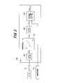
- FIG. 3 shows a calculation method for determining the amount of air based on the output signal of a general hot-wire airflow sensor 12, and this calculation is executed by internal processing of the ECU 100.
- the digital value is 200 when 1.0 V is A/D converted.
- the voltage information Va output from the A/D converter 104 is given to the air amount conversion table 105 .
- the air amount conversion table 105 has pre-stored air amounts corresponding to the voltage information Va.
- the voltage information Va is searched and interpolated by the air amount conversion table 105 and converted into the detected air amount.
- the detected air amount will be described as indicating the air amount converted by the air amount conversion table 105 .
- a frequency signal converted from voltage to frequency is input from the air flow sensor 12 to the ECU 100
- the period of the signal is measured at the port input of the CPU 103, and the period or the period is converted to the frequency.
- the values are input to the air amount conversion table 105 .
- the period or the value converted from the period to the frequency is searched and interpolated from the pre-stored value according to the period or frequency in the air amount conversion table 105 and converted to the detected air amount.
- the air quantity signal Q obtained from the air quantity conversion table 105 is then subjected to digital filtering 106 for the purpose of removing high frequency component noise to calculate the detected air quantity Qc.
- the fuel injection pulse width calculating means 107 divides the detected air amount Qc by the rotational speed of the internal combustion engine 10 (hereinafter referred to as "engine rotational speed") 115 separately calculated from the signal of the crank angle sensor 25 to obtain the air intake to the cylinder 29. Convert to quantity equivalent. Further, after the correction calculations described above are performed, the fuel injection pulse width calculation means 107 calculates the time Tout for injecting fuel, and the injector 21 operates to supply the fuel to the internal combustion engine 10 .
- FIG. 4 shows the relationship between the amount of intake air and the output signal of a general hot-wire airflow sensor 12.
- FIG. 4 shows an example of characteristic curves having a nonlinear relationship in which the voltage of the output signal is low when the amount of intake air is small, and the voltage of the signal is high when the amount of intake air is large.
- the nonlinear characteristic is used because the following equation, called King's equation, is mainly used for the amount of air Q when converting the detection signal from the heating resistor into the amount of air.
- Ih ⁇ Rh ( ⁇ + ⁇ ⁇ ⁇ Q) ⁇ (Th - Ta)
- Ih is the current value of the heating resistor
- Rh is the resistance value of the heating resistor
- Th is the surface temperature of the heating resistor
- Ta is the air temperature
- Q is the air volume
- ⁇ and ⁇ are constants determined by the specifications of the heating resistor. is.
- the current value Ih of the heating resistor is controlled so that (Th ⁇ Ta) is constant, so the amount of air is detected by converting it into a voltage value V due to the voltage drop across the resistor.
- the value V becomes a quartic function expression. For this reason, when converting to an air amount, the curvature of the quartic curve, that is, the relationship between the output and the air amount becomes non-linear.
- the output of the hot-wire airflow sensor 12 is set according to the required air amount of the internal combustion engine 10 . Therefore, there are cases where the relationship between the frequency and the air amount or between the voltage and the air amount has an opposite characteristic or a linear relationship, but only the air amount conversion table 105 changes for the arithmetic processing.
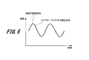
- FIG. 5 shows changes in the actual amount of air and output values of the hot-wire airflow sensor 12 when the pulsation frequency is low. When the pulsation frequency is low, the output of the hot-wire airflow sensor 12 can follow changes in the actual amount of air with little delay.
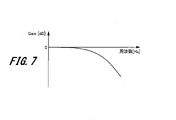
- FIG. 7 shows the frequency characteristics of the hot-wire airflow sensor 12, where the horizontal axis is the frequency [Hz] and the vertical axis is the gain [dB].
- FIG. 8 shows the relationship between voltage and air volume.
- the average air volume at that time is QA.
- the amount of air is QD . That is, the amount of air measured by the hot-wire type airflow sensor 12 has a minus error of (Q A ⁇ Q D ) with respect to the actual amount of air. Due to the frequency characteristics of the hot-wire airflow sensor 12, the higher the frequency, the greater the attenuation of the output voltage waveform, so the negative error increases.
- the hot-wire airflow sensor 12 has the property that the negative error increases not only when the frequency is high, but also when the pulsation is large.
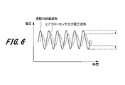
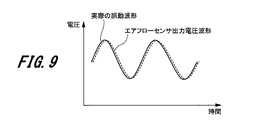
- 9 and 10 show the actual air amount and the output value of the hot wire airflow sensor 12 when the pulsation frequency is the same, FIG. 9 shows a small pulsation, and FIG. 10 shows a large pulsation.
- the hot-wire airflow sensor 12 can follow the actual change in the amount of air.
- the hot-wire airflow sensor 12 cannot follow the actual change in the amount of air, so the output voltage waveform attenuates.
- the output voltage waveform attenuates, resulting in a negative error.
- the hot-wire airflow sensor 12 can predict the pulsation error to some extent from the magnitude of the pulsation and the pulsation frequency.
- a pulsation amplitude ratio (pulsation rate) is used as an index indicating the magnitude of pulsation.
- Fig. 11 shows the tendency of the pulsation error at different frequencies.
- the pulsation error curve has an S-shaped characteristic as shown in FIG. As described above, the higher the frequency, the more the pulsation error becomes negative as a whole. However, since the pulsation error itself can be roughly predicted if the pulsation amplitude ratio and the pulsation frequency are known, the output value of the hot-wire airflow sensor 12 is converted into the air amount by the air amount conversion table 105, and the result is corrected. The effect of pulsation error can be removed.
- FIG. 12 shows an overview of the internal processing when the ECU 100 executes the air amount calculation method using the output signal of the hot wire type air flow sensor 12.
- the intake air amount is calculated from the output of the hot wire type air flow sensor 12 via the A/D converter 104, the sampling means 108, and the air amount conversion table 105, and these constitute the intake air amount calculating means 50. be.
- the internal processing executed by the ECU 100 is expressed as blocks of control functions or arithmetic functions on the drawing.
- This internal processing block receives the output Va from the A/D converter 104 and refers to the A/D conversion value using the sampling means 108 at a sampling timing (for example, 2 ms) which is a first predetermined period. Since this A/D-converted value is attenuated due to the frequency characteristics as described with reference to FIG. Therefore, the current pulsation frequency is calculated from the engine speed 115 using the pulsation frequency calculation means 110, the attenuation amount of the output voltage waveform is predicted from the pulsation frequency, and the frequency response delay correction means 109 corrects the output voltage waveform before attenuation. value.
- the air amount conversion table 205 is used to convert to an air amount.
- the air amount conversion table 205 and the air amount conversion table 105 are the same. However, the air amount conversion table 105 directly converts the voltage value A/D-converted by the sampling means 108 into the air amount, but the air amount conversion table 205 corrects the frequency response delay by the frequency response delay correcting means 109. Since there is a difference that the voltage value of is converted to air volume, it is described separately.
- the air amount converted by the air amount conversion table 205 the air amount for the second period (longer than the first period, for example, 20 ms) is stored and saved by the sampling storage means 111.
- the pulsation amplitude ratio calculation means 112 calculates the pulsation amplitude ratio from the maximum air amount, the minimum air amount, and the average air amount in the second period.
- the pulsation error can be estimated from the pulsation frequency obtained by the pulsation frequency calculation means 110 and the pulsation amplitude ratio obtained by the pulsation amplitude ratio calculation means 112, the pulsation error is calculated by the pulsation error calculation means 113 so as to reduce the pulsation error. to correct.
- the pulsation error calculation means 113 has a pulsation correction map for calculating the pulsation error and correcting it with the air amount correction means 114 .
- the pulsation correction map 130 is shown in FIG.
- the pulsation correction map 130 has axes of pulsation amplitude ratio [%] and pulsation frequency [Hz].
- FIG. 13 shows an example in which the pulsation amplitude ratio is described in increments of 100% and the pulsation frequency is described in increments of 20 Hz, but these intervals can of course be set arbitrarily.
- the pulsation amplitude ratio may be set in increments of 50% or finer, and the pulsation frequency may also be set in increments of 10 Hz or finer.
- the actually detected pulsation amplitude ratio and pulsation frequency are often between these, and in that case, they are obtained by interpolation calculation.
- the pulsation error calculation means 113 refers to the pulsation correction map 130 for the pulsation correction coefficient required to correct the pulsation error based on the pulsation amplitude ratio and the pulsation frequency.
- the pulsation correction map 130 shown in FIG. when the pulsation amplitude ratio is 300%, the pulsation correction map 130 shown in FIG. ”, “1.09” at 100 Hz, and “1.12” at 120 Hz.
- the pulsation frequency is 60 Hz
- the pulsation amplitude ratio is "1” at 0%, “0.99” at 100%, "0.98” at 200%, "1.05" at 300%, and "1.05" at 400%.
- 1.1 500% "1.07", 600% "1.05", 700% "1.02", 800% "0.97", 900% "0.95" , 400%.
- the correction coefficient for the blank spaces has the same tendency as above. is set.
- the pulsation correction coefficient for each pulsation amplitude ratio should be set so that the pulsation error is reduced by the pulsation characteristics of the hot-wire airflow sensor 12 .
- backflow occurs when the pulsation amplitude ratio is 200% or more, but as described above, the hot-wire airflow sensor 12 has a small pulsation error when the pulsation is low, so backflow does not occur.
- the error is small when the pulsation amplitude ratio is 200% or less. Therefore, in the pulsation correction map 130 as well, the pulsation correction coefficient is set to a small value when the pulsation amplitude ratio is 200% or less. In this pulsation correction map 130, the pulsation correction coefficient is set small even when the pulsation amplitude ratio is 800% and 900%, but in this region the pulsation correction coefficient is set based on experiments.
- the air amount correcting the pulsation error is calculated by the air amount correction means 114.
- the air amount correction means 114 multiplies the air amount obtained by directly converting the voltage value A/D-converted by the sampling means 108 by the air amount conversion table 105 by the pulsation correction coefficient referred to by the pulsation error calculation means 113, thereby correcting the pulsation.
- An error-corrected air amount can be calculated.
- FIG. 14 is a block diagram showing a configuration example of an air flow measurement system according to one embodiment of the present invention.
- the air flow measurement system includes an air flow sensor 12A (air flow measurement device) and an ECU 100A (electronic control device). Correct the intake air flow rate.
- the airflow sensor 12A is an airflow measuring device improved to output flow rate data (digital signal) corresponding to the flow rate of the intake air with respect to the airflow sensor 12 described above.
- a sensing unit 1411 , a flow rate acquisition unit 1412 , a pre-stage information acquisition unit 1413 , and an output unit 1414 are provided.
- the airflow sensor 12A has a processor and memory (not shown).
- the processor centrally controls each block of the airflow sensor 12A. For example, a processor and a memory cooperate to implement the function of the pre-stage information acquisition unit 1413 .
- the sensing unit 1411 is composed of a bridge circuit having the above-described heating resistor as a main component, and extracts the current flowing through the heating resistor as a voltage signal (analog signal) according to the intake air flow rate (intake air amount). and outputs a voltage signal to the flow rate acquisition unit 1412 .
- the flow rate acquisition unit 1412 has the same function as the A/D converter 104. That is, the flow rate acquiring section 1412 analog-digital converts the voltage signal of the analog signal input from the sensing section 1411 and outputs the digital signal (flow rate data) to the preceding stage information acquiring section 1413 .
- the preceding stage information acquisition section 1413 acquires information representing the characteristics of the flow rate data (pulsation waveform) input from the flow rate acquisition section 1412, and outputs the information representing the characteristics of the flow rate data to the output section 1414 as the preceding stage information.
- the pre-stage information is information necessary for the ECU 100A to calculate pulsation correction information for correcting the pulsation error of the intake air amount, and is, for example, information about extreme values and inflection points of the pulsation waveform.
- the details of the pre-stage information acquisition unit 1413 will be described later with reference to FIGS. 16 and 17. FIG.
- the output unit 1414 generates a communication signal containing the flow rate data input from the A/D converter 104 and the upstream information input from the upstream information acquisition unit 1413, and transmits the communication signal to the input unit 1421 of the ECU 100A.
- the output section 1414 of the airflow sensor 12A and the input section 1421 of the ECU 100A are each connected according to the SENT (Single Edge Nibble Transmission) communication protocol. That is, output unit 1414 is configured to generate a communication signal according to the SENT communication protocol and output the communication signal to ECU 100A.
- the preceding stage information acquisition section (the preceding stage information acquisition section 1413) has an extreme value calculation function for calculating extreme value information of the air flow rate (flow data) as the preceding stage information, and the output section ( The output unit 1414) is configured to output information on the extreme value to the electronic control unit (ECU 100A) in addition to the air flow rate.
- the pre-stage information acquisition unit (pre-stage information acquisition unit 1413) has an inflection point calculation function for calculating information on the inflection point of the air flow rate (flow data) as the pre-stage information.
- the output unit (output unit 1414) may be configured to output information on the point of inflection in addition to the air flow rate to the electronic control unit (ECU 100A).
- SENT communication is one of the serial communication standards and is a one-way/one-wire communication protocol (SAE J2716).
- SAE J2716 data values are encoded as the time from one falling edge of the signal to the next falling edge.
- a SENT communication can send two types of data values.
- the output unit 1414 transmits flow rate data and pre-stage information on the FAST channel.
- the ECU 100A includes an input section 1421, a pre-stage information processing period calculation section 1422, a pre-stage information processing section 1423, a pulsation error calculation section 1424, and an air amount correction section 1425.
- a CPU 103 in the ECU 100 comprehensively controls each block of the ECU 100A.
- the input unit 1421 performs input processing on a communication signal including flow rate data and pre-stage information input from the airflow sensor 12A. Then, input section 1421 outputs the flow rate data included in the communication signal to air amount correction section 1425 and outputs the preceding information included in the communication signal to preceding information processing section 1423 .
- the input unit 1421 is configured to receive a communication signal from the airflow sensor 12A according to the SENT communication protocol. Note that the input unit 1421 may temporarily store the flow rate data and the pre-stage information included in the communication signal in the memory 103M.
- the preceding information processing period calculation unit 1422 calculates a time corresponding to a predetermined rotation angle (deg) per hour from the output signal (rotational speed information) of the crank angle sensor 25, and defines this time as a preceding information processing period. Output to the processing unit 1423 .
- the preceding information processing period may be a period corresponding to at least one intake stroke, but is preferably a period corresponding to two or more intake strokes. Such a period set for some purpose is also generally called a "window".
- the pre-stage information processing period is determined by the rotation speed of the internal combustion engine 10 and the number of cylinders, but may be determined for each predetermined crank angle. For example, in the case of 3 cylinders as an example determined by the rotational speed and the number of cylinders, the pre-information processing is performed every 240 degrees for a period corresponding to the range of 480 degrees as the pre-information processing period.
- the intake stroke timing can be detected from a reference signal included in the output signal of the crank angle sensor 25, for example, a signal corresponding to missing signal teeth of the crank plate.
- the preceding information processing section 1423 calculates the pulsation correction information for the preceding information processing period inputted from the preceding information processing period calculating section 1422 based on the preceding information of the flow rate data inputted from the input section 1421 .
- the pulsation correction information is information used to correct the pulsation error of the intake air amount (air flow rate). Therefore, the pre-stage information processing section 1423 can be said to be a pulsation correction information calculation section, and can also be said to be a waveform analysis section because it analyzes the flow rate data (pulsation waveform) from the pre-stage information.
- Pre-stage information processing section 1423 calculates pulsation correction information at predetermined timing such as each intake stroke, and outputs the information to pulsation error calculation section 1424 . Details of the pre-stage information processing unit 1423 will be described later with reference to FIG.
- a pulsation error calculation unit 1424 considers the number of revolutions obtained from the crank angle signal of the crank angle sensor 25, calculates the pulsation error of the intake air amount, that is, the pulsation correction coefficient, and outputs it to the air amount correction unit 1425. Details of the pulsation error calculator 1424 will be described later with reference to FIG.
- the air amount correction unit 1425 corrects the flow rate data received from the air flow sensor 12A via the input unit 1421 using the pulsation correction coefficient input from the pulsation error calculation unit 1424, and the pulsation error is corrected (reduced). Air volume information can be obtained.
- the flow rate data (flow rate value) is multiplied by the pulsation correction coefficient to correct the flow rate data, but the present invention is not limited to this.
- a pulsation correction map may be prepared in which correction amounts are registered instead of pulsation correction coefficients, and the correction amounts may be added to flow rate data (flow rate values).
- the correction amount may be added after multiplying the flow rate data (flow rate value) by the correction coefficient.
- FIG. 15 is a block diagram showing a modification of the airflow sensor 12A.
- Airflow sensor 12B shown in FIG. 15 differs from airflow sensor 12A shown in FIG.
- a frequency response delay correction unit 1415 performs frequency response delay correction on the signal waveform after A/D conversion, in the same manner as the frequency response delay correction means 109 shown in FIG. That is, the frequency response delay correction unit 1415 predicts the amount of attenuation due to the frequency response delay of the signal waveform of the flow data output from the flow acquisition unit 1412 based on the current pulsation frequency of the intake air amount, Restores values to their pre-decay values. Then, the signal waveform (flow rate data) subjected to the frequency response delay correction is output to the preceding stage information acquisition section 1413 and the output section 1414 .
- the frequency response delay correction unit 1415 may include a calculation unit that calculates the pulsation frequency from the current intake air amount.
- the example of FIG. 15 is a form in which frequency response delay correction, which requires high-speed processing, is performed in the airflow sensor 12B.
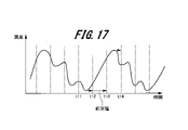
- FIG. 16 is a graph showing an example of the pre-stage information acquisition process by the pre-stage information acquisition unit 1413.
- the horizontal axis indicates time, and the vertical axis indicates flow rate.
- the former stage information acquisition section 1413 holds (stores) the value, and determines the communication timing (for example, the communication cycle 1 ms), the value is transmitted to the ECU 100A.
- the pre-stage information acquisition unit 1413 temporarily stores the detected extreme value in a register or memory in the processor, transmits the value to the ECU 100A, clears it, and updates the next extreme value.
- the memory that stores the extrema can be cache memory or main memory.
- FIG. 16 shows an example in which the maximum value f2 of the flow rate is sampled and held during the period from communication timing t1 to communication timing t2 (sampling and holding period), and the maximum value f2 is transmitted at communication timing t2. Also, the minimum value f3 of the flow rate is held during the communication timing t2 to t3, and the minimum value f3 is transmitted at the communication timing t3. Similarly, the minimum value f4 is transmitted at communication timing t4, the minimum value f5 is transmitted at communication timing t5, and the minimum value f6 is transmitted at communication timing t6.
- the preceding stage information acquiring section acquires the preceding stage information (extreme value) during periodic communication timing (for example, 1 ms).
- the output unit output unit 1414) outputs the preceding information in addition to the air flow rate at the communication timing that comes after the preceding information acquisition unit (previous information acquisition unit 1413) acquires the preceding information. (ECU 100A).
- pre-stage information acquisition processing By executing such pre-stage information acquisition processing, it is possible to transmit pre-stage information (for example, extreme values) of the latest flow rate data (pulsation waveform) from the airflow sensor 12A to the ECU 100A through digital communication.
- pre-stage information for example, extreme values
- the ECU 100A can grasp the order of harmonics of the flow rate data, which will be described later. If the preceding stage information to be transmitted is not the extreme value but information such as a flag indicating whether there is an extreme value or not, the number of bits may be smaller than that for the extreme value.
- the information of the inflection point of the flow rate data may be used instead of the information of the extreme value of the flow rate data as the information of the preceding stage to be transmitted.
- An inflection point is a point where the curvature of the curve of interest (pulsation waveform) changes sign.
- harmonics can be extracted from the information on the inflection points. Wave order can be obtained.
- FIG. 17 is a graph showing an example of an auxiliary function of the preceding stage information acquisition process by the preceding stage information acquisition unit 1413.
- the horizontal axis indicates time, and the vertical axis indicates flow rate.
- This auxiliary function is a function of holding previous-stage information acquired last time until new preceding-stage information is generated, as opposed to the sampling hold function shown in FIG.
- FIG. 17 shows an example in which the minimum value of the flow rate is obtained during the period of communication timings t11 to t12, and the minimum value is transmitted at communication timing t12.
- the extreme value of the flow rate is not detected during the period from the next communication timing t12 to t13, that is, the minimum value is not updated. Therefore, at the communication timing t13, the minimum value (previous value) obtained before the previous communication timing t12 is transmitted. Next, since the maximum value is acquired between communication timings t13 and t14, the maximum value is transmitted at communication timing t14.
- the preceding stage information acquisition section retains the preceding stage information acquired last time when the preceding stage information (extreme value) is not updated.
- the output unit (output unit 1414) at the next communication timing (t13), in addition to the air flow rate, electronically acquires the previous information continuously held by the previous information acquisition unit (previous information acquisition unit 1413). Output to the control device (ECU 100A).
- the ECU 100A can detect the timing at which the pre-stage information of the flow rate data is updated only from changes in the pre-stage information. be.
- FIG. 18 is a graph showing an example of the resonance phenomenon of the intake system of the internal combustion engine 10.
- the intake system of the internal combustion engine 10 has a tubular intake passage 15 as shown in FIG. 1 and has a resonance characteristic.
- This characteristic there is an advantage that the torque of the internal combustion engine 10 can be increased.
- the resonance is used to increase the torque, the pulsation of the intake air increases due to the resonance, and the air flow sensor 12A is in a situation where a pulsation error is likely to occur.
- the vibration source of this resonance is the intake pulsation, which is characterized by being dependent on the speed of the internal combustion engine 10 (engine speed).
- FIG. 18 shows an example of the relationship between the engine speed [rpm] and the amount of intake air.
- the solid line is the graph with resonance
- the dashed line is the graph without resonance.
- the amount of intake air increases and the torque increases.
- FIG. 19 is a graph showing an example of the result of analyzing the resonance phenomenon of the intake system of the internal combustion engine 10.
- FIG. 19 shows the relationship between engine speed [rpm] and pulsation amplitude, intake primary vibration frequency [Hz], and intake primary period (T2) [ms] in order from the top.
- the intake primary vibration frequency is the fundamental frequency of pulsation
- the intake primary period is the reciprocal of the fundamental frequency of pulsation.
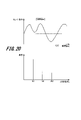
- FIG. 20 is a graph showing an example of an intake pulsation waveform of the internal combustion engine 10 and a frequency analysis result.
- the upper waveform in FIG. 20 is an example of a pulsation waveform when the resonance (engine speed 2400 rpm) in FIG. ) shows the output.
- Frequency analysis of the pulsation waveform in the upper row results in the spectrum in the lower row. Looking at the lower spectrum, it can be seen that the pulsation waveform (fundamental frequency of 80 Hz) includes up to the third harmonic. Also, in order to calculate the pulsation amplitude, it is necessary to store the maximum and minimum values for 12.5 ms and take the difference between them, and it is difficult to calculate the amplitude with the airflow sensor 12A. Recognize. In other words, in order to calculate the pulsation amplitude for 12.5 ms, the airflow sensor 12A needs means for storing the maximum and minimum values for 12.5 ms.
- the accuracy of expressing the waveform of the third harmonic is four times per cycle of the third harmonic. It is considered that the resolution of 4 times per cycle does not provide sufficient information during one cycle and does not provide sufficient accuracy for waveform analysis. Therefore, by performing preliminary information processing on the flow rate data in the airflow sensor 12A during this communication, sufficient accuracy can be obtained for analysis of the pulsation waveform.
- FIG. 21 is a graph showing an example of the intake pulsation waveform of the internal combustion engine 10 and the relationship between control processing.
- This graph shows an analysis example in which the pulsation waveform at an engine speed of 6000 rpm becomes a waveform similar to the pulsation waveform in FIG. 20, based on the same idea as in FIG. T1 represents a communication cycle (for example, 1 ms), and time T2 represents a time corresponding to the first intake cycle (5 ms).
- the pulsation waveform in FIG. 21 has four extreme values (1) to (4) in the first intake cycle at time T2. Also, from the relationship between the communication cycle T1 and the time T2, it can be seen that only five communications can be performed within the time T2 of one combustion cycle. However, by performing the pre-stage information acquisition processing during this communication cycle T1, it becomes possible for the ECU 100A to accurately estimate the pulsation waveform, and it is possible to perform waveform processing at high rotation as well as at low rotation. Recognize.
- the communication cycle T1 between the output section 1414 of the airflow sensor 12A and the input section 1421 of the ECU 100A is sufficiently shorter than the primary intake cycle T2 based on the engine speed. At least, it is desirable that the communication period T1 be a fraction of the pulsation period or less when the engine speed is high.
- FIG. 22 is a graph showing a three-dimensional display example of frequency analysis results of intake pulsations of the internal combustion engine 10.
- FIG. FIG. 22 shows the result of analysis of the relationship between the excitation force due to the intake cycle of the internal combustion engine 10 and the resonance of the intake passage 15 .
- the horizontal axis represents pulsation frequency [Hz]
- the vertical axis represents engine speed [rpm]
- the height of the graph represents pulsation amplitude.
- the pulsation of the intake air resonates with the intake passage 15, maximizing the pulsation amplitude.
- the second harmonic is amplified because the period twice the pulsation period (1/2 frequency) overlaps with the natural frequency of the intake system. Due to such a phenomenon, a complex waveform including harmonics is generated in the output signal of the airflow sensor 12A.
- FIG. 23 is a block diagram showing a configuration example of the pre-stage information processing section 1423 of the ECU 100A.
- the pre-stage information processing section 1423 includes a maximum/minimum value storage section 2311 , a pulsation amplitude calculation section 2312 , an extremum number storage section 2321 and a harmonic detection section 2322 .
- Maximum value/minimum value storage unit 2311 based on the previous information processing period calculated by the previous information processing period calculation unit 1422 and the previous information (extreme value) of the flow data input from the input unit 1421, the period The maximum value and/or minimum value of the flow rate data (pulsation waveform) in the data is obtained and stored in the memory 103M.
- the pulsation amplitude calculation unit 2312 calculates the pulsation amplitude from the maximum and minimum values within the preceding information processing period stored in the maximum/minimum value storage unit 2311 and outputs the pulsation amplitude to the pulsation error calculation unit 1424 .
- the extreme value number storage section 2321 Based on the preceding information processing period calculated by the preceding information processing period calculating section 1422 and the preceding stage information (extreme value) of the flow rate data input from the input section 1421, the extreme value number storage section 2321 The number of extreme values of the flow rate data (pulsation waveform) is obtained and stored in the memory 103M.
- the extreme value number storage unit 2321 stores the number of local minimum values (“( ⁇ ) number of extreme values” in the figure) and the number of local maximum values (“(+) number of extreme values” in the figure) during the preceding information processing period. ) respectively. If the preceding information is not an extreme value but an inflection point, the number of descending inflection points ((-) inflection points) and the number of ascending inflection points ((+) inflection points) are acquired. memorize.
- the harmonic detection unit 2322 detects harmonics based on the number of ( ⁇ ) extrema and the number of (+) extrema in the preceding information processing period stored in the extremum number storage unit 2321 and the harmonics table 2323. Detect features or harmonic orders. Harmonic detector 2322 then outputs the harmonic order to pulsation error calculator 1424 . For example, in the harmonics table 2323, the order of harmonics is defined at the point where the two axes intersect, with the ( ⁇ ) extreme value number and the (+) extreme value number as axes. This harmonic detection is performed in parallel with the pulsation amplitude calculation.
- FIG. 24 is a block diagram showing a configuration example of the pulsation error calculator 1424 of the ECU 100A.
- a pulsation error calculation unit 1424 selects a pulsation correction map from the pulsation correction maps 2400(1) to 2400(n) based on the engine speed, the pulsation amplitude ratio calculated from the pulsation amplitude, and the harmonic order to correct the pulsation. Determine the coefficient.
- the pulsation correction maps 2400(1) to 2400(n) have the same basic configuration as the pulsation correction map 130, and are prepared in advance for each harmonic order and stored in the memory 103M.
- the harmonic order (harmonic waveform) of the flow rate data (pulsation waveform) is detected from the preceding stage information, and the harmonic order is reflected in the pulsation error calculation together with the pulsation amplitude ratio and pulsation frequency.
- a pulsation error coefficient can be calculated.
- the pulsation amplitude ratio may be calculated using the pulsation amplitude ratio calculation means 112 of FIG. 12 instead of the pulsation error calculator 1424. Furthermore, the difference in weather conditions may be reflected in the pulsation correction map.
- the pulsation error may be calculated based on the operating state of the variable valve timing mechanism (the phase of the intake valve 30 and/or the exhaust valve 31) as well as the harmonic order. For example, a pulse rate correction map is created for each combination of harmonic order and valve phase.
- FIG. 25 is a block diagram showing an example of the airflow sensor diagnostic function of the ECU 100A.
- the ECU 100A has a pulsation feature calculation section 2501 and a diagnosis section 2502 .
- the pulsation feature calculation unit calculates pulsation feature information representing the pulsation feature of the corrected air flow rate corrected by the pulsation correction unit (air amount correction unit 1425), and sends the pulsation feature information to the diagnosis unit. (Diagnosis unit 2502).
- the diagnostic unit calculates the air flow rate based on the pulsation feature information of the corrected air flow rate calculated by the pulsation feature information calculation unit (pulsation feature calculation unit 2501) and parameters representing the state of the internal combustion engine 10. Diagnose the measuring device (airflow sensor 12A) and output the diagnosis result.
- the pulsation characteristic information is the pulsation amplitude of the corrected air flow rate
- the parameters representing the state of the internal combustion engine 10 are the rotational speed of the internal combustion engine 10 and the opening of the throttle valve.
- a pulsation amplitude ratio may be used instead of the pulsation amplitude.
- the diagnosis unit 2502 diagnoses that the airflow sensor 12A is abnormal
- the ECU 100A displays the airflow sensor abnormality on the instrument panel or executes fail-safe processing.
- the pulsation error calculator 1424 by correcting the air flow rate (pulsation waveform) measured by the airflow sensor 12A in the pulsation error calculator 1424, the characteristics of the pulsation waveform including harmonics can be reproduced. Therefore, it is possible to highly accurately diagnose the deterioration of the accuracy of the airflow sensor 12A.
- FIG. 26 is a graph showing an example of airflow sensor diagnosis of the ECU 100A.
- FIG. 26 shows an example of diagnosing an abnormality in the airflow sensor 12A based on the highly accurate pulsation amplitude value (or pulsation amplitude ratio) calculated by the air amount correction unit 1425, the engine speed, and the throttle valve opening. ing.
- the pulsation influencing factor such as the variable valve timing mechanism, which can affect the pulsation of the intake air amount is normal. If the airflow sensor 12A is normal, the pulsation is large in the region where the engine speed is low and the throttle valve opening is large, and the pulsation is small in the region where the engine speed is high and the throttle valve opening is small.
- Diagnosis unit 2502 detects that the pulsation of the corrected air flow rate is small despite the region where pulsation is large, or that the pulsation of the corrected air flow rate is large irrespective of the region where pulsation is small. Judged as abnormal. This is useful as a technique using pulsation characteristic parameters (for example, pulsation amplitude or pulsation amplitude ratio) whose accuracy is improved by the present invention.
- pulsation characteristic parameters for example, pulsation amplitude or pulsation amplitude ratio
- the air flow rate measuring device (air flow sensor 12, 12B) according to one embodiment of the present invention provides an output signal (voltage signal) and outputs the air flow rate to the electronic control unit (ECU 100A).
- the air flow rate measuring device (air flow sensor 12, 12B) has a flow rate acquisition section (flow rate acquisition section 1412) that acquires the air flow rate based on the output signal of the sensing section, and based on the air flow rate acquired by the flow rate acquisition section.
- pre-stage information acquisition unit 1413 for acquiring pre-stage information necessary for calculating pulsation correction information (pulsation amplitude, etc.) for the electronic control device to correct the pulsation error of the air flow rate
- An output unit output unit 1414) that outputs the preceding stage information to the electronic control unit (ECU 100A) in addition to the air flow rate.
- the electronic control unit (ECU 100A) is an electronic control unit that controls the internal combustion engine based on the air flow rate taken into the internal combustion engine.
- the electronic control unit (ECU 100A) inputs from the air flow rate measurement device (air flow sensors 12A, 12B) necessary for calculating pulsation correction information (pulsation amplitude, etc.) for correcting the air flow rate pulsation error.
- a pulsation correction information calculation unit (previous information processing unit 1423) that calculates pulsation correction information using the preceding information and the rotational speed of the internal combustion engine obtained from the output signal of the crank angle sensor; 12A, 12B) and a pulsation correction unit (air amount correction unit 1425) that corrects the air flow rate based on the pulsation correction information calculated by the pulsation correction information calculation unit (previous information processing unit 1423); , provided.
- the electronic control unit (ECU 100A) further calculates a processing period (previous information processing period) corresponding to the intake stroke of the internal combustion engine based on the output signal of the crank angle sensor. Harmonics of the pulsation of the intake air are calculated from the calculation unit (processing period calculation unit 1422) and the previous stage information (extreme value or inflection point) input from the air flow rate measuring device (air flow sensor 12A, 12B) during the processing period. and a harmonic detector (harmonic detector 2322) for detection.
- a processing period previously information processing period
- Harmonics of the pulsation of the intake air are calculated from the calculation unit (processing period calculation unit 1422) and the previous stage information (extreme value or inflection point) input from the air flow rate measuring device (air flow sensor 12A, 12B) during the processing period.
- a harmonic detector harmonic detector 2322
- the pulsation correction unit uses the air flow rate input from the air flow rate measurement device (air flow sensors 12A and 12B) and the pulsation correction calculated by the pulsation correction information calculation unit (previous information processing unit 1423).
- the air flow rate is corrected based on the information (pulsation amplitude, etc.) and the harmonic order detected by the harmonic detector (harmonic detector 2322).
- the air flow rate measuring device uses pulsation correction information (for example, pulsation amplitude) for correcting the pulsation error of the air flow rate (pulsation waveform). Instead, it acquires the extreme value or inflection point, which is the information in the previous stage, and outputs it to the electronic control unit (ECU 100A). Therefore, it is possible to reduce the calculation load of the air flow rate measuring device (air flow sensors 12, 12B). Therefore, in the present embodiment, the intake air amount is accurately calculated by correcting the error due to the pulsation of the output signal of the air flow measurement device without increasing the calculation load of the air flow measurement device (air flow sensors 12A and 12B). can do.
- pulsation correction information for example, pulsation amplitude
- the electronic control unit can control the control target such as the internal combustion engine based on the highly accurate intake air amount.
- the control target such as the internal combustion engine
- the electronic control eliminates this problem.
- the electronic control device ECU 100A It is possible to improve the accuracy of information (maximum value, minimum value) necessary for calculating pulsation correction information (pulsation amplitude, etc.) on the side.
- the preceding stage information (extreme value or inflection point) of the flow data is compared with the calculation period of the electronic control unit (ECU 100A) and high frequency sampling (for example, period 1 ms ), the accuracy of the preceding stage information to be acquired is high.
- the electronic control unit (ECU 100A) that can grasp the engine speed and crank angle is not on the side of the air flow measuring device (air flow sensor 12A, 12B) that is difficult to grasp the engine speed and crank angle.
- pulsation correction information (pulsation amplitude, etc.) is calculated on the side. Therefore, it is possible to calculate the pulsation in consideration of the engine speed and crank angle. Therefore, it is possible to distinguish whether the output signal of the air flow measuring device (air flow sensor 12, 12B) is a transient response or a pulsation, or whether it is a pulsation or a harmonic, and the accuracy of the pulsation correction of the air flow measurement system as a whole is improved. do.
- any one of the temperature, humidity, and pressure measured by other sensors may be transmitted to the ECU 100A through the SLOW channel of SENT communication.
- the present invention is not limited to the above-described embodiment, and of course, various other applications and modifications can be made without departing from the gist of the present invention described in the claims.
- the configuration of the air flow rate measuring device (airflow sensors 12A, 12B) and the electronic control unit (ECU 100A) is described in detail and concretely in order to explain the present invention in an easy-to-understand manner. It is not limited to having all the components described. Moreover, it is also possible to add, replace, or delete other components for a part of the configuration of each embodiment.
- each of the above configurations, functions, processing units, etc. may be realized by hardware, for example, by designing a part or all of them with an integrated circuit.
- a broadly defined processor device such as FPGA (Field Programmable Gate Array) or ASIC (Application Specific Integrated Circuit) may be used.
- control lines and information lines indicate those that are considered necessary for explanation, and not all the control lines and information lines are necessarily indicated on the product. In practice, it may be considered that almost all components are interconnected.
Landscapes
- Physics & Mathematics (AREA)
- Fluid Mechanics (AREA)
- General Physics & Mathematics (AREA)
- Measuring Volume Flow (AREA)
Priority Applications (1)
| Application Number | Priority Date | Filing Date | Title |
|---|---|---|---|
| JP2022578035A JPWO2022163006A1 (https=) | 2021-01-26 | 2021-09-17 |
Applications Claiming Priority (2)
| Application Number | Priority Date | Filing Date | Title |
|---|---|---|---|
| JP2021-010542 | 2021-01-26 | ||
| JP2021010542 | 2021-01-26 |
Publications (1)
| Publication Number | Publication Date |
|---|---|
| WO2022163006A1 true WO2022163006A1 (ja) | 2022-08-04 |
Family
ID=82654407
Family Applications (1)
| Application Number | Title | Priority Date | Filing Date |
|---|---|---|---|
| PCT/JP2021/034250 Ceased WO2022163006A1 (ja) | 2021-01-26 | 2021-09-17 | 空気流量計測装置、電子制御装置、及び空気流量計測システム |
Country Status (2)
| Country | Link |
|---|---|
| JP (1) | JPWO2022163006A1 (https=) |
| WO (1) | WO2022163006A1 (https=) |
Cited By (2)
| Publication number | Priority date | Publication date | Assignee | Title |
|---|---|---|---|---|
| CN119749168A (zh) * | 2024-12-30 | 2025-04-04 | 浙江吉利控股集团有限公司 | 车载空调器的控制方法和装置、存储介质、整车控制器 |
| WO2025090031A1 (en) * | 2023-10-24 | 2025-05-01 | Vhs Elektroni̇k Elektri̇k Maki̇na Yazilim Sanayi̇ Ve Ti̇caret Li̇mi̇ted Şi̇rketi̇ | A measuring apparatus |
Citations (3)
| Publication number | Priority date | Publication date | Assignee | Title |
|---|---|---|---|---|
| JP2003505673A (ja) * | 1999-07-17 | 2003-02-12 | ローベルト ボツシユ ゲゼルシヤフト ミツト ベシユレンクテル ハフツング | 脈動する量を検出する装置 |
| JP2003287453A (ja) * | 2002-03-27 | 2003-10-10 | Denso Corp | 吸入空気流量測定装置 |
| JP2019086439A (ja) * | 2017-11-08 | 2019-06-06 | 株式会社デンソー | 空気流量計測装置、及び空気流量計測システム |
-
2021
- 2021-09-17 JP JP2022578035A patent/JPWO2022163006A1/ja active Pending
- 2021-09-17 WO PCT/JP2021/034250 patent/WO2022163006A1/ja not_active Ceased
Patent Citations (3)
| Publication number | Priority date | Publication date | Assignee | Title |
|---|---|---|---|---|
| JP2003505673A (ja) * | 1999-07-17 | 2003-02-12 | ローベルト ボツシユ ゲゼルシヤフト ミツト ベシユレンクテル ハフツング | 脈動する量を検出する装置 |
| JP2003287453A (ja) * | 2002-03-27 | 2003-10-10 | Denso Corp | 吸入空気流量測定装置 |
| JP2019086439A (ja) * | 2017-11-08 | 2019-06-06 | 株式会社デンソー | 空気流量計測装置、及び空気流量計測システム |
Cited By (2)
| Publication number | Priority date | Publication date | Assignee | Title |
|---|---|---|---|---|
| WO2025090031A1 (en) * | 2023-10-24 | 2025-05-01 | Vhs Elektroni̇k Elektri̇k Maki̇na Yazilim Sanayi̇ Ve Ti̇caret Li̇mi̇ted Şi̇rketi̇ | A measuring apparatus |
| CN119749168A (zh) * | 2024-12-30 | 2025-04-04 | 浙江吉利控股集团有限公司 | 车载空调器的控制方法和装置、存储介质、整车控制器 |
Also Published As
| Publication number | Publication date |
|---|---|
| JPWO2022163006A1 (https=) | 2022-08-04 |
Similar Documents
| Publication | Publication Date | Title |
|---|---|---|
| JP4130800B2 (ja) | エンジンの制御装置 | |
| JP5851358B2 (ja) | 内燃機関の制御装置 | |
| JP5107392B2 (ja) | 気筒間の空燃比の不均衡を判断するための装置 | |
| JP4700079B2 (ja) | 気筒間の空燃比の不均衡を判断するための装置 | |
| JP4527792B2 (ja) | 排ガス浄化装置の劣化判定装置 | |
| JP5277349B2 (ja) | 内燃機関の吸気パラメータ算出装置および吸気パラメータ算出方法 | |
| JP5335704B2 (ja) | 気筒間の空燃比の不均衡を判断するための装置 | |
| WO2022163006A1 (ja) | 空気流量計測装置、電子制御装置、及び空気流量計測システム | |
| JP5331613B2 (ja) | 内燃機関の筒内ガス量推定装置 | |
| JP2013160121A (ja) | 内燃機関の空気量計測装置及び空気量計測方法 | |
| JP5639918B2 (ja) | エンジンの吸入空気量測定装置 | |
| JP2004019629A (ja) | 内燃機関の制御装置 | |
| JP2008180225A (ja) | エンジンの制御装置 | |
| US7216639B2 (en) | Abnormality diagnosis device for air-fuel ratio sensor | |
| JP2007211654A (ja) | 内燃機関の空燃比制御装置 | |
| JP5553928B2 (ja) | 気筒間の空燃比の不均衡を判断するための装置 | |
| JP4747977B2 (ja) | 筒内圧センサの校正装置 | |
| JP5372664B2 (ja) | 内燃機関の制御装置 | |
| JP2015190397A (ja) | 内燃機関のスート排出量推定装置 | |
| JP2011252785A (ja) | 内燃機関の吸入空気量補正方法 | |
| JP6636156B2 (ja) | 燃料噴射装置の制御装置 | |
| JP4246461B2 (ja) | 吸入空気量算出装置 | |
| JP4581038B2 (ja) | 内燃機関の燃料噴射量制御装置 | |
| JP2006284533A (ja) | 筒内圧力センサの異常検知装置 | |
| JP4209853B2 (ja) | 内燃機関の制御装置 |
Legal Events
| Date | Code | Title | Description |
|---|---|---|---|
| 121 | Ep: the epo has been informed by wipo that ep was designated in this application |
Ref document number: 21923014 Country of ref document: EP Kind code of ref document: A1 |
|
| ENP | Entry into the national phase |
Ref document number: 2022578035 Country of ref document: JP Kind code of ref document: A |
|
| NENP | Non-entry into the national phase |
Ref country code: DE |
|
| 122 | Ep: pct application non-entry in european phase |
Ref document number: 21923014 Country of ref document: EP Kind code of ref document: A1 |