WO2022163006A1 - 空気流量計測装置、電子制御装置、及び空気流量計測システム - Google Patents
空気流量計測装置、電子制御装置、及び空気流量計測システム Download PDFInfo
- Publication number
- WO2022163006A1 WO2022163006A1 PCT/JP2021/034250 JP2021034250W WO2022163006A1 WO 2022163006 A1 WO2022163006 A1 WO 2022163006A1 JP 2021034250 W JP2021034250 W JP 2021034250W WO 2022163006 A1 WO2022163006 A1 WO 2022163006A1
- Authority
- WO
- WIPO (PCT)
- Prior art keywords
- pulsation
- air flow
- flow rate
- information
- electronic control
- Prior art date
Links
- 238000012937 correction Methods 0.000 claims abstract description 105
- 230000010349 pulsation Effects 0.000 claims description 319
- 238000004364 calculation method Methods 0.000 claims description 67
- 238000002485 combustion reaction Methods 0.000 claims description 64
- 238000004891 communication Methods 0.000 claims description 62
- 238000012545 processing Methods 0.000 claims description 30
- 238000005259 measurement Methods 0.000 claims description 28
- 238000001514 detection method Methods 0.000 claims description 14
- 238000003745 diagnosis Methods 0.000 claims description 12
- 230000000737 periodic effect Effects 0.000 claims description 2
- 230000010365 information processing Effects 0.000 description 33
- 239000000446 fuel Substances 0.000 description 32
- 230000004044 response Effects 0.000 description 22
- 230000006870 function Effects 0.000 description 21
- 238000006243 chemical reaction Methods 0.000 description 20
- 238000000034 method Methods 0.000 description 17
- 238000010438 heat treatment Methods 0.000 description 16
- 238000010586 diagram Methods 0.000 description 15
- 238000005070 sampling Methods 0.000 description 12
- 238000002347 injection Methods 0.000 description 9
- 239000007924 injection Substances 0.000 description 9
- 230000008569 process Effects 0.000 description 8
- 230000002238 attenuated effect Effects 0.000 description 5
- 230000001276 controlling effect Effects 0.000 description 5
- 230000007246 mechanism Effects 0.000 description 5
- 239000003054 catalyst Substances 0.000 description 4
- 230000008859 change Effects 0.000 description 4
- 230000000694 effects Effects 0.000 description 4
- 238000012986 modification Methods 0.000 description 4
- 230000004048 modification Effects 0.000 description 4
- 238000011144 upstream manufacturing Methods 0.000 description 4
- 230000033228 biological regulation Effects 0.000 description 3
- 230000007423 decrease Effects 0.000 description 3
- 239000007789 gas Substances 0.000 description 3
- 230000003434 inspiratory effect Effects 0.000 description 3
- XLYOFNOQVPJJNP-UHFFFAOYSA-N water Substances O XLYOFNOQVPJJNP-UHFFFAOYSA-N 0.000 description 3
- KDLHZDBZIXYQEI-UHFFFAOYSA-N Palladium Chemical compound [Pd] KDLHZDBZIXYQEI-UHFFFAOYSA-N 0.000 description 2
- 230000002159 abnormal effect Effects 0.000 description 2
- 230000005856 abnormality Effects 0.000 description 2
- 230000008901 benefit Effects 0.000 description 2
- 239000002828 fuel tank Substances 0.000 description 2
- BASFCYQUMIYNBI-UHFFFAOYSA-N platinum Chemical compound [Pt] BASFCYQUMIYNBI-UHFFFAOYSA-N 0.000 description 2
- 238000001228 spectrum Methods 0.000 description 2
- 230000001052 transient effect Effects 0.000 description 2
- PNEYBMLMFCGWSK-UHFFFAOYSA-N aluminium oxide Inorganic materials [O-2].[O-2].[O-2].[Al+3].[Al+3] PNEYBMLMFCGWSK-UHFFFAOYSA-N 0.000 description 1
- 230000001174 ascending effect Effects 0.000 description 1
- QVGXLLKOCUKJST-UHFFFAOYSA-N atomic oxygen Chemical compound [O] QVGXLLKOCUKJST-UHFFFAOYSA-N 0.000 description 1
- 230000005540 biological transmission Effects 0.000 description 1
- CETPSERCERDGAM-UHFFFAOYSA-N ceric oxide Chemical compound O=[Ce]=O CETPSERCERDGAM-UHFFFAOYSA-N 0.000 description 1
- 229910000422 cerium(IV) oxide Inorganic materials 0.000 description 1
- 230000009194 climbing Effects 0.000 description 1
- 239000011248 coating agent Substances 0.000 description 1
- 238000000576 coating method Methods 0.000 description 1
- 239000000470 constituent Substances 0.000 description 1
- 238000007796 conventional method Methods 0.000 description 1
- 239000000498 cooling water Substances 0.000 description 1
- 230000001419 dependent effect Effects 0.000 description 1
- 230000006866 deterioration Effects 0.000 description 1
- 238000011161 development Methods 0.000 description 1
- 230000018109 developmental process Effects 0.000 description 1
- 230000005284 excitation Effects 0.000 description 1
- 238000002474 experimental method Methods 0.000 description 1
- 239000000284 extract Substances 0.000 description 1
- 238000001914 filtration Methods 0.000 description 1
- 238000009499 grossing Methods 0.000 description 1
- 230000014759 maintenance of location Effects 0.000 description 1
- 239000000203 mixture Substances 0.000 description 1
- 239000001301 oxygen Substances 0.000 description 1
- 229910052760 oxygen Inorganic materials 0.000 description 1
- 229910052763 palladium Inorganic materials 0.000 description 1
- 229910052697 platinum Inorganic materials 0.000 description 1
- 239000012041 precatalyst Substances 0.000 description 1
- 238000012889 quartic function Methods 0.000 description 1
- 230000001105 regulatory effect Effects 0.000 description 1
- 230000000717 retained effect Effects 0.000 description 1
- 239000004065 semiconductor Substances 0.000 description 1
- 239000007858 starting material Substances 0.000 description 1
- 238000009423 ventilation Methods 0.000 description 1
Images


Classifications
-
- G—PHYSICS
- G01—MEASURING; TESTING
- G01F—MEASURING VOLUME, VOLUME FLOW, MASS FLOW OR LIQUID LEVEL; METERING BY VOLUME
- G01F1/00—Measuring the volume flow or mass flow of fluid or fluent solid material wherein the fluid passes through a meter in a continuous flow
- G01F1/68—Measuring the volume flow or mass flow of fluid or fluent solid material wherein the fluid passes through a meter in a continuous flow by using thermal effects
-
- G—PHYSICS
- G01—MEASURING; TESTING
- G01F—MEASURING VOLUME, VOLUME FLOW, MASS FLOW OR LIQUID LEVEL; METERING BY VOLUME
- G01F1/00—Measuring the volume flow or mass flow of fluid or fluent solid material wherein the fluid passes through a meter in a continuous flow
- G01F1/72—Devices for measuring pulsing fluid flows
Definitions
- the present invention relates to an air flow measurement device, an electronic control device, and an air flow measurement system.
- the amount of intake air is a parameter used to calculate the amount of fuel injection, and highly accurate detection of the amount of intake air is essential in order to comply with regulations that will become stricter in the future. Since the output result of the airflow sensor influences the fuel consumption and exhaust performance, technical developments are actively being made to improve the detection accuracy of the intake air amount of the airflow sensor.
- a hot wire type airflow sensor is currently widely used as an airflow sensor that can measure the amount of intake air, and the detection signal of this airflow sensor changes the voltage value according to the amount of air based on the signal from the heating resistor.
- Others use a voltage signal or a frequency signal that changes the period of the output pulse depending on the amount of air.
- the reciprocating motion of the piston in an internal combustion engine causes intake pulsation in the intake pipe. Occur.
- Patent Document 1 proposes a method of correcting the air amount with respect to the intake pulsation.
- Patent Document 2 a method as described in Patent Document 2 is disclosed for the problem of increased communication load when information is transmitted between the airflow sensor and the control device by communication.
- a flow rate acquisition unit that acquires the air flow rate based on the air flow rate output, and a pulsation error that is an error in the air flow rate due to air pulsation is corrected based on the air flow rate acquired by the flow rate acquisition section.
- an output unit for outputting the pulsation correction information to an electronic device in addition to the air flow rate.
- the method of correcting the intake air amount described in Patent Document 1 is a method of calculating the correction amount based on the intake pipe pressure, the manipulated variable of the throttle valve, or the engine speed when calculating the pulsation amplitude ratio of the intake air. be.
- the method described in Patent Document 2 obtains pulsation correction information in the airflow sensor and transmits it to the control device via communication in order to reduce the communication load when communicating between the airflow sensor and the control device. It is a way to In this method, since the pulsation correction information is acquired by the airflow sensor, the advantage is that high-speed sampling is possible. In addition, since the airflow sensor does not have engine angle information, it is unclear how long the information used for pulsation calculation should be retained, and there is a problem that it is difficult to calculate the amplitude when the pulsation waveform includes harmonics. be. In particular, when the engine is in a low speed range, there is concern that the retention period of information used for pulsation calculation will be long.
- Patent Document 2 the pulsation is calculated within the airflow sensor.
- the pulsation waveform differs depending on the operating conditions of the engine. Therefore, an advanced estimation technique is required to calculate the pulsation with high accuracy. Also, during transient operating conditions, it is necessary to separate fluctuations and pulsations due to transients.
- the current value flowing through the heating resistor placed in the intake air flow to be measured increases when the amount of intake air is large, and conversely decreases when the amount of intake air is small.
- a bridge circuit is configured to Then, an air amount signal is extracted from the current flowing through the heating resistor.
- the hot wire airflow sensor uses the heat balance of the heating resistor, the detection accuracy is affected by the magnitude and frequency of the intake air pulsation, and the output of the hot wire airflow sensor is particularly high. It has a frequency response characteristic in which response delay occurs in the frequency domain. Therefore, when the output characteristic has a non-linear characteristic, the detected output average value and the true air amount average value do not match, and an error occurs. Also, this error tends to increase as the pulsation increases and the frequency increases.
- an air flow measuring device of one aspect of the present invention measures an air flow rate based on an output signal from a sensing unit arranged in an environment where air flows, and outputs the air flow rate to an electronic control device. It is something to do.
- This air flow measurement device includes a flow rate acquisition unit that acquires the air flow rate based on the output signal, and the electronic control device that corrects the pulsation error of the air flow rate based on the air flow rate acquired by the flow rate acquisition section.
- a pre-stage information acquisition unit that acquires pre-stage information necessary to calculate pulsation correction information for the air flow rate, and an output unit that outputs the pre-stage information to the electronic control device in addition to the air flow rate.
- the electronic control device of one aspect of the present invention controls the internal combustion engine based on the flow rate of air taken into the internal combustion engine.
- This electronic control unit is provided with information necessary for calculating pulsation correction information for correcting the pulsation error of the air flow rate.
- a pulsation correction information calculation unit that calculates pulsation correction information using the number of revolutions of the engine, an air flow rate input from the air flow measurement device, and the air flow rate based on the pulsation correction information calculated by the pulsation correction information calculation unit. and a pulsation corrector for correcting.
- An air flow measurement system of one aspect of the present invention includes the air flow measurement device and the electronic control device.
- the controlled object such as the internal combustion engine can be controlled based on the highly accurate intake air amount.
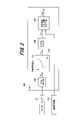
- FIG. 1 is a schematic configuration diagram showing an example of the overall configuration of an internal combustion engine
- FIG. 1 is an overall configuration diagram of an ECU (electronic control unit)
- FIG. 4 is a block diagram showing a general fuel injection pulse width calculation method
- 4 is a graph showing the relationship between the voltage of the airflow sensor and the amount of air
- Fig. 3 is a graph showing the frequency response (low frequency) of an airflow sensor
- Fig. 3 is a graph showing the frequency response (high frequency) of an airflow sensor
- 5 is a graph showing attenuation of frequency characteristics of an airflow sensor
- Fig. 3 is a graph showing the effect of voltage signal attenuation on average air content
- FIG. 3 is a graph showing the frequency response (small pulsation) of the airflow sensor;
- FIG. 4 is a graph showing the frequency response (great pulsation) of the airflow sensor;
- FIG. 7 is a graph showing the tendency of pulsation errors due to different frequencies;
- FIG. 10 is a block diagram showing intake air amount calculation by conventional pulsation error calculation; It is a figure which shows a pulsation correction map.
- 1 is a block diagram showing an example configuration of an air flow measurement system according to an embodiment of the present invention;
- FIG. 4 is a block diagram showing a configuration example of a pulsation error calculator of an ECU;
- FIG. 4 is a block diagram showing an example of an airflow sensor diagnostic function of an ECU;
- 4 is a graph showing an example of ECU airflow sensor diagnosis;
- FIG. 1 is a schematic configuration diagram showing an example of the overall configuration of an internal combustion engine to which a flow rate measuring system according to an embodiment of the invention is applied.
- the internal combustion engine 10 shown in FIG. 1 is, for example, a spark ignition multi-cylinder engine having four cylinders.
- the internal combustion engine 10 includes a cylinder 29 composed of a cylinder head 29a and a cylinder block 29b, and a piston 27 slidably inserted into each cylinder of the cylinder 29.
- Piston 27 is connected to a crankshaft (not shown) via connecting rod 28 .
- a combustion chamber 26 having a ceiling portion of a predetermined shape is defined above the piston 27 .
- An ignition plug 19 to which a high-voltage ignition signal is supplied from the ignition coil 20 is installed in the combustion chamber 26 of each cylinder.
- the combustion chamber 26 also communicates with an intake passage 15 including an air cleaner 11, a throttle valve 13, a collector 16, an intake manifold 17, an intake port 18, and the like. Air necessary for fuel combustion passes through the intake passage 15 and passes through an intake valve 30 driven to open and close by an intake camshaft 22 disposed at the end of an intake port 18, which is the downstream end of the intake passage 15. , and is drawn into the combustion chamber 26 of each cylinder.
- an injector 21 for injecting fuel toward an intake port 18 is provided on the intake manifold 17 of the intake passage 15 for each cylinder.
- an air flow sensor 12 that detects the amount of intake air is arranged downstream of the air cleaner 11 in the intake passage 15 .
- a mixture of air sucked through the intake passage 15 and fuel injected from the injector 21 is sucked into the combustion chamber 26 through the intake valve 30 and spark-ignited by the spark plug 19 connected to the ignition coil 20.
- burned by Exhaust gas after combustion in the combustion chamber 26 is exhausted from the combustion chamber 26 through an exhaust valve 31 that is driven to open and close by an exhaust camshaft 23, and passes through an exhaust port, an exhaust manifold, an exhaust pipe, etc. (not shown). It is configured to be discharged to the outside atmosphere through an exhaust passage 32 provided.
- a three-way catalyst 35 for purifying exhaust gas which is made by coating a carrier such as alumina or ceria with platinum or palladium, is arranged.
- An air-fuel ratio sensor 33 having a linear output characteristic with respect to the pre-catalyst air-fuel ratio is arranged upstream of the three-way catalyst 35 .
- an O2 sensor 34 is arranged for outputting a switching signal for identifying whether the post-catalyst air-fuel ratio is richer or leaner than the stoichiometric (theoretical air-fuel ratio).
- the injector 21 provided for each cylinder of the internal combustion engine 10 is connected to the fuel tank 36 .
- Fuel in the fuel tank 36 is regulated to a predetermined fuel pressure by a fuel supply mechanism including a fuel pump 37 and a fuel pressure regulator 38 and is supplied to the injector 21 .
- the injector 21 supplied with fuel at a predetermined fuel pressure receives a fuel injection pulse signal having a duty (pulse width: corresponding to the valve opening time) according to the operating state such as the engine load supplied from the ECU (Engine Control Unit) 100. is driven to open the valve.
- the injector 21 is configured to inject an amount of fuel corresponding to the valve opening time toward the intake port 18 .
- the ECU 100 incorporates a microcomputer for performing various controls of the internal combustion engine 10, such as fuel injection control (air-fuel ratio control) by the injector 21, ignition timing control by the spark plug 19, and the like.
- fuel injection control air-fuel ratio control
- ignition timing control by the spark plug 19, and the like.
- FIG. 2 shows the overall configuration of the ECU 100.
- the ECU 100 is an example of an electronic control device, and includes a power supply IC 101 and an LSI 102 .
- a RESET terminal (not shown) of the LSI 102 is connected to the power supply IC 101 so that a RESET signal controlled by the power supply IC 101 can be transmitted.
- the ECU 100 also includes sensors necessary for controlling the internal combustion engine 10, such as a crank angle sensor 25 for detecting the engine speed, a water temperature sensor 40 for detecting the temperature of the cooling water of the internal combustion engine 10, a throttle valve opening Signals from the throttle sensor 14 for detecting the engine speed, the air-fuel ratio sensor 33 for detecting the oxygen concentration in the exhaust gas, the starter switch 41, the air flow sensor 12, etc. are input.
- sensors necessary for controlling the internal combustion engine 10 such as a crank angle sensor 25 for detecting the engine speed, a water temperature sensor 40 for detecting the temperature of the cooling water of the internal combustion engine 10, a throttle valve opening Signals from the throttle sensor 14 for detecting the engine speed, the air-fuel ratio sensor 33 for detecting the oxygen concentration in the exhaust gas, the starter switch 41, the air flow sensor 12, etc.
- Detection signals from these sensors are input to an LSI (input processing circuit) 102 in the ECU 100, and divided into those detected by an A/D converter as analog inputs and those detected at High/Low levels. It is processed.
- LSI input processing circuit
- the CPU 103 executes predetermined digital arithmetic processing according to a program stored in the memory 103M in the LSI 102.
- the CPU 103 has a function of outputting control signals for various actuators necessary for controlling the internal combustion engine 10 based on the calculation results and controlling the various actuators via the output circuit of the LSI 102 .
- the memory 103M is composed of a non-volatile or volatile semiconductor memory, and stores parameters, variables generated during arithmetic processing, a pulsation correction map, a harmonic table, etc., which will be described later.
- the CPU 103 controls the mass flow rate measured from the detection signal of the hot wire airflow sensor 12, the rotation speed of the internal combustion engine 10 measured from the crank angle sensor 25, and the water temperature sensor 40. Each correction amount including the water temperature and a correction amount according to the air-fuel ratio state detected by the air-fuel ratio sensor 33 are added to calculate the fuel injection amount. Then, the CPU 103 outputs a control signal as a drive pulse width to each injector 21 of the internal combustion engine 10 based on the fuel injection amount calculated for each injector 21 . Similarly, the CPU 103 outputs an ignition signal for controlling the energization timing of the ignition coil 20 necessary for combustion of the internal combustion engine 10, a control signal for an electronically controlled throttle (not shown) for controlling the opening of the throttle valve, and the like.
- the hot-wire airflow sensor 12 has, as a main component, a heating resistor placed in the airflow to be measured.
- the hot-wire airflow sensor 12 has a bridge circuit configured so that the current value flowing through the heating resistor increases when the amount of intake air is large, and conversely decreases when the amount of intake air is small.
- a reference numeral 12 takes out the amount of air as a voltage signal based on the current flowing through the heating resistor.
- the voltage signal corresponding to the amount of air is output as a voltage value, and may also be converted to a frequency signal by a voltage-frequency conversion circuit and output.
- the flow rate data is transmitted from the air flow sensor 12 to the ECU 100 using digital communication.
- the air flow sensor 12 outputs the measurement result as a voltage (analog signal) will be explained.
- FIG. 3 shows a calculation method for determining the amount of air based on the output signal of a general hot-wire airflow sensor 12, and this calculation is executed by internal processing of the ECU 100.
- the digital value is 200 when 1.0 V is A/D converted.
- the voltage information Va output from the A/D converter 104 is given to the air amount conversion table 105 .
- the air amount conversion table 105 has pre-stored air amounts corresponding to the voltage information Va.
- the voltage information Va is searched and interpolated by the air amount conversion table 105 and converted into the detected air amount.
- the detected air amount will be described as indicating the air amount converted by the air amount conversion table 105 .
- a frequency signal converted from voltage to frequency is input from the air flow sensor 12 to the ECU 100
- the period of the signal is measured at the port input of the CPU 103, and the period or the period is converted to the frequency.
- the values are input to the air amount conversion table 105 .
- the period or the value converted from the period to the frequency is searched and interpolated from the pre-stored value according to the period or frequency in the air amount conversion table 105 and converted to the detected air amount.
- the air quantity signal Q obtained from the air quantity conversion table 105 is then subjected to digital filtering 106 for the purpose of removing high frequency component noise to calculate the detected air quantity Qc.
- the fuel injection pulse width calculating means 107 divides the detected air amount Qc by the rotational speed of the internal combustion engine 10 (hereinafter referred to as "engine rotational speed") 115 separately calculated from the signal of the crank angle sensor 25 to obtain the air intake to the cylinder 29. Convert to quantity equivalent. Further, after the correction calculations described above are performed, the fuel injection pulse width calculation means 107 calculates the time Tout for injecting fuel, and the injector 21 operates to supply the fuel to the internal combustion engine 10 .
- FIG. 4 shows the relationship between the amount of intake air and the output signal of a general hot-wire airflow sensor 12.
- FIG. 4 shows an example of characteristic curves having a nonlinear relationship in which the voltage of the output signal is low when the amount of intake air is small, and the voltage of the signal is high when the amount of intake air is large.
- the nonlinear characteristic is used because the following equation, called King's equation, is mainly used for the amount of air Q when converting the detection signal from the heating resistor into the amount of air.
- Ih ⁇ Rh ( ⁇ + ⁇ ⁇ ⁇ Q) ⁇ (Th - Ta)
- Ih is the current value of the heating resistor
- Rh is the resistance value of the heating resistor
- Th is the surface temperature of the heating resistor
- Ta is the air temperature
- Q is the air volume
- ⁇ and ⁇ are constants determined by the specifications of the heating resistor. is.
- the current value Ih of the heating resistor is controlled so that (Th ⁇ Ta) is constant, so the amount of air is detected by converting it into a voltage value V due to the voltage drop across the resistor.
- the value V becomes a quartic function expression. For this reason, when converting to an air amount, the curvature of the quartic curve, that is, the relationship between the output and the air amount becomes non-linear.
- the output of the hot-wire airflow sensor 12 is set according to the required air amount of the internal combustion engine 10 . Therefore, there are cases where the relationship between the frequency and the air amount or between the voltage and the air amount has an opposite characteristic or a linear relationship, but only the air amount conversion table 105 changes for the arithmetic processing.
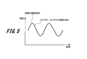
- FIG. 5 shows changes in the actual amount of air and output values of the hot-wire airflow sensor 12 when the pulsation frequency is low. When the pulsation frequency is low, the output of the hot-wire airflow sensor 12 can follow changes in the actual amount of air with little delay.
- FIG. 7 shows the frequency characteristics of the hot-wire airflow sensor 12, where the horizontal axis is the frequency [Hz] and the vertical axis is the gain [dB].
- FIG. 8 shows the relationship between voltage and air volume.
- the average air volume at that time is QA.
- the amount of air is QD . That is, the amount of air measured by the hot-wire type airflow sensor 12 has a minus error of (Q A ⁇ Q D ) with respect to the actual amount of air. Due to the frequency characteristics of the hot-wire airflow sensor 12, the higher the frequency, the greater the attenuation of the output voltage waveform, so the negative error increases.
- the hot-wire airflow sensor 12 has the property that the negative error increases not only when the frequency is high, but also when the pulsation is large.
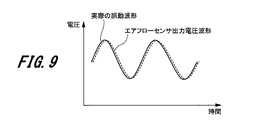
- 9 and 10 show the actual air amount and the output value of the hot wire airflow sensor 12 when the pulsation frequency is the same, FIG. 9 shows a small pulsation, and FIG. 10 shows a large pulsation.
- the hot-wire airflow sensor 12 can follow the actual change in the amount of air.
- the hot-wire airflow sensor 12 cannot follow the actual change in the amount of air, so the output voltage waveform attenuates.
- the output voltage waveform attenuates, resulting in a negative error.
- the hot-wire airflow sensor 12 can predict the pulsation error to some extent from the magnitude of the pulsation and the pulsation frequency.
- a pulsation amplitude ratio (pulsation rate) is used as an index indicating the magnitude of pulsation.
- Fig. 11 shows the tendency of the pulsation error at different frequencies.
- the pulsation error curve has an S-shaped characteristic as shown in FIG. As described above, the higher the frequency, the more the pulsation error becomes negative as a whole. However, since the pulsation error itself can be roughly predicted if the pulsation amplitude ratio and the pulsation frequency are known, the output value of the hot-wire airflow sensor 12 is converted into the air amount by the air amount conversion table 105, and the result is corrected. The effect of pulsation error can be removed.
- FIG. 12 shows an overview of the internal processing when the ECU 100 executes the air amount calculation method using the output signal of the hot wire type air flow sensor 12.
- the intake air amount is calculated from the output of the hot wire type air flow sensor 12 via the A/D converter 104, the sampling means 108, and the air amount conversion table 105, and these constitute the intake air amount calculating means 50. be.
- the internal processing executed by the ECU 100 is expressed as blocks of control functions or arithmetic functions on the drawing.
- This internal processing block receives the output Va from the A/D converter 104 and refers to the A/D conversion value using the sampling means 108 at a sampling timing (for example, 2 ms) which is a first predetermined period. Since this A/D-converted value is attenuated due to the frequency characteristics as described with reference to FIG. Therefore, the current pulsation frequency is calculated from the engine speed 115 using the pulsation frequency calculation means 110, the attenuation amount of the output voltage waveform is predicted from the pulsation frequency, and the frequency response delay correction means 109 corrects the output voltage waveform before attenuation. value.
- the air amount conversion table 205 is used to convert to an air amount.
- the air amount conversion table 205 and the air amount conversion table 105 are the same. However, the air amount conversion table 105 directly converts the voltage value A/D-converted by the sampling means 108 into the air amount, but the air amount conversion table 205 corrects the frequency response delay by the frequency response delay correcting means 109. Since there is a difference that the voltage value of is converted to air volume, it is described separately.
- the air amount converted by the air amount conversion table 205 the air amount for the second period (longer than the first period, for example, 20 ms) is stored and saved by the sampling storage means 111.
- the pulsation amplitude ratio calculation means 112 calculates the pulsation amplitude ratio from the maximum air amount, the minimum air amount, and the average air amount in the second period.
- the pulsation error can be estimated from the pulsation frequency obtained by the pulsation frequency calculation means 110 and the pulsation amplitude ratio obtained by the pulsation amplitude ratio calculation means 112, the pulsation error is calculated by the pulsation error calculation means 113 so as to reduce the pulsation error. to correct.
- the pulsation error calculation means 113 has a pulsation correction map for calculating the pulsation error and correcting it with the air amount correction means 114 .
- the pulsation correction map 130 is shown in FIG.
- the pulsation correction map 130 has axes of pulsation amplitude ratio [%] and pulsation frequency [Hz].
- FIG. 13 shows an example in which the pulsation amplitude ratio is described in increments of 100% and the pulsation frequency is described in increments of 20 Hz, but these intervals can of course be set arbitrarily.
- the pulsation amplitude ratio may be set in increments of 50% or finer, and the pulsation frequency may also be set in increments of 10 Hz or finer.
- the actually detected pulsation amplitude ratio and pulsation frequency are often between these, and in that case, they are obtained by interpolation calculation.
- the pulsation error calculation means 113 refers to the pulsation correction map 130 for the pulsation correction coefficient required to correct the pulsation error based on the pulsation amplitude ratio and the pulsation frequency.
- the pulsation correction map 130 shown in FIG. when the pulsation amplitude ratio is 300%, the pulsation correction map 130 shown in FIG. ”, “1.09” at 100 Hz, and “1.12” at 120 Hz.
- the pulsation frequency is 60 Hz
- the pulsation amplitude ratio is "1” at 0%, “0.99” at 100%, "0.98” at 200%, "1.05" at 300%, and "1.05" at 400%.
- 1.1 500% "1.07", 600% "1.05", 700% "1.02", 800% "0.97", 900% "0.95" , 400%.
- the correction coefficient for the blank spaces has the same tendency as above. is set.
- the pulsation correction coefficient for each pulsation amplitude ratio should be set so that the pulsation error is reduced by the pulsation characteristics of the hot-wire airflow sensor 12 .
- backflow occurs when the pulsation amplitude ratio is 200% or more, but as described above, the hot-wire airflow sensor 12 has a small pulsation error when the pulsation is low, so backflow does not occur.
- the error is small when the pulsation amplitude ratio is 200% or less. Therefore, in the pulsation correction map 130 as well, the pulsation correction coefficient is set to a small value when the pulsation amplitude ratio is 200% or less. In this pulsation correction map 130, the pulsation correction coefficient is set small even when the pulsation amplitude ratio is 800% and 900%, but in this region the pulsation correction coefficient is set based on experiments.
- the air amount correcting the pulsation error is calculated by the air amount correction means 114.
- the air amount correction means 114 multiplies the air amount obtained by directly converting the voltage value A/D-converted by the sampling means 108 by the air amount conversion table 105 by the pulsation correction coefficient referred to by the pulsation error calculation means 113, thereby correcting the pulsation.
- An error-corrected air amount can be calculated.
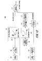
- FIG. 14 is a block diagram showing a configuration example of an air flow measurement system according to one embodiment of the present invention.
- the air flow measurement system includes an air flow sensor 12A (air flow measurement device) and an ECU 100A (electronic control device). Correct the intake air flow rate.
- the airflow sensor 12A is an airflow measuring device improved to output flow rate data (digital signal) corresponding to the flow rate of the intake air with respect to the airflow sensor 12 described above.
- a sensing unit 1411 , a flow rate acquisition unit 1412 , a pre-stage information acquisition unit 1413 , and an output unit 1414 are provided.
- the airflow sensor 12A has a processor and memory (not shown).
- the processor centrally controls each block of the airflow sensor 12A. For example, a processor and a memory cooperate to implement the function of the pre-stage information acquisition unit 1413 .
- the sensing unit 1411 is composed of a bridge circuit having the above-described heating resistor as a main component, and extracts the current flowing through the heating resistor as a voltage signal (analog signal) according to the intake air flow rate (intake air amount). and outputs a voltage signal to the flow rate acquisition unit 1412 .
- the flow rate acquisition unit 1412 has the same function as the A/D converter 104. That is, the flow rate acquiring section 1412 analog-digital converts the voltage signal of the analog signal input from the sensing section 1411 and outputs the digital signal (flow rate data) to the preceding stage information acquiring section 1413 .
- the preceding stage information acquisition section 1413 acquires information representing the characteristics of the flow rate data (pulsation waveform) input from the flow rate acquisition section 1412, and outputs the information representing the characteristics of the flow rate data to the output section 1414 as the preceding stage information.
- the pre-stage information is information necessary for the ECU 100A to calculate pulsation correction information for correcting the pulsation error of the intake air amount, and is, for example, information about extreme values and inflection points of the pulsation waveform.
- the details of the pre-stage information acquisition unit 1413 will be described later with reference to FIGS. 16 and 17. FIG.
- the output unit 1414 generates a communication signal containing the flow rate data input from the A/D converter 104 and the upstream information input from the upstream information acquisition unit 1413, and transmits the communication signal to the input unit 1421 of the ECU 100A.
- the output section 1414 of the airflow sensor 12A and the input section 1421 of the ECU 100A are each connected according to the SENT (Single Edge Nibble Transmission) communication protocol. That is, output unit 1414 is configured to generate a communication signal according to the SENT communication protocol and output the communication signal to ECU 100A.
- the preceding stage information acquisition section (the preceding stage information acquisition section 1413) has an extreme value calculation function for calculating extreme value information of the air flow rate (flow data) as the preceding stage information, and the output section ( The output unit 1414) is configured to output information on the extreme value to the electronic control unit (ECU 100A) in addition to the air flow rate.
- the pre-stage information acquisition unit (pre-stage information acquisition unit 1413) has an inflection point calculation function for calculating information on the inflection point of the air flow rate (flow data) as the pre-stage information.
- the output unit (output unit 1414) may be configured to output information on the point of inflection in addition to the air flow rate to the electronic control unit (ECU 100A).
- SENT communication is one of the serial communication standards and is a one-way/one-wire communication protocol (SAE J2716).
- SAE J2716 data values are encoded as the time from one falling edge of the signal to the next falling edge.
- a SENT communication can send two types of data values.
- the output unit 1414 transmits flow rate data and pre-stage information on the FAST channel.
- the ECU 100A includes an input section 1421, a pre-stage information processing period calculation section 1422, a pre-stage information processing section 1423, a pulsation error calculation section 1424, and an air amount correction section 1425.
- a CPU 103 in the ECU 100 comprehensively controls each block of the ECU 100A.
- the input unit 1421 performs input processing on a communication signal including flow rate data and pre-stage information input from the airflow sensor 12A. Then, input section 1421 outputs the flow rate data included in the communication signal to air amount correction section 1425 and outputs the preceding information included in the communication signal to preceding information processing section 1423 .
- the input unit 1421 is configured to receive a communication signal from the airflow sensor 12A according to the SENT communication protocol. Note that the input unit 1421 may temporarily store the flow rate data and the pre-stage information included in the communication signal in the memory 103M.
- the preceding information processing period calculation unit 1422 calculates a time corresponding to a predetermined rotation angle (deg) per hour from the output signal (rotational speed information) of the crank angle sensor 25, and defines this time as a preceding information processing period. Output to the processing unit 1423 .
- the preceding information processing period may be a period corresponding to at least one intake stroke, but is preferably a period corresponding to two or more intake strokes. Such a period set for some purpose is also generally called a "window".
- the pre-stage information processing period is determined by the rotation speed of the internal combustion engine 10 and the number of cylinders, but may be determined for each predetermined crank angle. For example, in the case of 3 cylinders as an example determined by the rotational speed and the number of cylinders, the pre-information processing is performed every 240 degrees for a period corresponding to the range of 480 degrees as the pre-information processing period.
- the intake stroke timing can be detected from a reference signal included in the output signal of the crank angle sensor 25, for example, a signal corresponding to missing signal teeth of the crank plate.
- the preceding information processing section 1423 calculates the pulsation correction information for the preceding information processing period inputted from the preceding information processing period calculating section 1422 based on the preceding information of the flow rate data inputted from the input section 1421 .
- the pulsation correction information is information used to correct the pulsation error of the intake air amount (air flow rate). Therefore, the pre-stage information processing section 1423 can be said to be a pulsation correction information calculation section, and can also be said to be a waveform analysis section because it analyzes the flow rate data (pulsation waveform) from the pre-stage information.
- Pre-stage information processing section 1423 calculates pulsation correction information at predetermined timing such as each intake stroke, and outputs the information to pulsation error calculation section 1424 . Details of the pre-stage information processing unit 1423 will be described later with reference to FIG.
- a pulsation error calculation unit 1424 considers the number of revolutions obtained from the crank angle signal of the crank angle sensor 25, calculates the pulsation error of the intake air amount, that is, the pulsation correction coefficient, and outputs it to the air amount correction unit 1425. Details of the pulsation error calculator 1424 will be described later with reference to FIG.
- the air amount correction unit 1425 corrects the flow rate data received from the air flow sensor 12A via the input unit 1421 using the pulsation correction coefficient input from the pulsation error calculation unit 1424, and the pulsation error is corrected (reduced). Air volume information can be obtained.
- the flow rate data (flow rate value) is multiplied by the pulsation correction coefficient to correct the flow rate data, but the present invention is not limited to this.
- a pulsation correction map may be prepared in which correction amounts are registered instead of pulsation correction coefficients, and the correction amounts may be added to flow rate data (flow rate values).
- the correction amount may be added after multiplying the flow rate data (flow rate value) by the correction coefficient.
- FIG. 15 is a block diagram showing a modification of the airflow sensor 12A.
- Airflow sensor 12B shown in FIG. 15 differs from airflow sensor 12A shown in FIG.
- a frequency response delay correction unit 1415 performs frequency response delay correction on the signal waveform after A/D conversion, in the same manner as the frequency response delay correction means 109 shown in FIG. That is, the frequency response delay correction unit 1415 predicts the amount of attenuation due to the frequency response delay of the signal waveform of the flow data output from the flow acquisition unit 1412 based on the current pulsation frequency of the intake air amount, Restores values to their pre-decay values. Then, the signal waveform (flow rate data) subjected to the frequency response delay correction is output to the preceding stage information acquisition section 1413 and the output section 1414 .
- the frequency response delay correction unit 1415 may include a calculation unit that calculates the pulsation frequency from the current intake air amount.
- the example of FIG. 15 is a form in which frequency response delay correction, which requires high-speed processing, is performed in the airflow sensor 12B.
- FIG. 16 is a graph showing an example of the pre-stage information acquisition process by the pre-stage information acquisition unit 1413.
- the horizontal axis indicates time, and the vertical axis indicates flow rate.
- the former stage information acquisition section 1413 holds (stores) the value, and determines the communication timing (for example, the communication cycle 1 ms), the value is transmitted to the ECU 100A.
- the pre-stage information acquisition unit 1413 temporarily stores the detected extreme value in a register or memory in the processor, transmits the value to the ECU 100A, clears it, and updates the next extreme value.
- the memory that stores the extrema can be cache memory or main memory.
- FIG. 16 shows an example in which the maximum value f2 of the flow rate is sampled and held during the period from communication timing t1 to communication timing t2 (sampling and holding period), and the maximum value f2 is transmitted at communication timing t2. Also, the minimum value f3 of the flow rate is held during the communication timing t2 to t3, and the minimum value f3 is transmitted at the communication timing t3. Similarly, the minimum value f4 is transmitted at communication timing t4, the minimum value f5 is transmitted at communication timing t5, and the minimum value f6 is transmitted at communication timing t6.
- the preceding stage information acquiring section acquires the preceding stage information (extreme value) during periodic communication timing (for example, 1 ms).
- the output unit output unit 1414) outputs the preceding information in addition to the air flow rate at the communication timing that comes after the preceding information acquisition unit (previous information acquisition unit 1413) acquires the preceding information. (ECU 100A).
- pre-stage information acquisition processing By executing such pre-stage information acquisition processing, it is possible to transmit pre-stage information (for example, extreme values) of the latest flow rate data (pulsation waveform) from the airflow sensor 12A to the ECU 100A through digital communication.
- pre-stage information for example, extreme values
- the ECU 100A can grasp the order of harmonics of the flow rate data, which will be described later. If the preceding stage information to be transmitted is not the extreme value but information such as a flag indicating whether there is an extreme value or not, the number of bits may be smaller than that for the extreme value.
- the information of the inflection point of the flow rate data may be used instead of the information of the extreme value of the flow rate data as the information of the preceding stage to be transmitted.
- An inflection point is a point where the curvature of the curve of interest (pulsation waveform) changes sign.
- harmonics can be extracted from the information on the inflection points. Wave order can be obtained.
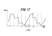
- FIG. 17 is a graph showing an example of an auxiliary function of the preceding stage information acquisition process by the preceding stage information acquisition unit 1413.
- the horizontal axis indicates time, and the vertical axis indicates flow rate.
- This auxiliary function is a function of holding previous-stage information acquired last time until new preceding-stage information is generated, as opposed to the sampling hold function shown in FIG.
- FIG. 17 shows an example in which the minimum value of the flow rate is obtained during the period of communication timings t11 to t12, and the minimum value is transmitted at communication timing t12.
- the extreme value of the flow rate is not detected during the period from the next communication timing t12 to t13, that is, the minimum value is not updated. Therefore, at the communication timing t13, the minimum value (previous value) obtained before the previous communication timing t12 is transmitted. Next, since the maximum value is acquired between communication timings t13 and t14, the maximum value is transmitted at communication timing t14.
- the preceding stage information acquisition section retains the preceding stage information acquired last time when the preceding stage information (extreme value) is not updated.
- the output unit (output unit 1414) at the next communication timing (t13), in addition to the air flow rate, electronically acquires the previous information continuously held by the previous information acquisition unit (previous information acquisition unit 1413). Output to the control device (ECU 100A).
- the ECU 100A can detect the timing at which the pre-stage information of the flow rate data is updated only from changes in the pre-stage information. be.
- FIG. 18 is a graph showing an example of the resonance phenomenon of the intake system of the internal combustion engine 10.
- the intake system of the internal combustion engine 10 has a tubular intake passage 15 as shown in FIG. 1 and has a resonance characteristic.
- This characteristic there is an advantage that the torque of the internal combustion engine 10 can be increased.
- the resonance is used to increase the torque, the pulsation of the intake air increases due to the resonance, and the air flow sensor 12A is in a situation where a pulsation error is likely to occur.
- the vibration source of this resonance is the intake pulsation, which is characterized by being dependent on the speed of the internal combustion engine 10 (engine speed).
- FIG. 18 shows an example of the relationship between the engine speed [rpm] and the amount of intake air.
- the solid line is the graph with resonance
- the dashed line is the graph without resonance.
- the amount of intake air increases and the torque increases.
- FIG. 19 is a graph showing an example of the result of analyzing the resonance phenomenon of the intake system of the internal combustion engine 10.
- FIG. 19 shows the relationship between engine speed [rpm] and pulsation amplitude, intake primary vibration frequency [Hz], and intake primary period (T2) [ms] in order from the top.
- the intake primary vibration frequency is the fundamental frequency of pulsation
- the intake primary period is the reciprocal of the fundamental frequency of pulsation.
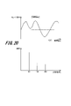
- FIG. 20 is a graph showing an example of an intake pulsation waveform of the internal combustion engine 10 and a frequency analysis result.
- the upper waveform in FIG. 20 is an example of a pulsation waveform when the resonance (engine speed 2400 rpm) in FIG. ) shows the output.
- Frequency analysis of the pulsation waveform in the upper row results in the spectrum in the lower row. Looking at the lower spectrum, it can be seen that the pulsation waveform (fundamental frequency of 80 Hz) includes up to the third harmonic. Also, in order to calculate the pulsation amplitude, it is necessary to store the maximum and minimum values for 12.5 ms and take the difference between them, and it is difficult to calculate the amplitude with the airflow sensor 12A. Recognize. In other words, in order to calculate the pulsation amplitude for 12.5 ms, the airflow sensor 12A needs means for storing the maximum and minimum values for 12.5 ms.
- the accuracy of expressing the waveform of the third harmonic is four times per cycle of the third harmonic. It is considered that the resolution of 4 times per cycle does not provide sufficient information during one cycle and does not provide sufficient accuracy for waveform analysis. Therefore, by performing preliminary information processing on the flow rate data in the airflow sensor 12A during this communication, sufficient accuracy can be obtained for analysis of the pulsation waveform.
- FIG. 21 is a graph showing an example of the intake pulsation waveform of the internal combustion engine 10 and the relationship between control processing.
- This graph shows an analysis example in which the pulsation waveform at an engine speed of 6000 rpm becomes a waveform similar to the pulsation waveform in FIG. 20, based on the same idea as in FIG. T1 represents a communication cycle (for example, 1 ms), and time T2 represents a time corresponding to the first intake cycle (5 ms).
- the pulsation waveform in FIG. 21 has four extreme values (1) to (4) in the first intake cycle at time T2. Also, from the relationship between the communication cycle T1 and the time T2, it can be seen that only five communications can be performed within the time T2 of one combustion cycle. However, by performing the pre-stage information acquisition processing during this communication cycle T1, it becomes possible for the ECU 100A to accurately estimate the pulsation waveform, and it is possible to perform waveform processing at high rotation as well as at low rotation. Recognize.
- the communication cycle T1 between the output section 1414 of the airflow sensor 12A and the input section 1421 of the ECU 100A is sufficiently shorter than the primary intake cycle T2 based on the engine speed. At least, it is desirable that the communication period T1 be a fraction of the pulsation period or less when the engine speed is high.
- FIG. 22 is a graph showing a three-dimensional display example of frequency analysis results of intake pulsations of the internal combustion engine 10.
- FIG. FIG. 22 shows the result of analysis of the relationship between the excitation force due to the intake cycle of the internal combustion engine 10 and the resonance of the intake passage 15 .
- the horizontal axis represents pulsation frequency [Hz]
- the vertical axis represents engine speed [rpm]
- the height of the graph represents pulsation amplitude.
- the pulsation of the intake air resonates with the intake passage 15, maximizing the pulsation amplitude.
- the second harmonic is amplified because the period twice the pulsation period (1/2 frequency) overlaps with the natural frequency of the intake system. Due to such a phenomenon, a complex waveform including harmonics is generated in the output signal of the airflow sensor 12A.
- FIG. 23 is a block diagram showing a configuration example of the pre-stage information processing section 1423 of the ECU 100A.
- the pre-stage information processing section 1423 includes a maximum/minimum value storage section 2311 , a pulsation amplitude calculation section 2312 , an extremum number storage section 2321 and a harmonic detection section 2322 .
- Maximum value/minimum value storage unit 2311 based on the previous information processing period calculated by the previous information processing period calculation unit 1422 and the previous information (extreme value) of the flow data input from the input unit 1421, the period The maximum value and/or minimum value of the flow rate data (pulsation waveform) in the data is obtained and stored in the memory 103M.
- the pulsation amplitude calculation unit 2312 calculates the pulsation amplitude from the maximum and minimum values within the preceding information processing period stored in the maximum/minimum value storage unit 2311 and outputs the pulsation amplitude to the pulsation error calculation unit 1424 .
- the extreme value number storage section 2321 Based on the preceding information processing period calculated by the preceding information processing period calculating section 1422 and the preceding stage information (extreme value) of the flow rate data input from the input section 1421, the extreme value number storage section 2321 The number of extreme values of the flow rate data (pulsation waveform) is obtained and stored in the memory 103M.
- the extreme value number storage unit 2321 stores the number of local minimum values (“( ⁇ ) number of extreme values” in the figure) and the number of local maximum values (“(+) number of extreme values” in the figure) during the preceding information processing period. ) respectively. If the preceding information is not an extreme value but an inflection point, the number of descending inflection points ((-) inflection points) and the number of ascending inflection points ((+) inflection points) are acquired. memorize.
- the harmonic detection unit 2322 detects harmonics based on the number of ( ⁇ ) extrema and the number of (+) extrema in the preceding information processing period stored in the extremum number storage unit 2321 and the harmonics table 2323. Detect features or harmonic orders. Harmonic detector 2322 then outputs the harmonic order to pulsation error calculator 1424 . For example, in the harmonics table 2323, the order of harmonics is defined at the point where the two axes intersect, with the ( ⁇ ) extreme value number and the (+) extreme value number as axes. This harmonic detection is performed in parallel with the pulsation amplitude calculation.
- FIG. 24 is a block diagram showing a configuration example of the pulsation error calculator 1424 of the ECU 100A.
- a pulsation error calculation unit 1424 selects a pulsation correction map from the pulsation correction maps 2400(1) to 2400(n) based on the engine speed, the pulsation amplitude ratio calculated from the pulsation amplitude, and the harmonic order to correct the pulsation. Determine the coefficient.
- the pulsation correction maps 2400(1) to 2400(n) have the same basic configuration as the pulsation correction map 130, and are prepared in advance for each harmonic order and stored in the memory 103M.
- the harmonic order (harmonic waveform) of the flow rate data (pulsation waveform) is detected from the preceding stage information, and the harmonic order is reflected in the pulsation error calculation together with the pulsation amplitude ratio and pulsation frequency.
- a pulsation error coefficient can be calculated.
- the pulsation amplitude ratio may be calculated using the pulsation amplitude ratio calculation means 112 of FIG. 12 instead of the pulsation error calculator 1424. Furthermore, the difference in weather conditions may be reflected in the pulsation correction map.
- the pulsation error may be calculated based on the operating state of the variable valve timing mechanism (the phase of the intake valve 30 and/or the exhaust valve 31) as well as the harmonic order. For example, a pulse rate correction map is created for each combination of harmonic order and valve phase.
- FIG. 25 is a block diagram showing an example of the airflow sensor diagnostic function of the ECU 100A.
- the ECU 100A has a pulsation feature calculation section 2501 and a diagnosis section 2502 .
- the pulsation feature calculation unit calculates pulsation feature information representing the pulsation feature of the corrected air flow rate corrected by the pulsation correction unit (air amount correction unit 1425), and sends the pulsation feature information to the diagnosis unit. (Diagnosis unit 2502).
- the diagnostic unit calculates the air flow rate based on the pulsation feature information of the corrected air flow rate calculated by the pulsation feature information calculation unit (pulsation feature calculation unit 2501) and parameters representing the state of the internal combustion engine 10. Diagnose the measuring device (airflow sensor 12A) and output the diagnosis result.
- the pulsation characteristic information is the pulsation amplitude of the corrected air flow rate
- the parameters representing the state of the internal combustion engine 10 are the rotational speed of the internal combustion engine 10 and the opening of the throttle valve.
- a pulsation amplitude ratio may be used instead of the pulsation amplitude.
- the diagnosis unit 2502 diagnoses that the airflow sensor 12A is abnormal
- the ECU 100A displays the airflow sensor abnormality on the instrument panel or executes fail-safe processing.
- the pulsation error calculator 1424 by correcting the air flow rate (pulsation waveform) measured by the airflow sensor 12A in the pulsation error calculator 1424, the characteristics of the pulsation waveform including harmonics can be reproduced. Therefore, it is possible to highly accurately diagnose the deterioration of the accuracy of the airflow sensor 12A.
- FIG. 26 is a graph showing an example of airflow sensor diagnosis of the ECU 100A.
- FIG. 26 shows an example of diagnosing an abnormality in the airflow sensor 12A based on the highly accurate pulsation amplitude value (or pulsation amplitude ratio) calculated by the air amount correction unit 1425, the engine speed, and the throttle valve opening. ing.
- the pulsation influencing factor such as the variable valve timing mechanism, which can affect the pulsation of the intake air amount is normal. If the airflow sensor 12A is normal, the pulsation is large in the region where the engine speed is low and the throttle valve opening is large, and the pulsation is small in the region where the engine speed is high and the throttle valve opening is small.
- Diagnosis unit 2502 detects that the pulsation of the corrected air flow rate is small despite the region where pulsation is large, or that the pulsation of the corrected air flow rate is large irrespective of the region where pulsation is small. Judged as abnormal. This is useful as a technique using pulsation characteristic parameters (for example, pulsation amplitude or pulsation amplitude ratio) whose accuracy is improved by the present invention.
- pulsation characteristic parameters for example, pulsation amplitude or pulsation amplitude ratio
- the air flow rate measuring device (air flow sensor 12, 12B) according to one embodiment of the present invention provides an output signal (voltage signal) and outputs the air flow rate to the electronic control unit (ECU 100A).
- the air flow rate measuring device (air flow sensor 12, 12B) has a flow rate acquisition section (flow rate acquisition section 1412) that acquires the air flow rate based on the output signal of the sensing section, and based on the air flow rate acquired by the flow rate acquisition section.
- pre-stage information acquisition unit 1413 for acquiring pre-stage information necessary for calculating pulsation correction information (pulsation amplitude, etc.) for the electronic control device to correct the pulsation error of the air flow rate
- An output unit output unit 1414) that outputs the preceding stage information to the electronic control unit (ECU 100A) in addition to the air flow rate.
- the electronic control unit (ECU 100A) is an electronic control unit that controls the internal combustion engine based on the air flow rate taken into the internal combustion engine.
- the electronic control unit (ECU 100A) inputs from the air flow rate measurement device (air flow sensors 12A, 12B) necessary for calculating pulsation correction information (pulsation amplitude, etc.) for correcting the air flow rate pulsation error.
- a pulsation correction information calculation unit (previous information processing unit 1423) that calculates pulsation correction information using the preceding information and the rotational speed of the internal combustion engine obtained from the output signal of the crank angle sensor; 12A, 12B) and a pulsation correction unit (air amount correction unit 1425) that corrects the air flow rate based on the pulsation correction information calculated by the pulsation correction information calculation unit (previous information processing unit 1423); , provided.
- the electronic control unit (ECU 100A) further calculates a processing period (previous information processing period) corresponding to the intake stroke of the internal combustion engine based on the output signal of the crank angle sensor. Harmonics of the pulsation of the intake air are calculated from the calculation unit (processing period calculation unit 1422) and the previous stage information (extreme value or inflection point) input from the air flow rate measuring device (air flow sensor 12A, 12B) during the processing period. and a harmonic detector (harmonic detector 2322) for detection.
- a processing period previously information processing period
- Harmonics of the pulsation of the intake air are calculated from the calculation unit (processing period calculation unit 1422) and the previous stage information (extreme value or inflection point) input from the air flow rate measuring device (air flow sensor 12A, 12B) during the processing period.
- a harmonic detector harmonic detector 2322
- the pulsation correction unit uses the air flow rate input from the air flow rate measurement device (air flow sensors 12A and 12B) and the pulsation correction calculated by the pulsation correction information calculation unit (previous information processing unit 1423).
- the air flow rate is corrected based on the information (pulsation amplitude, etc.) and the harmonic order detected by the harmonic detector (harmonic detector 2322).
- the air flow rate measuring device uses pulsation correction information (for example, pulsation amplitude) for correcting the pulsation error of the air flow rate (pulsation waveform). Instead, it acquires the extreme value or inflection point, which is the information in the previous stage, and outputs it to the electronic control unit (ECU 100A). Therefore, it is possible to reduce the calculation load of the air flow rate measuring device (air flow sensors 12, 12B). Therefore, in the present embodiment, the intake air amount is accurately calculated by correcting the error due to the pulsation of the output signal of the air flow measurement device without increasing the calculation load of the air flow measurement device (air flow sensors 12A and 12B). can do.
- pulsation correction information for example, pulsation amplitude
- the electronic control unit can control the control target such as the internal combustion engine based on the highly accurate intake air amount.
- the control target such as the internal combustion engine
- the electronic control eliminates this problem.
- the electronic control device ECU 100A It is possible to improve the accuracy of information (maximum value, minimum value) necessary for calculating pulsation correction information (pulsation amplitude, etc.) on the side.
- the preceding stage information (extreme value or inflection point) of the flow data is compared with the calculation period of the electronic control unit (ECU 100A) and high frequency sampling (for example, period 1 ms ), the accuracy of the preceding stage information to be acquired is high.
- the electronic control unit (ECU 100A) that can grasp the engine speed and crank angle is not on the side of the air flow measuring device (air flow sensor 12A, 12B) that is difficult to grasp the engine speed and crank angle.
- pulsation correction information (pulsation amplitude, etc.) is calculated on the side. Therefore, it is possible to calculate the pulsation in consideration of the engine speed and crank angle. Therefore, it is possible to distinguish whether the output signal of the air flow measuring device (air flow sensor 12, 12B) is a transient response or a pulsation, or whether it is a pulsation or a harmonic, and the accuracy of the pulsation correction of the air flow measurement system as a whole is improved. do.
- any one of the temperature, humidity, and pressure measured by other sensors may be transmitted to the ECU 100A through the SLOW channel of SENT communication.
- the present invention is not limited to the above-described embodiment, and of course, various other applications and modifications can be made without departing from the gist of the present invention described in the claims.
- the configuration of the air flow rate measuring device (airflow sensors 12A, 12B) and the electronic control unit (ECU 100A) is described in detail and concretely in order to explain the present invention in an easy-to-understand manner. It is not limited to having all the components described. Moreover, it is also possible to add, replace, or delete other components for a part of the configuration of each embodiment.
- each of the above configurations, functions, processing units, etc. may be realized by hardware, for example, by designing a part or all of them with an integrated circuit.
- a broadly defined processor device such as FPGA (Field Programmable Gate Array) or ASIC (Application Specific Integrated Circuit) may be used.
- control lines and information lines indicate those that are considered necessary for explanation, and not all the control lines and information lines are necessarily indicated on the product. In practice, it may be considered that almost all components are interconnected.
Landscapes
- Physics & Mathematics (AREA)
- Fluid Mechanics (AREA)
- General Physics & Mathematics (AREA)
- Measuring Volume Flow (AREA)
Abstract
エアフローセンサでは情報が不足していて算出することが難しい脈動振幅などの計算は行わず、脈動波形の極値などの前段情報をエアフローセンサ内で計算し、エアフローセンサから空気流量と前段情報を電子制御装置に送信する。電子制御装置では受信した前段情報に対し、脈動誤差の補正に必要な脈動補正情報(脈動振幅等)を加えて脈動補正を行う。
Description
本発明は、空気流量計測装置、電子制御装置、及び空気流量計測システムに関する。
近年、自動車等の車両の燃費や排気の規制が強化されつつあり、そのような規制は今後も益々強くなる傾向にある。吸入空気量は燃料噴射量演算に使用されるパラメータであり、今後より一層厳しくなる規制に対応するためには、高精度な吸入空気量検出が必須である。エアフローセンサの出力結果は燃費及び排気性能を左右するため、エアフローセンサの吸入空気量検出精度を上げるための技術開発が盛んに行われている。
吸入空気量を計測できるエアフローセンサとして現在多く使用されているものは熱線式エアフローセンサであり、このエアフローセンサの検出信号としては発熱抵抗体からの信号に基づいて空気量に応じて電圧値を変える電圧信号や、空気量に応じて出力パルスの周期を変える周波数信号を使うものもある。さらには、エアフローセンサの出力信号精度を向上する手法としてデジタル通信機能も使うものもある。
吸入空気量については、内燃機関においてピストンの往復運動により吸気管に吸気脈動が発生するため、定常状態においても熱線式エアフローセンサの検出信号も機関回転数[rpm]と吸気脈動に同期した変動が発生する。
特に、スロットルバルブの上流に配置される熱線式エアフローセンサは、スロットルバルブ開度が脈動に対して通気抵抗が低下する開度より開き側では、吸気脈動の影響を受けやすくなり、検出信号を平滑化しても真の空気量に対して誤差を生じることが知られている。この吸気脈動により生じる誤差のことを脈動誤差という。このため、特許文献1において、吸気脈動に対して空気量の補正を行う方法が提案されている。
また、エアフローセンサと制御装置の間を通信により情報伝達する場合の通信負荷増大の課題に対し、特許文献2に記載されたような方法が開示されている。特許文献2では、空気流量出力に基づいて、空気流量を取得する流量取得部と、流量取得部で取得した空気流量に基づいて、空気の脈動による空気流量の誤差である脈動誤差を補正するための脈動補正情報を取得する補正情報取得部と、空気流量に加えて、脈動補正情報を電子装置に出力する出力部を備える方法が開示されている。
特許文献1に記載の吸入空気量を補正する方法は、吸気の脈動振幅比を算出する場合に、吸気管圧力、スロットルバルブの操作量、あるいは機関回転数に基づいて補正量を演算する方法である。
また、特許文献2に記載の方法は、エアフローセンサと制御装置の間を通信する際の通信負荷を低減するために、エアフローセンサ内で、脈動補正情報を取得し通信を介して制御装置に送信する方法である。この手法では、エアフローセンサで脈動補正情報を取得するので、メリットとしては高速サンプルで処理可能であるが、脈動算出が高速演算で行うのでエアフローセンサ内の処理負荷が高くなる課題がある。また、エアフローセンサはエンジンの角度情報がないために、脈動算出に用いる情報をどの期間保持すればよいか不明確であり、脈動波形が高調波を含む脈動の場合の振幅計算が困難な課題がある。特にエンジンが低回転域では、脈動算出に用いる情報の保持期間が長くなることが懸念される。
上記課題を踏まえ、一定の運転領域(回転数と負荷の関係)に限定して効果を得ることは可能である。しかし、実際の車両の動作状態において、一定の運転領域以外を使うことがあるので、その際には、燃料噴射量や、その他エンジン動作パラメータに誤差が生じる可能性がある。
例えば、エンジンの動作条件が安定しやすいハイブリッド車においても、連続登坂などにより、バッテリーエネルギーが消耗してエンジンで発生させるエネルギーを増加させる必要がある。このような状況の際には、エンジン負荷の増大により動作条件が変わり、脈動波形が変化する。例えば、エンジン回転数の増加により脈動周期が短くなり、想定した脈動計測ができないことが考えられる。
したがって、特許文献2では、エアフローセンサ内で脈動を算出するが、脈動を算出するためには、内燃機関10の回転に同期したウィンドウ(算出期間)内で算出する必要があるため、エアフローセンサ内で回転に同期させるためには、脈動波形を使う必要がある。しかしながら、脈動波形はエンジンの動作条件によって異なる。このため、高い精度で脈動を算出するためには、高度な推定技術が必要となる。また、動作条件の過渡時には、過渡による変動と脈動を切り分ける必要がある。
ここで、熱線式エアフローセンサは、測定対象である吸入空気流の中に配置された発熱抵抗体に流れる電流値は吸入空気量が多いときに増加し、逆に吸入空気量が少ないときに減少するようにブリッジ回路が構成されている。そして、発熱抵抗体に流れる電流により空気量信号が取り出される。
熱線式エアフローセンサは発熱抵抗体の熱収支を利用しているため、吸気脈動の影響を受けた場合に脈動の大きさや周波数によって検出精度へ影響を及ぼし、特に熱線式エアフローセンサの出力としては高周波数領域ほど応答遅れが生じる周波数応答特性を持っている。よって、出力特性が非線形特性を持つ場合には検出される出力平均値と真の空気量平均値が一致しなくなり誤差が生じるようになる。また、この誤差は大脈動、高周波数ほど大きくなる傾向にある。
本発明は、上記の状況に鑑みてなされたものであって、エアフローセンサの演算負荷を増加させずに、エアフローセンサの出力信号の脈動による誤差を補正して吸入空気量を精度良く演算することを目的とする。
上記課題を解決するために、本発明の一態様の空気流量計測装置は、空気が流れる環境に配置されるセンシング部の出力信号に基づいて空気流量を測定し、空気流量を電子制御装置に出力するものである。この空気流量計測装置は、上記出力信号に基づいて、上記空気流量を取得する流量取得部と、当該流量取得部で取得した空気流量に基づいて、空気流量の脈動誤差を上記電子制御装置が補正するための脈動補正情報を算出するために必要な前段情報を取得する前段情報取得部と、空気流量に加えて、前段情報を電子制御装置に出力する出力部と、を備える。
また、本発明の一態様の電子制御装置は、内燃機関に吸入される空気流量に基づいて当該内燃機関を制御するものである。この電子制御装置は、上記空気流量の脈動誤差を補正するための脈動補正情報を算出するために必要な、空気流量計測装置から入力された前段情報と、クランク角センサの出力信号から得られる内燃機関の回転数とを用いて脈動補正情報を算出する脈動補正情報算出部と、空気流量計測装置から入力された空気流量、及び、脈動補正情報算出部で算出された脈動補正情報により空気流量を補正する脈動補正部と、を備える。
また、本発明の一態様の空気流量計測システムは、上記空気流量計測装置と上記電子制御装置とを備える。
本発明の少なくとも一態様によれば、空気流量計測装置の演算負荷を増加させずに、空気流量計測装置の出力信号の脈動による誤差を補正して吸入空気量を精度良く演算することができる。それゆえ、良い精度の吸入空気量に基づいて内燃機関等の制御対象を制御できる。
上記した以外の課題、構成及び効果は、以下の実施形態の説明により明らかにされる。
上記した以外の課題、構成及び効果は、以下の実施形態の説明により明らかにされる。
以下、本発明を実施するための形態の例について、添付図面を参照して説明する。本明細書及び添付図面において実質的に同一の機能又は構成を有する構成要素については、同一の符号を付して重複する説明を省略する。
<一実施形態>
図1は、本発明の一実施形態に係る流量計測システムが適用される内燃機関の全体構成の一例を示した概略構成図である。
図1は、本発明の一実施形態に係る流量計測システムが適用される内燃機関の全体構成の一例を示した概略構成図である。
図1で示す内燃機関10は、例えば4つの気筒を備えた火花点火式の多気筒エンジンである。内燃機関10は、シリンダヘッド29a及びシリンダブロック29bからなるシリンダ29と、このシリンダ29の各気筒内に摺動自在に嵌挿されたピストン27と、を備える。ピストン27は、コンロッド28を介してクランク軸(図示せず)に連結されている。また、ピストン27の上方には、所定形状の天井部を有する燃焼室26が画成されている。各気筒の燃焼室26には、点火コイル20から高電圧化された点火信号が供給される点火プラグ19が臨設されている。
また、燃焼室26は、エアクリーナ11、スロットルバルブ13、コレクタ16、吸気マニホールド17、吸気ポート18等を備えた吸気通路15と連通している。燃料の燃焼に必要な空気は、この吸気通路15を通り、当該吸気通路15の下流端である吸気ポート18の端部に配在された吸気カム軸22により開閉駆動される吸気バルブ30を介して、各気筒の燃焼室26に吸入されるように構成されている。また、吸気通路15の吸気マニホールド17には、吸気ポート18へ向けて燃料を噴射するインジェクタ21が気筒ごとに臨設されている。
また、吸気通路15のエアクリーナ11の下流には、吸入空気量を検出するエアフローセンサ12が配設されている。吸気通路15を介して吸入された空気とインジェクタ21から噴射された燃料との混合気は、吸気バルブ30を介して燃焼室26へ吸入され、点火コイル20に接続された点火プラグ19による火花点火によって燃焼される。そして、燃焼室26での燃焼後の排気ガスは、排気カム軸23により開閉駆動される排気バルブ31を介して燃焼室26から排気され、排気ポートや排気マニホールド、排気管等(不図示)を備えた排気通路32を通って外部の大気中へ排出されるように構成されている。
さらに、排気通路32の下流側には、アルミナやセリアなどの担体に白金やパラジウムなどを塗布した排気ガス浄化用の三元触媒35が配設されている。三元触媒35の上流側には、触媒前空燃比に対して線形の出力特性を有する空燃比センサ33が配設されている。三元触媒35の下流側には、触媒後空燃比がストイキ(理論空燃比)よりもリッチ側かリーン側かを識別するためのスイッチング信号を出力するO2センサ34が配設されている。
また、内燃機関10の各気筒に対して配備されたインジェクタ21は、燃料タンク36と接続されている。燃料タンク36の内部の燃料は、燃料ポンプ37や燃圧レギュレータ38等を備えた燃料供給機構により所定燃圧に調圧されてインジェクタ21に供給されるように構成されている。所定燃圧の燃料が供給されたインジェクタ21は、ECU(Engine Control Unit)100から供給されるエンジン負荷等の運転状態に応じたデューティ(パルス幅:開弁時間に相当する)を有する燃料噴射パルス信号によって開弁駆動される。そして、インジェクタ21は、その開弁時間に応じた量の燃料を吸気ポート18に向けて噴射するように構成されている。
なお、ECU100は、内燃機関10の種々の制御、例えばインジェクタ21による燃料噴射制御(空燃比制御)、点火プラグ19による点火時期制御等を行うためのマイクロコンピュータを内蔵している。
図2は、ECU100の全体構成を示したものである。ECU100は、電子制御装置の一例であり、電源IC101とLSI102とから構成されている。LSI102のRESET端子(図示略)は、電源IC101で制御されるRESET信号が送信可能なように、電源IC101に接続されている。
また、ECU100には、内燃機関10の制御に必要なセンサ類、例えば機関回転数を検出するためのクランク角センサ25、内燃機関10の冷却水温度を検出するための水温センサ40、スロットルバルブ開度を検出するスロットルセンサ14、排気ガス中の酸素濃度を検出するための空燃比センサ33、スタータスイッチ41、エアフローセンサ12等の信号が入力される。
これらのセンサからの検出信号はECU100内のLSI(入力処理回路)102に入力され、アナログ入力としてA/D変換器により検出されるものと、High/Lowレベルで検出されるものとに分かれて処理される。
CPU103では、LSI102内のメモリ103Mに格納されているプログラムによって、所定のデジタル演算処理を実行する。そして、CPU103は、その演算結果から内燃機関10の制御に必要な各種アクチュエータの制御信号を出力し、LSI102の出力回路を介して各種アクチュエータを制御する機能を有している。メモリ103Mは、不揮発性又は揮発性の半導体メモリから構成され、パラメータや演算処理の途中に発生した変数、後述する脈動補正マップや高調波テーブルなどを記憶する。
例えば、CPU103は、各インジェクタ21について、熱線式のエアフローセンサ12の検出信号から計測される質量流量と、クランク角センサ25から計測される内燃機関10の回転数、及び水温センサ40から検出される水温を含む各補正量、空燃比センサ33によって検出される空燃比状態に応じた補正量を付加して、燃料噴射量を演算する。そして、CPU103は、インジェクタ21ごとに演算した燃料噴射量に基づいて、内燃機関10の各インジェクタ21に駆動パルス幅として制御信号を出力する。同様に、CPU103は、内燃機関10の燃焼に必要な点火コイル20への通電タイミングを制御する点火信号、スロットルバルブ開度を制御する図示しない電制スロットルへの制御信号などを出力する。
次に、熱線式エアフローセンサ12の概要について説明する。熱線式エアフローセンサ12は、測定対象である空気流の中に配置された発熱抵抗体を主要な構成要素とする。熱線式エアフローセンサ12には、発熱抵抗体に流れる電流値は吸入空気量が多いときに増加し、逆に吸入空気量が少ないときには減少するようにブリッジ回路が構成されており、熱線式エアフローセンサ12は、発熱抵抗体に流れる電流により空気量を電圧信号として取り出す。なお、空気量に対応した電圧信号は電圧値として出力されるほか、電圧-周波数変換回路によって変換することにより周波数信号に変換されて出力されるものもある。
図14以降に示す本発明に係る空気流量計測システムでは、デジタル通信を利用して、エアフローセンサ12から流量データをECU100に送信している。ここでは、空気流量計測の基本的な仕組みを説明するために、エアフローセンサ12から計測結果を電圧(アナログ信号)で出力する場合について説明する。
図3は、一般的な熱線式エアフローセンサ12の出力信号に基づいて空気量を求める演算方法を示しており、この演算はECU100の内部処理で実行されるものである。例えば、A/D変換器104の分解能を10ビット、CPU103が認識する1ビット当たりの電圧を5mV相当とした場合、1.0VをA/D変換するとデジタル値は200となる。
A/D変換器104から出力された電圧情報Vaは、空気量変換テーブル105に与えられる。空気量変換テーブル105は、電圧情報Vaに対応して予め記憶された空気量を有している。電圧情報Vaは、空気量変換テーブル105により検索補間演算されて、検出空気量に変換される。以下、検出空気量は、この空気量変換テーブル105で変換された空気量を示すものとして説明する。
また、図示しないが電圧-周波数変換された周波数信号がエアフローセンサ12からECU100に入力される場合は、信号の周期をCPU103のポート入力で計測することによって、周期、又は周期から周波数に変換された値が空気量変換テーブル105の入力となる。周期、又は周期から周波数に変換された値は、空気量変換テーブル105において、周期又は周波数に応じて予め記憶された値から検索補間演算されて検出空気量に変換される。空気量変換テーブル105で得られた空気量信号Qは、その後に高周波成分ノイズの除去を目的としたデジタルフィルタ処理106を実行されて検出空気量Qcを演算する。
燃料噴射パルス幅演算手段107では、検出空気量Qcを別途クランク角センサ25の信号から演算した内燃機関10の回転数(以下「機関回転数」)115で除算し、シリンダ29に吸入される空気量相当に変換する。また、上述した各補正演算が行われた後、燃料噴射パルス幅演算手段107は、燃料を噴射する時間Toutを演算し、インジェクタ21にて燃料を内燃機関10に供給するように動作する。
図4は、一般的な熱線式エアフローセンサ12の吸入空気量と出力信号の関係を示したものである。図4では、吸入空気量が少ないと出力する信号の電圧は低く、吸入空気量が多いと出力する信号の電圧は高くなる非線形関係にある特性曲線の例が示されている。非線形性特性とするのは、発熱抵抗体からの検出信号を空気量に変換する際に空気量Qは、主としてキングの式と呼ばれる次の式が採用されているためである。
Ih・Rh=(α+β・√Q)・(Th-Ta)
Ih・Rh=(α+β・√Q)・(Th-Ta)
ここで、Ihは発熱抵抗体の電流値、Rhは発熱抵抗の抵抗値、Thは発熱抵抗の表面温度、Taは空気の温度、Qは空気量、α、βは発熱抵抗の仕様で決まる定数である。
一般的には、(Th-Ta)が一定となるように発熱抵抗の電流値Ihを制御するので、空気量は抵抗器の電圧降下により電圧値Vに変換して検出するが、結果として電圧値Vは4次関数式になる。このため、空気量へ変換する場合に、4次曲線の曲率すなわち出力と空気量との関係が非線形になる。
なお、特性曲線については、内燃機関10の要求空気量に合わせて熱線式エアフローセンサ12の出力を設定する。そのため、周波数と空気量あるいは電圧と空気量との関係が逆の特性の場合や、或いは線形関係のケースもあるが、演算処理については空気量変換テーブル105が変わるだけである。
図5、図6及び図7を用いて、熱線式エアフローセンサ12の周波数特性を説明する。熱線式エアフローセンサ12は発熱抵抗体の熱収支を利用しているため、実際の空気量の変化(脈動波形)に対して遅れが生じる。この遅れのことを応答遅れという。図5は脈動周波数が低いときの実際の空気量の変化と熱線式エアフローセンサ12の出力値を示している。脈動周波数が低いときは、熱線式エアフローセンサ12の出力は、実際の空気量の変化にほとんど遅れることなく追従できる。
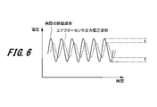
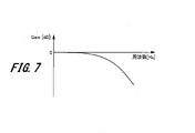
一方、図6のように脈動周波数が高くなると、熱線式エアフローセンサ12の出力は、実際の空気量の変化(脈動波形)を追従できなくなり、減衰してしまう。この現象は脈動周波数が高くなるほど顕著となり、その様子を示したものが図7である。図7は、熱線式エアフローセンサ12の周波数特性を示したもので、横軸が周波数[Hz]、縦軸がゲイン[dB]である。ゲイン=0dBのときは減衰なし、ゲインがマイナスになるほど入力信号波形に対して出力信号波形が減衰していくことを示している。
以上より、熱線式エアフローセンサ12は、脈動周波数が高周波数であるほど出力電圧波形が減衰することが分かる。ここで、出力電圧波形が減衰した際の空気量への影響について図8を用いて説明する。図8は、電圧と空気量の関係を示している。実際の空気量の脈動振幅を(A)、そのときの空気量を電圧に変換したときの電圧の振幅を(B)としたとき、熱線式エアフローセンサ12の周波数特性により電圧の振幅(B)が減衰すると振幅(C)となり、その電圧を空気量に変換したときの空気量の振幅は(D)となる。
実際の空気量の脈動は振幅(A)であるため、そのときの平均空気量はQAであるが、熱線式エアフローセンサ12の周波数応答遅れにより減衰した出力電圧波形を空気量に変換すると平均空気量はQDとなる。すなわち、熱線式エアフローセンサ12により計測される空気量は、実際の空気量に対して(QA-QD)だけマイナス誤差となる。熱線式エアフローセンサ12の周波数特性上、周波数が高くなるほど出力電圧波形の減衰が大きくなるため、マイナス誤差は大きくなる。
また、熱線式エアフローセンサ12は高周波数のときだけではなく、脈動が大きいときほどマイナス誤差が大きくなる性質を持っている。図9と図10は、脈動周波数は同じで、図9は脈動が小さい場合、図10は脈動が大きい場合の実際の空気量と熱線式エアフローセンサ12の出力値を示したものである。
図9に示すように脈動が小さい場合、熱線式エアフローセンサ12は実際の空気量変化に追従できている。しかし、図10に示すように脈動が大きい場合、熱線式エアフローセンサ12は実際の空気量変化に追従できないため、出力電圧波形が減衰してしまう。その結果、先ほど図8で説明したように、出力電圧波形が減衰することでマイナス誤差が発生してしまう。
ところで、熱線式エアフローセンサ12は脈動の大きさと脈動周波数により、脈動誤差をある程度予測することができる。ここで、脈動の大きさを示す指標として、脈動振幅比(脈動率)を用いる。脈動振幅比とは、下記の式(1)に示すように、脈動時の最大流量と最小流量の差分である脈動振幅量を、そのときの平均空気量で除したものであり、平均空気量に対してどの程度振動しているのかを示す指標である。
脈動振幅比=(脈動最大流量-脈動最小流量)/平均空気量×100[%] ・・・(1)
脈動振幅比=(脈動最大流量-脈動最小流量)/平均空気量×100[%] ・・・(1)
図11は、脈動誤差の傾向を周波数違いで示したものである。逆流検知が可能なエアフローセンサの場合、図11に示すように脈動誤差カーブはS字を描く特性を持っている。前述したように、脈動誤差は周波数が高くなるほど全体的にマイナス誤差となる。ただし、脈動誤差自体は脈動振幅比と脈動周波数が分かればほぼ予測できるため、熱線式エアフローセンサ12の出力値を空気量変換テーブル105で空気量に変換した結果に対して、補正を加えることで脈動誤差の影響を取り除くことができる。
図12を用いて、脈動誤差を算出して吸入空気量を補正する従来の方法について説明する。図12は、熱線式エアフローセンサ12の出力信号を用いた空気量演算方法をECU100で実行する場合の内部処理の概要を示したものである。図12において、熱線式エアフローセンサ12の出力は、A/D変換器104、サンプリング手段108、空気量変換テーブル105を介して吸入空気量が演算され、これらにより吸入空気量演算手段50が構成される。
ECU100で実行する内部処理は、図面上では制御機能或いは演算機能をブロックとして表現している。この内部処理ブロックは、A/D変換器104からの出力Vaを入力として、第一の所定期間であるサンプリングタイミング(例えば2ms)でサンプリング手段108を用いてA/D変換値を参照する。このA/D変換値は、図7で説明したように周波数特性により減衰した値であるため、周波数応答遅れ補正手段109を用いて減衰前の値に戻す必要がある。そのため、機関回転数115から脈動周波数演算手段110を用いて現在の脈動周波数を演算し、脈動周波数から出力電圧波形の減衰量を予測し、周波数応答遅れ補正手段109にて出力電圧波形を減衰前の値に復元する。
その後、空気量変換テーブル205を用いて空気量に変換する。空気量変換テーブル205と空気量変換テーブル105は同じものではある。ただし、空気量変換テーブル105は、サンプリング手段108でA/D変換した電圧値を直接空気量に変換するが、空気量変換テーブル205は、周波数応答遅れ補正手段109により周波数応答遅れを補正した後の電圧値を空気量に変換する、という違いがあるため、区別した記述としている。空気量変換テーブル205で変換された空気量は、サンプリング記憶手段111により第二期間(第一期間よりも長く、例えば20ms)の空気量が記憶、保存される。そして、脈動振幅比演算手段112により、第二期間の最大空気量、最小空気量、平均空気量から脈動振幅比を演算する。
脈動周波数演算手段110より求まる脈動周波数と、脈動振幅比演算手段112より求まる脈動振幅比とから、脈動誤差が推測できるため、脈動誤差が小さくなるように脈動誤差算出手段113により脈動誤差を算出して補正する。脈動誤差算出手段113には、脈動誤差を算出して空気量補正手段114で補正するための脈動補正マップがある。
図13に脈動補正マップ130を示す。脈動補正マップ130は、脈動振幅比[%]と脈動周波数[Hz]を軸としている。図13では脈動振幅比を100%刻み、脈動周波数を20Hz刻みで記述した例を示しているが、もちろんこの間隔は任意に設定することができる。例えば、脈動振幅比を50%刻みやそれより細かく設定してもよく、脈動周波数も10Hz刻みやそれより細かく設定してもよい。実際に検出される脈動振幅比、脈動周波数はこれらの間になることが多く、その場合は補間計算により求めることとなる。脈動誤差算出手段113は、脈動振幅比と脈動周波数とに基づいて、脈動誤差を補正するために必要な脈動補正係数を脈動補正マップ130から参照する。
図13に示す脈動補正マップ130は、例えば脈動振幅比が300%のとき、脈動周波数20Hzで「1」、40Hzで「1.02」、60Hzで「1.05」、80Hzで「1.07」、100Hzで「1.09」、120Hzで「1.12」と徐々に大きくなる。また、脈動周波数が60Hzのとき、脈動振幅比0%で「1」、100%で「0.99」、200%で「0.98」、300%で「1.05」、400%で「1.1」、500%で「1.07」、600%で「1.05」、700%で「1.02」、800%で「0.97」、900%で「0.95」となり、400%でピークとなるように設定されている。なお、図示していないが、空欄の個所にも上記と同じ傾向で、すなわち、脈動周波数が60Hzの補正係数を参照して、脈動周波数が20~120Hzに上昇すると脈動補正係数が大きくなるように設定されている。
脈動振幅比ごとの脈動補正係数の設定は、熱線式エアフローセンサ12の脈動特性により、脈動誤差が小さくなるように設定するとよい。脈動振幅比の定義上、脈度振幅比が200%以上になると逆流が発生することとなるが、熱線式エアフローセンサ12は前述したように、低脈動時には脈動誤差が小さいので、逆流が発生しない脈動振幅比200%以下では誤差が小さい。そのため、脈動補正マップ130においても、脈動振幅比が200%以下では脈動補正係数が小さい値に設定される。なお、この脈動補正マップ130では、脈動振幅比が800%、900%のときにも、脈動補正係数は小さく設定されているが、この領域では実験に基づいて脈動補正係数が設定されている。
脈動誤差算出手段113の脈動補正マップ130から脈動補正係数を参照した後、空気量補正手段114にて脈動誤差を補正した空気量を演算する。空気量補正手段114では、サンプリング手段108によりA/D変換した電圧値を空気量変換テーブル105で直接変換した空気量に対して、脈動誤差算出手段113で参照した脈動補正係数を掛けることで脈動誤差を補正した空気量を演算することができる。
以上、脈動補正の基本的な仕組みを説明するために、エアフローセンサ12が吸入空気の流量に応じた信号を電圧で出力する場合について説明した。以下では、デジタル通信を利用して、エアフローセンサから吸入空気の流量に応じた流量データ(デジタル信号)をECU100に送信する実施形態の例について説明する。
[空気流量計測システム]
図14は、本発明の一実施形態に係る空気流量計測システムの構成例を示すブロック図である。図14において、空気流量計測システムは、エアフローセンサ12A(空気流量計測装置)とECU100A(電子制御装置)を備え、エアフローセンサ12Aが検出した吸入空気の流量(吸入空気量)に基づいて、ECU100Aが吸入空気の流量を補正する。
図14は、本発明の一実施形態に係る空気流量計測システムの構成例を示すブロック図である。図14において、空気流量計測システムは、エアフローセンサ12A(空気流量計測装置)とECU100A(電子制御装置)を備え、エアフローセンサ12Aが検出した吸入空気の流量(吸入空気量)に基づいて、ECU100Aが吸入空気の流量を補正する。
エアフローセンサ12Aは、上述したエアフローセンサ12に対して、吸入空気の流量に応じた流量データ(デジタル信号)を出力するように改良した空気流量計測装置である。センシング部1411と、流量取得部1412と、前段情報取得部1413と、出力部1414を備える。エアフローセンサ12Aは、図示しないプロセッサとメモリを備えている。プロセッサはエアフローセンサ12Aの各ブロックを統括的に制御する。例えば、プロセッサとメモリが協働して前段情報取得部1413の機能が実現される。
センシング部1411は、上述した発熱抵抗体を主要な構成要素とするブリッジ回路で構成され、吸入空気の流量(吸入空気量)に応じて発熱抵抗体に流れる電流を電圧信号(アナログ信号)として取り出して、電圧信号を流量取得部1412へ出力する。
流量取得部1412は、A/D変換器104と同様の機能を持つ。すなわち、流量取得部1412は、センシング部1411から入力されたアナログ信号の電圧信号をアナログ-デジタル変換し、デジタル信号(流量データ)を前段情報取得部1413へ出力する。
前段情報取得部1413は、流量取得部1412から入力される流量データ(脈動波形)からその特徴を表す情報を取得し、当該流量データの特徴を表す情報を前段情報として出力部1414へ出力する。前段情報は、吸入空気量の脈動誤差をECU100Aが補正するための脈動補正情報を算出するために必要な情報であり、例えば脈動波形の極値や変曲点についての情報である。この前段情報取得部1413の詳細については、後述の図16及び図17を参照して説明する。
出力部1414は、A/D変換器104から入力される流量データと、前段情報取得部1413から入力される前段情報とを含んだ通信信号を生成して、その通信信号をECU100Aの入力部1421へ送信する。例えば、エアフローセンサ12Aの出力部1414とECU100Aの入力部1421とはそれぞれ、SENT(Single Edge Nibble Transmission)通信のプロトコルに準拠して接続されている。すなわち、出力部1414は、SENT通信のプロトコルに従って通信信号を生成し、その通信信号をECU100Aへ出力するように構成されている。
このように、本実施形態では、前段情報取得部(前段情報取得部1413)は、前段情報として空気流量(流動データ)の極値の情報を算出する極値算出機能を有し、出力部(出力部1414)は、空気流量に加えて、その極値の情報を電子制御装置(ECU100A)に出力するように構成されている。
また、本実施形態の他の例として、前段情報取得部(前段情報取得部1413)は、前段情報として空気流量(流動データ)の変曲点の情報を算出する変曲点算出機能を有し、出力部(出力部1414)は、空気流量に加えて、その変曲点の情報を電子制御装置(ECU100A)に出力するように構成してもよい。
SENT通信は、シリアル通信規格の一つであって、単方向/単線式通信プロトコル(SAE J2716)である。SENT通信では、データ値は信号の立ち下がりエッジから次の立ち下がりエッジまでの時間としてエンコードされる。SENT通信は、2種類のデータ値を送ることが可能である。例えば、出力部1414は、流量データと前段情報をFASTチャネルで送信する。
ECU100Aは、入力部1421と、前段情報処理期間算出部1422と、前段情報処理部1423と、脈動誤差算出部1424と、空気量補正部1425を備える。ECU100内のCPU103は、ECU100Aの各ブロックを統括的に制御する。
入力部1421は、エアフローセンサ12Aから入力された、流量データと前段情報を含む通信信号に対して入力処理を行う。そして、入力部1421は、通信信号に含まれた流量データを空気量補正部1425に出力するとともに、通信信号に含まれる前段情報を前段情報処理部1423へ出力する。例えば、入力部1421は、SENT通信のプロトコルに従ってエアフローセンサ12Aから通信信号を受信するように構成されている。なお、入力部1421は、通信信号に含まれた流量データ及び前段情報を一旦メモリ103Mに記憶してもよい。
前段情報処理期間算出部1422は、クランク角センサ25の出力信号(回転数情報)から時間当たりの所定の回転角度(deg)に相当する時間を算出し、この時間を前段情報処理期間として前段情報処理部1423へ出力する。前段情報処理期間は、少なくとも1以上の吸気行程に相当する期間であればよいが、2以上の吸気行程に相当する期間であることが望ましい。このような何らかの目的で設定された期間は、一般に「ウィンドウ」とも呼ばれる。また、抜け漏れなく、前段情報を処理するためには、最低でも1燃焼サイクルに1回は処理することが望ましい。例えば、4気筒であれば180deg、3気筒であれば240degに1回は処理が必要である。
前段情報処理期間は、内燃機関10の回転速度とシリンダ数により決定するが、所定のクランク角度ごとに決定してもよい。例えば、回転速度とシリンダ数により決定する例として3気筒の場合には、240degごとに、480degの範囲に相当する期間を前段情報処理期間として前段情報処理を行う。なお、吸気行程のタイミングは、クランク角センサ25の出力信号に含まれる基準信号、例えばクランクプレートの信号歯の歯欠けに相当する信号から検出可能である。
前段情報処理部1423は、入力部1421から入力された流量データの前段情報に基づいて、前段情報処理期間算出部1422から入力される前段情報処理期間の脈動補正情報を算出する。既述したように脈動補正情報は、吸入空気量(空気流量)の脈動誤差を補正するために用いられる情報である。よって、前段情報処理部1423は、脈動補正情報算出部であるとも言えるし、前段情報から流量データ(脈動波形)を分析することから波形分析部とも言える。前段情報処理部1423は、吸気行程ごとなどの所定のタイミングで脈動補正情報を算出して脈動誤差算出部1424へ出力する。この前段情報処理部1423の詳細については、後述の図23を参照して説明する。
脈動誤差算出部1424は、クランク角センサ25のクランク角信号から得られる回転数を考慮し、吸入空気量の脈動誤差すなわち脈動補正係数を算出して空気量補正部1425へ出力する。この脈動誤差算出部1424の詳細については、後述の図24を参照して説明する。
空気量補正部1425は、脈動誤差算出部1424から入力される脈動補正係数を用いて、入力部1421を介してエアフローセンサ12Aから受信した流量データを補正し、脈動誤差が補正(低減)された空気量情報を得ることができる。なお、本実施形態では、流量データ(流量値)に脈動補正係数を乗算して流量データを補正するが、これに限定されない。例えば、脈動補正係数ではなくて補正量を登録した脈動補正マップを用意し、流量データ(流量値)に補正量を加算してもよい。あるいは、流量データ(流量値)に補正係数を乗算してから補正量を加算するようにしてもよい。
[エアフローセンサの変形例]
ここで、エアフローセンサ12Aの変形例について図15を参照して説明する。
図15は、エアフローセンサ12Aの変形例を示すブロック図である。図15に示すエアフローセンサ12Bは、図14に示したエアフローセンサ12Aと比較して、流量取得部1412と前段情報取得部1413との間に周波数応答遅れ補正部1415を備える点が異なる。
ここで、エアフローセンサ12Aの変形例について図15を参照して説明する。
図15は、エアフローセンサ12Aの変形例を示すブロック図である。図15に示すエアフローセンサ12Bは、図14に示したエアフローセンサ12Aと比較して、流量取得部1412と前段情報取得部1413との間に周波数応答遅れ補正部1415を備える点が異なる。
周波数応答遅れ補正部1415は、図12に示した周波数応答遅れ補正手段109と同様に、A/D変換後の信号波形に対して周波数応答遅れ補正を行う。すなわち、周波数応答遅れ補正部1415は、現在の吸入空気量の脈動周波数を基に、流量取得部1412から出力される流量データの信号波形の周波数応答遅れによる減衰量を予測し、当該信号波形の値を減衰前の値に復元する。そして、周波数応答遅れ補正を実施した信号波形(流量データ)を、前段情報取得部1413及び出力部1414へ出力する。周波数応答遅れ補正を実施する構成とした場合、周波数応答遅れ補正部1415が、現在の吸入空気量から脈動周波数を演算する演算部を備えるようにしてもよい。
このように、流量取得部1412から出力される流量データに対して周波数応答遅れ補正を実施することで、実際の吸入空気量の流量に対するエアフローセンサ12Bの流量データの精度をさらに向上させることができる。この図15の例は、エアフローセンサ12Bにおいて、高速処理が必要な周波数応答遅れ補正を行う形態である。
[前段情報取得処理]
次に、エアフローセンサ12Aの前段情報取得処理について図16を参照して説明する。
図16は、前段情報取得部1413による前段情報取得処理の例を示すグラフである。横軸は時間、縦軸は流量を示す。前段情報取得部1413は、流量取得部1412から出力された流量データ(脈動波形)の極値を流量データの前段情報として検出した後、その値をホールド(記憶)し、通信タイミング(例えば通信周期1ms)でその値をECU100Aに送信する。前段情報取得部1413は、検出した極値をプロセッサ内のレジスタ又はメモリに一時的に記憶し、その値をECU100Aに送信した後にクリアして、次の極値を更新する。極値を記憶するメモリには、キャッシュメモリ又はメインメモリを使用できる。
図16では、通信タイミングt1から通信タイミングt2までの期間(サンプリング及びホールド期間)で流量の極大値f2をサンプリングするとともにホールドし、通信タイミングt2で極大値f2を送信する例が示されている。また、通信タイミングt2~t3の期間で流量の極小値f3をホールドし、通信タイミングt3で極小値f3を送信する。同様にして、通信タイミングt4で極小値f4、通信タイミングt5で極小値f5、通信タイミングt6で極小値f6を送信する。
このように、空気流量計測装置(エアフローセンサ12A,12B)において、前段情報取得部(前段情報取得部1413)は、周期的な通信タイミング(例えば1ms)の間に前段情報(極値)を取得して保持し、出力部(出力部1414)は、前段情報取得部(前段情報取得部1413)が前段情報を取得した後に到来する通信タイミングで、空気流量に加えて、前段情報を電子制御装置(ECU100A)に出力する。
このような前段情報取得処理を実行することで、デジタル通信により、エアフローセンサ12Aから最新の流量データ(脈動波形)の前段情報(例えば極値)をECU100Aへ送信することが可能となる。流量データの極値をECU100Aに送信することにより、ECU100Aは後述する流量データの高調波の次数を把握することが可能である。なお、送信する前段情報が極値ではなく、極値あり又は極値なしを表すフラグ等の情報の場合、極値よりもビット数が少なくて済む。
さらに、送信する前段情報を、流量データの極値の情報に代えて、流量データの変曲点の情報としてもよい。変曲点は、対象の曲線(脈動波形)の曲率が符号を変える点である。後述する図23で説明する極値の場合と同様に、変曲点の数及び/又は変曲点の正負と、高調波の次数とを対応付ける又は学習することで、変曲点の情報から高調波の次数を取得することができる。
[前段情報取得処理の補助機能]
次に、エアフローセンサ12Aの前段情報取得処理の補助機能について図17を参照して説明する。
図17は、前段情報取得部1413による前段情報取得処理の補助機能の例を示すグラフである。横軸は時間、縦軸は流量を示す。この補助機能は、図16に示したサンプリングホールド機能に対し、新しい前段情報が発生するまで、前回取得した前段情報を保持する機能である。
次に、エアフローセンサ12Aの前段情報取得処理の補助機能について図17を参照して説明する。
図17は、前段情報取得部1413による前段情報取得処理の補助機能の例を示すグラフである。横軸は時間、縦軸は流量を示す。この補助機能は、図16に示したサンプリングホールド機能に対し、新しい前段情報が発生するまで、前回取得した前段情報を保持する機能である。
図17では、通信タイミングt11~t12の期間で流量の極小値を取得し、通信タイミングt12で極小値を送信する例が示されている。しかし、次の通信タイミングt12~t13の期間で流量の極値が検出されない、すなわち極小値が更新されない。このため、通信タイミングt13では前回の通信タイミングt12の前に取得した極小値(前回値)が送信される。次に、通信タイミングt13~t14の間で極大値を取得したので、通信タイミングt14でその極大値を送信する。
このように、空気流量計測装置(エアフローセンサ12A,12B)において、前段情報取得部(前段情報取得部1413)は、前段情報(極値)の更新がない場合には前回取得した前段情報の保持を継続し、出力部(出力部1414)は、次の通信タイミング(t13)で、空気流量に加えて、前段情報取得部(前段情報取得部1413)で継続して保持された前段情報を電子制御装置(ECU100A)に出力する。
このような前段情報取得処理の補助機能により、ECU100Aでは、流量データの前段情報が更新されたタイミングを前段情報の変化だけで検出できるため、流量データに対する処理(波形処理)を簡素化できるメリットがある。
[吸気系の共鳴現象]
図18は、内燃機関10の吸気系の共鳴現象の例を示すグラフである。
内燃機関10の吸気系は、図1に示すように管状の吸気通路15を有しており共鳴する特性を持っている。この特性を利用することで、内燃機関10のトルクを上げることができるメリットがある。しかしながら、共鳴を利用してトルクを上げる際に吸気脈動が共鳴により大きくなり、エアフローセンサ12Aにとっては脈動誤差が発生しやすい状況となる。この共鳴の加振源は吸気脈動であり、内燃機関10の回転数(機関回転数)に依存する特徴がある。
図18は、内燃機関10の吸気系の共鳴現象の例を示すグラフである。
内燃機関10の吸気系は、図1に示すように管状の吸気通路15を有しており共鳴する特性を持っている。この特性を利用することで、内燃機関10のトルクを上げることができるメリットがある。しかしながら、共鳴を利用してトルクを上げる際に吸気脈動が共鳴により大きくなり、エアフローセンサ12Aにとっては脈動誤差が発生しやすい状況となる。この共鳴の加振源は吸気脈動であり、内燃機関10の回転数(機関回転数)に依存する特徴がある。
図18には、機関回転数[rpm]と吸入空気量との関係の例が示されている。実線は共鳴ありの場合、破線は共鳴なしの場合のグラフである。例えば、4気筒4サイクルエンジンでは、機関回転数を共鳴回転数の2400rpmから離れた領域でエンジンを動作させた場合よりも、共鳴回転数の2400rpmを含む領域(共鳴あり領域)で動作させた方が、吸入空気量が多くなってトルクが大きくなる。
[吸気系の共鳴現象の分析結果]
図19は、内燃機関10の吸気系の共鳴現象を分析した結果の例を示すグラフである。図19において、上から順に機関回転数[rpm]と脈動振幅との関係、吸気1次振動周波数[Hz]、吸気1次周期(T2)[ms]を示す。吸気1次振動周波数は脈動の基本周波数、吸気1次周期は脈動の基本周波数の逆数である。
図19は、内燃機関10の吸気系の共鳴現象を分析した結果の例を示すグラフである。図19において、上から順に機関回転数[rpm]と脈動振幅との関係、吸気1次振動周波数[Hz]、吸気1次周期(T2)[ms]を示す。吸気1次振動周波数は脈動の基本周波数、吸気1次周期は脈動の基本周波数の逆数である。
図19のグラフから、吸気系の共鳴現象が図18と同様に2400rpm付近で発生し、脈動振幅が大きくなっていることがわかる。また、これは吸気系の共鳴現象であるから、4気筒4サイクルエンジンでの共鳴を周波数に換算すると80Hz付近であり、吸気1次周期T2は12.5ms付近となる。吸気1次周期T2が12.5ms、及びエアフローセンサ12AからECU100Aへの通信周期が1msの場合には、1周期(12.5ms)で12回通信が可能である。
[吸気脈動波形と周波数分析結果]
次に、図19で説明した12回の通信回数で脈動波形の転送が可能かどうかについて図20を用いて検討する。
図20は、内燃機関10の吸気脈動波形と周波数分析結果の例を示すグラフである。図20の上段の波形は、図19の共鳴(機関回転数2400rpm)が発生しているときの脈動波形の例であり、横軸は時間[ms]、縦軸はエアフローセンサ12A(センシング部1411)の出力を示す。
次に、図19で説明した12回の通信回数で脈動波形の転送が可能かどうかについて図20を用いて検討する。
図20は、内燃機関10の吸気脈動波形と周波数分析結果の例を示すグラフである。図20の上段の波形は、図19の共鳴(機関回転数2400rpm)が発生しているときの脈動波形の例であり、横軸は時間[ms]、縦軸はエアフローセンサ12A(センシング部1411)の出力を示す。
この上段の脈動波形を周波数分析すると下段のスペクトルのようになる。下段のスペクトルを見ると、脈動波形(基本周波数80Hz)に第3高調波まで含まれることがわかる。また、脈動振幅を計算するためには12.5msの間で最大値、最小値を記憶しておきこれらの差分をとる必要があり、エアフローセンサ12Aで振幅を計算することが困難であることがわかる。つまり、12.5msの間で脈動振幅を計算するために、最大値、最小値を12.5ms記憶する手段がエアフローセンサ12Aに必要となる。
また、脈動波形の精度についても、第3高調波は240Hzであるから、第3高調波の波形について第3高調波の1周期当たり4回の通信で表現する精度となる。この1周期当たり4回の分解能では、1周期の間に十分な情報が得られず、波形の分析に充分な精度がないと考えられる。そこで、この通信の間にエアフローセンサ12A内で流量データについて前段情報処理を行うことで、脈動波形の分析に充分な精度が得られる。
[吸気脈動波形の例と制御処理の関係]
次に、内燃機関10の吸気脈動波形と制御処理の関係について説明する。
図21は、内燃機関10の吸気脈動波形の例と制御処理の関係を示すグラフである。このグラフでは、図20と同じ考え方で、機関回転数6000rpmの脈動波形が図20の脈動波形と相似な波形となった場合の分析例を示している。T1は通信周期(例えば1ms)、時間T2は吸気1次周期(5ms)に相当する時間を表す。
図21は、内燃機関10の吸気脈動波形の例と制御処理の関係を示すグラフである。このグラフでは、図20と同じ考え方で、機関回転数6000rpmの脈動波形が図20の脈動波形と相似な波形となった場合の分析例を示している。T1は通信周期(例えば1ms)、時間T2は吸気1次周期(5ms)に相当する時間を表す。
図21の脈動波形には、時間T2の吸気1次周期において4個の極値(1)~(4)が存在する。また、通信周期T1と時間T2の関係から、1燃焼サイクルの時間T2の中で、5回の通信しか実施できないことがわかる。しかしながら、この通信周期T1の間に前段情報取得処理をすることで、ECU100A側では脈動波形を精度よく推定することが可能となり、低回転のときと同様に高回転のときでも波形処理ができることがわかる。
上記のとおり、エアフローセンサ12Aの出力部1414とECU100Aの入力部1421間の通信周期T1は、機関回転数に基づく吸気1次周期T2の時間と比較して充分に小さい。少なくとも、通信周期T1は、機関回転数が大きいときの脈動周期の数分の1以下であることが望ましい。
[吸気脈動の周波数分析結果の三次元表示]
図22は、内燃機関10の吸気脈動の周波数分析結果の三次元表示例を示すグラフである。この図22では、内燃機関10の吸気周期による加振力と、吸気通路15の共鳴の関係を分析した結果を示している。横軸が脈動周波数[Hz]、縦軸が機関回転数[rpm]、グラフの高さが脈動振幅を表す。
図22は、内燃機関10の吸気脈動の周波数分析結果の三次元表示例を示すグラフである。この図22では、内燃機関10の吸気周期による加振力と、吸気通路15の共鳴の関係を分析した結果を示している。横軸が脈動周波数[Hz]、縦軸が機関回転数[rpm]、グラフの高さが脈動振幅を表す。
内燃機関10の回転数が2400rpmのとき、吸入空気の脈動と吸気通路15が共鳴し、脈動振幅が最大化していることがわかる。これは機関回転数が吸気系の固有振動数と合っているから起きる現象である。それ以外の領域の機関回転数でも、脈動は出ているが振幅は低下している。一方、機関回転数1200rpmでは、脈動周期の2倍の周期(1/2の周波数)が吸気系固有振動数と重なるために、第2高調波が増幅されていることがわかる。このような現象により、エアフローセンサ12Aの出力信号には、高調波を含む複雑な波形が発生する。
[前段情報処理部の構成]
図23は、ECU100Aの前段情報処理部1423の構成例を示すブロック図である。前段情報処理部1423は、最大値/最小値記憶部2311、脈動振幅算出部2312、極値数記憶部2321、及び高調波検出部2322を備える。
図23は、ECU100Aの前段情報処理部1423の構成例を示すブロック図である。前段情報処理部1423は、最大値/最小値記憶部2311、脈動振幅算出部2312、極値数記憶部2321、及び高調波検出部2322を備える。
最大値/最小値記憶部2311は、前段情報処理期間算出部1422で算出された前段情報処理期間と、入力部1421から入力された流量データの前段情報(極値)とに基づいて、当該期間内の流量データ(脈動波形)の最大値及び/又は最小値を取得し、メモリ103Mに記憶する。
脈動振幅算出部2312は、最大値/最小値記憶部2311で記憶された前段情報処理期間内の最大値及び最小値から脈動振幅を計算し、その脈動振幅を脈動誤差算出部1424へ出力する。
極値数記憶部2321は、前段情報処理期間算出部1422で算出された前段情報処理期間と、入力部1421から入力された流量データの前段情報(極値)とに基づいて、当該期間内の流量データ(脈動波形)の極値の個数を取得し、メモリ103Mに記憶する。ここで、極値数記憶部2321は、前段情報処理期間の極小値の個数(図中、「(-)極値数」)と極大値の個数(図中、「(+)極値数」)をそれぞれ取得する。なお、前段情報が極値ではなく、変曲点の場合には、下降変曲点の個数((-)変曲点数)と上昇変曲点の個数((+)変曲点数)を取得して記憶する。
高調波検出部2322は、極値数記憶部2321で記憶された前段情報処理期間内の(-)極値数及び(+)極値数と、高調波テーブル2323とに基づいて、高調波の特徴すなわち高調波の次数を検出する。そして、高調波検出部2322は、その高調波次数を脈動誤差算出部1424へ出力する。例えば、高調波テーブル2323では、(-)極値数と(+)極値数とを軸として、2つの軸の交差した箇所に高調波の次数が定義されている。この高調波検出は、脈動振幅算出と並行して実行される。
[脈動誤差算出部の構成]
図24は、ECU100Aの脈動誤差算出部1424の構成例を示すブロック図である。脈動誤差算出部1424は、機関回転数、脈動振幅から算出した脈動振幅比、及び高調波次数に基づいて、脈動補正マップ2400(1)~2400(n)から脈動補正マップを選択して脈動補正係数を決定する。脈動補正マップ2400(1)~2400(n)は、その基本構成は脈動補正マップ130と同じであって、予め高調波次数ごとに用意してメモリ103Mに記憶しておく。
図24は、ECU100Aの脈動誤差算出部1424の構成例を示すブロック図である。脈動誤差算出部1424は、機関回転数、脈動振幅から算出した脈動振幅比、及び高調波次数に基づいて、脈動補正マップ2400(1)~2400(n)から脈動補正マップを選択して脈動補正係数を決定する。脈動補正マップ2400(1)~2400(n)は、その基本構成は脈動補正マップ130と同じであって、予め高調波次数ごとに用意してメモリ103Mに記憶しておく。
このように、前段情報から流量データ(脈動波形)の高調波次数(高調波波形)を検出し、その高調波次数を脈動振幅比及び脈動周波数とともに脈動誤差算出に反映することにより、高い精度の脈動誤差係数を算出可能となる。
なお、上記脈動振幅比については、脈動誤差算出部1424ではなく、図12の脈動振幅比演算手段112を用いて算出してもよい。さらに、脈動補正マップに気象条件違いを反映してもよい。
さらに、図24に示すように、高調波次数とともに、可変バルブタイミング機構の作動状況(吸気バルブ30及び/又は排気バルブ31の位相)などを踏まえて、脈動誤差を算出するようにしてもよい。例えば、高調波次数とバルブ位相の組み合わせごとに、脈度補正マップを作成しておく。このように、エアフローセンサ12Aにないエンジン状態パラメータを複数使うことで、脈動誤差の補正精度を高めることができる。
[エアフローセンサ診断機能]
次に、図24で算出した高い精度の脈動振幅値を使ってエアフローセンサ12Aを診断する例を説明する。
次に、図24で算出した高い精度の脈動振幅値を使ってエアフローセンサ12Aを診断する例を説明する。
図25は、ECU100Aのエアフローセンサ診断機能の例を示すブロック図である。ECU100Aは、脈動特徴算出部2501と、診断部2502を備える。
脈動特徴算出部(脈動特徴算出部2501)は、脈動補正部(空気量補正部1425)で補正された補正済み空気流量の脈動の特徴を表す脈動特徴情報を算出し、脈動特徴情報を診断部(診断部2502)へ出力する。
診断部(診断部2502)は、脈動特徴情報算出部(脈動特徴算出部2501)で算出された補正済み空気流量の脈動特徴情報と、内燃機関10の状態を表すパラメータとに基づいて、空気流量計測装置(エアフローセンサ12A)を診断し、診断結果を出力する。例えば、脈動特徴情報は、補正済み空気流量の脈動振幅であり、内燃機関10の状態を表すパラメータは、内燃機関10の回転数とスロットルバルブ開度である。脈動特徴情報として、脈動振幅に代えて脈動振幅比を用いてもよい。
診断部2502によりエアフローセンサ12Aに異常があると診断された場合、ECU100Aは、イストルメント・パネルにエアフローセンサ異常を表示したり、フェールセーフ処理を実行したりする。
上述した構成によれば、脈動誤差算出部1424においてエアフローセンサ12Aで計測された空気流量(脈動波形)を補正することで、高調波を含めて脈動波形の特徴を再現することができる。それゆえ、エアフローセンサ12Aの精度悪化を検出する診断を高精度に実現できる。
[エアフローセンサ診断例]
図26は、ECU100Aのエアフローセンサ診断の例を示すグラフである。図26では、空気量補正部1425で算出される高い精度の脈動振幅値(若しくは脈動振幅比)と、機関回転数及びスロットルバルブ開度とによって、エアフローセンサ12Aの異常を診断する例が示されている。ここで、前提として、可変バルブタイミング機構などの吸入空気量の脈動に影響を与えうる脈動影響因子が正常であるものとする。エアフローセンサ12Aが正常であれば、機関回転数が小さくスロットルバルブ開度が大きい領域では脈動大となり、機関回転数が大きくスロットルバルブ開度が小さい領域では脈動小となる。
図26は、ECU100Aのエアフローセンサ診断の例を示すグラフである。図26では、空気量補正部1425で算出される高い精度の脈動振幅値(若しくは脈動振幅比)と、機関回転数及びスロットルバルブ開度とによって、エアフローセンサ12Aの異常を診断する例が示されている。ここで、前提として、可変バルブタイミング機構などの吸入空気量の脈動に影響を与えうる脈動影響因子が正常であるものとする。エアフローセンサ12Aが正常であれば、機関回転数が小さくスロットルバルブ開度が大きい領域では脈動大となり、機関回転数が大きくスロットルバルブ開度が小さい領域では脈動小となる。
診断部2502は、脈動が大きくなる領域にも関わらず補正済み空気流量の脈動が小さい、若しくは、脈動が小さくなる領域にも関わらず補正済み空気流量の脈動が大きい場合には、エアフローセンサ12Aが異常であると判定する。これは、本発明により精度が高まる、脈動特徴パラメータ(例えば脈動振幅又は脈動振幅比)を利用した技術として有用である。
以上のとおり、本発明の一実施形態に係る空気流量計測装置(エアフローセンサ12,12B)は、空気が流れる環境(吸気通路15)に配置されるセンシング部(センシング部1411)の出力信号(電圧信号)に基づいて空気流量を測定し、その空気流量を電子制御装置(ECU100A)に出力する空気流量計測装置である。空気流量計測装置(エアフローセンサ12,12B)は、センシング部の出力信号に基づいて、上記空気流量を取得する流量取得部(流量取得部1412)と、流量取得部で取得した空気流量に基づいて、当該空気流量の脈動誤差を上記電子制御装置が補正するための脈動補正情報(脈動振幅等)を算出するために必要な前段情報を取得する前段情報取得部(前段情報取得部1413)と、当該空気流量に加えて、当該前段情報を電子制御装置(ECU100A)に出力する出力部(出力部1414)と、を備える。
また、本発明の一実施形態に係る電子制御装置(ECU100A)は、内燃機関に吸入される空気流量に基づいて内燃機関を制御する電子制御装置である。電子制御装置(ECU100A)は、上記空気流量の脈動誤差を補正するための脈動補正情報(脈動振幅等)を算出するために必要な、空気流量計測装置(エアフローセンサ12A、12B)から入力された前段情報と、クランク角センサの出力信号から得られる上記内燃機関の回転数とを用いて脈動補正情報を算出する脈動補正情報算出部(前段情報処理部1423)と、空気流量計測装置(エアフローセンサ12A,12B)から入力された空気流量、及び、脈動補正情報算出部(前段情報処理部1423)において算出された脈動補正情報により当該空気流量を補正する脈動補正部(空気量補正部1425)と、を備える。
また、本発明の一実施形態に係る電子制御装置(ECU100A)は、さらに、クランク角センサの出力信号に基づいて内燃機関の吸気行程に対応した処理期間(前段情報処理期間)を算出する処理期間算出部(処理期間算出部1422)と、当該処理期間に空気流量計測装置(エアフローセンサ12A,12B)から入力される前段情報(極値又は変曲点)から、吸入空気の脈動の高調波を検出する高調波検出部(高調波検出部2322)と、を備える。そして、脈動補正部(空気量補正部1425)は、空気流量計測装置(エアフローセンサ12A,12B)から入力された空気流量、脈動補正情報算出部(前段情報処理部1423)で算出された脈動補正情報(脈動振幅等)、及び、高調波検出部(高調波検出部2322)で検出された高調波の次数により空気流量を補正する。
以上のように構成された本実施形態によれば、空気流量計測装置(エアフローセンサ12,12B)は、空気流量(脈動波形)の脈動誤差を補正するための脈動補正情報(例えば脈動振幅)でなく、その前段の情報である極値又は変曲点を取得して電子制御装置(ECU100A)へ出力する。このため、空気流量計測装置(エアフローセンサ12,12B)の演算負荷を低減できる。それゆえ、本実施形態では、空気流量計測装置(エアフローセンサ12A,12B)の演算負荷を増加させずに、空気流量計測装置の出力信号の脈動による誤差を補正して吸入空気量を精度良く演算することができる。したがって、電子制御装置(ECU100A)は、良い精度の吸入空気量に基づいて内燃機関等の制御対象を制御できる。例えば従来、エアフローセンサの出力がデジタル通信で行われる場合に、通信周期の遅さ、データサンプリング数の不足によりECUでの正確な脈動誤差の補正が難しかったが、本実施形態の空気流量計測装置及び電子制御装置によりこの問題が解消される。
また、サンプリング数の大きい空気流量計測装置(エアフローセンサ12A、12B)側で脈動振幅を算出するために必要な前段情報(極値又は変曲点)を取得することで、電子制御装置(ECU100A)側で脈動補正情報(脈動振幅等)を算出するために必要な情報(最大値、最小値)の精度を上げることができる。例えば、空気流量計測装置(エアフローセンサ12A、12B)において、流量データの前段情報(極値又は変曲点)を、電子制御装置(ECU100A)の演算周期と比較して高周波のサンプリング(例えば周期1ms)で取得するため、取得する前段情報の精度が高い。
また、機関回転数やクランク角度を把握することが困難である空気流量計測装置(エアフローセンサ12A、12B)側ではなく、機関回転数やクランク角度を把握することが可能な電子制御装置(ECU100A)側で脈動補正情報(脈動振幅等)を計算するようにしている。そのため、機関回転数やクランク角度を考慮した脈動の計算ができる。したがって、空気流量計測装置(エアフローセンサ12,12B)の出力信号が過渡応答か脈動かの識別や、脈動か高調波かの識別が可能となり、空気流量計測システム全体としての脈動補正の精度が向上する。
[変形例]
上述した一実施形態では、エアフローセンサについて説明したが、他のセンサで計測した温度、湿度、圧力のいずれかをSENT通信のSLOWチャネルでECU100Aへ送信するようにしてもよい。
上述した一実施形態では、エアフローセンサについて説明したが、他のセンサで計測した温度、湿度、圧力のいずれかをSENT通信のSLOWチャネルでECU100Aへ送信するようにしてもよい。
また、本発明は上述した一実施形態に限られるものではなく、請求の範囲に記載した本発明の要旨を逸脱しない限りにおいて、その他種々の応用例、変形例を取り得ることは勿論である。
例えば、上述した一実施形態は本発明を分かりやすく説明するために空気流量計測装置(エアフローセンサ12A,12B)及び電子制御装置(ECU100A)の構成を詳細かつ具体的に説明したものであり、必ずしも説明した全ての構成要素を備えるものに限定されない。また、各実施形態の構成の一部について、他の構成要素の追加又は置換、削除をすることも可能である。
例えば、上述した一実施形態は本発明を分かりやすく説明するために空気流量計測装置(エアフローセンサ12A,12B)及び電子制御装置(ECU100A)の構成を詳細かつ具体的に説明したものであり、必ずしも説明した全ての構成要素を備えるものに限定されない。また、各実施形態の構成の一部について、他の構成要素の追加又は置換、削除をすることも可能である。
また、上記の各構成、機能、処理部等は、それらの一部又は全部を、例えば集積回路で設計するなどによりハードウェアで実現してもよい。ハードウェアとして、FPGA(Field Programmable Gate Array)やASIC(Application Specific Integrated Circuit)などの広義のプロセッサデバイスを用いてもよい。
また、上述した実施形態において、制御線や情報線は説明上必要と考えられるものを示しており、製品上必ずしも全ての制御線や情報線を示しているとは限らない。実際には殆ど全ての構成要素が相互に接続されていると考えてもよい。
10…内燃機関、 12,12A,12B…(熱線式)エアフローセンサ、 13…スロットルバルブ、 14…スロットルセンサ、 15…吸気通路、 17…吸気マニホールド、 25…クランク角センサ、 29…シリンダ、 100,100A…ECU(エンジンコントロールユニット)、 103…CPU、 103M…メモリ、 1411…センシング部、 1412…流量取得部、 1413…前段情報取得部、 1414…出力部、 1415…周波数応答遅れ補正部、 1421…入力部、 1422…前段情報処理期間算出部、 1423…前段情報処理部、 1424…脈動誤差算出部、 1425…空気量補正部、 2311…最大値/最小値記憶部、 2312…脈動振幅算出部、 2321…極値数記憶部、 2322…高周波検出部、 2323…高周波テーブル、 2400(1)~(n)…脈動補正マップ、 2501…脈動特徴算出部、 2502…診断部
Claims (12)
- 空気が流れる環境に配置されるセンシング部の出力信号に基づいて空気流量を測定し、前記空気流量を電子制御装置に出力する空気流量計測装置であって、
前記出力信号に基づいて、前記空気流量を取得する流量取得部と、
前記流量取得部で取得した前記空気流量に基づいて、前記空気流量の脈動誤差を前記電子制御装置が補正するための脈動補正情報を算出するために必要な前段情報を取得する前段情報取得部と、
前記空気流量に加えて、前記前段情報を前記電子制御装置に出力する出力部と、を備える
空気流量計測装置。 - 前記前段情報取得部は、前記前段情報として前記空気流量の極値の情報を算出する極値算出機能を有し、
前記出力部は、前記空気流量に加えて、前記極値の情報を前記電子制御装置に出力する
請求項1に記載の空気流量計測装置。 - 前記前段情報取得部は、前記前段情報として前記空気流量の変曲点の情報を算出する変曲点算出機能を有し、
前記出力部は、前記空気流量に加えて、前記変曲点の情報を前記電子制御装置に出力する
請求項1に記載の空気流量計測装置。 - 前記前段情報取得部は、周期的な通信タイミングの間に前記前段情報を取得して保持し、
前記出力部は、前記前段情報取得部が前記前段情報を取得した後に到来する前記通信タイミングで、前記空気流量に加えて、前記前段情報を前記電子制御装置に出力する
請求項1乃至3のいずれか一項に記載の空気流量計測装置。 - 前記前段情報取得部は、前記前段情報の更新がない場合には前回取得した前記前段情報の保持を継続し、
前記出力部は、次の前記通信タイミングで、前記空気流量に加えて、前記前段情報取得部で継続して保持された前記前段情報を前記電子制御装置に出力する
請求項4に記載の空気流量計測装置。 - 前記出力部は、前記空気流量及び前記前段情報をSENT通信により前記電子制御装置へ出力する
請求項1に記載の空気流量計測装置。 - 内燃機関に吸入される空気流量に基づいて前記内燃機関を制御する電子制御装置であって、
前記空気流量の脈動誤差を補正するための脈動補正情報を算出するために必要な、空気流量計測装置から入力された前段情報と、クランク角センサの出力信号から得られる前記内燃機関の回転数とを用いて前記脈動補正情報を算出する脈動補正情報算出部と、
前記空気流量計測装置から入力された前記空気流量、及び、前記脈動補正情報算出部で算出された前記脈動補正情報により前記空気流量を補正する脈動補正部と、を備える
電子制御装置。 - 前記クランク角センサの出力信号に基づいて前記内燃機関の吸気行程に対応した処理期間を算出する処理期間算出部と、
前記処理期間に前記空気流量計測装置から入力される前段情報から、前記空気の脈動の高調波を検出する高調波検出部と、を備え、
前記脈動補正部は、前記空気流量計測装置から入力された前記空気流量、前記脈動補正情報算出部で算出された前記脈動補正情報、及び、前記高調波検出部で検出された前記高調波の次数により前記空気流量を補正する
請求項7に記載の電子制御装置。 - 前記脈動補正部で補正された補正済み空気流量の脈動の特徴を表す脈動特徴情報を算出する脈動特徴算出部と、
前記脈動特徴算出部で算出された前記補正済み空気流量の前記脈動特徴情報と、前記内燃機関の状態を表すパラメータとに基づいて、前記空気流量計測装置を診断する診断部と、を備える
請求項7又は8に記載の電子制御装置。 - 前記脈動特徴情報は、前記補正済み空気流量の脈動振幅又は脈動振幅比であり、
前記内燃機関の状態を表すパラメータは、前記内燃機関の回転数とスロットルバルブ開度である
請求項9に記載の電子制御装置。 - 前記空気流量計測装置からSENT通信により送信された前記空気流量及び前記前段情報を入力処理する入力部を備える
請求項7に記載の電子制御装置。 - 請求項1に記載の空気流量計測装置と、請求項6に記載の電子制御装置と、を備える
空気流量計測システム。
Priority Applications (1)
| Application Number | Priority Date | Filing Date | Title |
|---|---|---|---|
| JP2022578035A JPWO2022163006A1 (ja) | 2021-01-26 | 2021-09-17 |
Applications Claiming Priority (2)
| Application Number | Priority Date | Filing Date | Title |
|---|---|---|---|
| JP2021010542 | 2021-01-26 | ||
| JP2021-010542 | 2021-01-26 |
Publications (1)
| Publication Number | Publication Date |
|---|---|
| WO2022163006A1 true WO2022163006A1 (ja) | 2022-08-04 |
Family
ID=82654407
Family Applications (1)
| Application Number | Title | Priority Date | Filing Date |
|---|---|---|---|
| PCT/JP2021/034250 WO2022163006A1 (ja) | 2021-01-26 | 2021-09-17 | 空気流量計測装置、電子制御装置、及び空気流量計測システム |
Country Status (2)
| Country | Link |
|---|---|
| JP (1) | JPWO2022163006A1 (ja) |
| WO (1) | WO2022163006A1 (ja) |
Citations (3)
| Publication number | Priority date | Publication date | Assignee | Title |
|---|---|---|---|---|
| JP2003505673A (ja) * | 1999-07-17 | 2003-02-12 | ローベルト ボツシユ ゲゼルシヤフト ミツト ベシユレンクテル ハフツング | 脈動する量を検出する装置 |
| JP2003287453A (ja) * | 2002-03-27 | 2003-10-10 | Denso Corp | 吸入空気流量測定装置 |
| JP2019086439A (ja) * | 2017-11-08 | 2019-06-06 | 株式会社デンソー | 空気流量計測装置、及び空気流量計測システム |
-
2021
- 2021-09-17 JP JP2022578035A patent/JPWO2022163006A1/ja active Pending
- 2021-09-17 WO PCT/JP2021/034250 patent/WO2022163006A1/ja active Application Filing
Patent Citations (3)
| Publication number | Priority date | Publication date | Assignee | Title |
|---|---|---|---|---|
| JP2003505673A (ja) * | 1999-07-17 | 2003-02-12 | ローベルト ボツシユ ゲゼルシヤフト ミツト ベシユレンクテル ハフツング | 脈動する量を検出する装置 |
| JP2003287453A (ja) * | 2002-03-27 | 2003-10-10 | Denso Corp | 吸入空気流量測定装置 |
| JP2019086439A (ja) * | 2017-11-08 | 2019-06-06 | 株式会社デンソー | 空気流量計測装置、及び空気流量計測システム |
Also Published As
| Publication number | Publication date |
|---|---|
| JPWO2022163006A1 (ja) | 2022-08-04 |
Similar Documents
| Publication | Publication Date | Title |
|---|---|---|
| JP4130800B2 (ja) | エンジンの制御装置 | |
| JP5851358B2 (ja) | 内燃機関の制御装置 | |
| JP4700079B2 (ja) | 気筒間の空燃比の不均衡を判断するための装置 | |
| JP5107392B2 (ja) | 気筒間の空燃比の不均衡を判断するための装置 | |
| JP4527792B2 (ja) | 排ガス浄化装置の劣化判定装置 | |
| JP5335704B2 (ja) | 気筒間の空燃比の不均衡を判断するための装置 | |
| JP2007211654A (ja) | 内燃機関の空燃比制御装置 | |
| US7216639B2 (en) | Abnormality diagnosis device for air-fuel ratio sensor | |
| JP5331613B2 (ja) | 内燃機関の筒内ガス量推定装置 | |
| JP5277349B2 (ja) | 内燃機関の吸気パラメータ算出装置および吸気パラメータ算出方法 | |
| JP4747977B2 (ja) | 筒内圧センサの校正装置 | |
| JP2009019523A (ja) | 内燃機関の制御装置 | |
| WO2022163006A1 (ja) | 空気流量計測装置、電子制御装置、及び空気流量計測システム | |
| JP2013160121A (ja) | 内燃機関の空気量計測装置及び空気量計測方法 | |
| JP5553928B2 (ja) | 気筒間の空燃比の不均衡を判断するための装置 | |
| JP5639918B2 (ja) | エンジンの吸入空気量測定装置 | |
| EP1593825B1 (en) | Method to balance the cylinders of a combustion engine with sensors for each cylinder | |
| JP2015190397A (ja) | 内燃機関のスート排出量推定装置 | |
| JP2011252785A (ja) | 内燃機関の吸入空気量補正方法 | |
| JP6636156B2 (ja) | 燃料噴射装置の制御装置 | |
| JP4209853B2 (ja) | 内燃機関の制御装置 | |
| JP2009185732A (ja) | 内燃機関の制御装置 | |
| JP4246461B2 (ja) | 吸入空気量算出装置 | |
| JP4581038B2 (ja) | 内燃機関の燃料噴射量制御装置 | |
| JP5372664B2 (ja) | 内燃機関の制御装置 |
Legal Events
| Date | Code | Title | Description |
|---|---|---|---|
| 121 | Ep: the epo has been informed by wipo that ep was designated in this application |
Ref document number: 21923014 Country of ref document: EP Kind code of ref document: A1 |
|
| ENP | Entry into the national phase |
Ref document number: 2022578035 Country of ref document: JP Kind code of ref document: A |
|
| NENP | Non-entry into the national phase |
Ref country code: DE |
|
| 122 | Ep: pct application non-entry in european phase |
Ref document number: 21923014 Country of ref document: EP Kind code of ref document: A1 |