WO2022158448A1 - 無段変速機、無段変速機の制御方法、及びプログラム - Google Patents
無段変速機、無段変速機の制御方法、及びプログラム Download PDFInfo
- Publication number
- WO2022158448A1 WO2022158448A1 PCT/JP2022/001601 JP2022001601W WO2022158448A1 WO 2022158448 A1 WO2022158448 A1 WO 2022158448A1 JP 2022001601 W JP2022001601 W JP 2022001601W WO 2022158448 A1 WO2022158448 A1 WO 2022158448A1
- Authority
- WO
- WIPO (PCT)
- Prior art keywords
- accelerator opening
- predetermined
- gear ratio
- accelerator
- opening
- Prior art date
- Legal status (The legal status is an assumption and is not a legal conclusion. Google has not performed a legal analysis and makes no representation as to the accuracy of the status listed.)
- Ceased
Links
Images





Classifications
-
- F—MECHANICAL ENGINEERING; LIGHTING; HEATING; WEAPONS; BLASTING
- F16—ENGINEERING ELEMENTS AND UNITS; GENERAL MEASURES FOR PRODUCING AND MAINTAINING EFFECTIVE FUNCTIONING OF MACHINES OR INSTALLATIONS; THERMAL INSULATION IN GENERAL
- F16H—GEARING
- F16H61/00—Control functions within control units of change-speed- or reversing-gearings for conveying rotary motion ; Control of exclusively fluid gearing, friction gearing, gearings with endless flexible members or other particular types of gearing
- F16H61/02—Control functions within control units of change-speed- or reversing-gearings for conveying rotary motion ; Control of exclusively fluid gearing, friction gearing, gearings with endless flexible members or other particular types of gearing characterised by the signals used
-
- F—MECHANICAL ENGINEERING; LIGHTING; HEATING; WEAPONS; BLASTING
- F16—ENGINEERING ELEMENTS AND UNITS; GENERAL MEASURES FOR PRODUCING AND MAINTAINING EFFECTIVE FUNCTIONING OF MACHINES OR INSTALLATIONS; THERMAL INSULATION IN GENERAL
- F16H—GEARING
- F16H59/00—Control inputs to control units of change-speed- or reversing-gearings for conveying rotary motion
- F16H59/14—Inputs being a function of torque or torque demand
- F16H59/18—Inputs being a function of torque or torque demand dependent on the position of the accelerator pedal
-
- F—MECHANICAL ENGINEERING; LIGHTING; HEATING; WEAPONS; BLASTING
- F16—ENGINEERING ELEMENTS AND UNITS; GENERAL MEASURES FOR PRODUCING AND MAINTAINING EFFECTIVE FUNCTIONING OF MACHINES OR INSTALLATIONS; THERMAL INSULATION IN GENERAL
- F16H—GEARING
- F16H59/00—Control inputs to control units of change-speed- or reversing-gearings for conveying rotary motion
- F16H59/36—Inputs being a function of speed
- F16H59/44—Inputs being a function of speed dependent on machine speed, e.g. the vehicle speed
-
- F—MECHANICAL ENGINEERING; LIGHTING; HEATING; WEAPONS; BLASTING
- F16—ENGINEERING ELEMENTS AND UNITS; GENERAL MEASURES FOR PRODUCING AND MAINTAINING EFFECTIVE FUNCTIONING OF MACHINES OR INSTALLATIONS; THERMAL INSULATION IN GENERAL
- F16H—GEARING
- F16H61/00—Control functions within control units of change-speed- or reversing-gearings for conveying rotary motion ; Control of exclusively fluid gearing, friction gearing, gearings with endless flexible members or other particular types of gearing
- F16H61/66—Control functions within control units of change-speed- or reversing-gearings for conveying rotary motion ; Control of exclusively fluid gearing, friction gearing, gearings with endless flexible members or other particular types of gearing specially adapted for continuously variable gearings
-
- F—MECHANICAL ENGINEERING; LIGHTING; HEATING; WEAPONS; BLASTING
- F16—ENGINEERING ELEMENTS AND UNITS; GENERAL MEASURES FOR PRODUCING AND MAINTAINING EFFECTIVE FUNCTIONING OF MACHINES OR INSTALLATIONS; THERMAL INSULATION IN GENERAL
- F16H—GEARING
- F16H61/00—Control functions within control units of change-speed- or reversing-gearings for conveying rotary motion ; Control of exclusively fluid gearing, friction gearing, gearings with endless flexible members or other particular types of gearing
- F16H61/66—Control functions within control units of change-speed- or reversing-gearings for conveying rotary motion ; Control of exclusively fluid gearing, friction gearing, gearings with endless flexible members or other particular types of gearing specially adapted for continuously variable gearings
- F16H61/662—Control functions within control units of change-speed- or reversing-gearings for conveying rotary motion ; Control of exclusively fluid gearing, friction gearing, gearings with endless flexible members or other particular types of gearing specially adapted for continuously variable gearings with endless flexible members
- F16H61/66254—Control functions within control units of change-speed- or reversing-gearings for conveying rotary motion ; Control of exclusively fluid gearing, friction gearing, gearings with endless flexible members or other particular types of gearing specially adapted for continuously variable gearings with endless flexible members controlling of shifting being influenced by a signal derived from the engine and the main coupling
- F16H61/66259—Control functions within control units of change-speed- or reversing-gearings for conveying rotary motion ; Control of exclusively fluid gearing, friction gearing, gearings with endless flexible members or other particular types of gearing specially adapted for continuously variable gearings with endless flexible members controlling of shifting being influenced by a signal derived from the engine and the main coupling using electrical or electronical sensing or control means
Definitions
- the present invention relates to a continuously variable transmission, a control method for a continuously variable transmission, and a program.
- Patent Document 1 discloses a stepless belt that, when the accelerator is released and intended for steady running, gradually reduces the input rotation speed to a target rotation speed that is obtained according to the amount of accelerator operation after the accelerator is released and the vehicle speed.
- the gear ratio of the transmission is upshifted, and when the deceleration intention is determined, the gear ratio of the belt continuously variable transmission is upshifted to a fixed gear ratio smaller than the immediately preceding gear ratio, and then the gear ratio is fixed to the fixed gear ratio.
- Transmission control is disclosed.
- the engine rotation speed is reduced by the amount corresponding to the upshift, compared to the case where the gear ratio immediately before the accelerator is returned is maintained, and the engine brake is reduced, thereby reducing the driver's discomfort.
- the occurrence of deceleration G more than intended is suppressed.
- inertia in the drive direction is generated due to a decrease in engine rotation speed due to the upshift, and engine braking is alleviated (offset) to suppress shock.
- Shift control may be executed. That is, for the driver, the engine rotation speed may drop too much when the accelerator is released with the intention of decelerating, or the engine rotation speed may not decrease when the accelerator is released with the intention of steady driving. be done. In such a case, there is a possibility that the power performance of the vehicle will not be exhibited as intended for subsequent operations by the driver.
- the present invention has been made in view of such technical problems, and aims to suppress execution of shift control against the driver's intention when the accelerator opening is small.
- the speed at which the accelerator opening decreases is higher than a predetermined speed.
- the gear ratio is further upshifted from the gear ratio when the accelerator opening is the predetermined opening, and the gear ratio is fixed on the Higher side than the gear ratio when the accelerator opening is the predetermined opening. and when the speed at which the accelerator opening is reduced is equal to or lower than the predetermined speed and the turbine rotation speed is equal to or lower than the predetermined rotation speed, up to the predetermined opening is increased according to the accelerator opening. and a third process of further performing an upshift according to the accelerator opening when a shift is performed and the accelerator opening becomes smaller than the predetermined opening.
- upshifting is performed according to the accelerator opening until the predetermined opening, Since the second processing is added to fix the gear ratio on the High side of the gear ratio when the accelerator opening is at a predetermined opening by further performing an upshift from the gear ratio at the time of the degree of opening, the driver's intention is , it is possible to suppress the engine rotation speed from becoming too high or too low. That is, when the accelerator opening is small, it is possible to suppress execution of shift control contrary to the driver's intention.
- FIG. 1 is a schematic configuration diagram of a vehicle equipped with an automatic transmission according to an embodiment of the invention.
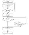
- FIG. 2 is a flowchart of determination processing.
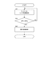
- FIG. 3 is a flowchart of the first process.
- FIG. 4 is a flowchart of the second processing.
- FIG. 5 is a flowchart of the third process.
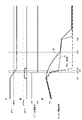
- FIG. 6 is an example of a timing chart when the first process is executed.
- FIG. 7 is an example of a timing chart when the second process is executed.
- FIG. 8 is an example of a timing chart when the third process is executed.
- FIG. 1 is a schematic configuration diagram of a vehicle 100 equipped with an automatic transmission 20 as a continuously variable transmission according to an embodiment of the invention.
- vehicle 100 includes engine 10 as a drive source, automatic transmission 20 , engine controller 30 , and transmission controller 40 .
- the automatic transmission 20 includes a torque converter 2 , a forward/reverse switching mechanism 3 , a variator 4 , a hydraulic control circuit 5 and an oil pump 6 .
- the rotation generated by the engine 10 is transmitted to the drive wheels 50 via the torque converter 2, the forward/reverse switching mechanism 3, the variator 4, the gear set 7, and the differential gear device 8.
- the torque converter 2 is provided with a lockup clutch 2a.
- the lockup clutch 2a When the lockup clutch 2a is engaged, the input shaft 2b as an input element of the torque converter 2 and the output shaft 2c as an output element are directly connected, and the input shaft 2b and the output shaft 2c rotate at the same speed. Therefore, when the lockup clutch 2a is engaged, the rotation of the output shaft 10a of the engine 10 is directly transmitted from the output shaft 2c of the torque converter 2 to the forward/reverse switching mechanism 3.
- the forward/reverse switching mechanism 3 has a double pinion planetary gear set as a main component, and its sun gear is coupled to the engine 10 via the torque converter 2, and the carrier is coupled to the input shaft 4d (primary pulley 4a) of the variator 4.
- the forward/reverse switching mechanism 3 further includes a forward clutch 3a that directly connects the sun gear and the carrier of the double pinion planetary gear set, and a reverse brake 3b that fixes the ring gear.
- the input rotation is transmitted as it is to the primary pulley 4a, and when the reverse brake 3b is engaged, the input rotation from the engine 10 via the torque converter 2 is reversely decelerated and transmitted to the primary pulley 4a.
- the variator 4 is a continuously variable transmission mechanism that changes the speed of the rotation of the engine 10 transmitted to the input shaft 4d and transmits it to the driving wheels 50 from the output shaft 4e.
- the variator 4 is an endless member that is wound around a primary pulley 4a provided on the engine 10 side, a secondary pulley 4b provided on the drive wheel 50 side, and the primary pulley 4a and the secondary pulley 4b in the power transmission path. and a belt 4c of
- the hydraulic pressure supplied to the primary pulley 4a and the hydraulic pressure supplied to the secondary pulley 4b are controlled to change the contact radii between the pulleys 4a and 4b and the belt 4c, thereby changing the gear ratio. be.
- the oil pump 6 is a mechanical oil pump that receives the rotation of the engine 10 and is driven using part of the power of the engine 10 . Oil discharged from the oil pump 6 is supplied to the hydraulic control circuit 5 .
- the hydraulic control circuit 5 includes a regulator valve 5a that adjusts the pressure of hydraulic oil supplied from the oil pump 6 to generate a required hydraulic pressure, a primary solenoid valve 5b that adjusts the hydraulic pressure supplied to the primary pulley 4a, and a secondary pulley 4b.
- a secondary solenoid valve 5c that adjusts the hydraulic pressure supplied to the lockup clutch 2a
- a lockup solenoid valve 5d that adjusts the hydraulic pressure supplied to the lockup clutch 2a, the hydraulic pressure that is supplied to the forward clutch 3a, and the hydraulic pressure that is supplied to the reverse brake 3b.
- a manual valve 5f for switching hydraulic pressure supply paths to the forward clutch 3a and the reverse brake 3b.
- the hydraulic control circuit 5 supplies the adjusted hydraulic pressure to each part of the torque converter 2 , the forward/reverse switching mechanism 3 , and the variator 4 based on the control signal from the transmission controller 40 .
- the engine controller 30 is composed of a microcomputer equipped with a CPU, RAM, ROM, input/output interface, and the like.
- the engine controller 30 performs various processes by reading and executing programs stored in the ROM by the CPU.
- the engine controller 30 can also be composed of a plurality of microcomputers.
- the engine controller 30 controls the rotation speed, torque, etc. of the engine 10 based on signals from various sensors that detect the state of each part of the vehicle 100 .
- the transmission controller 40 is composed of a microcomputer equipped with a CPU, RAM, ROM, input/output interface, etc., and is communicatively connected to the engine controller 30 .
- the transmission controller 40 performs various processes by reading and executing programs stored in the ROM by the CPU.
- the transmission controller 40 can also be composed of a plurality of microcomputers.
- the transmission controller 40 and the engine controller 30 may be integrated into one controller.
- the transmission controller 40 controls the engagement state of the lockup clutch 2a, the gear ratio of the variator 4, the engagement state of the forward clutch 3a and the reverse brake 3b, etc. based on signals from various sensors that detect the state of each part of the vehicle 100. do.
- the transmission controller 40 receives a signal from an accelerator opening sensor 61 that detects the accelerator opening APO, a signal from a brake fluid pressure sensor 62 that detects the brake fluid pressure BRP corresponding to the amount of operation of the brake pedal, and a signal from the shifter 63.
- a signal from the rotation speed sensor 67, a signal from the primary hydraulic pressure sensor 68 that detects the primary hydraulic pressure Pp supplied to the primary pulley 4a, a signal from the secondary hydraulic pressure sensor 69 that detects the secondary hydraulic pressure Ps supplied to the secondary pulley 4b, etc. are entered.
- the transmission controller 40 controls the gear ratio of the variator 4. There are various types of shift control performed by transmission controller 40 , and one is selected according to the situation of vehicle 100 .
- the shift control includes, for example, normal shift control that is executed when the vehicle 100 is considered to be driving normally, and linear shift control that is executed when the driver is thought to desire sporty driving. gear control, etc.
- Each shift control is executed using a shift map or the like set in advance based on the specifications of vehicle 100, experiments, or the like.
- the accelerator is released during execution of the linear shift control, for example, there are cases where the accelerator is released with the intention of decelerating the vehicle 100 before entering a curve, and where the driver In some cases, the accelerator is returned with the intention of ending sporty driving.
- the gear ratio should be maintained at the gear ratio immediately before the accelerator was released, or a gear ratio close thereto, in preparation for subsequent reacceleration. It can be said that it follows the intention of the person.
- maintaining the gear ratio at the gear ratio immediately before the accelerator is released or at a gear ratio close to it is not in accordance with the driver's intention. may not comply.
- the transmission controller 40 of the present embodiment performs the processing (first processing, second processing, third processing) determined by the determination processing shown in FIG. ) is executed to prevent the shift control from being executed against the driver's intention.
- FIG. 2 is a flowchart of determination processing.
- the determination process is executed when the accelerator is released while the vehicle 100 is running and the linear shift control is being executed, that is, when the accelerator opening APO becomes small.
- step S11 the transmission controller 40 determines whether the speed dAPO [deg/sec] at which the accelerator opening APO decreases is higher than the predetermined speed dAPOs.
- the predetermined speed dAPOs is a threshold at which it is considered that the driver continues to desire sporty driving when the speed dAPO is higher than the predetermined speed dAPOs.
- the predetermined speed dAPOs is set in advance based on the specifications of the vehicle 100, experiments, and the like.
- step S12 When the transmission controller 40 determines that the speed dAPO is higher than the predetermined speed dAPOs, the process proceeds to step S12. Further, when the transmission controller 40 determines that the speed dAPO is not higher than the predetermined speed dAPOs, the process proceeds to step S13.
- the transmission controller 40 determines to execute the first process.
- the first process will be described later in detail with reference to FIG.
- the transmission controller 40 determines whether the turbine rotation speed Nt is higher than the predetermined rotation speed Nts. While the vehicle 100 is traveling forward, the lockup clutch 2a and the forward clutch 3a are engaged, so the turbine rotation speed Nt, the primary rotation speed Np, and the engine rotation speed are equal.
- the predetermined rotation speed Nts is a threshold value at which the driver may continue to desire sporty driving even if the speed dAPO is not higher than the predetermined speed dAPOs.
- Predetermined rotation speed Nts is set in advance based on the specifications of vehicle 100, experiments, and the like.
- step S14 When the transmission controller 40 determines that the turbine rotation speed Nt is higher than the predetermined rotation speed Nts, the process proceeds to step S14. Further, when transmission controller 40 determines that turbine rotation speed Nt is not higher than predetermined rotation speed Nts, the process proceeds to step S15.
- the transmission controller 40 determines to execute the second process.
- the second process will be described later in detail with reference to FIG.
- the transmission controller 40 determines to execute the third process.
- the third process will be described later in detail with reference to FIG.
- FIG. 3 is a flowchart of the first process.
- the first process is executed when it is determined in the determination process that the first process is to be performed.
- the transmission controller 40 executes an upshift by linear transmission control. Specifically, an upshift is performed according to the accelerator opening APO using a shift map or the like for linear shift control.
- step S22 the transmission controller 40 determines whether the accelerator opening APO is smaller than the predetermined opening APOs.
- step S23 the transmission controller 40 determines that the accelerator opening APO is smaller than the predetermined opening APOs. Further, when the transmission controller 40 determines that the accelerator opening APO is not smaller than the predetermined opening APOs, the process returns to step S21 to continue the upshifting by the linear shift control.
- the predetermined degree of opening APOs is a threshold at which it is considered that continuation of the linear shift control in preparation for the case where the driver immediately steps on the accelerator is in line with the driver's intention.
- the predetermined opening APOs is set in advance based on the specifications of the vehicle 100, experiments, and the like.
- the transmission controller 40 ends the first process and executes gear shifting by linear shift control according to the accelerator opening APO.
- step S23 the transmission controller 40 fixes the gear ratio of the variator 4 to the gear ratio when the accelerator opening APO reaches the predetermined opening APOs.
- the engine rotation speed is maintained in a rotation speed range where a sporty feeling of acceleration can be obtained when the driver steps on the accelerator.
- the shift control is realized in accordance with the driver's desire for sporty driving.
- step S24 the transmission controller 40 determines whether the accelerator opening APO has increased.
- step S25 When the transmission controller 40 determines that the accelerator opening APO has increased, the process proceeds to step S25. Further, when the transmission controller 40 determines that the accelerator opening APO has not increased, the process proceeds to step S26.
- step S25 the transmission controller 40 performs normal gear shift control according to the accelerator opening APO.
- step S26 the transmission controller 40 determines whether or not the first predetermined time has elapsed since the gear ratio was fixed in step S23.
- the first predetermined time is set in advance based on the specifications of the vehicle 100, experiments, and the like.
- step S25 When the transmission controller 40 determines that the first predetermined time has elapsed, the process proceeds to step S25. Further, when the transmission controller 40 determines that the first predetermined time has not elapsed, the process returns to step S24.
- the shift is performed by the normal shift control. That is, starting from the gear ratio fixed in step S23, the upshift is executed along the coast line in the shift map of the normal shift control.
- FIG. 4 is a flowchart of the second processing.
- the second process is executed when it is determined in the determination process that the second process is to be performed.
- steps S31 and S32 in the second process are the same as the processes of steps S21 and S22 in the first process.
- step S33 the transmission controller 40 performs an upshift to a predetermined gear ratio, starting from the gear ratio when the accelerator opening APO reaches the predetermined opening APOs.
- the transmission controller 40 ends the second process and executes gear shifting by linear shift control according to the accelerator opening APO.
- the transmission controller 40 fixes the gear ratio at a predetermined gear ratio. In other words, the transmission controller 40 fixes the gear ratio on the Higher side than the gear ratio when the accelerator opening APO is the predetermined opening APOs.
- the predetermined gear ratio is, for example, an intermediate gear ratio between the gear ratio when the accelerator opening APO reaches the predetermined opening APOs and the gear ratio determined by the coast line in the shift map of the normal gear shift control. can be considered.
- the engine rotation speed is maintained in a rotation speed range in which a certain degree of feeling of acceleration can be obtained when the driver steps on the accelerator. Further, even when the driver intends to end the sporty driving, the engine rotation speed is maintained in a state of being reduced to about half, so that the driver can be prevented from feeling uncomfortable.
- the difference between the engine rotation speed when the accelerator opening APO reaches the predetermined opening APOs and the engine rotation speed during coasting is equal to or greater than a predetermined value.
- the predetermined value is, for example, 1000 [rpm].
- the predetermined value is considered when setting the predetermined rotation speed Nts in the determination process.
- the predetermined gear ratio is not limited to the above.
- the predetermined gear ratio may be determined, for example, using a dedicated gear shift map preset based on the specifications of the vehicle 100, experiments, and the like.
- steps S35 and S36 are the same as the processes of steps S24 and S25 in the first process.
- step S37 the transmission controller 40 determines whether the second predetermined time has elapsed since the gear ratio was fixed in step S34.
- the second predetermined time is set in advance based on the specifications of the vehicle 100, experiments, and the like.
- step S36 the transmission controller 40 determines that the second predetermined time has elapsed. Further, when the transmission controller 40 determines that the second predetermined time has not elapsed, the process returns to step S35.
- the shift is performed by the normal shift control. That is, starting from the gear ratio fixed in step S34, the upshift is executed along the coast line in the shift map of the normal shift control.
- the second predetermined time may be the same as the first predetermined time.
- FIG. 5 is a flowchart of the third process.
- the third process is executed when it is determined in the determination process that the third process is to be performed.
- steps S41 and S42 in the third process are the same as the processes of steps S21 and S22 in the first process.
- the transmission controller 40 ends the third process and executes gear shifting by linear shift control according to the accelerator opening APO.
- step S43 the transmission controller 40 executes normal gear shift control according to the accelerator opening APO.
- the third process is executed when the speed dAPO is not higher than the predetermined speed dAPOs and when the turbine rotational speed Nt is not higher than the predetermined rotational speed Nts.
- FIG. 6 is an example of a timing chart when the first process is executed.
- FIG. 7 is an example of a timing chart when the second process is executed.
- FIG. 8 is an example of a timing chart when the third process is executed.
- the accelerator is returned and then the accelerator is slightly depressed.
- the target turbine rotation speed TNt indicated by the dash-dotted line shows, as a comparative example, transition of the target turbine rotation speed TNt when the normal shift control is executed after time t12.
- the accelerator operation is started, the accelerator opening APO decreases, and the speed dAPO at which the accelerator opening APO decreases becomes higher than the predetermined speed dAPOs.
- the target turbine rotation speed TNt decreases according to the accelerator opening APO, and the turbine rotation speed Nt decreases. That is, an upshift by linear shift control is started.
- the accelerator release operation ends and the accelerator opening APO becomes zero.
- the gear ratio of the variator 4 is fixed at time t12, so the target turbine rotation speed TNt decreases as the vehicle speed decreases.
- the target turbine rotation speed TNt decreases according to the accelerator opening APO.
- the accelerator opening APO remains zero from time t13 to time t15. Therefore, after the turbine rotation speed Nt matches the target turbine rotation speed TNt at time t14, it decreases according to the vehicle speed while matching the target turbine rotation speed TNt until time t15 when the accelerator opening APO increases.
- the target turbine rotational speed TNt decreases according to the accelerator opening APO. That is, an upshift is executed under normal shift control. Ultimately, the target turbine rotation speed TNt matches the target turbine rotation speed TNt of the comparative example.
- the target turbine rotation speed TNt indicated by the dash-dotted line indicates, as a comparative example, transition of the target turbine rotation speed TNt when the normal shift control is executed after time t22.
- the accelerator release operation is started and the accelerator opening APO is decreased.
- the speed dAPO at which the accelerator opening APO becomes smaller is lower than the predetermined speed dAPOs, and the turbine rotation speed Nt is higher than the predetermined rotation speed Nts.
- the target turbine rotation speed TNt decreases according to the accelerator opening APO, and the turbine rotation speed Nt decreases. That is, an upshift by linear shift control is started.
- the gear ratio is fixed at a predetermined gear ratio.
- the accelerator release operation ends and the accelerator opening APO becomes zero.
- the gear ratio of the variator 4 is fixed at time t23, so the target turbine rotation speed TNt decreases as the vehicle speed decreases.
- the target turbine rotation speed TNt decreases according to the accelerator opening APO.
- the accelerator opening APO remains zero after time t24. Therefore, after matching the target turbine rotation speed TNt at time t25, the turbine rotation speed Nt decreases according to the vehicle speed while matching the target turbine rotation speed TNt until time t26 when the second predetermined time elapses.
- the target turbine rotation speed TNt decreases according to the accelerator opening APO. That is, an upshift is executed under normal shift control.
- the upshift is performed along the coast line in the shift map for normal shift control.
- the target turbine rotation speed TNt matches the target turbine rotation speed TNt of the comparative example.
- the vehicle 100 enters a coasting state under normal shift control.
- the accelerator release operation is started and the accelerator opening APO is decreased.
- the speed dAPO at which the accelerator opening APO becomes smaller is lower than the predetermined speed dAPOs, and the turbine rotation speed Nt is lower than the predetermined rotation speed Nts.
- the target turbine rotation speed TNt decreases according to the accelerator opening APO, and the turbine rotation speed Nt decreases. That is, an upshift by linear shift control is started.
- the target turbine rotation speed TNt decreases according to the accelerator opening APO. That is, an upshift is executed under normal shift control. As a result, the vehicle 100 enters a coasting state under normal shift control.
- the automatic transmission 20 mounted on the vehicle 100, when the accelerator opening APO decreases while the vehicle 100 is running, and when the speed dAPO at which the accelerator opening APO decreases is higher than a predetermined speed dAPOs Up to the opening APOs, an upshift is performed according to the accelerator opening APO, and the gear ratio is fixed when the accelerator opening APO is the predetermined opening APOs.
- the turbine rotation speed Nt is higher than the predetermined rotation speed Nts at a predetermined speed dAPOs or less
- an upshift is performed according to the accelerator opening APO up to the predetermined opening APOs, and the accelerator opening APO is higher than the predetermined opening APOs.
- the gear ratio is further upshifted from the gear ratio when the accelerator opening APO is the predetermined opening APOs, and the gear ratio is fixed on the Higher side than the gear ratio when the accelerator opening APO is the predetermined opening APOs.
- the speed dAPO at which the accelerator opening APO decreases is equal to or lower than a predetermined speed dAPOs and the turbine rotation speed Nt is equal to or lower than a predetermined rotation speed Nts
- an upshift is performed according to the accelerator opening APO up to the predetermined opening APOs.
- upshifting is performed according to the accelerator opening APO up to the predetermined opening APOs, and the gear ratio when the accelerator opening APO is the predetermined opening APOs is fixed. Then, a first process of maintaining the engine rotation speed in a high state, an upshift is performed according to the accelerator opening APO up to a predetermined opening APOs, and when the accelerator opening APO becomes smaller than the predetermined opening APOs, Upshifting is further performed according to the accelerator opening APO, and in the third process of lowering the engine rotation speed, upshifting is performed according to the accelerator opening APO up to a predetermined opening APOs, and the accelerator opening APO is set to a predetermined value.
- the gear ratio is further upshifted from the gear ratio when the accelerator opening APO is the predetermined opening APOs, and the gear ratio is higher than the gear ratio when the accelerator opening APO is the predetermined opening APOs. is added, it is possible to prevent the engine rotation speed from becoming too high or too low for the intention of the driver. That is, when the accelerator opening APO becomes small, it is possible to suppress execution of shift control contrary to the driver's intention.
- the automatic transmission 20 mounted on the vehicle 100 when the accelerator opening APO becomes small while the vehicle 100 is running, operates according to the accelerator opening APO up to a predetermined opening APOs.
- the gear ratio is further upshifted from the gear ratio when the accelerator opening degree APO is the predetermined opening degree APOs, and the accelerator opening degree APO becomes the predetermined opening degree APOs.
- the gear ratio is fixed on the High side of the gear ratio at , and then the gear ratio is further upshifted from the fixed gear ratio.
- the continuously variable transmission mechanism is the variator 4
- the continuously variable transmission mechanism may be another continuously variable transmission mechanism.
- Various programs executed by the transmission controller 40 may be stored in a non-transitory recording medium such as a CD-ROM.
Landscapes
- Engineering & Computer Science (AREA)
- General Engineering & Computer Science (AREA)
- Mechanical Engineering (AREA)
- Control Of Transmission Device (AREA)
Abstract
Description
20 自動変速機(無段変速機)
40 変速機コントローラ(コンピュータ)
Claims (5)
- 車両に搭載される無段変速機であって、
前記車両の走行中にアクセル開度が小さくなる場合において、
前記アクセル開度が小さくなる速度が所定速度より高い場合に、所定開度までは、前記アクセル開度に応じてアップシフトを行い、前記アクセル開度が前記所定開度のときの変速比で固定する第1処理と、
前記アクセル開度が小さくなる速度が前記所定速度以下で、タービン回転速度が所定回転速度より高い場合に、前記所定開度までは、前記アクセル開度に応じてアップシフトを行い、前記アクセル開度が前記所定開度よりも小さくなると、前記アクセル開度が前記所定開度のときの前記変速比から更にアップシフトを行って前記アクセル開度が前記所定開度のときの前記変速比よりもHigh側で前記変速比を固定する第2処理と、
前記アクセル開度が小さくなる速度が前記所定速度以下で、前記タービン回転速度が前記所定回転速度以下の場合に、前記所定開度までは、前記アクセル開度に応じてアップシフトを行い、前記アクセル開度が前記所定開度よりも小さくなると、前記アクセル開度に応じて更にアップシフトを行う第3処理と、
を有する無段変速機。 - 車両に搭載される無段変速機であって、
前記車両の走行中にアクセル開度が小さくなる場合において、
所定開度までは、前記アクセル開度に応じてアップシフトを行い、
前記アクセル開度が前記所定開度よりも小さくなると、前記アクセル開度が前記所定開度のときの変速比から更にアップシフトを行って前記アクセル開度が前記所定開度のときの前記変速比よりもHigh側で前記変速比を固定し、
その後に、固定された前記変速比から前記アクセル開度に応じて更にアップシフトを行う、
無段変速機。 - 請求項2に記載の無段変速機であって、
前記車両の走行中に前記アクセル開度が小さくなる場合において、前記アクセル開度が小さくなる速度が所定速度よりも高い場合は、
前記所定開度までは、前記アクセル開度に応じてアップシフトを行い、
前記アクセル開度が前記所定開度よりも小さくなると、前記変速比を固定する、
無段変速機。 - 車両に搭載される無段変速機の制御方法であって、
前記車両の走行中にアクセル開度が小さくなる場合において、
所定開度までは、前記アクセル開度に応じてアップシフトを行い、
前記アクセル開度が前記所定開度よりも小さくなると、前記アクセル開度が前記所定開度のときの変速比から更にアップシフトを行って前記アクセル開度が前記所定開度のときの前記変速比よりもHigh側で前記変速比を固定し、
その後に、固定された前記変速比から前記アクセル開度に応じて更にアップシフトを行う、
無段変速機の制御方法。 - 車両に搭載される無段変速機のコンピュータが実行可能なプログラムあって、
前記車両の走行中にアクセル開度が小さくなる場合において、
所定開度までは、前記アクセル開度に応じてアップシフトを行う手順と、
前記アクセル開度が前記所定開度よりも小さくなると、前記アクセル開度が前記所定開度のときの変速比から更にアップシフトを行って前記アクセル開度が前記所定開度のときの前記変速比よりもHigh側で前記変速比を固定する手順と、
その後に、固定された前記変速比から前記アクセル開度に応じて更にアップシフトを行う手順と、
を前記コンピュータに実行させるプログラム。
Priority Applications (3)
| Application Number | Priority Date | Filing Date | Title |
|---|---|---|---|
| JP2022576687A JP7526291B2 (ja) | 2021-01-19 | 2022-01-18 | 無段変速機、無段変速機の制御方法、及びプログラム |
| US18/261,884 US12146567B2 (en) | 2021-01-19 | 2022-01-18 | Continuously variable transmission, method for controlling continuously variable transmission, and non-transitory computer-readable medium |
| CN202280010571.6A CN116783414B (zh) | 2021-01-19 | 2022-01-18 | 无级变速器、无级变速器的控制方法及程序 |
Applications Claiming Priority (2)
| Application Number | Priority Date | Filing Date | Title |
|---|---|---|---|
| JP2021-006419 | 2021-01-19 | ||
| JP2021006419 | 2021-01-19 |
Publications (1)
| Publication Number | Publication Date |
|---|---|
| WO2022158448A1 true WO2022158448A1 (ja) | 2022-07-28 |
Family
ID=82549402
Family Applications (1)
| Application Number | Title | Priority Date | Filing Date |
|---|---|---|---|
| PCT/JP2022/001601 Ceased WO2022158448A1 (ja) | 2021-01-19 | 2022-01-18 | 無段変速機、無段変速機の制御方法、及びプログラム |
Country Status (4)
| Country | Link |
|---|---|
| US (1) | US12146567B2 (ja) |
| JP (1) | JP7526291B2 (ja) |
| CN (1) | CN116783414B (ja) |
| WO (1) | WO2022158448A1 (ja) |
Citations (2)
| Publication number | Priority date | Publication date | Assignee | Title |
|---|---|---|---|---|
| JP2003074682A (ja) * | 2001-08-31 | 2003-03-12 | Fuji Heavy Ind Ltd | 無段変速機の制御装置 |
| JP2012225417A (ja) * | 2011-04-19 | 2012-11-15 | Toyota Motor Corp | 車両用無段変速機の変速制御装置 |
Family Cites Families (6)
| Publication number | Priority date | Publication date | Assignee | Title |
|---|---|---|---|---|
| US5474505A (en) * | 1991-06-21 | 1995-12-12 | Dr. Ing. H.C.F. Porsche Ag | Method for controlling an automatically operated motor vehicle transmission |
| JP4726058B2 (ja) * | 2005-09-22 | 2011-07-20 | 本田技研工業株式会社 | 自動変速制御装置 |
| JP5053112B2 (ja) * | 2008-01-29 | 2012-10-17 | アイシン精機株式会社 | 自動変速機の制御装置 |
| JP5374880B2 (ja) * | 2008-02-05 | 2013-12-25 | トヨタ自動車株式会社 | 無段変速機の制御装置 |
| JP5905799B2 (ja) * | 2012-08-09 | 2016-04-20 | 本田技研工業株式会社 | 無段変速機の制御装置 |
| WO2014061563A1 (ja) * | 2012-10-15 | 2014-04-24 | ジヤトコ株式会社 | 無段変速機及びその制御方法 |
-
2022
- 2022-01-18 CN CN202280010571.6A patent/CN116783414B/zh active Active
- 2022-01-18 US US18/261,884 patent/US12146567B2/en active Active
- 2022-01-18 WO PCT/JP2022/001601 patent/WO2022158448A1/ja not_active Ceased
- 2022-01-18 JP JP2022576687A patent/JP7526291B2/ja active Active
Patent Citations (2)
| Publication number | Priority date | Publication date | Assignee | Title |
|---|---|---|---|---|
| JP2003074682A (ja) * | 2001-08-31 | 2003-03-12 | Fuji Heavy Ind Ltd | 無段変速機の制御装置 |
| JP2012225417A (ja) * | 2011-04-19 | 2012-11-15 | Toyota Motor Corp | 車両用無段変速機の変速制御装置 |
Also Published As
| Publication number | Publication date |
|---|---|
| CN116783414A (zh) | 2023-09-19 |
| US20240301950A1 (en) | 2024-09-12 |
| JPWO2022158448A1 (ja) | 2022-07-28 |
| US12146567B2 (en) | 2024-11-19 |
| CN116783414B (zh) | 2025-09-16 |
| JP7526291B2 (ja) | 2024-07-31 |
Similar Documents
| Publication | Publication Date | Title |
|---|---|---|
| JP5728422B2 (ja) | ベルト式無段変速機の変速制御装置 | |
| JP6714701B2 (ja) | 車両の制御装置及び車両の制御方法 | |
| JP2003262266A (ja) | 自動変速機の変速油圧装置 | |
| CN111868417B (zh) | 无级变速器的控制装置以及控制方法 | |
| JP7526291B2 (ja) | 無段変速機、無段変速機の制御方法、及びプログラム | |
| JP7733451B2 (ja) | 無段変速機及び無段変速機の制御方法 | |
| JP7620765B2 (ja) | 車両の制御装置、車両の制御方法、及びプログラム | |
| JP7545586B2 (ja) | 車両の制御装置、車両の制御方法、及びプログラム | |
| CN116888392B (zh) | 自动变速器、自动变速器的控制方法及程序 | |
| WO2017126475A1 (ja) | 車両の制御装置、及び車両の制御方法 | |
| JP3087869B2 (ja) | 自動変速機の変速制御装置 | |
| JP4645119B2 (ja) | 無段変速機の制御装置 | |
| JP6560758B2 (ja) | 車両の制御装置、及び車両の制御方法 | |
| JP2017137945A (ja) | 車両の制御装置、及び車両の制御方法 | |
| JP7841348B2 (ja) | 車両のエンジン始動方法及び車両のエンジン始動装置 | |
| JP4354380B2 (ja) | 無段変速機の発進時変速制御装置 | |
| JP2019203575A (ja) | 車両の制御装置及び車両の制御方法 | |
| JP4810882B2 (ja) | 自動変速機搭載車両の制御装置 | |
| JP2018114831A (ja) | 車両及び車両の制御方法 | |
| WO2025215909A1 (ja) | 車両の制御装置、車両の制御方法、及びプログラム | |
| JP2007255629A (ja) | 車両の制御装置 | |
| JP2022003258A (ja) | 車両の制御装置 | |
| JP2021032303A (ja) | 車両の制御装置及び車両の制御方法 | |
| JP2018115703A (ja) | 車両及び車両の制御方法 | |
| JPH01153856A (ja) | ベルト式無段変速機の変速制御装置 |
Legal Events
| Date | Code | Title | Description |
|---|---|---|---|
| 121 | Ep: the epo has been informed by wipo that ep was designated in this application |
Ref document number: 22742570 Country of ref document: EP Kind code of ref document: A1 |
|
| ENP | Entry into the national phase |
Ref document number: 2022576687 Country of ref document: JP Kind code of ref document: A |
|
| WWE | Wipo information: entry into national phase |
Ref document number: 18261884 Country of ref document: US Ref document number: 202280010571.6 Country of ref document: CN |
|
| NENP | Non-entry into the national phase |
Ref country code: DE |
|
| 122 | Ep: pct application non-entry in european phase |
Ref document number: 22742570 Country of ref document: EP Kind code of ref document: A1 |
|
| WWG | Wipo information: grant in national office |
Ref document number: 202280010571.6 Country of ref document: CN |