WO2022158158A1 - 電流検出装置 - Google Patents
電流検出装置 Download PDFInfo
- Publication number
- WO2022158158A1 WO2022158158A1 PCT/JP2021/045464 JP2021045464W WO2022158158A1 WO 2022158158 A1 WO2022158158 A1 WO 2022158158A1 JP 2021045464 W JP2021045464 W JP 2021045464W WO 2022158158 A1 WO2022158158 A1 WO 2022158158A1
- Authority
- WO
- WIPO (PCT)
- Prior art keywords
- detection device
- current detection
- housing
- bus bar
- shield member
- Prior art date
- Legal status (The legal status is an assumption and is not a legal conclusion. Google has not performed a legal analysis and makes no representation as to the accuracy of the status listed.)
- Ceased
Links
Images






Classifications
-
- G—PHYSICS
- G01—MEASURING; TESTING
- G01R—MEASURING ELECTRIC VARIABLES; MEASURING MAGNETIC VARIABLES
- G01R15/00—Details of measuring arrangements of the types provided for in groups G01R17/00 - G01R29/00, G01R33/00 - G01R33/26 or G01R35/00
- G01R15/14—Adaptations providing voltage or current isolation, e.g. for high-voltage or high-current networks
- G01R15/20—Adaptations providing voltage or current isolation, e.g. for high-voltage or high-current networks using galvano-magnetic devices, e.g. Hall-effect devices, i.e. measuring a magnetic field via the interaction between a current and a magnetic field, e.g. magneto resistive or Hall effect devices
-
- G—PHYSICS
- G01—MEASURING; TESTING
- G01R—MEASURING ELECTRIC VARIABLES; MEASURING MAGNETIC VARIABLES
- G01R15/00—Details of measuring arrangements of the types provided for in groups G01R17/00 - G01R29/00, G01R33/00 - G01R33/26 or G01R35/00
- G01R15/14—Adaptations providing voltage or current isolation, e.g. for high-voltage or high-current networks
- G01R15/20—Adaptations providing voltage or current isolation, e.g. for high-voltage or high-current networks using galvano-magnetic devices, e.g. Hall-effect devices, i.e. measuring a magnetic field via the interaction between a current and a magnetic field, e.g. magneto resistive or Hall effect devices
- G01R15/207—Constructional details independent of the type of device used
-
- G—PHYSICS
- G01—MEASURING; TESTING
- G01R—MEASURING ELECTRIC VARIABLES; MEASURING MAGNETIC VARIABLES
- G01R19/00—Arrangements for measuring currents or voltages or for indicating presence or sign thereof
- G01R19/0092—Measuring current only
Definitions
- the present invention relates to a current detection device that measures a current to be measured based on a magnetic field generated by the current flowing through a busbar.
- the busbar module described in Patent Document 1 when the housing is molded, the busbar may be displaced from the design position due to the influence of the flowing resin, the resin may not be properly filled (short molding), or the bent busbar may be deformed. may deform due to springback. Such defects may cause the bus bar, the magnetic sensor, and the shield to deviate from the predetermined positional relationship, which may affect the measurement accuracy.
- an object of the present invention is to provide a current detection device having a housing integrated with a busbar and a shield, and in which the measurement accuracy is less likely to deteriorate.
- a configuration is used in which a magnetic sensor is arranged at a position facing the busbar.
- the bus bar has a fastening surface with a through-hole for fastening an external terminal at the end, the fastening surface is arranged in a position overlapping the housing, and the back surface of the fastening surface contacts the nut embedded in the housing.
- the current detection device has a recess in a portion of the fastening surface of the busbar, and includes an overhang portion in which the recess is embedded in the resin of the housing, and the fastening surface of the busbar protrudes from the resin forming the overhang.
- the overhang portion it is possible to prevent the busbar from floating with respect to the nut due to springback. If the busbar floats, when the external terminal is fastened to the fastening surface with a bolt, the busbar is pressed down by the amount of the floatation, which may cause the positional relationship between the busbar and the magnetic sensor to shift. Therefore, the overhang portion is effective means for suppressing deterioration in measurement accuracy.
- the resin surface of the overhang part and the fastening surface are at the same height, when molding the housing integrally with the bus bar, the resin used to form the housing may vary due to variations in molding conditions. may flow and reach the fastening surface of the busbar. If the resin reaches the fastening surface and partially covers the fastening surface, the electrical connection between the external terminal and the busbar is damaged when the external terminal is fastened to the fastening surface.
- a further object of the present invention is to improve the electrical contact stability on the fastening surface in a configuration in which the concave portion of the fastening surface of the busbar is provided with an overhang portion embedded in the resin of the housing, thereby improving the measurement accuracy.
- the shield when the shield is insert-molded into the housing, the shield is fixed in the mold with a positioning pin. As a result, hole-shaped positioning pin traces are formed in the positions of the casing after molding where the positioning pins were arranged, and a portion of the shield is exposed inside the hole. If the side surface of the shield is used as the part that contacts the positioning pin, this side surface is exposed in the hole.
- the shield is made by punching out the outer shape of a plate material. That is, the side surface of the shield is a fractured surface (cut surface) and is not surface-treated. Therefore, if the side surface of the shield is exposed inside the hole, there is a risk of corrosion from the side surface. If corrosion occurs, it affects the magnetic properties of the shield, and there is concern that the measurement accuracy will decrease.
- a further object of the present invention is to suppress the occurrence of corrosion and ensure the measurement accuracy of the shield in a current detection device having a structure in which the shield is insert-molded into the housing, by adopting a structure in which the fractured surface, which is the side surface of the shield, is not exposed. It is an object of the present invention to provide a current detection device capable of
- the thermal expansion coefficient differs between the shield made of a metal material and the housing made of a resin material. Since the metal material has a larger coefficient of thermal expansion than the resin material, the shield tends to expand more when heat is applied. Therefore, due to the large expansion of the shield, the portion of the housing made of molded resin material (molded resin portion) that is in contact with the shield is pulled in the direction in which the shield expands more than the amount of expansion of the molded resin portion. is stressed.
- the shield and the molded resin part form a layer near the center of the shield, so the difference in the coefficient of thermal expansion greatly affects the molded resin.
- a large stress is applied to the part.
- the traces of the positioning pins become exposed holes after molding, and weld lines extending from these exposed holes (in molding, wrap around both sides of the positioning pins) V-groove-shaped lines formed at the part where the molding material that has flowed to join, etc.) are likely to be formed. Since the weld line portion is often fragile, cracks may occur along the weld line when a large stress is applied to the molded resin portion due to the difference in thermal expansion coefficient.
- the present invention suppresses cracks from occurring along the weld line even if the weld line extends from the exposure hole. It is an object of the present invention to provide a current detection device capable of
- a current detection device provides a bus bar through which a current to be measured flows, a fastening member for fastening an external member to the bus bar, and a bus bar and the fastening member that are brought into contact with each other. and a magnetic sensor arranged opposite to the bus bar and capable of detecting a magnetic field generated by the current to be measured flowing through the bus bar, and the bus bar contacts an external member on its end side.
- a current detection device provided with a fastening terminal portion that contacts an external member, and a connection surface that is a surface of the fastening terminal portion that contacts an external member is exposed from a housing, wherein the fastening terminal portion has a surface different from the connection surface It is characterized in that it has an anchor portion embedded in the housing.
- the bus bar can be prevented from floating with respect to the housing by the anchor portion. By preventing the floating, the positional relationship between the bus bar and the magnetic sensor is prevented from deviating, and good detection accuracy is maintained. Also, the electrical connection is stabilized.
- connection surface is exposed in a state of protruding from the portion of the housing that covers the anchor portion.
- the busbar has a bending portion that bends between the end portion provided with the fastening terminal portion and the opposite end portion thereof, and the magnetic sensor has a bending portion in the busbar. It is preferable to arrange so as to face a position between the portion and the fastening terminal portion. As a result, since the connection terminal connected to the external member is held by the anchor portion, even if a springback force acts on the busbar due to the bent portion, the connection terminal is less likely to be lifted. Therefore, the positional relationship between the bus bar and the magnetic sensor is less likely to shift, which contributes to improvement in measurement accuracy.
- the anchor portion is embedded in a molding made of a resin-based material included in the housing.
- Resin-based materials include a single synthetic resin, a mixture of a plurality of synthetic resins, and a mixture of fillers and the like.
- a current detection device includes a bus bar through which a current to be measured flows, a magnetic sensor arranged opposite the bus bar and capable of detecting a magnetic field generated by the current to be measured flowing through the bus bar, and the bus bar and the magnetic sensor. and a housing made of a resin-based material and integrally formed with the first shield member located on the side proximal to the busbar among the pair of shield members.
- the first shield member is characterized by comprising a substrate including a metal plate-like body, and a protective portion made of a resin-based material and covering at least a portion of an end surface of the substrate.
- the support pin is brought into contact with the position where the protection portion is located, and the mold is mounted.
- the base material is not exposed even if the first shield member is exposed on the inner surface of the hole formed in the housing where the support pin was. Therefore, it is less likely that the exposed base material will corrode and adversely affect the operation of the current sensor.
- the first shield member has an exposed portion where the base material is exposed at a location facing the busbar.
- the exposed portion is provided, the gap between the first shield member and the bus bar can be increased by the thickness of the protective portion.
- the resin-based material can be smoothly poured into and arranged appropriately, and the current detection function can be stabilized.
- the exposed portion when the exposed portion is viewed from the busbar side, the exposed portion preferably has a wide portion where the base material is exposed outside the portion overlapping the busbar. Having the wide portion makes it easier to smoothly supply the resin-based material to the gap between the busbar and the shield member.
- the substrate has an extended portion connected to the exposed portion and from which the substrate is exposed, and the protective portion is formed on the substrate such that at least the exposed portion and the extended portion are exposed. It is preferred to cover the end faces.
- the first shield member is insert-molded inside the housing, and the housing may have a hole exposing a part of the extension. preferable.
- the positioning pin of the first shield member so as to be in contact with the extended portion during insert molding, the positioning pin does not interfere with the supply of the resin-based material to the gap between the bus bar and the shield member, and the mold is improved. It is possible to improve the arrangement accuracy of the first shield member inside. By increasing the placement accuracy, the current measurement accuracy can be improved.
- a current detection device includes a plate-shaped bus bar through which a current to be measured flows, a magnetic sensor arranged opposite to the plate surface of the bus bar, and the bus bar and the magnetic sensor sandwiched from both sides in the stacking direction.
- a current detection device including a sensor unit having a pair of shield members arranged at positions and a housing made of a resin-based material molded body, wherein one of the pair of shield members is located on the proximal side of the bus bar.
- the positioned first shield member is insert-molded inside the housing, and consists of a polygonal plate-like body in a plan view, and cutout portions are formed at each of at least two corners of the polygon.
- the housing has at least one through-hole formed by the notch and partially in contact with the end surface extending in the stacking direction. This makes it possible to reduce the contact area between the support pins of the first shield member and the first shield member during insert molding. Even if it is exposed on the inner surface, since the exposed area of the end face is small, it is difficult for the end face to corrode and adversely affect the operation of the current sensor.
- the outline of the through-hole portion and the notch portion are in point contact with each other in a cross section taken along a plane parallel to the plate surface of the first shield member. is preferred. By making point contact, exposure of the end face can be reduced.
- the through hole in a cross section taken along a plane parallel to the plate surface of the first shield member, the through hole is at the same position even if the cut is made at any position in the stacking direction. It is preferable that the outline of and the notched portion are in point contact with each other. As a result, since line contact is made in the stacking direction, exposure of the end faces can be reduced.
- the notch has a plurality of end faces, and in a cross section taken along a plane parallel to the plate surface of the first shield member, the outline of the through hole is: It is preferable to make point contact with each of the plurality of end faces.
- the notch is formed to have at least two end faces, and the through hole is partially formed in each of the two or more end faces forming the notch. contact is preferred.
- the notch is formed to have two end surfaces, and the through hole can partially contact each of the two end surfaces forming the notch. preferable.
- the first shield member can be stably supported in the mold during insert molding even if there are two notches, and exposure of the end surfaces can be reduced.
- the cross-sectional shape of the through-hole portion taken along a plane parallel to the plate surface of the first shield member is circular.
- the support pin becomes a cylinder, so the contact state between the support pin and the first shield member during insert molding is likely to be stable. Therefore, the arrangement accuracy of the first shield member in the current sensor is improved, and the current measurement accuracy is likely to be improved.
- the first shield member is rectangular in plan view and has cutouts at a pair of diagonal positions, and the casing corresponds to each of the cutouts.
- a through hole is preferably provided. This facilitates dimensional control of the first shield member, and facilitates improvement in current measurement accuracy.
- the first shield member is rectangular in plan view and has notches at two pairs of diagonal positions, and the housing corresponds to each of the notches. It is preferable to have a through hole at each end. This makes it easier to improve the placement accuracy of the first shield member, and makes it easier to improve the current measurement accuracy.
- a current detection device includes a plate-shaped bus bar through which a current to be measured flows, a magnetic sensor arranged to face the plate surface of the bus bar, and the bus bar and the magnetic sensor arranged on both sides in the stacking direction.
- a current detection device including a sensor unit having a pair of shield members arranged at a position sandwiched between them, and a housing made of a resin-based material molded body, wherein the pair of shield members is closest to the bus bar.
- the first shield member located on the side is a plate-like body insert-molded inside the housing, and the housing has a plurality of sensor units along a first direction parallel to the plate surface of the first shield member.
- the housing Arranged side by side, the housing has an exposure hole through which the plate surface of the first shield member is exposed, and the exposure hole is perpendicular to the first direction and parallel to the plate surface of the first shield member in a second direction. , the plate surface located at the end of the first shield member is exposed.
- problems such as cracks along the weld line due to thermal stress are less likely to occur.
- the resin-based material flows better than in a certain area, even if the positioning pin is placed near the end of the shield member, the resin-based material is sufficiently filled around it, resulting in a weak weld line. become difficult to do. Further, when the resin-based material flows in the first direction through the gap between the first shield member and the bus bar during insert molding, there is nothing to block or divide the flow, and the resin-based material is suitable for the gap. easy to be placed in
- the first direction is orthogonal to the extending direction of the busbar. This makes it easier to set the first direction to be the longitudinal direction of the housing.
- the first shield member has the long sides of a rectangular shape in a plan view arranged along the first direction, and the exposure holes are arranged along the long sides.
- two or more are preferably arranged. This makes it easier to support the first shield member by the positioning pins during insert molding.
- the housing includes a case in which the first shield member is insert-molded, and a cover that holds the second shield member, which is the other of the pair of shield members, It is preferable that the substrate on which the magnetic sensor is mounted be fixed to the case. As a result, the pair of shield plates can be easily positioned, and a device with stable detection accuracy can be manufactured.
- a current detection device includes the current detection device according to any one of the second, third, and fourth aspects, and a fastening member for fastening an external member to a busbar, and a housing includes , the bus bar and the fastening member are held in contact with each other, the bus bar has a fastening terminal portion that contacts the external member on its end side, and the fastening terminal portion has a connection surface that contacts the external member.
- the fastening terminal section is characterized by having an anchor section that is exposed from the housing and that has a surface different from the connection surface and is embedded in the housing.
- a current detection device that includes a housing integrated with a busbar and a shield in which measurement accuracy is unlikely to deteriorate.
- the concave portion of the fastening surface of the busbar is provided with an overhang portion embedded in the resin of the housing, the electrical contact stability on the fastening surface can be improved, and the measurement accuracy is less likely to deteriorate.
- Equipment can be provided.
- the current detection device having a structure in which the shield is insert-molded into the housing by adopting a structure in which the exposure of the cross section, which is the side surface of the shield, is kept small, the occurrence of corrosion can be suppressed and the measurement accuracy of the shield can be ensured.
- a current sensing device can be provided. In addition, even if a weld line extending from the exposure hole is formed in the current detection device in which the shield member is insert-molded in the housing, it is possible to suppress the occurrence of cracks along the weld line.
- a current sensing device can be provided.
- FIG. 1(a) and 1(b) are perspective views showing the configuration of a current detection device according to a first embodiment of the present invention
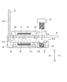
- FIG. (a) is a cross-sectional view taken along line A-A' in FIG. 1(a)
- (b) is a partially enlarged view of FIG. 2(a).
- FIG. 2 is a cross-sectional view taken along the line B-B' of FIG. 1(a);
- (a) is a figure which shows the relationship between the busbar in 1st Embodiment, and the 1st shield member corresponding to this.
- (a) is a perspective view showing the configuration of a first shield member in the first embodiment
- (b) is a perspective view showing the configuration of a base material included in the first shield member of (a).
- FIG. 2 is a cross-sectional view taken along the line C-C' of FIG. 1(a);
- (a), (b), (c), (d), and (e) are diagrams showing configurations of a fastening terminal portion and an anchor portion in a modified example of the first embodiment.
- (a) is a bottom view showing the configuration of a case in a second embodiment
- (b) is a bottom view showing the configuration of a shield member included in the case of (a). It is a bottom view which expands and shows the shield member of the left side of FIG.8(b). It is a figure which shows thermal-stress distribution of the case shown to Fig.8 (a).
- (a), (b), (c), and (d) are diagrams showing the relationship between the notch portion of the base material of the shield member and the positioning pin in the modified example of the second embodiment.
- FIG. 1 Each figure shows XYZ coordinates as reference coordinates.
- the Z1-Z2 direction is called the vertical direction
- the X1-X2 direction is called the horizontal direction
- the Y1-Y2 direction is called the front-back direction.
- the X1-X2 direction and the Y1-Y2 direction are perpendicular to each other, and the XY plane containing them is perpendicular to the Z1-Z2 direction.
- a state viewed from the upper side (Z1 side) to the lower side (Z2 side) is sometimes called a planar view.
- FIG. 1A and 1B are perspective views showing the configuration of the current detection device 10 according to the first embodiment, respectively, where (a) is a view from above (Z1 side) and (b) is a It is the figure seen from the lower side (Z2 side).
- 2(a) is a cross-sectional view taken along the line AA' of FIG. 1(a), and FIG. 2(b) is a partially enlarged view of FIG. 2(a).
- FIG. 3 is a cross-sectional view taken along line BB' of FIG. 4(a) and 4(b) are diagrams showing the relationship between the bus bar 21 and the corresponding first shield member 61 in the first embodiment, where (a) is a perspective view and (b) is a plan view.
- FIG. 5A is a perspective view showing the configuration of the first shield member 61 in the first embodiment
- FIG. 5B is a perspective view showing the configuration of the base material 161 included in the first shield member 61 of FIG. 5A.
- FIG. 6 is a cross-sectional view taken along line CC' of FIG. 1(a).
- the current detection device 10 of the first embodiment includes bus bars 21, 22, and 23 through which a current to be measured flows, and bus bars 21, 22, and 23.
- magnetic sensors 51, 52, 53 arranged opposite to the plate surfaces of plate-shaped bus bars 21, 22, 23, and bus bars 21, 22, 23;
- Three pairs of shield members (first shield members 61, 62, 63 and second shield members 71, 72, 73) sandwiching the magnetic sensors 51, 52, 53 are provided. That is, the busbar and the magnetic sensor are arranged between the first shield member and the second shield member that constitute the pair of shield members.
- the busbars 21, 22, 23 are arranged at equal intervals in the horizontal direction (X1-X2 direction), and the magnetic sensors 51, 52, 53 facing the busbars 21, 22, 23, respectively, are also arranged at equal intervals. Note that the busbars 21, 22, and 23 do not have to be arranged at regular intervals in the horizontal direction (X1-X2 direction).
- the shield members include first shield members 61, 62, and 63 located on the side closer to the busbars 21, 22, and 23, respectively, and first shield members 61, 62, and 63 located closer to the magnetic sensors 51, 52, and 53 than the busbars 21, 22, and 23. and second shield members 71, 72, and 73 positioned on each side.
- the first shield members 61, 62, 63 are arranged in the order of the first shield members 61, 62, 63 from the left side to the right side (from the X1 side to the X2 side) in FIG. 2(a).
- the second shield members 71, 72 and 73 are also arranged in the same order as the first shield from the left side to the right side (from the X1 side to the X2 side) in FIG. 2(a). It is The first shield member 61 and the second shield member 71 form a first pair, and are arranged with the magnetic sensor 51 and the bus bar 21 interposed therebetween. Similarly, the first shield member 62 and the second shield member 72 form a second pair and are arranged with the magnetic sensor 52 and the busbar 22 interposed therebetween. The first shield member 63 and the second shield member 73 form a third pair, and are arranged with the magnetic sensor 53 and the bus bar 23 interposed therebetween.
- the first pair of shield members 61 and 71 and the magnetic sensor 51 and busbar 21 sandwiched between them constitute a first sensor section.
- the second pair of shield members 62 and 72 and the magnetic sensor 52 and bus bar 22 sandwiched between them constitute a second sensor section.
- the third pair of two shield members 63 and 73 and the magnetic sensor 53 and the busbar 23 sandwiched between them constitute a third sensor section.
- the housing 40 is formed by molding a non-magnetic and insulating resin-based material, and includes a case 45 and a cover 44 that covers the upper portion of the case 45 . As shown in FIGS. 2A, 2B, and 3, second shield members 71, 72, and 73 are held by insert molding in the cover 44, and the first shield members 61, 73, and 73 are held in the case 45. 62 and 63 are held by insert molding.
- a board 50 on which magnetic sensors 51, 52 and 53 are mounted is fixed to the case 45 so that the magnetic sensors 51, 52 and 53 face the busbars 21, 22 and 23, respectively. Thereby, the magnetic field generated by the current to be measured flowing through the busbars 21, 22, and 23 facing the magnetic sensors 51, 52, and 53 can be detected by the magnetic sensors 51, 52, and 53, respectively.
- busbars 21, 22 and 23 have the same shape. 2(b), 3, 4(a), 4(b), and 6, the bus bar 21 will be described as an example, but the other bus bars 22 and 23 have the same configuration. Note that the busbars 21, 22, and 23 may have different shapes.
- the bus bar 21 has a configuration in which a plate-shaped metal member is bent in the direction of the plate thickness, and from a bent portion 21f formed by the bending, the bus bar 21 extends vertically (Z1-Z2 direction). Along with the upright portion 21u extending along, the extending portion 21v (overhang portion) extends along the front-rear direction (Y1-Y2 direction).
- a fastening terminal portion 21a is provided at the front (Y1 side) end of the extending portion 21v.
- a through-hole portion 21h is formed in the fastening terminal portion 21a so as to pass through the busbar 21 in the thickness direction (Z1-Z2 direction).
- the through hole portion 21h has a circular cross-sectional shape perpendicular to the axial direction.
- the bent portion 21f is provided between the end portion of the busbar 21 where the fastening terminal portion 21a is provided and the end portion of the busbar 21 opposite in the longitudinal direction (the upper end portion of the standing portion 21u). It is
- the magnetic sensor 51 is arranged so as to face a position between the bent portion 21f of the busbar 21 and the fastening terminal portion 21a. With this arrangement, even if springback occurs in the bent portion 21f, the extended portion 21v is held by being embedded in the housing 40, so the positional relationship with the magnetic sensor 51 is maintained. In addition, the electrical connection between the fastening terminal portion 21a and the fastening member 31 is stably maintained.
- the extended portion 21v is provided with a narrow portion 21g having a reduced width in the left-right direction at a position corresponding to the first shield member 61 when the busbar 21 is fixed to the case 45 .
- the other busbars 22 and 23 are also provided with fastening terminal portions 22a and 23a, respectively, and through hole portions 22h and 23h are provided in the same manner as the through hole portion 21h.
- the through holes 22h and 23h also have circular cross-sectional shapes perpendicular to the axial direction.
- the case 45 is provided with three protrusions 41, 42, and 43 extending forward in a plate shape.
- the protruding portions 41, 42, 43 are provided at regular intervals so as to correspond to the busbars 21, 22, 23 in the left-right direction.
- Fastening terminal portions 21a, 22a, and 23a of busbars 21, 22, and 23 are fixed to the upper portions of projecting portions 41, 42, and 43, respectively.
- Fastening members 31 , 32 , 33 for fastening bolts 34 for electrically connecting the external member M to the busbars 21 , 22 , 23 to the busbars 21 , 22 , 23 , respectively. is provided (see FIG. 3).
- the fastening member 31 is a nut provided inside the projecting portion 41, and has an inner surface 31h in which threads corresponding to the bolt 34 are formed.
- the fastening member 31 is formed so as to pass vertically through the projecting portion 41 and have a center axis along the vertical direction. Further, the fastening member 31 is provided so that the central axis of the inner surface 31h and the central axis of the through hole portion 21h of the fastening terminal portion 21a of the bus bar 21 fixed to the projecting portion 41 are aligned in the XY plane, As a result, the through holes 21h and 31h communicate with each other to form a vertically extending hole.
- the bolt 34 When the bolt 34 is inserted from the through-hole portion 21h and screwed into 31h until the bolt 34 contacts the connecting surface 21b (fastening surface), which is the surface of the fastening terminal portion 21a, the fastening terminal portion 21a of the bus bar 21 and the fastening member 31 are connected. are in contact with each other.
- the connecting surface 21b fastening surface
- the fastening terminal portion 21a of the busbar 21 is formed with an anchor portion 21e.
- the anchor portion 21e has a front end surface and two side end surfaces, in a range corresponding to the fastening member 31 in plan view, and a step is formed between the upper surface side and the lower surface side. More specifically, on the front end surface, an upper step portion 21c is formed by shifting the upper surface side rearward with respect to the lower step portion 21d on the lower surface side, and on the side end surface, another extension is formed on the lower surface side.
- An upper stepped portion 21c is formed by shifting the upper surface side inward in the horizontal direction with respect to the lower stepped portion 21d having the same width in the horizontal direction as the portion 21v.
- a plane lower than the upper surface is formed by pressing the edge of the upper surface. Therefore, in plan view, the upper step portion 21c is formed with a smaller area inside than the lower step portion 21d.
- the surface of the upper step portion 21c is common to the connection surface 21b of the fastening terminal portion 21a, and the surface of the lower step portion 21d is a different surface that is shifted vertically from the connection surface 21b.
- the fastening terminal portion 21 a is embedded in the case 45 of the housing 40 with the connecting surface 21 b protruding upward from the surface 41 a of the housing 40 .
- the upper surface of the step (lower step portion 21 d ) of the anchor portion 21 e is embedded in the case 45 of the housing 40 .
- the anchor portion 21e has the entire lower portion 21d and a portion of the upper portion 21c covered by the case 45, and the upper portion of the upper portion 21c is exposed in a state of protruding upward from the surface 41a of the case 45. is doing.
- the bus bar 21 is formed integrally with the housing 40, which is a molded body of resin material, by insert molding.
- the structure that covers the anchor portion 21e can be easily formed, and resin covering can be prevented due to the presence of a step at the boundary between the connection surface 21b and the surface 41a of the housing 40, and electrical connection with external parts can be ensured. can be realized.
- the entire lower portion 21d of the anchor portion 21e in the housing 40 it is possible to prevent the busbar 21 from floating with respect to the fastening member 31 even when springback occurs in the busbar 21. . By preventing the floating, it is possible to suppress the fluctuation of the position of the bus bar 21 with respect to the magnetic sensor 51, and obtain stable measurement accuracy.
- connection surface 21b and the surface 41a of the housing 40 were to form a continuous plane, the resin-based material of the housing 40 would seep into the connection surface 21b due to variations in molding conditions. resin fog that covers the surface may occur. Since the resin-based material has insulating properties, when the resin covering occurs, when the external component and the bus bar 21 are connected, electrical continuity cannot be obtained.
- the fastening of the busbar 21 is possible. Since the terminal portion 21 a is securely held in the housing 40 , the fastening terminal portion 21 a is less likely to be deformed, the positional relationship between the fastening terminal portion 21 a and the fastening member 31 is maintained, and the bus bar 21 is positioned relative to the magnetic sensor 51 . High-precision detection can be performed without positional fluctuation.
- the cover 44 has a hole 44a penetrating in the thickness direction (vertical direction).
- the holes 44a are formed in the second shield members 71, 72, 73, 72, 73 provided in the cover 44 so as to expose a part of extended portions (described later) of each of the second shield members 71, 72, 73 provided in the cover 44 in plan view. 4 for each of 73 are symmetrical front to back and left to right.
- the case 45 has a hole 45a penetrating in the thickness direction (vertical direction).
- the hole 45a is an extension of each of the first shield members 61, 62, and 63 provided in the case 45, for example, an extension 161c of the first shield member 61.
- Four each of the first shield members 61, 62, and 63 are arranged symmetrically in the front-back and left-right direction so as to partially expose the first shield members 61, 62, and 63.
- the hole portions 45a may have different numbers and arrangement positions for each of the first shield members 61, 62, and 63 than in the configuration described above.
- the hole 44a of the cover 44 is formed by removing positioning pins for positioning the second shield members 71, 72, and 73 during insert molding. , 62, 63 are formed after extracting the positioning pins. By performing molding using positioning pins in this way, it is possible to increase the accuracy of arrangement of the first shield members 61, 62, 63 and the second shield members 71, 72, 73 in the mold. , the current measurement accuracy can be improved.
- the first shield members 61, 62, 63 and the second shield members 71, 72, 73 have the same shape. 5A and 5B, the first shield member 61 will be described as an example, but other first shield members 62, 63 and second shield members 71, 72, 73 have the same configuration. have
- the first shield member 61 includes a base material 161 and a protective portion 261 .
- the second shield member 71 includes a base material 171 and a protective portion 271, like the first shield member 61. As shown in FIG. 5( a ), the first shield member 61 includes a base material 161 and a protective portion 261 .
- the second shield member 71 includes a base material 171 and a protective portion 271, like the first shield member 61.
- the base material 161 has a configuration in which a plurality of metal plate bodies having the same shape are stacked, and four corners of a rectangular shape in plan view are notched into rectangular shapes.
- a notch portion 161t is formed.
- the protective portion 261 is made of a resin-based material, and is arranged to cover the end surface of the notch portion 161t and the adjacent end surfaces of the end surface 161s of the base material 161.
- the protection part 261 also covers a part of the top surface and the bottom surface that are connected to the end face 161 s of the base material 161 , and has a thickness larger than that of the base material 161 in the vertical direction.
- the base material 161 by forming the base material 161 into a rectangular shape in plan view, it is possible to facilitate dimensional control and improve the current measurement accuracy.
- the management of the notching process is facilitated, and point contact with the positioning pins can be easily achieved. can be realized.
- the central portion of the base material 161 in the X1-X2 direction is not covered with the protective portion 261 and is an exposed portion 161a.
- the exposed portion 161a faces the extended portion 21v of the busbar 21.
- a wide portion 161b extending in the left-right direction is connected to the substantially central portion of the exposed portion 161a in the front-rear direction.
- the wide portion 161b is wider in the left-right direction than the opposing busbar 21, and is exposed without being covered by the busbar 21 in plan view. That is, when the exposed portion 161 a is viewed from the bus bar 21 side, the wide portion 161 b is formed to expose the base material 161 outside the portion overlapping the bus bar 21 .
- an extended portion 161c extending in the front-rear direction (Y1-Y2 direction) is connected to the substantially central portion of the exposed portion 161a in the left-right direction.
- This extended portion 161 c faces the bus bar 21 .
- the notch portion 161t which is a part of the end surface 161s of the base material 161, of the first shield member 61 is covered by the protective portion 261
- a support pin for defining the position of the first shield member 61 is brought into contact with the position where the protection part 261 is, so that the inner surface of the hole formed at the position of the support pin in the housing 40 after molding is covered with the support pin.
- the base material 161 is not exposed even if the first shield member 61 is exposed. Therefore, it is less likely that the exposed base material 161 will corrode and adversely affect the operation of the current detection device 10 .
- the protective portion 261 When forming the protective portion 261 around the base material 161 by injection molding, the position where the pointing pin for holding the base material 161 at a predetermined position in the mold was in contact with the protective portion 261 An end surface (fractured surface) of the base material 161 is exposed. However, since the first shield member 61 is insert-molded into the housing 40 , the exposed portion of the end surface (fractured surface) of the base material 161 is covered with the resin-based material of the housing 40 . Therefore, it is less likely that the exposed base material 161 will corrode and adversely affect the operation of the current detection device 10 .
- the exposed portion 161a having a smaller thickness than the protective portion 261 is arranged at a position facing the busbar 21, the gap S between the first shield member 61 and the busbar 21 (see FIG. 2B) can be taken large. For this reason, the resin-based material for insert molding can be easily introduced into the gap S, so that the resin-based material can be evenly and appropriately arranged with a predetermined thickness. Thereby, the current detection function can be stabilized.
- the first shield member 61 is provided with the wide portion 161b that is not covered with the busbar 21 and the extended portion 161c that extends to the end portion of the base material 161, the distance between the first shield member 61 and the busbar 21 The supply of the resin-based material to the gap S can be more stably performed.
- FIGS. 7A, 7B, 7C, 7D, and 7E show fastening terminal portions 101a, 111a, 121a, 131a, and 141a, anchor portions 101e, and 101e, respectively, in modifications of the first embodiment.
- FIG. 7(a) is a cross section orthogonal to the front-rear direction (Y1-Y2 direction).
- illustration of the through-holes penetrating the bus bar in the thickness direction is omitted.
- the anchor portion 21e of the first embodiment has the surfaces of the upper step portion 21c and the lower step portion 21d extending in the direction of the XY plane.
- the side surface of the upper stage portion 21c extends along the vertical direction.
- a through hole 101h that penetrates the bus bar in the thickness direction (vertical direction) is provided, and an anchor portion 101e is formed by an upper step portion 101c and a lower step portion 101d.
- the side surface of the upper step portion 101c has a tapered shape that widens outward toward the lower step portion 101d side.
- the connecting surface 101b which is the surface of the upper step portion 101c, protrudes upward from the surface 41a of the housing 40. It is embedded in the case 45, and the same effects as those of the first embodiment can be obtained.
- connection surface 111b which is the surface of the busbar, is rectangular in plan view, and the side surfaces extending from the front side and the left and right sides of the four sides of the connection surface 111b
- the anchor portion 111e has a tapered surface that widens outward toward the bottom.
- the lower range of the anchor portion 111e is embedded in the housing 40, and the connecting surface 111b is embedded in the case 45 of the housing 40 in a state of protruding upward from the surface 41a of the housing 40. .
- connection surface 121b which is the surface of the busbar, has a substantially quadrangular shape in plan view, and the upper part of the side surface 121c continuing to the left and right sides is crushed to form a concave portion 121d. It is The recess 121d and the two side surfaces 121c provided with the recess 121d form an anchor portion 121e.
- anchor portion 121e the lower region of the side surface 121c including a portion of the lower side of the recess 121d is embedded in the housing 40, and the connection surface 121b protrudes upward from the surface 41a of the housing 40. In this state, it is embedded in the case 45 of the housing 40 .
- connection surface 131b which is the surface of the bus bar, has a substantially quadrangular shape in plan view, and the upper portion of the side surface 131c connected to the front side is crushed to form a concave portion 131d.
- the recessed portion 131d and the side surface 131c provided with the recessed portion 131d constitute the anchor portion 131e.
- a lower region of the side surface 131c including a portion of the lower side of the recess 131d is embedded in the housing 40, and the connecting surface 121b protrudes upward from the surface 41a of the housing 40. In this state, it is embedded in the case 45 of the housing 40 .
- an upper step portion 141c is formed by shifting the upper surface side inward in the left-right direction with respect to the lower step portion 141d on the lower surface side, and an anchor portion 141e is formed by the upper step portion 141c and the lower step portion 141d.
- the anchor portion 141 e is embedded in the case 45 of the housing 40 such that the connection surface 141 b that is the surface of the upper step portion 141 c protrudes upward from the surface 41 a of the housing 40 .
- the base material 161 has a rectangular planar shape in plan view, but the planar shape can also be a polygonal shape other than a rectangle.
- insert molding can be performed while the shield member is accurately arranged by providing a notch in the corner and bringing the positioning pin into point contact with the end face of the notch.
- the substrate 161 In the first embodiment, four corners of the substrate 161, that is, two pairs of diagonal positions are provided with cutouts 161t. It may be a configuration in which a notch is provided in the . Moreover, even when the planar shape of the base material 161 is a polygonal shape other than a rectangle, the number of notches may be two or more as long as the base material can be accurately aligned. There may be.
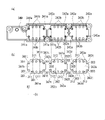
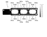
- FIG. 8A is a bottom view showing the configuration of the case 340 in the second embodiment
- FIG. 8B is a bottom view showing the configuration of the base materials 361, 362, and 363 of the shield members included in the case 340 of FIG. 8A.
- FIG. 9 is a bottom view showing an enlarged base material 361 of the shield member in FIG. 8(b).
- FIG. 10 is a diagram showing the thermal stress distribution of the case 340 shown in FIG. 8(a).
- support pins 301, 302, 303 for horizontal positioning and vertical positioning pins 311, 312, 313 are shown at the same time.
- a case 340 as a housing shown in FIG. 8A has a configuration in which base materials 361, 362, and 363 of shield members are enclosed by insert molding, similarly to the case 45 (housing 40) of the first embodiment.
- the configuration, manufacturing process, action, etc. of the case 340 described below are also applicable to the case 45 and the cover 44 of the first embodiment.
- the sensor section is formed by a pair of shield members arranged at positions sandwiching the bus bar and the magnetic sensor in the stacking direction, that is, the shield member in the cover 44 and the shield member in the case 45. , along the first direction D ⁇ b>1 that is the longitudinal direction of the case 340 .
- the extending direction of the bus bar is the same as in the first embodiment, and is a direction perpendicular to the first direction D1. Even if the number of sensor units is two or four or more, the configuration, operation, and effects of the second embodiment can be obtained.
- the base materials 361, 362, and 363 of the shield members shown in FIG. 8(b) are made of a plurality of metal plates having the same shape as the base material 161 of the first embodiment shown in FIG. 5(b). It has an overlapping configuration, and four corners of a quadrangle in plan view are cut out in a rectangular shape to form notch portions 361t. Therefore, the notch 361t has an end surface 361t1 extending along the first direction D1 and an end surface 361t2 extending along the second direction D2 (the width direction of the case 340) perpendicular to the first direction D1 (see FIG. 9). reference).
- the in-plane direction of the plane including the first direction D1 and the second direction D2 (in the direction of the paper surface of FIGS. 8A and 8B)
- Columnar support pins 301, 302, and 303 are used for positioning in the horizontal direction when the bottom surface of the case 340 is arranged along the horizontal direction.
- the four support pins 301 are in contact with the two end surfaces 361t1 and 361t2 of the four cutouts 361t. be done.
- the columnar support pin 301 has one end surface 361t1 in plan view.
- Point contact is made at point P1 and point P2 on the other end surface 361t2. This point contact is the same in a cross section taken along a plane parallel to the plate surface of the base material 361, and point contact occurs at the same position at any position in the stacking direction.
- the points P1 and P2 are vertically aligned with respect to the end surfaces 361t1 and 361t2 of the notch 361t.
- Four support pins 302 and 303 are also arranged on the central base material 362 and the right base material 363, and in plan view, point contact with the two end faces of the cutouts 362t and 363t, respectively, and Line contact is made in the thickness direction of the base materials 362 and 363 .
- a molding material made of a resin material is supplied along the first direction D1 from the left side to the right side of the paper surface.
- the case 340 has hollow cylindrical through holes 341a, 342a, and 343a penetrating to the bottom at positions where the insert-molded support pins 301, 302, and 303 were arranged. formed.
- the through holes 341a, 342a, and 343a have a circular cross-sectional shape perpendicular to the axial direction.
- the through holes 341a, 342a, 343a are formed at positions corresponding to the support pins 301, 302, 303 in shapes having corresponding outlines. Therefore, similar to the support pins 301, 302, and 303, in a cross section taken along a plane parallel to the plate surface of the base material 361, 362, and 363 of the shield member, the outline line is , 362 and 363 are in point contact with the two end faces, respectively, and are in line contact in the thickness direction of the base materials 361, 362 and 363 of the shield member.
- the contact areas between the bases 361, 362, 363 of the shield members and the support pins 301, 302, 303 during insert molding can be reduced, so that the end surfaces of the metal bases 361, 362, 363 are Even if the inner surfaces of the through holes 341a, 342a, and 343a are exposed, the exposed areas of the end surfaces of the cutouts 361t, 362t, and 363t of the base materials 361, 362, and 363 can be reduced. It is less likely that the end faces of 362t and 363t will corrode and adversely affect the operation of the current detection device.
- the base materials 361, 362, 363 and the support pins 301, 302, 303 are originally linearly exposed after molding and are covered with the resin-based material. If there is no problem caused by this, the end surfaces of the cutouts 361t, 362t, and 363t are more resistant to corrosion, so there is no problem even if the exposed portions are covered with a resin-based material.
- Cylindrical locating pins 311 , 312 , 313 are used for vertical (vertical) positioning.
- long sides 361a, 362a, and 363a of base materials 361, 362, and 363, which are rectangular in plan view, are arranged along the first direction D1, respectively.
- two columnar positioning pins 311 are in contact with both ends of the surface 361b in the second direction D2.
- the positioning pins 311 are arranged symmetrically with each other in the first direction D1 and the second direction D2.
- four positioning pins 312 and 313 are arranged on the base material 362 of the central shield member and the base material 363 of the right shield member.
- the plate surfaces of the ends of the substrates 361 , 362 , 363 in the stacking direction are Hollow cylindrical exposure holes 341b, 342b, and 343b penetrating to the bottom surface are formed to expose certain surfaces 361b, 362b, and 363b, respectively.
- the exposure holes 341b, 342b, and 343b have a circular cross-sectional shape perpendicular to the axial direction.
- regions with high thermal stress intensity are displayed in white. Regions with the lowest stress intensity are displayed in black. As can be seen from FIG. 10, the areas corresponding to the metallic substrates 361, 362, and 363 have high thermal stress intensity and are displayed in white. On the other hand, since the regions where the substrates 361, 362, and 363 are not arranged and are composed only of the resin-based material are displayed in black, it can be seen that the strength of the thermal stress is small.
- the portions where the exposure holes 341b, 342b, and 343b are formed have a degree of blackness in the periphery where the through holes are arranged compared to the central portion.
- the coefficient of thermal expansion differs between the metallic base materials 361, 362, and 363 and the case 340 (housing) made of a resin material. Therefore, when heat is applied to the case 340 , the substrates 361 , 362 , 363 expand more than the case 340 . Therefore, in the case 340, stress is less likely to be applied to regions where the base materials 361, 362, and 363 are not enclosed, that is, regions made of molded resin material.
- the peripheral regions of the ends of the substrates 361, 362, and 363, for example, the regions between the substrates 361, 362, and 363, are composed only of the molded resin portion, so the thermal expansion coefficient is different. the impact of Therefore, the stress applied to the molded resin portion is smaller than that applied to the central portions of the substrates 361 , 362 and 363 . Therefore, even if weld lines are formed extending from the exposed holes 341b, 342b, and 343b along the first direction D1, which is the supply direction of the molding material, cracks may occur along the weld lines due to thermal stress. is considered less likely to occur.
- the substrates 361, 362, and 363 are not arranged in the peripheral regions of the ends of the substrates 361, 362, and 363 in plan view compared to the regions including the substrates 361, 362, and 363,
- the resin-based material for molding flows easily. Therefore, even if the positioning pins 311, 312, and 313 are arranged at both ends of the base materials 361, 362, and 363 in the second direction D2, the resin-based material is sufficiently filled around them, so weld lines are unlikely to occur. Become.
- the substrates 361, 362, and 363 are rectangular in plan view, but the planar shape may be polygonal other than rectangular.
- cutouts are provided in the corners, and the through holes 341a, 342a, and 343a are partially brought into contact with the end faces of the cutouts, thereby enabling highly accurate positioning while minimizing exposure of the end faces. can be suppressed.
- two exposed holes 341b, 342b, 342c are arranged along each of the long sides 361a, 362a, 363a of the substrates 361, 362, 363. It may be one, or three or more.
- FIGS. 11A, 11B, 11C, and 11D show notch portions 461t of the base members 461 and 561 of the shield members in modifications (modifications 6 and 7) of the second embodiment. , 561t and positioning pins 401 and 501.
- FIG. FIG. 10(a) is a plan view showing the relationship between the notch 461t of the base material 461 and the positioning pin 401 in Modification 6,
- (b) is a sectional view taken along line DD' of (a)
- (c) is a plan view showing the relationship between the notch 561t of the base material 561 and the positioning pin 501 in Modification 7, and
- (d) is a cross-sectional view taken along line EE' of (c).
- a base material 461 which is rectangular in plan view, like the base materials 361, 362, and 363 of the second embodiment.
- a notch 461t is provided. As shown in FIG. 11(b), the notch 461t has two wedge-shaped end faces that become thinner toward the tip. forming
- the cylindrical positioning pin 401 is in line contact with the ridge line portions 461t1 and 461t2 of the notch portion 461t having such a configuration. After the base material 461 is insert-molded, a through hole is formed at a position corresponding to the positioning pin 401, as in the second embodiment. Since point contact is made, the exposure of the notch 461t can be suppressed to the ridges 461t1 and 461t2.
- the notch 461t has an end surface 561t1 extending along the first direction D1 and an end surface 561t2 extending along the second direction D2.
- a truncated conical positioning pin 501 is used, and the center axis of the positioning pin 501 is arranged along the thickness direction of the base material 561 (vertical direction in FIG. 11(d)).
- the outline of the through hole formed at the position corresponding to the positioning pin 501 makes point contact with one end face 561t1 on one line along the first direction D1, and the other end face 561t1. With respect to the end surface 561t2, point contact is made on one line along the second direction D2.
- the support pins 301, 302, and 303 are cylindrical.
- the present invention since it is necessary to pull out the support pins 301, 302, and 303 from the molded resin portion after the completion of molding, they are processed so that the diameter becomes smaller toward the tip, albeit minutely, so that they can be easily pulled out. .
- the present invention has been described with reference to the above embodiments, the present invention is not limited to the above embodiments, and can be improved or changed within the scope of the purpose of improvement or the spirit of the present invention.
Landscapes
- Physics & Mathematics (AREA)
- General Physics & Mathematics (AREA)
- Measuring Instrument Details And Bridges, And Automatic Balancing Devices (AREA)
Priority Applications (4)
| Application Number | Priority Date | Filing Date | Title |
|---|---|---|---|
| CN202180091108.4A CN116745628A (zh) | 2021-01-19 | 2021-12-10 | 电流检测装置 |
| JP2022577025A JP7471469B2 (ja) | 2021-01-19 | 2021-12-10 | 電流検出装置 |
| DE112021006854.7T DE112021006854T5 (de) | 2021-01-19 | 2021-12-10 | Stromerfassungsvorrichtung |
| US18/352,440 US12436172B2 (en) | 2021-01-19 | 2023-07-14 | Current detecting device |
Applications Claiming Priority (2)
| Application Number | Priority Date | Filing Date | Title |
|---|---|---|---|
| JP2021-006486 | 2021-01-19 | ||
| JP2021006486 | 2021-01-19 |
Related Child Applications (1)
| Application Number | Title | Priority Date | Filing Date |
|---|---|---|---|
| US18/352,440 Continuation US12436172B2 (en) | 2021-01-19 | 2023-07-14 | Current detecting device |
Publications (1)
| Publication Number | Publication Date |
|---|---|
| WO2022158158A1 true WO2022158158A1 (ja) | 2022-07-28 |
Family
ID=82549743
Family Applications (1)
| Application Number | Title | Priority Date | Filing Date |
|---|---|---|---|
| PCT/JP2021/045464 Ceased WO2022158158A1 (ja) | 2021-01-19 | 2021-12-10 | 電流検出装置 |
Country Status (5)
| Country | Link |
|---|---|
| US (1) | US12436172B2 (https=) |
| JP (1) | JP7471469B2 (https=) |
| CN (1) | CN116745628A (https=) |
| DE (1) | DE112021006854T5 (https=) |
| WO (1) | WO2022158158A1 (https=) |
Cited By (4)
| Publication number | Priority date | Publication date | Assignee | Title |
|---|---|---|---|---|
| US20220178972A1 (en) * | 2019-03-15 | 2022-06-09 | Tdk Corporation | Current sensor |
| JP2025042899A (ja) * | 2023-09-15 | 2025-03-28 | 株式会社タムラ製作所 | 電流検出器 |
| WO2025074794A1 (ja) * | 2023-10-03 | 2025-04-10 | アルプスアルパイン株式会社 | 電流センサおよび電流センサの製造方法 |
| WO2025087753A1 (de) * | 2023-10-25 | 2025-05-01 | Robert Bosch Gmbh | Schnittstellenvorrichtung für einen elektromotor oder eine e-achse eines fahrzeugs und herstellungsverfahren für eine schnittstellenvorrichtung für einen elektromotor oder eine e-achse eines fahrzeugs |
Citations (7)
| Publication number | Priority date | Publication date | Assignee | Title |
|---|---|---|---|---|
| JP2005188945A (ja) * | 2003-12-24 | 2005-07-14 | Auto Network Gijutsu Kenkyusho:Kk | 電圧降下式電流計測装置 |
| JP2005188935A (ja) * | 2003-12-24 | 2005-07-14 | Auto Network Gijutsu Kenkyusho:Kk | 電圧降下式電流計測装置 |
| JP2010078586A (ja) * | 2008-08-29 | 2010-04-08 | Yazaki Corp | 電流検出装置の組付け構造 |
| JP2016125907A (ja) * | 2015-01-05 | 2016-07-11 | トヨタ自動車株式会社 | 電流センサ |
| JP2016164523A (ja) * | 2015-03-06 | 2016-09-08 | 株式会社タムラ製作所 | 電流センサ装置 |
| WO2019117171A1 (ja) * | 2017-12-13 | 2019-06-20 | アルプスアルパイン株式会社 | 電流センサ及び電流センサのケースの製造方法 |
| US20200292589A1 (en) * | 2019-03-14 | 2020-09-17 | Te Connectivity Germany Gmbh | Passive current sensor with simplified geometry |
Family Cites Families (15)
| Publication number | Priority date | Publication date | Assignee | Title |
|---|---|---|---|---|
| US7381101B2 (en) * | 2006-08-25 | 2008-06-03 | Lear Corporation | Battery post connector |
| JP5228679B2 (ja) * | 2008-07-31 | 2013-07-03 | 住友電装株式会社 | 電流センサーを備えた電気接続箱 |
| JP5414333B2 (ja) | 2009-04-09 | 2014-02-12 | 矢崎総業株式会社 | 電流検出装置の組付け構造 |
| JP5872758B2 (ja) * | 2010-04-28 | 2016-03-01 | 矢崎総業株式会社 | 電流検出装置 |
| JP5464098B2 (ja) * | 2010-08-23 | 2014-04-09 | 住友電装株式会社 | 電流検出装置 |
| JP5690209B2 (ja) * | 2011-05-17 | 2015-03-25 | Tdk株式会社 | 電流センサ |
| JP2013015425A (ja) * | 2011-07-05 | 2013-01-24 | Sumitomo Wiring Syst Ltd | 電流検出装置 |
| JP6262579B2 (ja) * | 2014-03-20 | 2018-01-17 | 矢崎総業株式会社 | 電流センサーと導電部材との組み付け構造 |
| JP6477089B2 (ja) | 2014-05-23 | 2019-03-06 | 株式会社デンソー | 電流センサ付バスバーモジュール |
| JP6149885B2 (ja) * | 2015-03-18 | 2017-06-21 | トヨタ自動車株式会社 | 電流センサ |
| JP6402089B2 (ja) | 2015-12-02 | 2018-10-10 | アルプス電気株式会社 | 電流センサ |
| JP2018185230A (ja) * | 2017-04-26 | 2018-11-22 | 株式会社デンソー | 電流センサ |
| JP6973221B2 (ja) | 2018-03-20 | 2021-11-24 | 株式会社デンソー | 電流センサ |
| JP6890112B2 (ja) * | 2018-11-15 | 2021-06-18 | 矢崎総業株式会社 | 電流検出装置 |
| JP7138138B2 (ja) | 2020-06-16 | 2022-09-15 | 株式会社コロプラ | プログラム、情報処理方法及び情報処理装置 |
-
2021
- 2021-12-10 WO PCT/JP2021/045464 patent/WO2022158158A1/ja not_active Ceased
- 2021-12-10 JP JP2022577025A patent/JP7471469B2/ja active Active
- 2021-12-10 DE DE112021006854.7T patent/DE112021006854T5/de active Pending
- 2021-12-10 CN CN202180091108.4A patent/CN116745628A/zh active Pending
-
2023
- 2023-07-14 US US18/352,440 patent/US12436172B2/en active Active
Patent Citations (7)
| Publication number | Priority date | Publication date | Assignee | Title |
|---|---|---|---|---|
| JP2005188945A (ja) * | 2003-12-24 | 2005-07-14 | Auto Network Gijutsu Kenkyusho:Kk | 電圧降下式電流計測装置 |
| JP2005188935A (ja) * | 2003-12-24 | 2005-07-14 | Auto Network Gijutsu Kenkyusho:Kk | 電圧降下式電流計測装置 |
| JP2010078586A (ja) * | 2008-08-29 | 2010-04-08 | Yazaki Corp | 電流検出装置の組付け構造 |
| JP2016125907A (ja) * | 2015-01-05 | 2016-07-11 | トヨタ自動車株式会社 | 電流センサ |
| JP2016164523A (ja) * | 2015-03-06 | 2016-09-08 | 株式会社タムラ製作所 | 電流センサ装置 |
| WO2019117171A1 (ja) * | 2017-12-13 | 2019-06-20 | アルプスアルパイン株式会社 | 電流センサ及び電流センサのケースの製造方法 |
| US20200292589A1 (en) * | 2019-03-14 | 2020-09-17 | Te Connectivity Germany Gmbh | Passive current sensor with simplified geometry |
Cited By (4)
| Publication number | Priority date | Publication date | Assignee | Title |
|---|---|---|---|---|
| US20220178972A1 (en) * | 2019-03-15 | 2022-06-09 | Tdk Corporation | Current sensor |
| JP2025042899A (ja) * | 2023-09-15 | 2025-03-28 | 株式会社タムラ製作所 | 電流検出器 |
| WO2025074794A1 (ja) * | 2023-10-03 | 2025-04-10 | アルプスアルパイン株式会社 | 電流センサおよび電流センサの製造方法 |
| WO2025087753A1 (de) * | 2023-10-25 | 2025-05-01 | Robert Bosch Gmbh | Schnittstellenvorrichtung für einen elektromotor oder eine e-achse eines fahrzeugs und herstellungsverfahren für eine schnittstellenvorrichtung für einen elektromotor oder eine e-achse eines fahrzeugs |
Also Published As
| Publication number | Publication date |
|---|---|
| CN116745628A (zh) | 2023-09-12 |
| US20240019465A1 (en) | 2024-01-18 |
| JPWO2022158158A1 (https=) | 2022-07-28 |
| US12436172B2 (en) | 2025-10-07 |
| DE112021006854T5 (de) | 2023-11-16 |
| JP7471469B2 (ja) | 2024-04-19 |
Similar Documents
| Publication | Publication Date | Title |
|---|---|---|
| WO2022158158A1 (ja) | 電流検出装置 | |
| CN101939886B (zh) | 接线块 | |
| US20100227514A1 (en) | Conductive Contact and Conductive Contact Unit | |
| US7142264B2 (en) | Unit for receiving a display module, display module and display apparatus having the same | |
| CN116359555A (zh) | 电连接装置 | |
| JP5817508B2 (ja) | 電流検出装置 | |
| US12050235B2 (en) | Heat dissipatable die unit and probe seat using the same | |
| JP2009026464A (ja) | 基板と端子材の接続構造 | |
| US10297734B2 (en) | LED module | |
| WO2019117171A1 (ja) | 電流センサ及び電流センサのケースの製造方法 | |
| US20090298307A1 (en) | Conductive Contact Unit and Conductive Contact | |
| US7389691B2 (en) | Acceleration sensor | |
| JP6238161B2 (ja) | 電池集合体と導電路付き端子との接続構造 | |
| JP2017112349A (ja) | コイル組立体および回路構成体 | |
| JP2011124193A (ja) | 台座コネクタ | |
| JP5577040B2 (ja) | プローブカード | |
| JP4228939B2 (ja) | 電気接続箱の製造方法 | |
| JP4388932B2 (ja) | 電気的接続装置 | |
| JP2010278831A (ja) | 水晶片集合基板 | |
| JP2020004494A (ja) | 遮蔽板を有する電気コネクタ、及び、該電気コネクタのハウジングの製造方法 | |
| JP2006003252A (ja) | 電気的接続装置 | |
| JP4781938B2 (ja) | 導電性接触子ユニット | |
| JP2017084927A (ja) | コイル組立体および電気接続箱 | |
| JP5329301B2 (ja) | 多芯コネクタ | |
| CN103490202B (zh) | 连接器 |
Legal Events
| Date | Code | Title | Description |
|---|---|---|---|
| 121 | Ep: the epo has been informed by wipo that ep was designated in this application |
Ref document number: 21921260 Country of ref document: EP Kind code of ref document: A1 |
|
| ENP | Entry into the national phase |
Ref document number: 2022577025 Country of ref document: JP Kind code of ref document: A |
|
| WWE | Wipo information: entry into national phase |
Ref document number: 202180091108.4 Country of ref document: CN |
|
| WWE | Wipo information: entry into national phase |
Ref document number: 112021006854 Country of ref document: DE |
|
| 122 | Ep: pct application non-entry in european phase |
Ref document number: 21921260 Country of ref document: EP Kind code of ref document: A1 |