WO2022153786A1 - 流体機械 - Google Patents
流体機械 Download PDFInfo
- Publication number
- WO2022153786A1 WO2022153786A1 PCT/JP2021/046688 JP2021046688W WO2022153786A1 WO 2022153786 A1 WO2022153786 A1 WO 2022153786A1 JP 2021046688 W JP2021046688 W JP 2021046688W WO 2022153786 A1 WO2022153786 A1 WO 2022153786A1
- Authority
- WO
- WIPO (PCT)
- Prior art keywords
- pump rotor
- fluid machine
- chamber
- motor
- shaft
- Prior art date
- Legal status (The legal status is an assumption and is not a legal conclusion. Google has not performed a legal analysis and makes no representation as to the accuracy of the status listed.)
- Ceased
Links
Images


Classifications
-
- F—MECHANICAL ENGINEERING; LIGHTING; HEATING; WEAPONS; BLASTING
- F04—POSITIVE - DISPLACEMENT MACHINES FOR LIQUIDS; PUMPS FOR LIQUIDS OR ELASTIC FLUIDS
- F04C—ROTARY-PISTON, OR OSCILLATING-PISTON, POSITIVE-DISPLACEMENT MACHINES FOR LIQUIDS; ROTARY-PISTON, OR OSCILLATING-PISTON, POSITIVE-DISPLACEMENT PUMPS
- F04C29/00—Component parts, details or accessories of pumps or pumping installations, not provided for in groups F04C18/00 - F04C28/00
- F04C29/12—Arrangements for admission or discharge of the working fluid, e.g. constructional features of the inlet or outlet
Definitions
- the disclosure in this specification relates to a fluid machine.
- Patent Document 1 discloses a fluid machine used as a negative pressure pump.
- Patent Document 2 discloses a thru-vane type fluid machine.
- Patent Document 1 has room for improvement in reducing defects related to bearings caused by differential pressure.
- the purpose of disclosure in this specification is to provide a fluid machine that can ensure the quality of bearings.
- the purpose of the disclosure in this specification is to provide a thru-vane type fluid machine capable of suppressing machine loss.
- One of the disclosed fluid machines is a pump rotor that rotates inside the housing, driven by a housing (32, 24, 31; 124; 132), a motor unit (2), and a driving force provided by the motor unit. (6; 106; 206), a suction chamber (71) provided inside the housing, through which the working fluid from the outside flows into the inside of the housing via the external suction passage (70), and the suction chamber.
- a compression chamber (73) that compresses and discharges the supplied working fluid as the pump rotor rotates, and a motor that is shielded from the suction chamber inside the housing so that the working fluid does not flow.
- the motor chamber (241) in which the portion is housed and the bearing portion (212) that rotatably supports the shaft (21) that transmits the driving force of the motor portion to the pump rotor are provided, and the bearing portion is a suction chamber. Has a part exposed to.
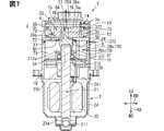
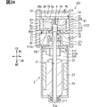
- FIG. 6 is a vertical cross-sectional view of the pump rotor at the XXVII-XXVII cross-sectional position of FIG. 26. It is a top view of the pump rotor seen toward the discharge chamber side. It is a vertical sectional view of the fluid machine which concerns on 6th Embodiment. It is a vertical sectional view of the fluid machine which concerns on 7th Embodiment. It is a vertical sectional view of the fluid machine which concerns on 8th Embodiment.
- the fluid machine includes a pump section that compresses the fluid.
- the fluid machine 1 disclosed in the first embodiment can compress a liquid, a gas, a gas-liquid mixed fluid or the like adopted as a working fluid and let it flow out to the outside.
- the working fluid is air, water, various refrigerants, and the like.
- the fluid machine 1 is not a device for driving the working fluid in a closed loop circuit, for example, but supplies the working fluid flowing out of the fluid machine 1 to the open outside.
- the fluid machine 1 is a vane type fluid machine provided with a vane that extends so as to penetrate the pump rotor 6 and slides in the radial direction.
- the fluid machine 1 is preferably an oilless type device that can normally function without receiving oil supply from the outside.
- the fluid machine 1 can eliminate the need for an accessory device such as an oil separator.
- the fluid machine 1 can also be applied as an air pressure source for supplying clean air, such as medical air and factory air. An example in which the fluid machine 1 uses air as the working fluid will be described below.
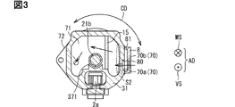
- the configuration of the fluid machine 1 will be described with reference to FIG.
- RD indicates the radial direction
- AD indicates the axial direction of the shaft 21
- MS indicates the motor unit 2 side
- BS indicates the discharge chamber 75 side.
- the fluid machine 1 shown in FIG. 1 includes a motor unit 2, a pump unit 3, and the like.
- the pump unit 3 includes a compression chamber 73 partitioned in the circumferential direction by a cylinder 32, a pump rotor 6, a plurality of vanes, and the like.
- the pump unit 3 forms an area in which the working fluid flows in the fluid machine 1 except for the motor unit 2.
- the compression chamber 73 compresses and discharges the working fluid supplied through the suction chamber 71 as the pump rotor 6 rotates.
- the fluid machine 1 includes a housing integrally formed by a plurality of members.
- the fluid machine 1 includes a motor yoke 24, a suction chamber case 31, a cylinder 32, and a cover 33 to form a housing.
- the motor yoke 24 and the suction chamber case 31 are combined to form a part of the housing.
- the suction chamber case 31 and the motor yoke 24 are fixed by bolting or welding.
- the suction chamber case 31 includes a bearing support portion 34.
- the bearing support portion 34 includes a portion that supports the second bearing portion 212 and an annular plate portion that separates the motor chamber 241 and the suction chamber 71.
- the suction chamber case 31 and the cylinder 32 are integrally formed via the first plate 35.
- the suction chamber case 31 is integrated with the first plate 35 in a sealed state because the end portion of the tubular body is coupled to the first plate 35 with the gasket 11 interposed therebetween.
- the cylinder 32 is integrated with the first plate 35 in a sealed state because the end portion of the tubular body is coupled to the first plate 35 with the gasket 12 interposed therebetween.
- the gasket 11 and the gasket 12 suppress the outflow of the working fluid from the pump chamber to the outside air and the inflow of gas or foreign matter from the outside air.
- the cylinder 32 and the cover 33 are integrally formed via the second plate 36.
- the cylinder 32 is integrated with the second plate 36 in a sealed state because the end portion of the tubular body is coupled to the second plate 36 with the gasket 13 interposed therebetween.
- the cover 33 is integrated with the second plate 36 in a sealed state because the end portion of the tubular body is coupled to the second plate 36 with the gasket 14 interposed therebetween.
- the suction chamber case 31, the first plate 35, the cylinder 32, the second plate 36, and the cover 33 are fixed by, for example, bolting or welding. These members are installed so as to be laminated in the axial direction AD of the shaft 21 to form a housing.
- the suction chamber case 31, the first plate 35, the cylinder 32, the second plate 36, and the cover 33 are installed so that their outer walls are exposed to the atmosphere.
- These members may have a structure in which at least a part thereof is made of a metal having good thermal conductivity.
- These members may be configured so that at least a part thereof is exposed to the atmosphere. According to this configuration, the heat generated in the sliding portion due to the rotation of the pump rotor 6 is diffused through the outer wall and released to the outside atmosphere of the fluid machine 1.
- the suction chamber case 31 is a part of the housing in the fluid machine 1.
- the suction chamber case 31 forms a suction chamber 71 inside which the working fluid is sucked.
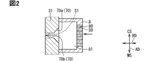
- the suction chamber case 31 is provided with an external suction passage 70 for sucking the working fluid flowing out from the external device into the suction chamber 71.
- the external suction passage 70 is a passage that penetrates the suction chamber case 31 in the radial direction, and is an inlet portion that takes in the working fluid inside the fluid machine 1.
- the external suction passage 70 includes a first passage 70a and a second passage 70b located downstream of the first passage 70a.
- the first passage portion 70a is formed in a mortar shape having the largest passage cross-sectional area in the uppermost stream portion and a smaller passage cross-sectional area toward the downstream.
- the first passage portion 70a formed in this way contributes to suppressing fluid noise during suction while suppressing suction resistance.
- the passage cross-sectional area in this specification is the area of the cross section orthogonal to the passage axis direction.
- the passage cross-sectional area of the second passage portion 70b is smaller than the average passage cross-sectional area of the first passage portion 70a, and is equivalent to the passage cross-sectional area at the most downstream of the first passage portion 70a.
- the passage cross-sectional area of the second passage portion 70b is set to S1.
- the external suction passage 70 constitutes a passage having a smaller passage cross-sectional area on the downstream side than on the upstream side.
- An introduction member 8 forming a passage communicating with the external suction passage 70 is integrally fixed to the suction chamber case 31.
- the introduction member 8 is connected to a pipe forming a passage leading to an external device.
- the introduction member 8 includes a plurality of pores 80 and a chamber 81 formed on the downstream side of the plurality of pores 80.
- the passage formed by the pores 80 is set to S0, which has a passage cross-sectional area smaller than that of S1.
- the chamber 81 is formed to have a larger passage cross-sectional area than the pores 80 and the external suction passage 70.
- the working fluid from the external device is diverted by the pores 80, diffused into the chamber 81, further squeezed by the first passage portion 70a and the second passage portion 70b, and then spread in the suction chamber 71. That is, the fluid machine 1 suppresses the pressure pulsation on the suction side by repeating contraction and expansion when the working fluid flows through the introduction member 8, the external suction passage 70, and the suction chamber 71. Further, the plurality of pores 80 suppress the blockage of the external suction passage 70 by foreign matter from the outside.
- the cross-sectional area of the suction chamber 71 immediately after the working fluid flows into the external suction passage 70 is set to S2.
- the cross-sectional area S2 is the cross-sectional area of a plane orthogonal to the radial direction RD.
- This cross section is a cross section at the position where the length of the axial AD is the longest in the suction chamber 71.
- the cross section having the area S2 and the cross section having the area S1 are planes parallel to each other.
- FIG. 5 shows the theoretical equation R and the model of the theoretical transmission loss related to pulsation attenuation.
- the transmission loss is also called the pulsation attenuation amount.
- the theoretical formula can be calculated from the drawing ratio m, which is the ratio of the passage cross-sectional area S2 to the passage cross-sectional area S1, and the length l of the suction chamber.
- m is the ratio of the passage cross-sectional area S2 to the passage cross-sectional area S1
- the length l of the suction chamber In order to attenuate the low frequency around the pulsation frequency of 250 Hz, it is preferable to form the fluid machine 1 so as to increase the aperture ratio m and the length l. Further, in order to obtain an attenuation effect of 5 dB or more in the vicinity of a frequency of 250 Hz, it is preferable to form the fluid machine 1 so that the aperture ratio m is 16 or more.
- the passage cross-sectional area S0 of the pore 80 is preferably small in order to suppress inhalation pulsation, but there is a trade-off relationship with the pressure loss. Since the pressure loss at the time of suction is preferably 10 kPa or less, in the fluid machine 1, the passage cross-sectional area of the external suction passage 70 is set so as to obtain such a pressure loss.
- a filter 15 is provided inside the suction chamber case 31 between the external suction passage 70 and the shaft 21.
- the filter 15 is provided in the suction side area of the suction chamber 71.
- the filter 15 is a device that captures foreign matter contained in the working fluid on the upstream side of the compression chamber 73, and suppresses performance deterioration due to malfunction, corrosion, etc. due to the foreign matter.
- the filter 15 is made of a porous material.
- the filter 15 is formed of, for example, a filter medium such as a woven fabric of fibers or a non-woven fabric.
- the filter 15 includes, for example, a net unit set to an aperture ratio that does not allow foreign matter to pass through, and a frame unit that supports the net unit.
- the net unit is formed of, for example, polypropylene or nylon 66
- the frame unit is formed of, for example, polypropylene or nylon 66 reinforced with glass fiber.
- the fluid machine 1 includes a motor terminal 2a that supplies electric power to the motor unit 2.
- the motor terminal 2a is provided in the suction chamber case 31 on the outer diameter of the suction chamber 71 and the second bearing portion 212.
- the first plate 35 is provided with a compression chamber introduction passage 72 that communicates the suction chamber 71 and the compression chamber 73.
- the compression chamber introduction passage 72 is a passage that penetrates the first plate 35 in the axial direction AD, and is a passage that draws the working fluid from the suction chamber 71 into the compression chamber 73.
- the first plate 35 is a passage forming member provided with a compression chamber introduction passage 72. As shown in FIG. 4, the compression chamber introduction passage 72 is elongated in the circumferential direction and forms an opening having a shape along the inner peripheral surface 32a of the cylinder 32.
- the suction chamber 71 is formed to include a suction side area and an outflow side area.
- the suction side area is an area that occupies half of the suction chamber 71 on the side where the external suction passage 70 is located with respect to the shaft 21.
- the outflow side area is an area that occupies half of the suction chamber 71 on the side opposite to the suction side area.
- the suction side area and the outflow side area may have the same volume, or one may have a larger volume than the other.
- the compression chamber introduction passage 72 is a passage provided in the suction chamber 71 at a position facing the outflow side area.
- the suction side area is an area corresponding to the entire side of the suction chamber 71 shown in FIG. 3 on which the external suction passage 70 is located from the central axis of the shaft 21 when viewed in the axial direction of the shaft 21.
- the outflow side area is an area corresponding to the entire side of the suction chamber 71 shown in FIG. 3 on which the compression chamber introduction passage 72 is located from the central axis of the shaft 21 when viewed in the axial direction of the shaft 21.
- the external suction passage 70 and the compression chamber introduction passage 72 having such a positional relationship contribute to the diffusion of the working fluid in the suction chamber 71 and the circulation over a wide area.
- the compression chamber introduction passage 72 is located in the outflow side area including a range in which the external suction port is rotated 180 degrees or more in the circumferential direction CD with the shaft 21 as the center.
- the compression chamber introduction passage 72 is a passage that penetrates the wall portion facing the area including this range in the outflow side area.
- the external suction passage 70 and the compression chamber introduction passage 72 are preferably provided in such a positional relationship so that the working fluid can be widely distributed in the suction chamber 71.
- the working fluid flowing into the suction chamber 71 flows around the shaft 21, passes through the shaft 21, moves to the outflow side area, changes the flow in the axial direction, and reaches the compression chamber introduction passage 72.
- the suction chamber 71 When the suction chamber 71 has a fan shape having a circumferential length of less than 180 degrees around the shaft 21, the central angles of the suction side area and the outflow side area are less than 90 degrees.
- the suction chamber 71 When the suction chamber 71 has a ring shape centered on the shaft 21 when viewed in the axial direction, the suction side area and the outflow side area are semicircular with a central angle of 180 degrees or less.
- the cover 33 includes a base portion and a cylindrical wall protruding in the axial direction AD so as to surround the base portion from the peripheral portion of the base portion.
- the base portion of the cover 33 is provided with a discharge port 76 that penetrates in the axial direction AD.
- the discharge port 76 is an external outflow passage for discharging the fluid to the outside of the fluid machine 1.
- the tubular wall of the cover 33 is in contact with the second plate 36 and is supported by sandwiching the second plate 36 with the cylinder 32.
- the space surrounded by the cover 33 and the second plate 36 forms a discharge chamber 75 communicating with the discharge port 76.
- a filter 16 is provided in the discharge chamber 75.
- the filter 16 is a member capable of collecting wear debris and the like generated by sliding between the fixed member and the pump rotor 6.
- the filter 16 is made of a porous material.
- the filter 16 is a member in which a porous material is formed into a predetermined shape.
- the filter 16 is formed of, for example, a filter medium such as a woven fabric of fibers or a non-woven fabric.
- the second plate 36 is provided with a discharge chamber introduction passage 74 that communicates the discharge chamber 75 and the compression chamber 73.
- the discharge chamber introduction passage 74 is a passage that penetrates the second plate 36 in the axial direction AD, and is a passage that discharges the working fluid from the compression chamber 73 to the discharge chamber 75.
- the discharge chamber introduction passage 74 is elongated in the circumferential direction and forms an opening having a shape along the inner peripheral surface 32a of the cylinder 32.
- the discharge chamber introduction passage 74 and the compression chamber introduction passage 72 are provided so that the central axis of the pump rotor 6 is located between them and faces each other in the radial direction.
- the cylinder 32, the pump rotor 6, and the vane constitute a compression mechanism for sucking in, compressing, and discharging the working fluid.
- a cylindrical pump rotor 6 is provided inside the cylindrical cylinder 32.
- a plurality of compression chambers 73 are formed between the outer peripheral surface 6c of the pump rotor 6 and the inner peripheral surface 32a of the cylinder 32.
- the central axis of the pump rotor 6 is provided at a position deviated from the central axis of the cylinder 32. With this configuration, the pump rotor 6 rotates at a position closer to one side inside the cylinder 32.
- a plurality of vanes 4 are slidably mounted on the pump rotor 6.
- the vane 4 slides in the radial direction while being fitted in the slit 6s formed in the pump rotor 6.
- the tip portion on the outer diameter of the vane 4 slides with respect to the inner peripheral surface 32a of the cylinder 32 as the pump rotor 6 rotates.
- Each of the plurality of compression chambers 73 is formed between vanes 4 and vanes 4 adjacent to each other in the circumferential direction.
- the compression chamber 73 is partitioned by a vane 4, an inner peripheral surface 32a of the cylinder 32, an outer peripheral surface 6c of the pump rotor 6, a first plate 35, and a second plate 36.
- the space between the outer peripheral surface 6c and the inner peripheral surface 32a is narrower.
- a compression chamber 73 narrower than the other portions is formed between the narrowed outer peripheral surface 6c and the inner peripheral surface 32a.
- the fluid machine 1 has three compression chambers 73 arranged in the circumferential direction.
- the fluid machine 1 has a narrow compression chamber 73 and a wide compression chamber 73 located on the opposite side of the narrow compression chamber 73.
- the narrow compression chamber 73 is formed in a portion where the outer peripheral surface 6c is close to the inner peripheral surface 32a.
- the wide compression chamber 73 is formed at a portion where the outer peripheral surface 6c is largely separated from the inner peripheral surface 32a.
- the plurality of compression chambers 73 move in the circumferential direction as the pump rotor 6 rotates.
- the pump rotor 6 includes a supported portion 61 that is in contact with and supported by the connecting portion 37.
- the connecting portion 37 is a member that connects the pump rotor 6 and the shaft 21.
- the supported portion 61 is a tubular portion that forms an inner peripheral surface that penetrates in the axial direction and has a predetermined axial length.
- the connecting portion 37 is press-fitted into the inner peripheral surface of the supported portion 61, and the connecting portion 37 and the supported portion 61 are fitted to each other.
- the pump rotor 6 is provided with a slit 6s in which the vane 4 is fitted.
- the slit 6s has an elongated cross-sectional shape extending in a direction intersecting the radial direction of the pump rotor 6, and is a plate-like body extending in the axial direction.
- a curved surface is formed at the tip of the vane 4.
- the pump rotor 6 is provided with an engaging hole portion that forms a hole that penetrates in the axial direction. As shown in FIGS. 1 and 4, the engaging hole portion is in contact with the inserted drive pin 64.
- the drive pin 64 engages with the engagement hole 6d to support the pump rotor 6.
- the drive pin 64 has a motor side portion, which is an end portion on the motor portion 2 side, fixed to the pedestal portion 373.
- the pedestal portion 373 is coaxially coupled to the connecting portion 37 and is provided coaxially with the shaft 21.
- the pedestal portion 373 and the connecting portion 37 rotate integrally with the shaft 21 as the shaft 21 rotates.
- the pedestal portion 373 drives the pump rotor 6 via the drive pin 64. With this configuration, the pedestal portion 373, the connecting portion 37, and the pump rotor 6 are integrally rotated by the shaft 21.
- the shaft 21 is a driving unit that applies a rotational driving force to the pump rotor 6.
- the suction chamber case 31, the cylinder 32, the first plate 35, the second plate 36, and the cover 33 can be formed of metal, resin, or the like.
- the pump rotor 6 is made of a stainless steel material.
- the first plate 35 and the second plate 36 have a coating of polytetrafluoroethylene provided on a sliding surface that slides on the pump rotor 6.
- the pump rotor 6 may be made of carbon, and the first plate 35 and the second plate 36 may be made of a stainless steel material. According to such a configuration, it contributes to ensuring the sliding performance under the non-lubricating condition where the lubricating oil is not supplied from the outside.
- the cylinder 32 is a part of the housing in the fluid machine 1.
- the cylinder 32 is made of a stainless steel material.
- the vane 4 is preferably formed of carbon. According to this configuration, it contributes to suppress wear and seizure between the tip of the vane 4 and the inner peripheral surface of the cylinder 32, and is useful in the fluid machine 1 used under the condition of no lubrication.
- the suction chamber case 31 is integrally provided with a motor unit 2 on the side opposite to the cylinder 32 side.
- the suction chamber case 31 forms a suction chamber 71 inside.
- the motor yoke 24 is integrated with the suction chamber case 31 in a sealed state because the end portion of the tubular body is coupled to the suction chamber case 31 with the gasket 10 interposed therebetween.
- the motor yoke 24 is a part of the housing in the fluid machine 1.
- the motor unit 2 has a stator, a motor rotor 22, a shaft 21, and the like provided inside the motor yoke 24.
- the motor unit 2 is housed in the motor chamber 241.
- the motor chamber 241 is partitioned by a bearing support portion 34 and a second bearing portion 212 so as to shut off from the suction chamber 71.
- the motor chamber 241 is maintained at atmospheric pressure because it is blocked from the flow path of air, which is a working fluid, from the suction chamber 71 to the discharge port 76. Therefore, there is no positive inflow of outside air into the motor chamber 241 and the fluid machine 1 contributes to the suppression of corrosion of the motor portion 2 due to the humidity caused by the outside air. Further, since no differential pressure is generated between the pump rotor side end surface 212a and the motor side end surface 212b of the second bearing portion 212, grease leakage from the second bearing portion 212 can be suppressed.
- the shaft 21 is rotatably provided by a first bearing portion 211 provided inside the motor yoke 24 and a second bearing portion 212 supported by the bearing support portion 34.
- the first bearing portion 211 supports one end shaft portion 21a of the shaft 21.
- the second bearing portion 212 supports a portion of the shaft 21 closer to the motor rotor 22 than the other end shaft portion 21b.
- the second bearing portion 212 is a bearing portion that is located inside the suction chamber case 31 and rotatably supports the shaft 21 that transmits the driving force of the motor portion 2 to the pump rotor 6.
- the stator, motor rotor 22, and the like are located in the motor chamber 241 formed inside the motor yoke 24.
- the motor chamber 241 is formed by an internal space surrounded by a motor yoke 24, a bearing support portion 34, and a second bearing portion 212.
- the motor chamber 241 is a space portion adjacent to the suction chamber 71 via the bearing support portion 34.
- the bearing support portion 34 contacts the outer peripheral portion of the second bearing portion 212 and supports the second bearing portion 212.
- the second bearing portion 212 has a pump rotor side end surface 212a located on the pump rotor 6 side and a motor side end surface 212b located on the motor rotor 22 side.
- the pump rotor side end surface 212a and the motor side end surface 212b are located at positions facing each other in the axial direction of the shaft 21, and each forms an annular surface around the axis of the shaft 21.
- the end face 212a on the pump rotor side is exposed to the suction chamber 71 and may come into contact with the working fluid flowing through the suction chamber 71.
- the motor side end surface 212b is not exposed to the suction chamber 71 and does not come into contact with the working fluid.
- the second bearing portion 212 has a portion exposed to the suction chamber 71 including the end surface 212a on the pump rotor side.
- the shaft 21 is rotationally driven by the driving force given by the motor unit 2.
- the connecting portion 37 and the pump rotor 6 are separate parts.
- the connecting portion 37, the pump rotor 6 and the shaft 21 are arranged coaxially and are rotationally driven integrally.
- the other end shaft portion 21b of the shaft 21 is coupled to the connecting portion 37.
- the connecting portion 37 includes a one-sided coupling portion 371 that couples to the shaft 21, and a pair of other-side support portions 372 that support the pump rotor 6.
- the one-side coupling portion 371 is located on the motor portion 2 side in the connecting portion 37.
- the pair of other side support portions 372 are located on the discharge chamber 75 side in the connecting portion 37.
- the other end shaft portion 21b is closely bonded to the inner wall surface of the one side coupling portion 371.
- the one-side coupling portion 371 forms a cylindrical portion that wraps the other end shaft portion 21b from the outside, and is coaxially fixed to the other end shaft portion 21b.
- the one-side coupling portion 371 is located in the suction chamber 71.
- the central axis of the shaft 21 is the rotation axis of the pump rotor 6.
- the shaft 21 is a drive shaft portion that rotates the pump rotor 6 via the drive pin 64.
- the pump rotor 6 rotates in the cylinder 32 with an arcuate seal portion closest to the inner peripheral surface 32a and a separating portion largely separated from the inner peripheral surface 32a of the outer peripheral surface 6c.
- the fluid machine 1 forms a narrow compression chamber 73 on the arc-shaped seal portion side and a wide compression chamber 73 on the separation portion side.
- the narrow compression chamber 73 moves in the direction of rotation while the vane 4 rotates, and expands as it approaches the separated portion to change into a wide compression chamber 73.
- the wide compression chamber 73 moves in the rotational direction while the vane 4 rotates, and shrinks as it approaches the arcuate seal portion to change into a narrow compression chamber 73.
- each compression chamber 73 changes so that its volume gradually decreases while approaching the discharge chamber introduction passage 74 while the vane 4 makes one rotation.
- the air supplied to the compression chamber 73 through the compression chamber introduction passage 72 is compressed, and this air is discharged from the discharge chamber introduction passage 74 to the discharge chamber 75.
- Air which is the working fluid in the fluid machine 1, flows down in the order of the external suction passage 70, the suction chamber 71, the compression chamber introduction passage 72, and the compression chamber 73.
- the air flows down from the compression chamber 73 in the order of the discharge chamber introduction passage 74 and the discharge chamber 75, and flows out from the discharge port 76 to the outside.
- air cools each part and contributes to effectively releasing heat of the sliding part in particular.
- the fluid machine 1 which is the first modification includes a first seal portion 17 which contacts and seals the shaft 21 and the bearing support portion 34.
- the first seal portion 17 is in contact with the outer peripheral surface of the shaft 21, and is sandwiched between the pump rotor side end surface 212a of the second bearing portion 212 and the bearing support portion 34.
- the first seal portion 17 prevents the working fluid of the suction chamber 71 from entering the motor chamber 241 through between the outer peripheral surface of the shaft 21 and the inner peripheral surface of the second bearing portion 212.
- the first seal portion 17 prevents the working fluid of the suction chamber 71 from entering the motor chamber 241 through between the bearing support portion 34 and the second bearing portion 212.
- the first seal portion 17 is formed of a resin containing fluorine, a rubber packing, or the like.
- the fluid machine 1 as a second modification includes a second sealing portion 18 that contacts and seals the connecting portion 37 and the first plate 35.
- Each part of the connecting part 37 with which the second seal part 18 comes into contact is included in the drive shaft part for driving the pump rotor 6.
- the second seal portion 18 is in contact with the outer peripheral surface of the drive shaft portion penetrating the first plate 35, and is in contact with the inner peripheral surface forming the through hole 350 in the first plate 35.
- the second seal portion 18 prevents the working fluid of the compression chamber 73 from leaking to the suction chamber 71 through between the pump rotor 6 and the first plate 35.
- the second seal portion 18 prevents the working fluid from moving back and forth between the inside of the cylinder 32 and the suction chamber 71 without passing through the compression chamber introduction passage 72.
- the second seal portion 18 is formed of a resin containing fluorine, a rubber packing, or the like.
- the fluid machine 1 which is the third modification includes a third sealing portion 19 which contacts and seals the pump rotor 6 and the first plate 35.
- the third seal portion 19 is sandwiched between the first plate 35 and the pump rotor 6.
- the third seal portion 19 seals between the surface 35a on the discharge chamber side of the first plate 35 and the surface 6b on the motor portion side of the pump rotor 6.
- the third seal portion 19 seals between the first plate 35 and the pump rotor 6 in a state where the pump rotor 6 and the first plate 35 are relatively slidable.
- the third seal portion 19 prevents the working fluid of the compression chamber 73 from leaking to the suction chamber 71 through between the pump rotor 6 and the first plate 35.
- the third seal portion 19 prevents the working fluid from moving back and forth between the inside of the cylinder 32 and the suction chamber 71.
- the third seal portion 19 is formed of a resin containing fluorine, a rubber packing, or the like.
- the fluid machine 1 which is the fourth modification includes a cylindrical wall portion 341 extending from the bearing support portion 34 toward the compression chamber side.
- the cylindrical wall portion 341 is erected at a position closer to the compression chamber than the pump rotor side end surface 212a of the second bearing portion 212, and covers the second bearing portion 212 on the outer diameter of the second bearing portion 212.
- the cylindrical wall portion 341 is provided with a communication passage 340 through which a working fluid can flow between an area in contact with the end surface 212a on the pump rotor side and an area outside the diameter of the tubular wall portion 341.
- the communication passage 340 may be formed by the axial end faces of the tubular wall portion 341, or may be configured to penetrate the tubular wall portion 341.
- the tubular wall portion 341 functions as a shielding wall that prevents foreign matter from coming into contact with the second bearing portion 212 and causing a problem with the flow of the working fluid flowing through the suction chamber 71. Further, when the working fluid is air, the cylindrical wall portion 341 can prevent the second bearing portion 212 from being exposed to the moisture contained in the air sucked into the suction chamber 71.
- the fluid machine 1 which is the fourth modification includes a motor case 124, a suction chamber case 131, a cylinder 32, and a cover 33 to form a housing.
- the motor case 124 and the suction chamber case 131 are integrally connected via a bearing support member 134.
- the bearing support member 134 includes a support portion 34a that supports the second bearing portion 212, and an annular plate portion that extends outward in diameter from the outer peripheral portion of the support portion 34a.
- the annular plate portion of the bearing support member 134 is coupled to the motor case 124 and the suction chamber case 131 in a sandwiched state.
- the fluid machine 1 includes a motor unit 2, a pump rotor 6 that is rotated inside the housing by a driving force of the motor unit 2, and a suction chamber 71 into which working fluid flows in through an external suction passage 70.
- the fluid machine 1 includes a compression chamber 73 that compresses and discharges the working fluid supplied through the suction chamber 71, a motor chamber 241 in which the motor portion is housed, and a bearing portion.
- the motor chamber 241 is provided inside the housing so as to be shielded from the suction chamber 71 so that the working fluid does not flow.
- the bearing portion rotatably supports the shaft 21 that transmits the driving force of the motor portion 2 to the pump rotor 6.
- the bearing portion has a portion exposed to the suction chamber 71.
- the working fluid sucked into the suction chamber 71 from the outside comes into contact with the bearing portion. Due to this action, it is difficult to apply a large differential pressure to the bearing portion, and it is possible to suppress a situation in which grease leakage or the like occurs in the bearing portion due to an excessive differential pressure.
- the fluid machine 1 can ensure the quality of the bearing portion. Further, since the motor chamber 241 has a structure in which the working fluid does not flow, it contributes to suppressing corrosion of each part of the motor part 2.
- the compression chamber introduction passage 72 is provided at a position facing the outflow side area in the suction chamber 71. According to this, since the compression chamber introduction passage 72 and the external suction passage 70 are located so as to have the shaft 21 in between, it contributes to the suppression of the suction pulsation sound while suppressing the enlargement of the fluid machine 1.
- the compression chamber introduction passage 72 is located in an area of the outflow side area including a range in which the external suction passage 70 is rotated 180 degrees or more in the circumferential direction CD with the shaft 21 as the center. According to this, the maximum separation distance between the compression chamber introduction passage 72 exposed to the suction chamber 71 and the external suction passage 70 can be set as large as possible. Therefore, it is possible to provide the fluid machine 1 that contributes to the suppression of the inhalation pulsating sound while suppressing the increase in size.
- the fluid machine 1 is a device used under non-lubricating conditions where no lubricating oil is supplied from the outside. According to this, it is possible to provide the fluid machine 1 which can suppress the mechanical loss between the pump rotor 6 and the peripheral members due to the displaceable characteristics of the pump rotor 6 and also contribute to the prevention of seizure when no lubrication is applied.
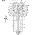
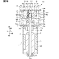
- the second embodiment will be described with reference to FIGS. 11 to 18.
- the fluid machine 101 of the second embodiment is different from the first embodiment in that it is a through-vane type fluid machine.
- the configurations, actions, and effects that are not particularly described in the second embodiment are the same as those in the above-described embodiment, and only the differences will be described below.
- the fluid machine 101 includes a vane that extends through the central axis of the pump rotor 106 and penetrates the pump rotor 106 and slides in the radial direction of the pump rotor 106.
- the fluid machine 101 is preferably an oilless type device that can normally function without receiving oil supply from the outside.
- the fluid machine 101 can eliminate the need for an accessory device such as an oil separator.
- the fluid machine 101 can also be applied as an air pressure source for supplying clean air, such as medical air or factory air. An example in which the fluid machine 101 uses air as the working fluid will be described below.
- the configuration of the fluid machine 101 will be described with reference to FIG. 11 includes a motor unit 2, a pump unit 3, and the like.
- the pump unit 3 includes a compression chamber 73 partitioned in the circumferential direction by a cylinder 32, a pump rotor 106, a plurality of vanes, and the like.
- the pump unit 3 forms an area in which the working fluid flows in the fluid machine 101 except for the motor unit 2.
- the fluid machine 101 includes a housing integrally formed by a plurality of members.
- the fluid machine 101 includes a motor case 124, a suction chamber case 131, a cylinder 32, and a cover 33 to form a housing.
- the motor case 124 and the suction chamber case 131 are integrally formed via a plate-shaped bearing support member 134.
- the suction chamber case 131 and the cylinder 32 are integrally formed via the first plate 35.
- the bearing support member 134, the suction chamber case 131, the first plate 35, the cylinder 32, the second plate 36, and the cover 33 are fixed by bolting or welding. These parts are installed so as to be laminated in the axial direction AD of the shaft 21 to form a housing.
- the suction chamber case 131, the first plate 35, the cylinder 32, the second plate 36, and the cover 33 are installed so that their outer walls are exposed to the atmosphere.
- These parts may be configured such that at least a part thereof is made of a metal having good thermal conductivity.
- These parts need only be configured so that at least a part of them is exposed to the atmosphere. According to this configuration, the heat generated in the sliding portion due to the rotation of the pump rotor 106 is diffused through the outer wall and released to the outside atmosphere of the fluid machine 101.
- the suction chamber case 131 forms a suction chamber 71 inside which the working fluid is sucked.
- the suction chamber case 131 is provided with an external suction passage 70 for sucking the working fluid flowing out from the external device into the suction chamber 71.
- the external suction passage 70 is a passage that penetrates the suction chamber case 131 in the radial direction, and is an inlet portion that takes in the working fluid inside the housing.
- the discharge chamber introduction passage 74 and the compression chamber introduction passage 72 are provided so that the central axis of the pump rotor 106 is located between them and faces each other in the radial direction.
- the cylinder 32, the pump rotor 106, the first vane 104, and the second vane 5 form a compression mechanism for sucking, compressing, and discharging the working fluid.
- a cylindrical pump rotor 106 is provided inside the cylindrical cylinder 32.
- a plurality of compression chambers 73 are formed between the outer peripheral surface 6c of the pump rotor 106 and the inner peripheral surface 32a of the cylinder 32.
- the central axis of the pump rotor 106 is provided at a position deviated from the central axis of the cylinder 32. With this configuration, the pump rotor 106 rotates at a position closer to one side inside the cylinder 32.
- the second vane 5 and the first vane 104 are slidably mounted on the pump rotor 106 in a posture orthogonal to each other.
- Each of the first vane 104 and the second vane 5 slides in the radial direction while being fitted in the slit formed in the pump rotor 106.
- the tip portion 42b on the outer diameter of the first vane 104 slides with respect to the inner peripheral surface 32a of the cylinder 32 as the pump rotor 106 rotates.
- the tip portion 52b on the outer diameter of the second vane 5 slides with respect to the inner peripheral surface 32a of the cylinder 32 as the pump rotor 106 rotates.
- Each of the plurality of compression chambers 73 is formed between the second vane 5 and the first vane 104 adjacent to each other in the circumferential direction.
- the compression chamber 73 is partitioned by a second vane 5, a first vane 104, an inner peripheral surface 32a of the cylinder 32, an outer peripheral surface 6c of the pump rotor 106, a first plate 35, and a second plate 36.
- a compression chamber 73 narrower than the other portions is formed between the narrowed outer peripheral surface 6c and the inner peripheral surface 32a.
- the fluid machine 101 has four compression chambers 73 arranged in the circumferential direction.
- the fluid machine 101 has two narrow compression chambers 73 and two wide compression chambers 73 located on opposite sides of the two narrow compression chambers 73.
- the two narrow compression chambers 73 are formed in a portion where the outer peripheral surface 6c is close to the inner peripheral surface 32a.
- the two wide compression chambers 73 are formed at a portion where the outer peripheral surface 6c is largely separated from the inner peripheral surface 32a.
- the four compression chambers 73 move in the circumferential direction as the pump rotor 106 rotates.
- the configuration of the pump rotor 106 will be described with reference to FIGS. 12, 13, 14, and 15.
- the pump rotor 106 includes a supported portion 61 that is in contact with and supported by the connecting portion 137.
- the connecting portion 137 is a member that connects the pump rotor 106 and the shaft 21.
- the supported portion 61 is a tubular portion that forms an inner peripheral surface that penetrates in the axial direction and has a predetermined axial length.
- the connecting portion 137 is not press-fitted into the inner peripheral surface of the supported portion 61 but is partially in contact with the connecting portion 137, and the connecting portion 137 and the supported portion 61 are fitted to each other.
- the pump rotor 106 includes a one-sided cylindrical portion 62 located closer to the motor portion 2 than the supported portion 61, and a other-side tubular portion 63 located closer to the discharge chamber 75 than the supported portion 61. ..
- the inner peripheral surface of the one-side tubular portion 62 and the inner peripheral surface of the other-side tubular portion 63 are formed so as to have an inner diameter larger than the inner peripheral surface of the supported portion 61.
- the pump rotor 106 has a penetrating portion that is axially penetrated by a one-sided cylindrical portion 62, a supported portion 61, and the other-side tubular portion 63.
- the pump rotor 106 is provided with a first slit 6sa1, a second slit 6sa2, a third slit 6sb1 and a fourth slit 6sb2.
- the first slit 6sa1 and the second slit 6sa2 are slits into which the first vane 104 is fitted.
- the third slit 6sb1 and the fourth slit 6sb2 are slits into which the second vane 5 fits.
- the first slit 6sa1 and the second slit 6sa2 are provided at positions rotated by 90 degrees with respect to the third slit 6sb1 and the fourth slit 6sb2 in the pump rotor 106.
- the first slit 6sa1 and the second slit 6sa2 are continuous and form a U-shaped slit that is convex on the discharge chamber 75 side.
- the third slit 6sb1 and the fourth slit 6sb2 are continuous and form a convex U-shaped slit on the motor portion 2 side.
- the first slit 6sa1 is a slit on the discharge chamber 75 side of the pump rotor 106 that passes through the central axis of the pump rotor 106 and penetrates the entire diameter of the pump rotor 106.
- the first slit 6sa1 is a one-side slit extending in the radial direction of the pump rotor through the central axis of the pump rotor 106 on one side of the supported portion 61 in the axial direction.
- the first slit 6sa1 extends through the central axis to the outer peripheral surface 6c in the pump rotor 106.
- the second slit 6sa2 is a slit that is connected to each of both ends of the first slit 6sa1 and penetrates the pump rotor 106 in the axial direction on the motor portion 2 side of the pump rotor 106.
- the second slit 6sa2 is a slit provided so as not to pass through the central axis of the pump rotor 106.
- the second slit 6sa2 is a slit on the other side extending axially from both radial ends of the slit on the other side of the supported portion 61.
- the pump rotor 106 is provided with a pair of second slits 6sa2 on the outer peripheral surface 6c side of the pump rotor 106.
- the first slit 6sa1 and the second slit 6sa2 penetrate from the surface 6a on the discharge chamber side of the pump rotor 106 to the surface 6b on the motor portion side on the outer peripheral surface 6c side of the pump rotor 106.
- the surface 6a on the discharge chamber side and the surface 6b on the motor portion side are end faces facing each other and orthogonal to each other in the axial direction in the pump rotor 106.
- the third slit 6sb1 is a slit on the motor portion 2 side of the pump rotor 106 that passes through the central axis of the pump rotor 106 and penetrates the entire diameter of the pump rotor 106.
- the third slit 6sb1 is a one-sided slit extending in the radial direction of the pump rotor through the central axis of the pump rotor 106 on one side of the supported portion 61 in the axial direction.
- the third slit 6sb1 extends through the central axis to the outer peripheral surface 6c in the pump rotor 106.
- the fourth slit 6sb2 is a slit connected to each of both ends of the third slit 6sb1 and axially penetrates the pump rotor 106 on the discharge chamber 75 side of the pump rotor 106.
- the fourth slit 6sb2 is a slit provided so as not to pass through the central axis of the pump rotor 106.
- the fourth slit 6sb2 is a slit on the other side extending axially from both radial ends of the slit on the other side of the supported portion 61.
- the pump rotor 106 is provided with a pair of fourth slits 6sb2 on the outer peripheral surface 6c side of the pump rotor 106.
- the third slit 6sb1 and the fourth slit 6sb2 penetrate from the surface 6a on the discharge chamber side of the pump rotor 106 to the surface 6b on the motor portion side on the outer peripheral surface 6c side of the pump rotor 106.
- the second vane 5 is a U-shaped plate-shaped member that is convex toward the motor portion 2.
- the second vane 5 includes a radial extension portion 51 elongated in the radial direction on the motor portion 2 side, and a pair of axial extension portions 52 extending axially from both ends of the radial extension portion 51.
- the radial extension 51 is elongated in the radial direction with respect to the axial direction, and has a radial length longer than the outer diameter dimension of the pump rotor 106.
- the radial extension 51 has an axial length that is smaller or equivalent to the axial length of the third slit 6sb1.
- the second vane 5 is provided so that the motor side end portion 51a, which is the end on the motor portion side of the radial extension portion 51, is along the surface 6b on the motor portion side.
- the motor side end portion 51a may be configured to slide with respect to the surface 35a on the discharge chamber side of the first plate 35 as the pump rotor 106 rotates.
- the axial extension portion 52 has a radial length from the tip portion 52b on the outer diameter to the end portion 52c on the inner diameter.
- the radial length of the axial extension portion 52 is equivalent to the radial length of the fourth slit 6sb2.
- the second vane 5 is provided so that the discharge chamber side end portion 52a, which is the discharge chamber side end of the axial extension portion 52, is along the discharge chamber side surface 6a.
- the discharge chamber side end portion 52a may be configured to slide with respect to the surface 36a of the second plate 36 on the motor portion side as the pump rotor 106 rotates.
- the second vane 5 is provided so that the outer-diameter tip 52b, which is the outer-diameter end of the axially extending portion 52, is along the outer peripheral surface 6c.
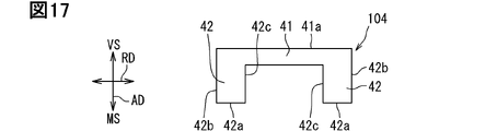
- the first vane 104 is a U-shaped plate-shaped member that is convex toward the discharge chamber 75 side.
- the first vane 104 includes a radially elongated radial extension 41 on the discharge chamber 75 side, and a pair of axial extension 42 extending axially from both ends of the radial extension 41.
- the radial extension 41 is elongated in the radial direction with respect to the axial direction, and has a radial length longer than the outer diameter dimension of the pump rotor 106.
- the radial extension 41 has an axial length that is smaller or equivalent to the axial length of the first slit 6sa1.
- the first vane 104 is provided so that the discharge chamber side end 41a, which is the discharge chamber side end of the radial extension 41, is along the discharge chamber side surface 6a.
- the discharge chamber side end portion 41a may be configured to slide with respect to the surface 36a of the second plate 36 on the motor portion side as the pump rotor 106 rotates.
- the axial extension portion 42 has a radial length from the tip portion 42b on the outer diameter to the end portion 42c on the inner diameter.
- the radial length of the axial extension portion 42 is equivalent to the radial length of the second slit 6sa2.
- the first vane 104 is provided so that the motor side end portion 42a, which is the end on the motor portion side of the axial extension portion 42, is along the surface 6b on the motor portion side.
- the motor side end portion 42a may be configured to slide with respect to the surface 35a on the discharge chamber side of the first plate 35 as the pump rotor 106 rotates.
- the first vane 104 is provided so that the outer-diameter tip 42b, which is the outer-diameter end of the axially extending portion 42, is along the outer peripheral surface 6c.
- the pump rotor 106 is provided with an engaging hole portion 6d that forms a hole that penetrates in the axial direction. As shown in FIG. 18, the engaging hole portion 6d is in contact with the inserted drive pin 64.
- the drive pin 64 supports the pump rotor 106 at the engaging portion 64b that engages with the engaging hole portion 6d.
- the motor side portion 64a which is the end portion on the motor portion 2 side, is fixed to the pedestal portion 373.
- the pedestal portion 373 is coaxially coupled to the connecting portion 137 and is provided coaxially with the shaft 21.
- the pedestal portion 373 and the connecting portion 137 rotate integrally with the shaft 21 as the shaft 21 rotates.
- the pedestal portion 373 drives the pump rotor 106 via the drive pin 64. With this configuration, the pedestal portion 373, the connecting portion 137, and the pump rotor 106 are integrally rotated by the shaft 21.
- the shaft 21 is a driving unit that applies a rotational driving force to the pump rotor 106.
- the pump rotor 106 has a non-supporting portion 6e on the motor side that is not supported apart from the driving pin 64 on the motor portion side of the engaging hole portion 6d.
- the pump rotor 106 has a non-support portion 6f on the discharge chamber side that is not supported apart from the drive pin 64 on the discharge chamber side with respect to the engagement hole portion 6d.
- the engaging portion 64b contributes to contacting the pump rotor 106 at a position close to the central portion in the axial direction.
- the pump rotor 106 may have some backlash in the rotational direction. Therefore, a gap between the radial extension portion 51 and the facing surface 372a is set so that the pair of other side support portions 1372 and the radial extension portion 51 do not interfere with each other.
- the suction chamber case 131, cylinder 32, first plate 35, second plate 36, and cover 33 can be formed of metal, resin, or the like.
- the pump rotor 106 is made of a stainless steel material.
- the first plate 35 and the second plate 36 have a coating of polytetrafluoroethylene provided on a sliding surface that slides on the pump rotor 106.
- the pump rotor 106 may be made of carbon, and the first plate 35 and the second plate 36 may be made of a stainless steel material. According to this, it contributes to ensuring the sliding performance under the non-lubricating condition where the lubricating oil is not supplied from the outside.
- the first vane 104 and the second vane 5 are preferably formed of carbon. According to this configuration, it contributes to suppressing wear and seizure between the tip of the vane and the inner peripheral surface of the cylinder 32. This configuration is useful in the fluid machine 101 used under non-lubricated conditions.
- the suction chamber case 131 is integrally provided with a motor unit 2 on the side opposite to the cylinder 32 side.
- the suction chamber case 131 forms a suction chamber 71 inside.
- the motor case 124 is integrally fixed to the bearing support member 134 so that the end portion of the tubular body is coupled to the bearing support member 134.
- the motor case 124 is also a yoke in the motor unit 2.
- the motor case 124 is a part of the housing in the fluid machine 101.
- the motor unit 2 has a stator 23, a motor rotor 22, a shaft 21, and the like provided inside the motor case 124.
- the stator 23 covers the outer circumference of the motor rotor 22.
- various motors such as a brushed motor and a brushless motor can be adopted.
- the shaft 21 is rotatably provided by a first bearing portion 211 provided inside the motor case 124 and a second bearing portion 212.
- the second bearing portion 212 is supported by the support portion 34a of the bearing support member 134.
- the second bearing portion 212 is located inside the suction chamber case 131.
- the stator 23, the motor rotor 22, and the like are located in the motor chamber 241 formed inside the motor case 124.
- the motor chamber 241 is formed by an internal space surrounded by a motor case 124, a bearing support member 134, and a second bearing portion 212.
- the motor chamber 241 is a space portion adjacent to the suction chamber 71 via the bearing support member 134.
- the support portion 34a of the bearing support member 134 contacts the outer peripheral portion of the second bearing portion 212 to support the second bearing portion 212.
- the second bearing portion 212 has a pump rotor side end surface 212a located on the pump rotor 106 side and a motor side end surface 212b located on the motor rotor 22 side.
- the motor side end surface 212b is not exposed to the suction chamber 71 and does not come into contact with the working fluid.
- the connecting portion 137 and the pump rotor 106 are separate parts.
- the connecting portion 137, the pump rotor 106, and the shaft 21 are arranged coaxially and are rotationally driven integrally.
- the other end shaft portion 21b of the shaft 21 is coupled to the connecting portion 137.
- the connecting portion 137 includes a one-sided coupling portion 371 that couples to the shaft 21, and a pair of other-side support portions 1372 that support the pump rotor 106.
- the one-side coupling portion 371 is located on the motor portion 2 side in the connecting portion 137.
- the pair of other side support portions 1372 are located on the discharge chamber 75 side in the connecting portion 137.
- the other side support portion 1372 has a facing surface 372a along the axial direction and the radial direction.
- the pair of other side support portions 1372 face each other with a predetermined interval in the radial direction RD.
- the predetermined interval corresponds to the distance between the facing surface 372a and the facing surface 372a in the pair of other side support portions 1372.
- the pair of other side support portions 1372 form a support portion in which the discharge chamber 75 side is open.
- the pair of other side support portions 1372 form support portions having an opening on the outer diameter.
- a radial extension portion 51 of the second vane 5 extending in the radial direction is interposed between the pair of other side support portions 1372.
- the radial extension 51 and the facing surface 372a are separated from each other.
- the radial extension 51 may slide between the pair of other side supports 1372 during rotation of the pump rotor 106.
- the pump rotor 106 is in contact with the outer peripheral surface of the other side support portion 1372 in the supported portion 61, and is not in contact with the connecting portion 137 in the portion other than the supported portion 61.
- the other side support portion 1372 supports the supported portion 61 so that the pump rotor 106 and the connecting portion 137 can move relatively in the axial direction. Further, the other side support portion 1372 supports the supported portion 61 so that the connecting portion 137 and the pump rotor 106 can be tilted relative to the axial center of the shaft 21.
- the pair of other side support portions 1372 has a fixed end on the motor portion 2 side and a free end on the discharge chamber 75 side. Due to this cantilever structure, the other side support portion 1372 can be bent so as to move in the radial direction. This bending action contributes to supporting the supported portion 61 so that it can be tilted relative to the shaft 21.
- the other side support portion 1372 and the supported portion 61 are integrally connected so as to be relatively axially movable and / or tiltable.
- the other side support portion 1372 and the supported portion 61 may be fitted so as to be relatively axially movable and / or tiltable.
- the other side support portion 1372 and the supported portion 61 may have a connection structure in which a part of the support portion 1372 and the supported portion 61 are in contact with each other and the rest is separated so as to be relatively movable in the axial direction and / or tiltable. .. It is preferable that the other side support portion 1372 and the supported portion 61 are integrally connected so as to be relatively movable in the axial direction and tiltable.
- Relatively movable in the axial direction means that one of the shaft 21 and the pump rotor 106 can rotate while moving in the axial direction with respect to the other.
- Relatively tiltable means that one of the shaft 21 and the pump rotor 106 can rotate while tilting or tilting with respect to the other.
- the central axis of the shaft 21 is the rotation axis of the pump rotor 106.
- the shaft 21 is a drive shaft that rotates the pump rotor 106 via the drive pin 64.
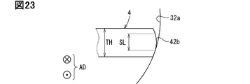
- the tip surface of the tip portion 42b has a curved surface formed with a predetermined radial dimension.
- the shaft 21 rotates around the rotation axis.
- the torque output by the motor unit 2 is transmitted to the pump rotor 106 via the pedestal unit 373 and the drive pin 64.
- the pump rotor 106 rotates in the cylinder 32 with an arcuate seal portion closest to the inner peripheral surface 32a and a separating portion largely separated from the inner peripheral surface 32a of the outer peripheral surface 6c.
- the separating portion is a portion located on the outer peripheral surface 6c on the side opposite to the arc-shaped sealing portion. The length of the portion protruding outward in diameter from the outer peripheral surface 6c is maximum at the separation portion and minimum at the arc-shaped seal portion.
- the vane rotates together with the pump rotor 106 while sliding in the radial direction and sliding on or separating from the inner peripheral surface 32a of the cylinder 32.
- a minute gap is provided in the inner peripheral surface 32a and the tip portion 42b of the cylinder 32 so that the vane does not stretch during one rotation of the vane.
- the minute gap is preferably set to about 50 ⁇ m to 200 ⁇ m in order to suppress leakage of the working fluid and noise.
- the gap between the tip portion 42b and the inner peripheral surface 32a in the arc-shaped seal portion is almost constant, and a stable seal length can be secured in the arc-shaped seal portion.
- the rotation angle of the arc-shaped seal portion is preferably set in the range of 20 degrees to 60 degrees from the viewpoint of suppressing wear of vanes and the like. During one rotation of the vane, the rotation position where the gap between the tip portion 42b and the inner peripheral surface 32a is minimized is displaced. One of the tip portions 42b of the vane may come into contact with the inner peripheral surface 32a at the rotational position excluding the arcuate seal portion and the separating portion.
- the inner peripheral surface 32a of the vane and the cylinder 32 is formed so that the gap between the other tip portion 42b and the inner peripheral surface 32a becomes substantially constant while the vane makes one rotation.
- the fluid machine 101 forms a narrow compression chamber 73 on the arc-shaped seal portion side and a wide compression chamber 73 on the separation portion side.
- the narrow compression chamber 73 moves in the direction of rotation while the vane rotates, and expands as it approaches the separated portion to change into a wide compression chamber 73.
- the wide compression chamber 73 moves in the rotational direction while the vane rotates, and shrinks as it approaches the arcuate seal portion to change into a narrow compression chamber 73. In this way, each compression chamber 73 changes so as to gradually reduce its volume while approaching the discharge chamber introduction passage 74 during one rotation of the vane.
- the fluid machine 101 compresses the air supplied to the compression chamber 73 through the compression chamber introduction passage 72, and discharges this air from the discharge chamber introduction passage 74 to the discharge chamber 75.
- Air which is a working fluid in the fluid machine 101, flows down in the order of the external suction passage 70, the suction chamber 71, the compression chamber introduction passage 72, and the compression chamber 73. Further, the air flows down from the compression chamber 73 in the order of the discharge chamber introduction passage 74 and the discharge chamber 75, and flows out from the discharge port 76 to the outside. In this way, the air cools each part in the process of flowing through this fluid path, and particularly contributes to effectively releasing the heat of the sliding part.
- Each of the first vane 104 and the second vane 5 is a through vane extending through the central axis of the pump rotor 106 and penetrating the pump rotor 106.
- This through vane has a longer support length at a portion supported by the pump rotor 106 than a vane having a shape that does not pass through the central axis of the pump rotor 106. Therefore, the load received from the vane on the portion of the pump rotor 106 in which the slit is formed can be suppressed. According to this effect, the thru-vane type fluid machine 101 can form the pump rotor 106 from the resin. It is preferable to use polyphenylene sulfide or polyether ether ketone as this resin to provide heat resistance.
- the pump rotor 106 may be made of a self-lubricating material containing polytetrafluoroethylene or carbon.
- the through-vane type fluid machine 101 includes a pump rotor 106, a shaft 21 that applies a rotational driving force to the pump rotor 106, and a vane that slides in the radial direction through the central axis of the pump rotor 106.
- the fluid machine 101 includes a compression chamber 73 that compresses the working fluid as the pump rotor rotates, and a support portion that connects the supported portion 61 of the pump rotor 106 and the shaft 21.
- the compression chamber 73 is partitioned in the circumferential direction by vanes between the inner peripheral surface of the housing and the outer peripheral surface 6c of the pump rotor 106.
- the supported portion and the supported portion 61 are integrally connected so as to be relatively axially movable and / or tiltable.
- the pump rotor 106 can move or tilt in the axial direction with respect to the axial direction of the support portion due to the unique connecting structure of the support portion and the supported portion 61. That is, it is possible to reduce the restraint of the pump rotor 106 with respect to the posture of the shaft 21 and the support portion, and increase the degree of freedom regarding the posture of the pump rotor 106. Due to the displaceable characteristics of the pump rotor 106, it is possible to prevent the pump rotor 106 from strongly contacting peripheral members such as the first plate 35 and the second plate 36 and locally receiving a load. Therefore, it is possible to provide a through-vane type fluid machine capable of suppressing machine loss.
- the support portion is provided with a gap portion extending in the radial direction through the central axis of the pump rotor 106 inside the portion in contact with the supported portion 61.
- This gap is formed between the facing surfaces 372a and the facing surfaces 372a that face each other in the pair of other side support portions 1372.
- a sliding extension portion 51 of the second vane 5 is located in this gap. According to this, it is possible to provide a fluid machine having a function of suppressing mechanical loss and sliding a vane inside a support portion.
- the pump rotor 106 is provided with a slit on one side of the supported portion 61 and a slit on the other side of the supported portion 61 in the axial direction.
- the one-side slit extends in the radial direction of the pump rotor 106 through the central axis of the pump rotor 106.
- the other side slit extends axially from both radial ends of the one side slit.
- the pump rotor 106 having a supported portion on the central side in the axial direction. Since the pump rotor 106 can be displaced with respect to the support portion starting from the axial center side, the pump rotor 106 can have a symmetrical movable range starting from the axial center. According to this, it is possible to provide a through-vane type fluid machine capable of evenly suppressing mechanical loss for peripheral members existing on either side in the axial direction with respect to the pump rotor 106.
- the shaft 21 is provided on only one side of the pump rotor 106 in the axial direction and is supported by a bearing portion.
- the shaft 21 has a configuration in which the shaft 21 is not supported by the bearing portion on the other side of the pump rotor 106 in the axial direction. According to this, the shaft 21 is rotatably provided on only one side of the pump rotor 106 and is not provided on the other side. Therefore, since the inclination of the shaft 21 can be suppressed, it is possible to provide the fluid machine 101 that can reduce the inclination range of the pump rotor 106.
- the bearing portions provided on both sides of the motor rotor 22 in the motor portion 2 are bearing portions provided on one side of the pump rotor 106. According to this, it is possible to provide a fluid machine 101 that contributes to suppressing the inclination of the shaft 21 and can reduce the inclination range of the pump rotor 106.
- the fluid machine 101 is a device used under non-lubricating conditions where no lubricating oil is supplied from the outside. According to this, it is possible to provide a fluid machine 101 that can suppress mechanical loss between the pump rotor 106 and surrounding members due to the displaceable characteristics of the pump rotor 106 and also contributes to prevention of seizure when no lubrication is applied.
- the third embodiment will be described with reference to FIGS. 19 to 20.
- the fluid machine 201 of the third embodiment is different from the first embodiment in that it is a rotary vane type fluid machine.
- the configurations, actions, and effects that are not particularly described in the third embodiment are the same as those in the above-described embodiment, and only the differences will be described below.
- the fluid machine 201 is a rotary vane type fluid machine including a cylinder 132 and a pump rotor 206.
- the cylinder 132 is part of the housing in the fluid machine 201.
- a compression chamber 73 is formed between the outer peripheral surface 6c of the pump rotor 206 and the inner peripheral surface 32a of the cylinder 32.
- a vane 204 is slidably mounted on the cylinder 132.
- the vane 204 slides in the radial direction while being fitted in the slit 132s formed in the cylinder 132.
- the tip portion 204a of the vane 204 located on the rotor side is in contact with the outer peripheral surface 6c of the pump rotor 206.
- the other tip portion 204b of the vane 204 is in contact with an elastic member 39 such as a spring.
- an elastic member 39 such as a spring.
- the vane 204 is urged to the pump rotor 206 so that the tip portion 204a is pressed against the outer peripheral surface 6c of the pump rotor 206.
- the tip portion 204a located on the rotor side of the vane 204 slides with respect to the outer peripheral surface 6c of the pump rotor 206 as the pump rotor 206 rotates.
- the fluid machine 201 includes two compression chambers 73 divided in the circumferential direction by the vane 204.
- Each compression chamber 73 is partitioned by a vane 204, an inner peripheral surface 32a of the cylinder 32, an outer peripheral surface 6c of the pump rotor 206, a first plate 35, and a second plate 36.
- An eccentric portion 38 is fixed to the other end shaft portion 21b of the shaft 21.
- the eccentric portion 38 is installed so that the central axis is displaced from the rotation axis of the shaft 21.
- the eccentric portion 38 is fixed to the pump rotor 206 so that the central axis coincides with the central axis of the pump rotor 206. Therefore, the central axis of the pump rotor 206 is set at a position shifted from the central axis of the shaft 21.
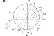
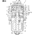
- FIGS. 21 to 23 A fourth embodiment that discloses an example of a fluid machine will be described with reference to FIGS. 21 to 23.
- the fluid machine is a thru-vane type fluid machine.
- the vanes are arranged through the central axis of the pump rotor 106.
- the vane extends through the pump rotor 106.
- the vane is supported by the pump rotor 106 so as to slide in the radial direction of the pump rotor 106.
- the same elements as those shown in FIG. 11 and the corresponding elements are designated by the same reference numerals. With respect to the elements of this embodiment, the description of the preceding embodiment can be referred to.
- FIG. 11 the description of the preceding embodiment can be referred to.
- the external suction passage 70 has a first passage portion 70a and a second passage portion 70b.
- the external suction passage 70 is a columnar shape having no step portion.
- the external suction passage 70 in the embodiment of FIG. 21 may include a first passage portion 70a and a second passage portion 70b.
- the introduction member 8 is provided.
- the embodiment of FIG. 21 does not include an introduction member 8.
- the embodiment of FIG. 21 may include an introduction member 8.
- the suction chamber case 131 forms a suction chamber 71 inside which the working fluid is sucked.
- the suction chamber case 131 is provided with an external suction port 70 for sucking the working fluid flowing out from the external device into the suction chamber 71.
- the external suction port 70 is a passage that penetrates the suction chamber case 131 in the radial direction, and is an inlet portion that takes in the working fluid inside the fluid machine 101.
- the area of the cross section of the external suction port 70 orthogonal to the passage axis direction is set to S0.
- the cross-sectional area of the suction chamber 71 immediately after the working fluid flows into the external suction port 70 is set to S1.
- the cross-sectional area S1 is the cross-sectional area of a plane orthogonal to the radial direction RD.
- This cross section is a cross section at the position where the length of the axial AD is the longest in the suction chamber 71.
- the cross section having S1 and the cross section having an area S0 are planes parallel to each other. It is preferable that S1 is set to a value 10 times or more that of S0.
- the area of the cross section of the suction chamber 71 orthogonal to the axial direction is set to S11.
- the cross-sectional area S11 is the area of the cross section at the largest position in the suction chamber 71.
- the compression chamber introduction passage 72 is elongated in the circumferential direction and forms an opening having a shape along the inner peripheral surface 32a of the cylinder 32.
- the area of the cross section of the compression chamber introduction passage 72 orthogonal to the passage axis direction is set to S2.
- the cross section having the area S11 and the cross section having the area S2 are planes parallel to each other. It is preferable that S11 is set to a value 10 times or more that of S2. Such a magnitude relationship between S0, S1, S11 and S2 contributes to reducing the backflow of radiated sound due to inhalation pulsation.
- the compression chamber introduction passage 72 is located in an area opposite to the suction port area on the side where the external suction port 70 is located with respect to the shaft 21. That is, when viewed in the axial direction of the shaft 21, the compression chamber introduction passage 72 and the external suction port 70 are located in areas facing each other between the shaft 21.
- the discharge chamber introduction passage 74 is elongated in the circumferential direction and forms an opening having a shape along the inner peripheral surface 32a of the cylinder 32.
- the cylinder 32, the pump rotor 106, the first vane 104, and the second vane 5 constitute a compression mechanism for sucking in, compressing, and discharging the working fluid.
- a cylindrical pump rotor 106 is provided inside the cylindrical cylinder 32.
- the second vane 5 and the first vane 104 are slidably mounted on the pump rotor 106 in a posture orthogonal to each other.
- Each of the first vane 104 and the second vane 5 slides in the radial direction while being fitted in the slit formed in the pump rotor 106.
- the tip portion 42b on the outer diameter of the first vane 104 slides with respect to the inner peripheral surface 32a of the cylinder 32 as the pump rotor 106 rotates.
- the tip portion 52b on the outer diameter of the second vane 5 slides with respect to the inner peripheral surface 32a of the cylinder 32 as the pump rotor 106 rotates.
- Each of the plurality of compression chambers 73 is formed between the second vane 5 and the first vane 104 adjacent to each other in the circumferential direction.
- the compression chamber 73 is partitioned by a second vane 5, a first vane 104, an inner peripheral surface 32a of the cylinder 32, an outer peripheral surface 6c of the pump rotor 106, a first plate 35, and a second plate 36.
- the fluid machine 101 has four compression chambers 73 arranged in the circumferential direction.
- the fluid machine 1 has two narrow compression chambers 73 and two wide compression chambers 73 located on opposite sides of the two narrow compression chambers 73.
- the four compression chambers 73 move in the circumferential direction as the pump rotor 106 rotates.
- the pump rotor side end surface 212a and the motor side end surface 212b are located at positions facing each other in the axial direction of the shaft 21, and each forms an annular surface around the axis of the shaft 21.
- the pump rotor end face 212a is exposed to the suction chamber 71 and may come into contact with the working fluid flowing through the suction chamber 71.
- the motor side end surface 212b is not exposed to the suction chamber 71 and does not come into contact with the working fluid.
- FIG. 22 shows the positional relationship between the inner peripheral surface 32a of the cylinder 32 and the tip portion 42b on the outer diameter of the first vane 4 at the rotational position of the pump rotor 6.
- the following description applies to each of the first vane 4 and the second vane 5.
- the tip surface of the tip portion 42b has a curved surface formed with a predetermined radial dimension.
- the pump rotor 6 rotates in the cylinder 32 with an arcuate seal portion closest to the inner peripheral surface 32a and a separating portion largely separated from the inner peripheral surface 32a of the outer peripheral surface 6c.
- the arc-shaped seal portion corresponds to the range of the rotation angle AG.
- the separating portion is a portion located on the outer peripheral surface 6c on the side opposite to the arc-shaped sealing portion. The length of the portion protruding outward in diameter from the outer peripheral surface 6c is maximum at the separation portion and minimum at the arc-shaped seal portion.
- the vane rotates together with the pump rotor 6 while sliding in the radial direction and sliding on or separating from the inner peripheral surface 32a of the cylinder 32.
- the tip portion 42b of the first vane 4 is displaced, for example, as shown by the alternate long and short dash line in FIG.
- a minute gap is provided in the inner peripheral surface 32a and the tip portion 42b of the cylinder 32 so that the vane does not stretch during one rotation of the vane.
- the minute gap is preferably set to about 50 ⁇ m to 200 ⁇ m in order to suppress leakage of the working fluid and noise.
- the gap GP1 between the tip portion 42b and the inner peripheral surface 32a in the arc-shaped seal portion is substantially constant, and a stable seal length can be secured in the arc-shaped seal portion.
- the rotation angle AG of the arc-shaped seal portion is preferably set in the range of 20 degrees to 60 degrees from the viewpoint of suppressing wear of vanes and the like.
- the rotation position where the gap between the tip portion 42b and the inner peripheral surface 32a is minimized is displaced.
- One of the tip portions 42b of the vane may come into contact with the inner peripheral surface 32a at the rotational position excluding the arcuate seal portion and the separating portion.
- the other tip portion 42b and the inner peripheral surface 32a are set to the gap GP2.
- the inner peripheral surface 32a of the vane and the cylinder 32 is formed so that the gap GP2 becomes substantially constant while the vane makes one rotation.
- the tip surface of the tip portion 42b is formed in a curved shape so that the sliding length SL that slides in contact with the inner peripheral surface 32a is smaller than the vane thickness TH. With this configuration, a stable sliding state of the vane can be ensured.
- a fifth embodiment will be described with reference to FIGS. 24 to 28.
- the fluid machine 501 of the fifth embodiment is different from the embodiments of FIGS. 11 and 21 in that it has two compression chambers 73 partitioned by vanes.
- the configurations, actions, and effects that are not particularly described in the fifth embodiment are the same as those in the above-described embodiment, and only the differences will be described below.
- the fluid machine 501 of FIG. 24 includes only one through vane. Due to this configuration, the fluid machine 501 of FIG. 24 differs from the fluid machine 101 of FIG. 21 in the connecting portion 537 and the pump rotor 506.
- the configuration of the pump rotor 506 will be described with reference to FIGS. 25, 26, 27, and 28.
- the pump rotor 506 includes a supported portion 61 that is in contact with and supported by the connecting portion 537.
- the connecting portion 537 is a member that connects the pump rotor 506 and the shaft 21.
- the connecting portion 537 is not press-fitted into the inner peripheral surface of the supported portion 61 but is partially in contact with the connecting portion 537, and the connecting portion 537 and the supported portion 61 are fitted to each other.
- the pump rotor 506 includes a one-sided cylindrical portion 62 located closer to the motor portion 2 than the supported portion 61, and a other-side tubular portion 63 located closer to the discharge chamber 75 than the supported portion 61. ..
- the pump rotor 506 has a penetrating portion that is axially penetrated by a one-sided cylindrical portion 62, a supported portion 61, and the other-side tubular portion 63.
- the pump rotor 506 is provided with a first slit 6sa1 and a second slit 6sa2 similar to the pump rotor 106.
- the first slit 6sa1 in the pump rotor 506 is a one-side slit extending in the radial direction through the central axis of the pump rotor 506 on one side of the supported portion 61 in the axial direction.
- the second slit 6sa2 in the pump rotor 506 is the other side slit extending axially from both radial ends of the one side slit on the other side of the supported portion 61.
- the pump rotor 506 is not provided with the third slit 6sb1 and the fourth slit 6sb2 provided in the pump rotor 106.
- the fluid machine 501 has a first vane 4 fitted in the first slit 6sa1 and the second slit 6sa2.
- the first slit 6sa1 and the second slit 6sa2 are continuous, and a convex U-shaped slit is formed on the discharge chamber 75 side.
- the connecting part 537 and the pump rotor 506 are separate parts.
- the connecting portion 537, the pump rotor 506, and the shaft 21 are arranged coaxially and are rotationally driven integrally.
- the other end shaft portion 21b of the shaft 21 is coupled to the connecting portion 537.
- the connecting portion 537 includes a one-sided coupling portion 371 that couples to the shaft 21 and a other-side support portion 1372 that supports the pump rotor 506.
- the one-side coupling portion 371 is located on the motor portion 2 side in the connecting portion 537.
- the other side support portion 1372 is located on the discharge chamber 75 side in the connecting portion 537.
- the other side support portion 1372 is a columnar portion formed coaxially with the shaft 21.
- the pump rotor 506 is in contact with the outer peripheral surface of the other side support portion 1372 in the supported portion 61, and is not in contact with the connecting portion 537 in the portion other than the supported portion 61.
- the other side support portion 1372 supports the supported portion 61 so that the pump rotor 506 and the connecting portion 537 can move relatively in the axial direction. Further, the other side support portion 1372 supports the supported portion 61 so that the connecting portion 537 and the pump rotor 506 can tilt relative to the axial center of the shaft 21.
- Each of the two compression chambers 73 is partitioned by a first vane 4, an inner peripheral surface 32a of the cylinder 32, an outer peripheral surface 6c of the pump rotor 506, a first plate 35, and a second plate 36.
- the fluid machine 501 has two compression chambers 73 arranged in the circumferential direction with the first vane 4 as a boundary. The two compression chambers 73 move in the circumferential direction as the pump rotor 506 rotates.
- the fluid machine 501 forms a narrow compression chamber 73 at a position including the arcuate seal portion and a wide compression chamber 73 at a position including the separation portion while the vane makes one rotation.
- the narrow compression chamber 73 moves in the rotation direction with the rotation of the first vane 4, and changes to a wide compression chamber 73 when it reaches a rotation position including a separation portion.
- the wider compression chamber 73 moves in the rotational direction with the rotation of the first vane 4, and changes to a narrow compression chamber 73 when it reaches the rotation position including the arcuate seal portion.
- the volume of each compression chamber 73 gradually decreases as the tip portion 42b approaches the discharge chamber introduction passage 74 while the first vane 4 makes one rotation. Therefore, the air supplied to the compression chamber 73 through the compression chamber introduction passage 72 is compressed, and this air is discharged from the discharge chamber introduction passage 74 to the discharge chamber 75.
- the pump rotor 506 of the fifth embodiment is provided with a slit on one side of the supported portion 61 and a slit on the other side of the supported portion 61 in the axial direction.
- the one-side slit extends in the radial direction of the pump rotor 506 through the central axis of the pump rotor 506.
- the other side slit of the pump rotor 506 extends axially from both radial ends of the one side slit.
- This embodiment is a modification based on a preceding embodiment or a modification as a basic embodiment.
- the fluid machine 1 includes a second seal portion 618.
- the second seal portion 618 is in contact with the shaft 21 and the first plate 35, and fluidly seals the gap between them.
- the second seal portion 618 blocks the fluid communication state between the space on the pump side and the space on the suction chamber 71 side.
- the second seal portion 618 is in contact with the shaft 21.
- the second seal portion 18 is in contact with the outer peripheral surface of the shaft 21.
- the contact portion of the shaft 21 with the second seal portion 618 is included in the drive shaft portion for driving the pump rotor 6.
- the shaft 21 is arranged so as to penetrate the first plate 35. In other words, the drive shaft portion is arranged so as to penetrate the first plate 35.
- the second seal portion 618 is held between the first plate 35, which is a member through which the drive shaft portion penetrates, and the end face on the compression chamber side of the cylindrical wall portion 341.
- the second seal portion 618 is sandwiched between the first plate 35 and the cylindrical wall portion 341.
- An elastic member such as an O-ring is arranged between the end surface of the tubular wall portion 341 on the compression chamber side and the second seal portion 618.
- the second seal portion 618 is pressed against the first plate 35 by the O-ring.
- the second seal portion 618 provides a lip seal that allows the shaft 21 to rotate.
- the second seal portion 618 is held so as to allow the shaft 21 to rotate.
- the second seal portion 618 suppresses fluid flow and leakage through the gap between the first plate 35 and the shaft 21.
- the second seal portion 618 suppresses the leakage of fluid from the compression chamber 73 side to the suction chamber 71 side.
- the central axis of the shaft 21 is the rotation axis of the pump rotor 6.
- the shaft 21 includes a drive pin 664.
- the shaft 21 is a portion that rotates the pump rotor 6 via the drive pin 664.
- the shaft 21 constitutes a drive shaft portion that drives the pump rotor 6 together with the connecting portion 37.
- the drive pin 664 is connected to the shaft 21 so as to rotate with the shaft 21.
- the drive pin 664 is connected by fitting the annular base and the shaft 21.
- the shaft 21 may be press-fitted into the annular base.
- the shaft 21 and the drive pin 664 provide a drive shaft portion for rotationally driving the pump rotor 6.
- the shaft 21 and the pump rotor 6 are provided with a support portion 372 that supports the pump rotor 6.
- the drive pin 664 connects the shaft 21 and the pump rotor 6 in the rotational direction on the radial outer side of the support portion 372.
- the connection between the drive pin 664 and the pump rotor 6 may be provided by a slightly looser fit than at the support 372 in the axial and radial directions.
- the suction chamber case 31 as a housing includes a communication passage 340 that communicates the suction chamber 71 and the end face 212a on the pump rotor side.
- the communication passage 340 may include a groove-shaped passage on the end surface of the tubular wall portion 341 on the compression chamber side.
- the communication passage 340 may include a passage that axially penetrates the wall providing the compression chamber side end surface of the tubular wall portion 341.
- the communication passage 340 is formed between the second seal portion 618 and the tubular wall portion 341.
- the suction chamber case 31 as a housing includes a communication passage 631.
- the communication passage 631 directly or indirectly fluidly communicates the suction chamber 71 and the motor chamber 241.
- the communication passage 340 and the communication passage 631 that directly or indirectly expose both the pump rotor side end surface 212a and the motor side end surface 212b of the second bearing portion 212 to the suction chamber 71. It has both.
- the communication passage 631 is formed on the partition wall of the suction chamber case 31 that partitions the suction chamber 71 and the motor chamber 241.
- the passage 631 is provided by a hole drilled in the compartment wall.
- the filter 15 is arranged so as to filter the fluid between the external suction passage 70 and the communication passage 340.
- the filter 15 is arranged so as to filter the fluid between the external suction passage 70 and the communication passage 631.
- the filter 15 suppresses the intrusion of foreign matter from the outside into both the pump rotor side end surface 212a and the motor side end surface 212b of the second bearing portion 212.
- the communication passage 340 and the communication passage 631 suppress the differential pressure between the pump rotor side end surface 212a and the motor side end surface 212b of the second bearing portion 212 even if the suction chamber 71 becomes a negative pressure due to the suction loss. Will be done. As a result, the outflow of grease from the second bearing portion 212 can be suppressed.
- This embodiment is a modification based on a preceding embodiment or a modification as a basic embodiment.
- the filter 15 is arranged so as to partition the suction chamber 71 into two chambers.
- the two chambers are positioned so as to be stacked in the axial direction.
- the filter 15 is arranged in the suction chamber case 31.
- the filter 15 may have a shape corresponding to the shape of the opening of the suction chamber case 31.
- the suction chamber case 31 includes a step portion for arranging the filter 15.
- the filter 15 is fixed to the suction chamber case 31.
- the filter 15 is fixed to the suction chamber case 31 by an adhesive or a mechanical fastening member.
- the filter 15 is arranged so as to be placed in the suction chamber case 31 according to gravity through the opening of the suction chamber case 31.
- the filter 15 is fixed after being placed inside the suction chamber case 31.
- the process of assembling the filter 15 in the method for manufacturing a fluid machine can be simplified.
- the filter 15 is arranged so as to filter the fluid between the external suction passage 70 and the compression chamber introduction passage 72. As a result, the filter 15 suppresses the intrusion of foreign matter into the pump from the outside. Further, the filter 15 is arranged so as to filter the fluid between the external suction passage 70 and the pump rotor side end surface 212a of the second bearing portion 212. As a result, the filter 15 suppresses the intrusion of foreign matter from the outside into the pump rotor side end surface 212a of the second bearing portion 212.
- This embodiment also produces the effects provided by the elements common to the preceding embodiments.
- This embodiment is a modification based on a preceding embodiment or a modification as a basic embodiment.
- This embodiment shows an example of a structure for fixing the filter 15.
- the fluid machine 1 of this embodiment includes a spacer member 831 for fixing the filter 15.
- the spacer member 831 is arranged in the suction chamber case 31 to limit the movement of the filter 15.
- the filter 15 is held between the spacer member 831 and the suction chamber case 31.
- the filter 15 can be held between the member that partitions the suction chamber 71 and the spacer member 831.
- the filter 15 may be held between the spacer member 831 and the first plate 35.
- the spacer member 831 allows the fluid to flow in the axial direction. Further, the spacer member 831 allows the fluid that has passed through the filter 15 to reach the end surface 212a on the pump rotor side of the second bearing portion 212.
- the spacer member 831 can be provided by a member that transmits fluid in the radial direction or a member that has a fluid passage in the radial direction. This embodiment also produces the effects provided by the elements common to the preceding embodiments.
- Disclosure of this specification is not limited to the illustrated embodiments.
- the disclosure includes exemplary embodiments and modifications by those skilled in the art based on them.
- the disclosure is not limited to the combination of parts and elements shown in the embodiment, and can be implemented in various modifications. Disclosure can be carried out in various combinations.
- the disclosure can have additional parts that can be added to the embodiment.
- the disclosure includes parts and elements of the embodiment omitted. Disclosures include replacements or combinations of parts, elements between one embodiment and another.
- the technical scope disclosed is not limited to the description of the embodiments.
- the disclosed technical scope is indicated by the description of the claims and should be understood to include all modifications within the meaning and scope equivalent to the description of the claims.
- the fluid machine capable of achieving the object disclosed in this specification shall include a form in which at least two or more of the first to fifth modifications of the fluid machine 1 are combined.
- the support portion and the supported portion which are separate parts, are integrally connected, but the support portion and the shaft may be separate parts or one part.
- the connecting portion having the support portion in the above-described embodiment is a separate component with respect to the shaft, the connecting portion and the shaft may be configured as one component.
- the supported portion 61 of the pump rotor is provided in the middle of the pump rotor in the axial direction, but the configuration is not limited to this.
- the supported portion 61 may be provided on the motor portion 2 side in the axial direction of the pump rotor.
- the supported portion 61 may be provided on the discharge chamber 75 side in the axial direction of the pump rotor.
Landscapes
- Engineering & Computer Science (AREA)
- Mechanical Engineering (AREA)
- General Engineering & Computer Science (AREA)
- Applications Or Details Of Rotary Compressors (AREA)
- Rotary Pumps (AREA)
Priority Applications (1)
| Application Number | Priority Date | Filing Date | Title |
|---|---|---|---|
| JP2022575158A JP7485093B2 (ja) | 2021-01-14 | 2021-12-17 | 流体機械 |
Applications Claiming Priority (2)
| Application Number | Priority Date | Filing Date | Title |
|---|---|---|---|
| JP2021-004504 | 2021-01-14 | ||
| JP2021004504 | 2021-01-14 |
Publications (1)
| Publication Number | Publication Date |
|---|---|
| WO2022153786A1 true WO2022153786A1 (ja) | 2022-07-21 |
Family
ID=82447226
Family Applications (1)
| Application Number | Title | Priority Date | Filing Date |
|---|---|---|---|
| PCT/JP2021/046688 Ceased WO2022153786A1 (ja) | 2021-01-14 | 2021-12-17 | 流体機械 |
Country Status (2)
| Country | Link |
|---|---|
| JP (1) | JP7485093B2 (https=) |
| WO (1) | WO2022153786A1 (https=) |
Citations (10)
| Publication number | Priority date | Publication date | Assignee | Title |
|---|---|---|---|---|
| JPS5259310A (en) * | 1975-11-11 | 1977-05-16 | Matsushita Electric Ind Co Ltd | Open type rotary compressor |
| JPS57110790A (en) * | 1980-12-29 | 1982-07-09 | Toyoda Autom Loom Works Ltd | Vane compressor |
| US4484863A (en) * | 1981-10-05 | 1984-11-27 | Hydraulic Services Inc. | Rotary vane pump with undervane pumping and an auxiliary outlet |
| JPS59190986U (ja) * | 1983-06-06 | 1984-12-18 | 三菱電機株式会社 | ベ−ン型ポンプ装置 |
| JPH0218681U (https=) * | 1988-07-19 | 1990-02-07 | ||
| JPH05113184A (ja) * | 1991-10-22 | 1993-05-07 | Daikin Ind Ltd | スクリユー圧縮機 |
| JPH0680890U (ja) * | 1993-04-15 | 1994-11-15 | 株式会社ゼクセル | ベーン型圧縮機 |
| JP2006177232A (ja) * | 2004-12-22 | 2006-07-06 | Matsushita Electric Ind Co Ltd | ベーンロータリ型空気ポンプ |
| JP2014077411A (ja) * | 2012-10-11 | 2014-05-01 | Nissin Kogyo Co Ltd | ベーンポンプ |
| JP2020122424A (ja) * | 2019-01-30 | 2020-08-13 | 株式会社豊田自動織機 | 容積形圧縮機 |
-
2021
- 2021-12-17 JP JP2022575158A patent/JP7485093B2/ja active Active
- 2021-12-17 WO PCT/JP2021/046688 patent/WO2022153786A1/ja not_active Ceased
Patent Citations (10)
| Publication number | Priority date | Publication date | Assignee | Title |
|---|---|---|---|---|
| JPS5259310A (en) * | 1975-11-11 | 1977-05-16 | Matsushita Electric Ind Co Ltd | Open type rotary compressor |
| JPS57110790A (en) * | 1980-12-29 | 1982-07-09 | Toyoda Autom Loom Works Ltd | Vane compressor |
| US4484863A (en) * | 1981-10-05 | 1984-11-27 | Hydraulic Services Inc. | Rotary vane pump with undervane pumping and an auxiliary outlet |
| JPS59190986U (ja) * | 1983-06-06 | 1984-12-18 | 三菱電機株式会社 | ベ−ン型ポンプ装置 |
| JPH0218681U (https=) * | 1988-07-19 | 1990-02-07 | ||
| JPH05113184A (ja) * | 1991-10-22 | 1993-05-07 | Daikin Ind Ltd | スクリユー圧縮機 |
| JPH0680890U (ja) * | 1993-04-15 | 1994-11-15 | 株式会社ゼクセル | ベーン型圧縮機 |
| JP2006177232A (ja) * | 2004-12-22 | 2006-07-06 | Matsushita Electric Ind Co Ltd | ベーンロータリ型空気ポンプ |
| JP2014077411A (ja) * | 2012-10-11 | 2014-05-01 | Nissin Kogyo Co Ltd | ベーンポンプ |
| JP2020122424A (ja) * | 2019-01-30 | 2020-08-13 | 株式会社豊田自動織機 | 容積形圧縮機 |
Also Published As
| Publication number | Publication date |
|---|---|
| JPWO2022153786A1 (https=) | 2022-07-21 |
| JP7485093B2 (ja) | 2024-05-16 |
Similar Documents
| Publication | Publication Date | Title |
|---|---|---|
| US6196814B1 (en) | Positive displacement pump rotatable in opposite directions | |
| JP2005054803A (ja) | 小型回転圧縮機 | |
| KR20120006015A (ko) | 칸투어드 체크밸브 디스크 및 이를 갖는 스크롤 압축기 | |
| CN111684159B (zh) | 双旋转涡旋型压缩机及其组装方法 | |
| JP4104047B2 (ja) | スクロール圧縮機 | |
| WO2024130821A1 (zh) | 一种具有循环润滑油路结构的涡旋式压缩机 | |
| CN110382868B (zh) | 具有轴向通量马达的涡旋式压缩机 | |
| JP6330243B2 (ja) | スクロールポンプ | |
| WO2022153786A1 (ja) | 流体機械 | |
| JP6633305B2 (ja) | スクロール圧縮機 | |
| CN112879303A (zh) | 涡旋压缩机 | |
| CN102597525A (zh) | 旋转式压缩机 | |
| JP5865960B2 (ja) | 圧縮機 | |
| JP7524837B2 (ja) | 流体機械 | |
| JP4277995B2 (ja) | 電動圧縮機及びその製造方法 | |
| WO2009090888A1 (ja) | 回転式流体機械 | |
| JP2002122088A (ja) | 真空ポンプにおける流路構造 | |
| JPH0357893A (ja) | スクロール流体機械 | |
| JP7165549B2 (ja) | スクロール圧縮機 | |
| JP2012013029A (ja) | 圧縮機 | |
| CN113286946A (zh) | 涡旋式压缩机 | |
| KR102809392B1 (ko) | 전동식 컴프레서 장치 | |
| CN110005613B (zh) | 一种压缩机 | |
| JP2025523234A (ja) | スクロールポンプシール、スクロールポンプ及び方法 | |
| JP7126421B2 (ja) | スクロール圧縮機 |
Legal Events
| Date | Code | Title | Description |
|---|---|---|---|
| 121 | Ep: the epo has been informed by wipo that ep was designated in this application |
Ref document number: 21919674 Country of ref document: EP Kind code of ref document: A1 |
|
| ENP | Entry into the national phase |
Ref document number: 2022575158 Country of ref document: JP Kind code of ref document: A |
|
| NENP | Non-entry into the national phase |
Ref country code: DE |
|
| 122 | Ep: pct application non-entry in european phase |
Ref document number: 21919674 Country of ref document: EP Kind code of ref document: A1 |