WO2022145116A1 - 奏鳴玩具 - Google Patents
奏鳴玩具 Download PDFInfo
- Publication number
- WO2022145116A1 WO2022145116A1 PCT/JP2021/038849 JP2021038849W WO2022145116A1 WO 2022145116 A1 WO2022145116 A1 WO 2022145116A1 JP 2021038849 W JP2021038849 W JP 2021038849W WO 2022145116 A1 WO2022145116 A1 WO 2022145116A1
- Authority
- WO
- WIPO (PCT)
- Prior art keywords
- opening
- sounding
- unit
- doll
- speaker
- Prior art date
- Legal status (The legal status is an assumption and is not a legal conclusion. Google has not performed a legal analysis and makes no representation as to the accuracy of the status listed.)
- Ceased
Links
Images





Classifications
-
- A—HUMAN NECESSITIES
- A63—SPORTS; GAMES; AMUSEMENTS
- A63B—APPARATUS FOR PHYSICAL TRAINING, GYMNASTICS, SWIMMING, CLIMBING, OR FENCING; BALL GAMES; TRAINING EQUIPMENT
- A63B43/00—Balls with special arrangements
-
- A—HUMAN NECESSITIES
- A63—SPORTS; GAMES; AMUSEMENTS
- A63H—TOYS, e.g. TOPS, DOLLS, HOOPS OR BUILDING BLOCKS
- A63H3/00—Dolls
- A63H3/28—Arrangements of sound-producing means in dolls; Means in dolls for producing sounds
-
- A—HUMAN NECESSITIES
- A63—SPORTS; GAMES; AMUSEMENTS
- A63H—TOYS, e.g. TOPS, DOLLS, HOOPS OR BUILDING BLOCKS
- A63H5/00—Musical or noise- producing devices for additional toy effects other than acoustical
-
- G—PHYSICS
- G10—MUSICAL INSTRUMENTS; ACOUSTICS
- G10K—SOUND-PRODUCING DEVICES; METHODS OR DEVICES FOR PROTECTING AGAINST, OR FOR DAMPING, NOISE OR OTHER ACOUSTIC WAVES IN GENERAL; ACOUSTICS NOT OTHERWISE PROVIDED FOR
- G10K15/00—Acoustics not otherwise provided for
- G10K15/04—Sound-producing devices
Definitions
- the present invention relates to a playing toy configured so that the pitch can be changed depending on the posture.
- Japanese Patent Application Laid-Open No. 2008-183393 and Japanese Patent No. 5866665 are whistle toys according to the invention of the present inventor.
- Japanese Patent Application Laid-Open No. 2008-183393 covers the sounding port of a whistle blown by a person with an opening / closing portion, and the opening / closing portion is operated by a person to open / close to adjust the pitch.
- a reciprocating body having a whistle portion is housed in a cylinder portion so that the reciprocating body can reciprocate, and the cylinder portion is inside the opening provided in the hollow body, and the air flowing through the opening portion.
- the whistle portion is attached so that the whistle portion can be reverberated in the cylinder portion by the flow.
- Patent 586,665 when the hollow body is shaken mainly in the direction in which the whistle part reciprocates, the whistle part moves in the cylinder part and the reverberation space in the cylinder part becomes larger or smaller, so that the performance changes. There is a noise. This is because the reverberation space in the cylinder portion increases or decreases according to the reciprocating movement of the reciprocating moving body, but the reciprocating moving body is provided with a whistle portion, and the sound generated from this whistle portion passes through the reverberation space.
- the hollow body is a doll
- the tongue-shaped body is provided with an opening for the tongue at the portion corresponding to the mouth of the doll
- the reciprocating moving body is provided with a tongue-shaped body.
- the tongue-shaped body also moves outward from the tongue opening of the doll, that is, the hollow body, and conversely, the tongue-shaped body also moves inward from the tongue opening. You can enjoy this kind of movement with the sound of the flute. It is also possible to design the opening for the tongue and the opening in common.
- the sounding toy of the present invention is provided with a sounding port provided with a speaker in a hollow body, the speaker is connected to the output end of the oscillating unit, and the oscillating unit is connected to the hollow body. It is assumed that it has a pitch adjustment unit that changes the oscillation frequency by changing the angle of.
- the hollow body may be like a ball, or may be like a stuffed animal or a doll that imitates the shape of a person or an animal.
- the pitch adjustment unit senses this, and as a result, the oscillation unit changes the oscillation frequency, so that the speaker at the sound port of the hollow body emits sound of a different frequency. Will be possible. It is preferable that the on / off switch for operating the oscillating unit is provided at a position where the toy is gripped. Generating electronic sounds (including volume and timbre) and changing the pitch are common techniques, but in developing the mechanical parts that change the pitch, as a hollow toy or doll. It is necessary to consider that it is a hollow body.
- the oscillation frequency can be changed by turning the toy's posture upward or downward, right or left.
- an accelerometer for example, an accelerometer, a gyro sensor, a geomagnetic sensor, or the like can be used.
- the oscillation frequency can be changed by configuring the RLC circuit so that the resistance value, capacitance, and inductance can be changed.
- Such an operation can be performed with only one hand.
- the hollow body is a doll, the sounding mouth is provided at the mouth of the doll, and a person's hand is inserted inside the doll to adjust the opening angle of the mouth.
- An adjustable insertion port is provided, and the pitch adjusting portion slides on a contact piece provided on a pendulum with a weight that is oscillated by a change in the vertical angle of the hollow body. It has a variable resistor composed of a resistor, and the oscillation frequency is changed so that the treble is higher in the upward direction. In the present invention, it is free to change the angle of holding the hollow body in any direction, but preferably, when the angle is changed in the vertical direction, the oscillation frequency is changed so that the treble is higher in the upward direction. This makes it possible to faithfully imitate the movement of the head when a person sings a song.
- a pitch adjusting unit for this purpose, it has a variable resistor composed of a contact piece provided on a pendulum with a weight that is swung by a change in the vertical angle of the hollow body and a resistor on which the contact piece slides. Therefore, the oscillation frequency is changed so that the pitch becomes higher in the upward direction. It is like a wall clock with a variable resistor attached to the rotating shaft of the pendulum. Since the pendulum always tries to maintain a vertical posture due to the action of the weight, the value of the variable resistor changes as the rotation shaft side rotates. It should be noted that a part of the pendulum can be taken out of the body of the doll and can swing freely.
- the pendulum since the part outside the body is also a pendulum, the pendulum having a weight rotates depending on the difference in the vertical angle of holding the doll, and the value of the variable resistor changes. As long as a part of the pendulum is out of the body, it happens that you try to manipulate it by hand, and you can change the oscillation frequency by that, but if you release your hand, the weight will be restored. Only the change in the oscillation frequency due to the action of. Further, the oscillating unit may have a volume adjusting unit that changes the volume by changing the angle of the opening of the mouth portion.
- this playing toy may be provided with a sound source reproduction unit.
- the playback unit reproduces the music converted into digital data and outputs it from the speaker. Not only was the above-mentioned electronic sound played by changing the pitch, but the performance of the song was made to be heard separately by the sound source.
- the song may include a song.
- This sound source may be one recorded in a storage device in a toy, or one recorded in a storage device on the Internet and obtained by downloading or streaming.
- the speaker that outputs the oscillation unit is used as the output destination of the sound source playback unit, but a dedicated speaker is provided separately to output to this dedicated speaker. It is also possible to configure. According to this configuration, the following ways of playing are possible. That is, the sound control unit sends the music obtained from the sound source to the speaker via the reproduction unit. At the same time, the sound control unit plays the above-mentioned electronic sound by changing the pitch. At this time, the pitch change of the electronic sound is made by the posture change of the toy performed by the user.
- the doll which is a toy, play the music of the karaoke sound source, so that the user can turn the doll up to raise the pitch of the electronic sound, and conversely, turn the doll down to make it electronic. If the pitch of the sound is set low, the doll can be played as if it were singing to the song. When you actually operate it in this way, you can see that a sense of unity is created between the user and the doll. Therefore, it is a feature unique to the invention of this claim that not only the user can enjoy it individually, but also the family and the group can compete with each other.
- the sounding toy of the present invention has a cylinder portion attached to the inside of an opening provided in the hollow body, and a sounding port provided with a speaker is provided in the cylinder portion. Is connected to the output end of the oscillating unit, and this oscillating unit has a pitch adjusting unit that changes the oscillation frequency by changing the angle of the hollow body. It is generally similar to the first solution described above, except that the second solution has a cylinder. In the first solution, the output from the oscillating unit is configured to be emitted directly to the outside of the hollow body from the sounding port of the hollow body.
- the output from the oscillating unit is once emitted from the sounding port of the tubular portion into the tubular portion, and then emitted from the opening of the hollow body through the tubular portion to the outside of the hollow body. It is configured.
- This is a configuration in which the tube portion is used as a reverberation space so that richer vocalization can be performed.
- the reciprocating toy is housed in the cylinder so that the reciprocating body can reciprocate, and the reciprocating body moves in the cylinder due to the air flow flowing through the opening. As a result, the volume inside the cylinder is changed to generate a reverberation.
- the second solution may be provided with a sound source reproduction unit. Not only can the above-mentioned electronic sound be played by changing the pitch (although it can be used in combination with another playback device such as live music or music from TV or karaoke), but also the playback unit is separate from this. The performance of the song is made to be heard by the reproduction of the sound source by.
- the electronic sound as the output part of the song from the sound source to a speaker that plays by changing the pitch, but this is not good because the sound of this speaker is related to the container reverberation. If so, it is better to provide another speaker and use this as the output part of the music from the sound source.
- the reciprocating moving body is housed inside the tubular portion via an elastic body.
- the reciprocating body that controls the reverberation reciprocates in the cylinder portion due to the elastic body and the weight of the reciprocating body itself, and causes a slightly different change in the reverberation space depending on the posture of the reciprocating body regardless of the posture of the reciprocating body.
- the elastic body may be any configuration such as a leaf spring, a rubber string, or a magnet that utilizes a repulsive force
- the hollow body may be a ball having elasticity or a concrete body such as a doll or an animal. According to this, the sense of unity between the user and the toy can be further strengthened.
- the tongue opening is provided at the part that hits the mouth of the doll, and the reciprocating body is equipped with a tongue-shaped body. It may be provided so as to reciprocate in the vicinity of the portion.
- the air inside the hollow body moves the reciprocating moving body in the cylinder portion inside the opening and flows out of the hollow body through the opening.
- the air outside the hollow body flows from the opening into the hollow body to move the reciprocating moving body. Since this also appears as the reciprocating motion of the reciprocating moving body, it further appears as the reciprocating motion of the tongue-shaped body provided on the reciprocating moving body. Therefore, when the doll is compressed by hand, the tongue-shaped body moves outward from the doll, that is, the opening for the tongue of the hollow body, and if the hollow body is elastic, the tongue-shaped body is relaxed by loosening the force of the hand. The body moves inward through the tongue opening. You can enjoy the state of such an operation together with the reciprocating moving body that reverberates the above-mentioned electronic sound while changing the pitch. It is also possible to design the opening for the tongue and the opening in common.
- FIG. 1 is an explanatory diagram schematically showing Example 1 in a side view.
- FIG. 2 is an explanatory diagram of the pronunciation control unit 5.
- FIG. 3 is an explanatory diagram schematically showing the pitch adjusting unit 4.
- FIG. 4 is an explanatory diagram of the pronunciation control unit 55 of the second embodiment.
- FIG. 5 is an explanatory diagram schematically showing the pitch adjusting unit 49 of the third embodiment.
- FIG. 6 is an explanatory diagram of the sound control unit 501.
- FIG. 7 is an explanatory diagram schematically showing Example 4 in a side view.
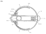
- FIG. 8 is an explanatory diagram schematically showing Example 4 in a bottom view.
- FIG. 9 is an explanatory diagram schematically showing the pitch adjusting unit 45.
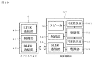
- FIG. 10 is an explanatory diagram of communication between the sound control unit 57 and the smartphone 6.
- FIG. 11 is an explanatory diagram schematically showing Example 5 in a side view.
- FIG. 12 is an explanatory diagram schematically showing the pitch adjusting unit 46
- the puppet 1 sewn as a puppet has an opening 10 on the front side and a hand insertion slot 11 on the rear side.
- the opening 10 is for making the mouth look crisp by hand, and is provided inside with a mouth member configured so that the upper jaw plate 2 and the lower jaw plate 20 can be opened and closed by the rotation shaft 21.
- the rotation shaft 21 incorporates a coil spring (not shown) for urging the upper jaw plate 2 and the lower jaw plate 20 in a direction that always opens.
- a cushion 12 as a padding is packed so that the hand is stable when a hand is inserted from the insertion port 11 and the upper jaw plate 2 and the lower jaw plate 20 are held so as to be sandwiched between fingers. There is.
- a pitch adjusting unit 4 described later is housed in the cushion 12, and is connected to a sounding control unit 5 described later by a lead wire 44.
- a sound control unit 5 and a speaker 3 are attached to the upper jaw plate 2 so that sound can be electronically produced from the opening 10.
- Reference numeral 54 is a slide switch for turning on / off the power of the sounding control unit 5, and the on / off operation can be performed with the finger of the hand inserted from the insertion port 11. When the slide switch 54 is in the ON state, an electronic sound is emitted from the oscillation unit 52 and output from the speaker 3. As shown in FIG.
- the sound generation control unit 5 includes a music storage unit 51 for recording a digital sound source, a speaker 3 for reproducing the digital sound source, an electronic sound oscillation unit 52, and the oscillation unit 52. It is composed of a slide switch 54 for turning on and off, a variable resistance plate 43 for changing the pitch of the oscillation unit 52, a power supply unit 53, and a control unit 50 for controlling these units. That is, the control unit 50 also plays the role of a music reproduction device for a digital sound source. If it is desired to make the sound from the speaker 3 only the sound from the oscillation unit 52, it is not necessary to include the music storage unit 51, but in this embodiment, the music storage unit 51 is provided.
- the speaker 3 sounds the sound from the oscillating unit 52 and the music from the music storage unit 51 together.
- the user may be able to additionally record a favorite music in the music storage unit 51 later.
- This area is an optional design matter.
- the pitch adjusting unit 4 is shown in FIG. 3 as an explanatory diagram of an operating state schematically showing the pitch adjusting unit 4.
- the puppet 1 has a hand inserted through the insertion slot 11 and holds the upper jaw plate 2 and the lower jaw plate 20 so as to be sandwiched between the fingers.
- the state in which the opening 1010 is oriented upward is represented by (B). Further, there is an arbitrary tilt angle between (A) and (B).
- the pitch adjusting unit 4 has a pendulum structure in which a weight 40 is hung on a rotating shaft 41, and a contact 42 protruding from the rotating shaft 41 comes into contact with a variable resistance plate 43 surrounding the outer periphery of the rotating shaft 41. It is configured as follows. Therefore, when the state of (A) and the state of (B) are compared, it can be seen that the resistance values created by the contact 42 and the variable resistance plate 43 are different. That is, the oscillator 52 is set so that the lower pitch is taken when the opening 10 is directed downward (A), and the higher pitch is taken when the opening 10 is turned upward (B).
- the switch of the oscillating unit 52 is turned on and the electronic sound emitted from the oscillating unit 52 is output to the speaker 3.
- This sound is emitted from the opening 10 of the puppet 1.
- the pitch changes depending on whether the opening 10 of the puppet 1 faces upward or downward, and at what angle between them. This makes it sound as if Puppet 1 is singing.
- the music recorded in the music storage unit 51 is output to the speaker 3 by turning on a switch (not shown) included in the control unit 50. This makes it possible to operate and enjoy the posture change of the puppet 1 according to the music to be played.
- the control unit 50 of the sound control unit 5 is responsible for the operation of the puppet 1 as described above.
- the switch of the oscillation unit 52 is designed to be turned on and off by operating the slide switch 54.
- a coil spring is incorporated in a rotating shaft 21 in which the upper jaw plate 2 and the lower jaw plate 20 are assembled so as to be openable and closable.
- a coil spring is not incorporated in the rotating shaft 21, a volume with an on / off switch is attached to the rotating shaft 21, and the switch of the oscillating unit 52 is turned off when the upper jaw plate 2 and the lower jaw plate 20 are closed. It can be designed so that the switch of the oscillating unit 52 is turned on when the upper jaw plate 2 and the lower jaw plate 20 are opened by hand.
- the output of the oscillating unit 52 increases when the opening 10 of the puppet 1 is increased, and conversely, the output decreases when the opening 10 of the puppet 1 is decreased. Can be done. This is an example of a mechanism for controlling the loudness of the voice of the puppet 1.
- the sound control unit 55 of this embodiment is characterized in that the oscillation unit 52 (not shown) of the slide switch 54 includes a variable resistance plate 56 in addition to the variable resistance plate 43.
- the variable resistance plate 56 is incorporated in the rotation shaft 21 of FIG. 1, so that the resistance value decreases as the angle between the upper jaw plate 2 and the lower jaw plate 20 increases, and the resistance value increases as the angle decreases. It is configured.
- the oscillation unit 52 is set so that the volume of the speaker 3 is increased as the resistance value decreases, and conversely, the volume of the speaker 3 is decreased as the resistance value increases.
- the angle between the upper jaw plate 2 and the lower jaw plate 20 is the opening angle of the mouth of the opening 10, that is, the puppet 1. Therefore, in addition to the pitch operation of turning the opening 10 of the puppet 1 of the first embodiment upward or downward, it is possible to simultaneously perform the volume operation according to the opening angle of the mouth of the puppet 1. This makes it possible to get closer to the movement of a person singing.
- Example 3 will be described with reference to FIGS. 5 and 6.
- This embodiment follows the configuration of the puppet 1 in the sewn package of the first embodiment described above, but the pitch adjustment unit 49 is different and the sound control unit 500 does not have the music storage unit 51. It has the characteristics of. The reason why the music storage unit 51 is not provided is that it may be silent or another music playback device may be used.
- the pitch adjusting unit 49 has a pendulum structure (see the weight 40 of the first embodiment) in which a weight and an operating rod 400 is hung on a rotating shaft 41, and a contact 42 protruding from the rotating shaft 41 is provided. It is configured to come into contact with the variable resistance plate 43 surrounding the outer circumference of the rotating shaft 41.
- the oscillation unit 52 is set so that when the pitch adjusting unit 490 is directed downward, the pitch on the lower side is taken, and when the pitch adjusting unit 490 is directed upward, the pitch on the high side is taken.
- the weight and operation hammer 400 itself has two roles of a weight and a pendulum.
- the puppet tail 13 of the sewn wrap covers the area outside the puppet of the weight and operation hammer 400 to make it look like a tail.
- the puppet tail 13 is also filled with the same padding as the cushion 12 described above.
- the weight and operating rod 400 having such a configuration hangs rotatably from the rotating shaft 41.
- the switch of the oscillating unit 52 is turned on, and the electronic sound emitted from the oscillating unit 52 is output to the speaker 3, and this sound is emitted from the opening of the puppet.
- This pronunciation changes the pitch depending on whether the opening of the puppet is facing up or down, and at what angle between them, that is, at what angle the weight and operating rod 400 is. .. This makes it sound as if Puppet 1 is singing.
- the weight and operating rod 400 which is the puppet tail portion 13, can also be operated by hand. By raising or lowering the weight / operation hammer 400 by hand, the resistance value of the variable resistance plate 43 changes and is heard as a change in sound from the speaker 3.
- the weight and operating rod 400 returns to its original free pendulum state against gravity.
- a synthetic resin ball portion 7 having elasticity and shape restoration is provided with one opening 71, to which a nose cap 70 is attached to represent an animal-like shape. Inside the ball portion 7, the cylinder portion 8 is attached so that the opening 80 of the cylinder portion 8 is located on the nose tip cap 70.
- the tubular portion 8 has a cylindrical shape as a whole, and the opening 80 is opened at the front portion thereof, and another vent 802 is opened at the rear portion on the opposite side thereof.
- the tubular portion 8 is fixed to the rear portion of the ball portion 7 at the rear portion by a fixture 72.
- the opening 73 is opened in the nose cap 70, and the air in the ball portion 7 when the ball portion 7 is grasped and crushed by hand passes through the cylinder portion 8 from the vent 802 and goes out from the opening 73.
- the shape of the ball portion 7 is restored and the ball portion 7 is configured to return inward from the opening 73 when the ball portion 7 is released or the hand holding the ball portion 7 is loosened.
- a sounding port 84 is opened in the upper portion on the side close to the opening portion 80, and the speaker 3 is attached to the cylinder portion 8 so as to face the cylinder portion 8.
- the sound control unit 57 includes a BLE (Bluetooth Low Electronics) (Bluetooth is a registered trademark) communication unit 58 for streaming and receiving music from a smartphone, the above speaker 3 for reproducing the Bluetooth, and the speaker 3.
- BLE Bluetooth Low Electronics
- the handle switch 59 is connected to a variable resistor having a built-in variable resistance plate 501 and is rotatable inward, but is urged outward by the elastic body 502 in a direction in which the volume is always lower.
- the smartphone 6 communicates with the LTE (Long Term Evolution) (LTE is a registered trademark) communication unit 60 and the BLE (Bluetooth Low Energy) (Bluetooth is a registered trademark) communication unit 51 of the sound control unit 57 to transmit music.
- LTE Long Term Evolution
- BLE Bluetooth Low Energy
- FIG. 8 is a schematic view of the inside of the ball portion 7 as a hollow body as viewed from the bottom, but the handle is provided along the inner side surface of the ball portion 7 from the fulcrums 500 provided on both sides of the cylinder portion 8.
- a switch 59 is provided. At the same time as the ball portion 7 is grasped and crushed by hand, the handle switch 59 is pressed to turn it on, and an electronic sound is emitted from the oscillation portion 52 and output from the speaker 3.
- the two handle switches 59 need only be turned on by pressing any one of them. Further, the more the handle switch 59 is gripped, the louder the volume is set.
- the pitch adjusting unit 45 is shown in FIG. 9 as an explanatory diagram of an operating state schematically showing the pitch adjusting unit 45.
- the ball portion 7 is held so as to hold the handle switches 59 on both sides.
- the state in which the nose tip cap portion 70 is oriented downward is set in (C), and the nose tip cap portion 70 is oriented upward.
- the state in which the posture is set is represented by (D). Further, there is an arbitrary tilt angle between (C) and (D).
- the pitch adjusting unit 45 has a pendulum structure in which a weight 40 is hung on a rotating shaft 41, and a contact 42 protruding from the rotating shaft 41 contacts a variable resistance plate 43 surrounding the outer periphery of the rotating shaft 41. It is configured to do.
- the oscillation unit 52 is set so that the pitch on the lower side is taken when the nose cap portion 70 is directed downward (C), and the pitch on the high side is taken when the nose cap portion 70 is directed upward (D). There is. Therefore, when the ball portion 7 is crushed by grasping the handle switches 59 on both sides, the switch of the oscillating portion 52 is turned on, and the electronic sound emitted from the oscillating portion 52 is output to the speaker 3. At this time, a change in pitch occurs between the above (C) and (D).
- the pitch is changed by sliding a finger on a variable resistance plate to change the resistance value as in Practical New Design Registration No. 3153498.
- it is an electronic musical instrument that does not have a mechanism for changing the resistance value depending on the posture of the pitch adjusting unit 45 as in this embodiment.
- the music streamed and received from the smartphone is output to the speaker 3 by turning on a switch (not shown) included in the control unit 50.
- the control unit 50 of the sound generation control unit 57 is responsible for the operation of the ball unit 7 as described above.
- the music is wirelessly streamed and received from the smartphone, but a configuration in which the smartphone is connected to the smartphone by wire such as USB (Universal Serial Bus) is also possible. This area is an optional design matter.
- Example 5 will be described with reference to FIG.
- the internal configuration of the tubular portion 8 is slightly different. That is, a cylindrical reciprocating body 81 is provided inside the tubular portion 8 so as to be reciprocally reciprocating by a coil spring 83 provided at the rear portion of the tubular portion 8. Further, the opening 73 of the nose cap 70 also serves as an entrance / exit of the tongue portion 82, which will be described later in this embodiment. Further, in the ventilation port 802, the air in the ball portion 7 when the ball portion 7 is grasped and crushed by hand passes through the cylinder portion 8 from the ventilation port 802, and the reciprocating moving body 81 is opened against the coil spring 83.
- the tongue portion 82 provided at the front end of the reciprocating body 81 can be pulled out of the nose tip cap 70 through the opening 73 for the tongue to make it appear as if it is singing. It is interesting to see the tongue 82 move in and out of the tongue opening 73. Therefore, when the ball portion 7 is crushed by grasping the handle switches 59 on both sides, the switch of the oscillating portion 52 is turned on, and the electronic sound emitted from the oscillating portion 52 is output to the speaker 3. When the force for gripping the handle switch 59, that is, the ball portion 7, is weakened, the reciprocating moving body 81 acts to be pulled back by the air flow entering from the opening 73.
- This Example 6 has a significantly different operability from the pitch adjusting unit 45 of the above-mentioned Example 5.
- a tubular portion 85 is attached to the inside of a ball portion (not shown).
- the tubular portion 85 has a cylindrical shape as a whole, and another vent 86 is opened at the rear portion.
- a cylindrical reciprocating body 87 is provided so as to be reciprocally reciprocating by a coil spring 89 provided at the rear portion of the tubular portion 85.
- a guide groove 801 is engraved on the top of the tubular portion 85 in the front-rear direction from the front end to the middle, and a variable resistance plate 48 is stretched therein, and a contact 47 attached to the reciprocating body 87 is attached. Is fitted.
- variable resistance plate 48 and the contact 47 constitute the pitch adjusting unit 46 of this embodiment.
- Reference numeral 800 is a sounding port of the speaker 3
- reference numeral 88 is a tongue portion provided at the front end portion of the tubular portion 85.
- the switch is turned on while the contact 47 is touching the variable resistance plate 48 instead of the handle switch 59 of the third embodiment, and the contact 47 touches the front side of the variable resistance plate 48 instead of the pitch adjusting unit 45. Designed to emit high notes.
- the present invention is recognized for its industrial applicability in that the whistle toys of Japanese Patent Application Laid-Open No. 2008-183393 and Patent 586665 are further evolved so that they can be played while controlling from the high-pitched scale to the low-pitched scale. .. It is also excellent and innovative in that it allows toys to sing songs.
Landscapes
- Physics & Mathematics (AREA)
- Engineering & Computer Science (AREA)
- Acoustics & Sound (AREA)
- Multimedia (AREA)
- Health & Medical Sciences (AREA)
- General Health & Medical Sciences (AREA)
- Physical Education & Sports Medicine (AREA)
- Toys (AREA)
Priority Applications (1)
| Application Number | Priority Date | Filing Date | Title |
|---|---|---|---|
| JP2022506874A JPWO2022145116A1 (https=) | 2020-12-29 | 2021-10-14 |
Applications Claiming Priority (2)
| Application Number | Priority Date | Filing Date | Title |
|---|---|---|---|
| JP2020220107 | 2020-12-29 | ||
| JP2020-220107 | 2020-12-29 |
Publications (1)
| Publication Number | Publication Date |
|---|---|
| WO2022145116A1 true WO2022145116A1 (ja) | 2022-07-07 |
Family
ID=82260330
Family Applications (1)
| Application Number | Title | Priority Date | Filing Date |
|---|---|---|---|
| PCT/JP2021/038849 Ceased WO2022145116A1 (ja) | 2020-12-29 | 2021-10-14 | 奏鳴玩具 |
Country Status (2)
| Country | Link |
|---|---|
| JP (1) | JPWO2022145116A1 (https=) |
| WO (1) | WO2022145116A1 (https=) |
Citations (4)
| Publication number | Priority date | Publication date | Assignee | Title |
|---|---|---|---|---|
| JP3077289U (ja) * | 2000-10-27 | 2001-05-18 | 株式会社ハニートイス | 指人形 |
| JP2004086067A (ja) * | 2002-08-28 | 2004-03-18 | Nintendo Co Ltd | 音声発生装置および音声発生プログラム |
| JP3119646U (ja) * | 2005-05-23 | 2006-03-09 | 有限会社トゥロッシュ | パペット電子楽器 |
| JP2018525096A (ja) * | 2015-08-04 | 2018-09-06 | ルサー・ガンサー・クイック・ザ・サード | ダブ人形 |
-
2021
- 2021-10-14 JP JP2022506874A patent/JPWO2022145116A1/ja active Pending
- 2021-10-14 WO PCT/JP2021/038849 patent/WO2022145116A1/ja not_active Ceased
Patent Citations (4)
| Publication number | Priority date | Publication date | Assignee | Title |
|---|---|---|---|---|
| JP3077289U (ja) * | 2000-10-27 | 2001-05-18 | 株式会社ハニートイス | 指人形 |
| JP2004086067A (ja) * | 2002-08-28 | 2004-03-18 | Nintendo Co Ltd | 音声発生装置および音声発生プログラム |
| JP3119646U (ja) * | 2005-05-23 | 2006-03-09 | 有限会社トゥロッシュ | パペット電子楽器 |
| JP2018525096A (ja) * | 2015-08-04 | 2018-09-06 | ルサー・ガンサー・クイック・ザ・サード | ダブ人形 |
Also Published As
| Publication number | Publication date |
|---|---|
| JPWO2022145116A1 (https=) | 2022-07-07 |
Similar Documents
| Publication | Publication Date | Title |
|---|---|---|
| US20050287911A1 (en) | Interactive sound producing toy | |
| US5446236A (en) | Musical toy | |
| MXPA05002583A (es) | Juguete sensible a la respiracion. | |
| US10894216B2 (en) | Dup puppet | |
| US6297438B1 (en) | Toy musical device | |
| US6224455B1 (en) | Toy figure simulating musical instrument play | |
| WO2022145116A1 (ja) | 奏鳴玩具 | |
| US20200246713A1 (en) | Hand puppet with controllable audio output | |
| KR100697590B1 (ko) | 건반악기 및 건반악기용 타현세기조절장치 | |
| CN1210084C (zh) | 具有不同声音的可变形玩具造型 | |
| CN101321566B (zh) | 交互式发声玩具 | |
| JP3129881U (ja) | メロディーハンドパペット | |
| JP3076098U (ja) | 発声機能を備えた人形玩具 | |
| JP3125357U (ja) | 笛 | |
| JP7811391B2 (ja) | リズム信号出力装置 | |
| CN211654288U (zh) | 便携式吉他模拟装置 | |
| KR102357422B1 (ko) | 영유아용 리코더 완구 | |
| JP6234196B2 (ja) | 電子ハンドベル装置及び電子ハンドベル装置セット | |
| JP3129761U (ja) | 電子音のリズム専用楽器 | |
| JPS62284681A (ja) | 動物玩具 | |
| JPH0453838Y2 (https=) | ||
| JP3099686U (ja) | 動物玩具 | |
| JP2002078982A (ja) | 演奏玩具 | |
| JP3054831U (ja) | 発音玩具 | |
| US641025A (en) | Self-playing whistle. |
Legal Events
| Date | Code | Title | Description |
|---|---|---|---|
| ENP | Entry into the national phase |
Ref document number: 2022506874 Country of ref document: JP Kind code of ref document: A |
|
| 121 | Ep: the epo has been informed by wipo that ep was designated in this application |
Ref document number: 21914977 Country of ref document: EP Kind code of ref document: A1 |
|
| NENP | Non-entry into the national phase |
Ref country code: DE |
|
| 122 | Ep: pct application non-entry in european phase |
Ref document number: 21914977 Country of ref document: EP Kind code of ref document: A1 |