WO2022138296A1 - 車両用光標示具 - Google Patents
車両用光標示具 Download PDFInfo
- Publication number
- WO2022138296A1 WO2022138296A1 PCT/JP2021/045887 JP2021045887W WO2022138296A1 WO 2022138296 A1 WO2022138296 A1 WO 2022138296A1 JP 2021045887 W JP2021045887 W JP 2021045887W WO 2022138296 A1 WO2022138296 A1 WO 2022138296A1
- Authority
- WO
- WIPO (PCT)
- Prior art keywords
- marking
- light
- vehicle
- hole
- indicator
- Prior art date
- Legal status (The legal status is an assumption and is not a legal conclusion. Google has not performed a legal analysis and makes no representation as to the accuracy of the status listed.)
- Ceased
Links
Images





Classifications
-
- B—PERFORMING OPERATIONS; TRANSPORTING
- B60—VEHICLES IN GENERAL
- B60Q—ARRANGEMENT OF SIGNALLING OR LIGHTING DEVICES, THE MOUNTING OR SUPPORTING THEREOF OR CIRCUITS THEREFOR, FOR VEHICLES IN GENERAL
- B60Q1/00—Arrangement of optical signalling or lighting devices, the mounting or supporting thereof or circuits therefor
- B60Q1/26—Arrangement of optical signalling or lighting devices, the mounting or supporting thereof or circuits therefor the devices being primarily intended to indicate the vehicle, or parts thereof, or to give signals, to other traffic
- B60Q1/2661—Arrangement of optical signalling or lighting devices, the mounting or supporting thereof or circuits therefor the devices being primarily intended to indicate the vehicle, or parts thereof, or to give signals, to other traffic mounted on parts having other functions
- B60Q1/2669—Arrangement of optical signalling or lighting devices, the mounting or supporting thereof or circuits therefor the devices being primarily intended to indicate the vehicle, or parts thereof, or to give signals, to other traffic mounted on parts having other functions on door or boot handles
-
- B—PERFORMING OPERATIONS; TRANSPORTING
- B60—VEHICLES IN GENERAL
- B60Q—ARRANGEMENT OF SIGNALLING OR LIGHTING DEVICES, THE MOUNTING OR SUPPORTING THEREOF OR CIRCUITS THEREFOR, FOR VEHICLES IN GENERAL
- B60Q1/00—Arrangement of optical signalling or lighting devices, the mounting or supporting thereof or circuits therefor
- B60Q1/26—Arrangement of optical signalling or lighting devices, the mounting or supporting thereof or circuits therefor the devices being primarily intended to indicate the vehicle, or parts thereof, or to give signals, to other traffic
- B60Q1/2619—Arrangement of optical signalling or lighting devices, the mounting or supporting thereof or circuits therefor the devices being primarily intended to indicate the vehicle, or parts thereof, or to give signals, to other traffic built in the vehicle body
-
- B—PERFORMING OPERATIONS; TRANSPORTING
- B60—VEHICLES IN GENERAL
- B60Q—ARRANGEMENT OF SIGNALLING OR LIGHTING DEVICES, THE MOUNTING OR SUPPORTING THEREOF OR CIRCUITS THEREFOR, FOR VEHICLES IN GENERAL
- B60Q1/00—Arrangement of optical signalling or lighting devices, the mounting or supporting thereof or circuits therefor
- B60Q1/26—Arrangement of optical signalling or lighting devices, the mounting or supporting thereof or circuits therefor the devices being primarily intended to indicate the vehicle, or parts thereof, or to give signals, to other traffic
- B60Q1/2619—Arrangement of optical signalling or lighting devices, the mounting or supporting thereof or circuits therefor the devices being primarily intended to indicate the vehicle, or parts thereof, or to give signals, to other traffic built in the vehicle body
- B60Q1/2623—Details of the fastening means
-
- B—PERFORMING OPERATIONS; TRANSPORTING
- B60—VEHICLES IN GENERAL
- B60Q—ARRANGEMENT OF SIGNALLING OR LIGHTING DEVICES, THE MOUNTING OR SUPPORTING THEREOF OR CIRCUITS THEREFOR, FOR VEHICLES IN GENERAL
- B60Q1/00—Arrangement of optical signalling or lighting devices, the mounting or supporting thereof or circuits therefor
- B60Q1/26—Arrangement of optical signalling or lighting devices, the mounting or supporting thereof or circuits therefor the devices being primarily intended to indicate the vehicle, or parts thereof, or to give signals, to other traffic
- B60Q1/2619—Arrangement of optical signalling or lighting devices, the mounting or supporting thereof or circuits therefor the devices being primarily intended to indicate the vehicle, or parts thereof, or to give signals, to other traffic built in the vehicle body
- B60Q1/2653—Arrangement of optical signalling or lighting devices, the mounting or supporting thereof or circuits therefor the devices being primarily intended to indicate the vehicle, or parts thereof, or to give signals, to other traffic built in the vehicle body with arrangement for sealing the device with respect to the vehicle body, or for concealing gaps between the device and the vehicle body
-
- B—PERFORMING OPERATIONS; TRANSPORTING
- B60—VEHICLES IN GENERAL
- B60Q—ARRANGEMENT OF SIGNALLING OR LIGHTING DEVICES, THE MOUNTING OR SUPPORTING THEREOF OR CIRCUITS THEREFOR, FOR VEHICLES IN GENERAL
- B60Q1/00—Arrangement of optical signalling or lighting devices, the mounting or supporting thereof or circuits therefor
- B60Q1/26—Arrangement of optical signalling or lighting devices, the mounting or supporting thereof or circuits therefor the devices being primarily intended to indicate the vehicle, or parts thereof, or to give signals, to other traffic
- B60Q1/30—Arrangement of optical signalling or lighting devices, the mounting or supporting thereof or circuits therefor the devices being primarily intended to indicate the vehicle, or parts thereof, or to give signals, to other traffic for indicating rear of vehicle, e.g. by means of reflecting surfaces
- B60Q1/301—Arrangement of optical signalling or lighting devices, the mounting or supporting thereof or circuits therefor the devices being primarily intended to indicate the vehicle, or parts thereof, or to give signals, to other traffic for indicating rear of vehicle, e.g. by means of reflecting surfaces by means of surfaces, e.g. metal plate, reflecting the light of an external light source
-
- B—PERFORMING OPERATIONS; TRANSPORTING
- B60—VEHICLES IN GENERAL
- B60Q—ARRANGEMENT OF SIGNALLING OR LIGHTING DEVICES, THE MOUNTING OR SUPPORTING THEREOF OR CIRCUITS THEREFOR, FOR VEHICLES IN GENERAL
- B60Q1/00—Arrangement of optical signalling or lighting devices, the mounting or supporting thereof or circuits therefor
- B60Q1/26—Arrangement of optical signalling or lighting devices, the mounting or supporting thereof or circuits therefor the devices being primarily intended to indicate the vehicle, or parts thereof, or to give signals, to other traffic
- B60Q1/32—Arrangement of optical signalling or lighting devices, the mounting or supporting thereof or circuits therefor the devices being primarily intended to indicate the vehicle, or parts thereof, or to give signals, to other traffic for indicating vehicle sides, e.g. clearance lights
- B60Q1/323—Arrangement of optical signalling or lighting devices, the mounting or supporting thereof or circuits therefor the devices being primarily intended to indicate the vehicle, or parts thereof, or to give signals, to other traffic for indicating vehicle sides, e.g. clearance lights on or for doors
- B60Q1/324—Arrangement of optical signalling or lighting devices, the mounting or supporting thereof or circuits therefor the devices being primarily intended to indicate the vehicle, or parts thereof, or to give signals, to other traffic for indicating vehicle sides, e.g. clearance lights on or for doors for signalling that a door is open or intended to be opened
-
- B—PERFORMING OPERATIONS; TRANSPORTING
- B60—VEHICLES IN GENERAL
- B60Q—ARRANGEMENT OF SIGNALLING OR LIGHTING DEVICES, THE MOUNTING OR SUPPORTING THEREOF OR CIRCUITS THEREFOR, FOR VEHICLES IN GENERAL
- B60Q1/00—Arrangement of optical signalling or lighting devices, the mounting or supporting thereof or circuits therefor
- B60Q1/26—Arrangement of optical signalling or lighting devices, the mounting or supporting thereof or circuits therefor the devices being primarily intended to indicate the vehicle, or parts thereof, or to give signals, to other traffic
- B60Q1/50—Arrangement of optical signalling or lighting devices, the mounting or supporting thereof or circuits therefor the devices being primarily intended to indicate the vehicle, or parts thereof, or to give signals, to other traffic for indicating other intentions or conditions, e.g. request for waiting or overtaking
-
- F—MECHANICAL ENGINEERING; LIGHTING; HEATING; WEAPONS; BLASTING
- F21—LIGHTING
- F21K—NON-ELECTRIC LIGHT SOURCES USING LUMINESCENCE; LIGHT SOURCES USING ELECTROCHEMILUMINESCENCE; LIGHT SOURCES USING CHARGES OF COMBUSTIBLE MATERIAL; LIGHT SOURCES USING SEMICONDUCTOR DEVICES AS LIGHT-GENERATING ELEMENTS; LIGHT SOURCES NOT OTHERWISE PROVIDED FOR
- F21K2/00—Non-electric light sources using luminescence; Light sources using electrochemiluminescence
- F21K2/06—Non-electric light sources using luminescence; Light sources using electrochemiluminescence using chemiluminescence
Definitions
- This disclosure relates to an optical indicator for vehicles.
- Utility model registration No. 3215198 discloses a hole plug that closes a through hole for maintenance of a vehicle door. At the center of the surface of the hole plug, a reflected light emitting portion that reflects light and emits light by supplying electric power is provided.
- the part other than the reflected light emitting part does not reflect or emit light.
- electric power is required to emit light from the reflected light emitting portion. Therefore, the market is expected to develop a hole plug that does not require power supply and has excellent visibility at night.
- the present disclosure aims to provide an optical indicator for vehicles that does not require power supply and has excellent visibility at night.
- the vehicle optical indicator includes a mounting portion attached to a vehicle component, a first marking portion provided on a side opposite to the mounting side of the mounting portion and containing a reflective material, and the first marking portion.
- a second marking portion provided adjacent to the marking portion and containing a light emitting material is provided.
- the vehicle optical indicator of another aspect of the present disclosure is provided on a mounting portion mounted on a vehicle component and on a side opposite to the mounting side of the mounting portion, and has a specular or retroreflective light. It includes one marking unit and a second marking unit that is provided adjacent to the first marking unit and that emits light or diffusely reflects the incident light by the incident light.
- the vehicle optical indicator of still another aspect of the present disclosure is integrally formed with a closing portion inserted into a through hole formed in a vehicle component to close the through hole and the closing portion, and the vehicle constituent member.
- a base member having a flange portion that covers the peripheral portion of the through hole, and a locking portion that is integrally formed with the closed portion and is inserted into and locked in the through hole, and a surface side of the base member.
- a first marking portion provided at a position corresponding to the closed portion of the above and reflecting incident light, and a second marking portion provided on the flange portion and reflecting light emitted or incident light by the incident light. And prepare.
- an optical indicator for a vehicle that does not require power supply and has excellent visibility at night.
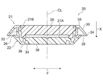
- FIG. 3 is a cross-sectional view taken along the line 3-3 of the hole plug shown in FIG.
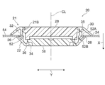
- FIG. 3 is a cross-sectional view (cross-sectional view corresponding to FIG. 3) showing a state in which the hole plug shown in FIG. 3 is inserted into the through hole.
- FIG. 3 shows the state which attached the hole plug shown in FIG. 1 to the door for a vehicle.
- FIG. 3 is a front view of the light indicator for a vehicle which concerns on other embodiment of this disclosure.
- FIG. 6 is a cross-sectional view taken along the line 7-7 of the light indicator for a vehicle shown in FIG. It is a front view of the light indicator for a vehicle which concerns on other embodiment of this disclosure.
- 9 is a sectional view taken along line 9-9 of the light indicator for a vehicle shown in FIG.
- the hole plug 20 of the present embodiment closes the through hole 52 for internal work formed in the vehicle door (specifically, the side door) 50 as an example of the vehicle component. It is a plug member for the purpose. Specifically, the hole plug 20 closes the through hole 52 formed in the vehicle rear side end portion 54A of the door inner panel 54 constituting the vehicle interior side of the vehicle door 50.
- the arrow X shown in FIGS. 3 and 4 indicates one of the axial directions of the hole plug 20, and here, the insertion direction (hereinafter, appropriately referred to as “plug insertion direction”). Further, the arrow Y shown in FIGS.
- FIGS. 3 and 4 indicate the radial direction of the hole plug 20 (hereinafter, appropriately referred to as “plug radial direction”), and the arrow Z indicates the circumferential direction of the hole plug 20 (hereinafter, appropriately referred to as appropriate). It is described as “plug circumferential direction”).
- reference numeral CL shown in FIGS. 3 and 4 indicates the central axis of the hole plug 20.
- the inner side in the radial direction of the plug refers to the side close to the central axis CL along the radial direction of the plug, and the outer side in the radial direction of the plug refers to the side far from the central axis CL along the radial direction of the plug.
- the hole plug 20 has a closing portion 22, a flange portion 24, a claw portion 26, a first marking portion 28 as a light reflecting portion, and a second marking portion as a light emitting portion. It is provided with a unit 30.
- the closing portion 22 is a portion of the hole plug 20 that closes the through hole 52 of the door inner panel 54.
- the closing portion 22 is inserted into the through hole 52 of the door inner panel 54 to close the through hole 52.
- the closed portion 22 has a cylindrical outer peripheral wall portion 32 and a cylindrical inner peripheral wall arranged concentrically with the outer peripheral wall portion 32 inside the outer peripheral wall portion 32.
- the connecting wall portion 36 connecting the portion 34, the end portion of the outer peripheral wall portion 32 on the plug insertion direction side, and the end portion of the inner peripheral wall portion 34 on the plug insertion direction side, and the inner peripheral wall portion 34 on the side opposite to the plug insertion direction. It has a bottom portion 38 that is bridged over the end portion and closes the inside of the inner peripheral wall portion 34.
- the "cylindrical shape" in the present embodiment includes those having a perfect circle and an elliptical cross-sectional shape.
- the flange portion 24 is a portion of the hole plug 20 that covers the peripheral portion of the through hole 52 of the door inner panel 54. As shown in FIGS. 1 and 3, the flange portion 24 projects outward in the plug radial direction from the end portion of the outer peripheral wall portion 32 opposite to the plug insertion direction, and has an annular shape.
- the outer diameter of the flange portion 24 is larger than the hole diameter of the through hole 52. Therefore, when the closing portion 22 of the hole plug 20 is inserted into the through hole 52 of the door inner panel 54 and the claw portion 26 described later is hooked on the edge portion 52B of the through hole 52, the closing portion 22 creates the through hole 52. It is closed and the peripheral portion of the through hole 52 is covered (see FIG. 4). That is, the hole plug 20 blindfolds the through hole 52 of the door inner panel 54 and the peripheral portion of the through hole 52.
- the claw portion 26 is a portion for attaching the hole plug 20 to the vehicle door 50. Specifically, the claw portion 26 is inserted into the through hole 52 of the door inner panel 54 and is locked to the edge portion of the through hole 52 (in other words, the portion forming the through hole 52 of the door inner panel 54) 52B. It is the part to be done.
- the claw portion 26 of the present embodiment is an example of the locking portion in the present disclosure.
- a plurality of the claw portions 26 are formed on the outer peripheral surface of the outer peripheral wall portion 32 at intervals in the circumferential direction of the plug. Further, since the claw portion 26 abuts on the edge portion 52A of the through hole 52 and elastically deforms when the closing portion 22 is inserted into the through hole 52 of the door inner panel 54, the closing portion 22 is easily inserted into the through hole 52. can. On the other hand, when a force in the pulling direction acts on the closing portion 22, the claw portion 26 is caught on the edge portion 52B of the through hole 52 (in other words, the claw portion 26 is locked to the edge portion 52B), so that the through hole 52 The obstruction portion 22 is suppressed from coming off.
- the closing portion 22, the flange portion 24, and the claw portion 26 are integrally formed to form the base member 21.
- the base member 21 is an integrally molded product of a resin made of an elastically deformable resin material.
- the base member 21 is provided with a recess 21A at a position corresponding to the closed portion 22 on the surface side.
- the recess 21A is composed of an inner peripheral wall portion 34 and a bottom portion 38 of the base member 21.
- the first marking portion 28 is fitted into the recess 21A.
- the inner peripheral wall portion 34 constituting the concave wall of the concave portion 21A is provided with a stopper portion 21B protruding inward in the radial direction.
- the first marking portion 28 is a portion of the hole plug 20 that reflects light.
- the first marking portion 28 contains a reflective material, and is adapted to specularly reflect, retroreflect, or diffusely reflect the incident light.
- the reflective material contained in the first marking unit 28 it is preferable to use a retroreflective material.
- the first marking portion 28 has a reflector made of a retroreflective material. Therefore, the first marking unit 28 of the present embodiment retroreflects the irradiated light.
- the first marking portion 28 has a disk shape or a columnar shape.
- the first marking portion 28 is provided on the side opposite to the insertion side of the closing portion 22 of the base member 21. Specifically, the first marking portion 28 is provided at a position corresponding to the closing portion 22 on the surface side of the base member 21. Specifically, the first marking portion 28 is fitted in the recess 21A of the base member 21. That is, the first marking portion 28 is removable from the base member 21.
- a ridge portion 35 extending along the circumferential direction is provided on the outer peripheral surface of the first marking portion 28 .
- the ridge portion 35 is located between the bottom portion 38 and the stopper portion 21B, and the ridge portion 35 and the stopper portion 21B are in contact with each other. Therefore, the first marking portion 28 is suppressed from coming off from the base member 21. That is, the ridge portion 35 and the stopper portion 21B maintain the state in which the first marking portion 28 is fitted in the recess 21A of the base member 21.
- the second marking unit 30 is a portion of the hole plug 20 that receives light and emits light.
- the second marking unit 30 contains a light emitting material and is adapted to emit light by incident light.
- the light emitting material contained in the second marking unit 30 it is preferable to use a fluorescent material or a phosphorescent material.
- the second marking portion 30 is made of a resin material containing a fluorescent material. Therefore, the second marking unit 30 of the present embodiment emits light when it receives light.
- the second marking unit 30 is provided adjacent to the first marking unit 28 as shown in FIGS. 1 and 3.
- the second marking portion 30 is provided in an annular shape along the flange portion 24.
- the first marking portion 28 is surrounded by the annular second marking portion 30.
- the "ring" in the present embodiment includes an annular ring having a circular outer shape, an elliptical ring having an elliptical outer shape, and a polygonal ring having a polygonal outer shape (for example, a triangle or a rectangle).
- the entire flange portion 24 is designated as the second marking portion 30.
- the base member 21 of the present embodiment is made of a resin material containing the same light emitting material (fluorescent material in the present embodiment) as the second marking portion 30, the base member 21 is manufactured at the time of manufacturing the base member 21. It becomes easy to equip 21 with the second marking unit 30.
- the present disclosure is not limited to the above configuration.
- the surface portion of the flange portion 24 may be used as the second marking portion 30.
- the hole plug 20 of the present embodiment will be described.
- the hole plug 20 when the closing portion 22 is inserted into the through hole 52 while pushing the bottom portion 38 of the closing portion 22 through the first marking portion 28 mounted on the base member 21, the restored claw portion 26 is released. It is hooked on the edge portion 52B of the through hole 52, and the hole plug 20 is locked to the through hole 52 of the door inner panel 54.
- the hole plug 20 blindfolds and stops water in the through hole 52 of the door inner panel 54 and its peripheral portion.
- the hole plug 20 is attached to the vehicle door 50 by a simple operation of inserting the closing portion 22 into the through hole 52 of the vehicle door 50 and hooking (in other words, locking) the claw portion 26 to the edge portion 52B. Since it can be attached, it can be easily attached to the vehicle door 50.
- a first marking portion 28 containing a reflective material is provided on the side opposite to the plug insertion side of the closing portion 22. Since the light (incident light) is reflected by the first marking unit 28, the hole plug 20 can be visually recognized even from a long distance at night. That is, the hole plug 20 is superior in visibility at night as compared with, for example, a hole plug 20 having no first marking portion 28 containing a reflective material.
- the first marking section 28 contains a retroreflective material, that is, the first marking section 28 has retroreflective properties. In this way, in the hole plug 20, the light incident on the first marking unit 28 is bounced off as it is to the light source, so that the first marking unit 28 (that is, the hole plug 20) can be easily visually recognized even from a long distance at night.
- a second marking portion 30 is provided adjacent to the first marking portion 28. Since the second marking unit 30 contains a light emitting material (fluorescent material in this embodiment), it emits light by receiving light even without power supply. In particular, in the present embodiment, since the second marking portion 30 contains a fluorescent material, the emission intensity is high and the visibility at night is improved.
- a light emitting material fluorescent material in this embodiment
- the first marking portion 28 when the light is irradiated, the first marking portion 28 reflects the light and the second marking portion 30 emits light. Therefore, for example, one of the first marking portion 28 or the second marking portion 30.
- the area of the part that receives light and shines is larger than that of the one equipped with only. As a result, in the hole plug 20, the area of the portion that receives light and shines becomes large, so that the visibility at night is excellent.
- the hole plug 20 of the present embodiment does not require power supply and has excellent visibility at night.
- the vehicle behind includes automobiles, motorcycles, motorized bicycles, bicycles, and the like.
- the second marking portion 30 is formed of the resin material containing the light emitting material (fluorescent material in the present embodiment), it is easy to use resin molding (for example, a conventionally known resin molding method).
- the second marking portion 30 can be formed on the surface.
- the annular second marking portion 30 surrounds the first marking portion 28, the outer shape of the second marking portion 30 becomes large.
- the area of the portion that receives the irradiated light and shines becomes larger than that in which the second marking portion 30 is adjacent without surrounding the first marking portion 28. Excellent visibility at night.
- the through hole 52 of the vehicle door 50 is closed by the closing portion 22 of the base member 21, and the peripheral portion of the through hole 52 of the vehicle door 50 is covered by the flange portion 24.
- the appearance around the through hole 52 of the door 50 is improved.
- the base member 21 can be attached to the vehicle door 50 by a simple operation of inserting the closing portion 22 into the through hole 52 of the vehicle door 50 and locking the claw portion 26.
- the first marking portion 28 is provided at a position corresponding to the closing portion 22 on the surface side of the base member 21, and the flange portion 24 adjacent to the first marking portion 28 is used as the second marking portion 30. ing. Therefore, the area of the portion that receives light and shines becomes large, and the visibility at night is improved.
- the first marking portion 28 is removable from the base member 21. Therefore, in the hole plug 20, the first marking portion 28 can be replaced when a problem occurs in the first marking portion 28 or the like.
- the first marking portion 28 is fitted in the recess 21A of the base member 21. Therefore, in the hole plug 20, for example, the first marking portion 28 and the flange portion 24 (that is, the second marking portion 24) are compared with the one in which the first marking portion 28 is installed on the surface of the base member in which the recess 21A is not provided. The step between the marking portion 30) and the marking portion 30) can be reduced. This improves the appearance of the hole plug 20.
- the first marking portion 28 is a disc-shaped or columnar member fitted into the recess 21A of the base member 21, but the present disclosure is not limited to this configuration.
- the first marking portion 28 may be provided on the surface portion of a disc-shaped or columnar member fitted into the recess 21A of the base member 21.
- the first marking portion 28 may be formed of a reflector, a reflective paint, a metal leaf, or the like.
- the second marking portion 30 contains a fluorescent material, but the present disclosure is not limited to this configuration.
- the second marking unit 30 may contain a phosphorescent material. In this case, since the second marking unit 30 contains the phosphorescent material, the light emission time becomes longer according to the stored light energy, and the visibility at night is improved. It should be noted that other functions and effects are the same as those of the hole plug 20 of the above-described embodiment. Further, for example, the second marking portion 30 may include a portion containing a fluorescent material and a portion containing a light-harvesting material.
- the fluorescent material-containing portion and the light-storing material-containing portion may be provided alternately along the flange portion 24, or the fluorescent material-containing portion (or the light-storing material-containing portion) may be provided radially inside the flange portion 24.
- a light-storing material-containing portion (or a fluorescent material-containing portion) may be provided on the radial outer side of the flange portion 24.
- the hole plug 20 of the above-described embodiment has a configuration in which the first marking portion 28 has a reflector formed of a retroreflective material, but the present disclosure is not limited to this configuration.
- the first marking portion 28 may be formed of a resin material containing a powdery reflective material.
- the powdery reflective material include metal flakes and glass flakes.
- the resin material containing the powdery reflective material it is preferable to use a transparent resin material.
- the second marking portion 30 is formed of a resin material containing a light emitting material (fluorescent material), but the present disclosure is not limited to this configuration.
- the second marking portion 30 may be formed of a resin material containing a powdery reflective material.
- the powdery reflective material include metal flakes and glass flakes.
- the resin material containing the powdery reflective material it is preferable to use a transparent resin material.
- the surface layer portion of the flange portion 24 is a second marking portion 30 and the second marking portion 30 is formed of a reflector (including a retroreflective plate), a reflective paint, a reflective film (for example, a metal foil) or the like. good.
- the second marking portion 30 is formed in an annular shape along the flange portion 24, but the present disclosure is not limited to this configuration.
- a plurality of second marking portions 30 may be formed along the flange portion 24 at intervals in the plug circumferential direction.
- the second marking portion 30 is provided in an annular shape along the flange portion 24, that is, the same annular shape as the flange portion 24.
- the second marking portion 30 may have an elliptical shape or a polygonal outer shape regardless of the shape of the flange portion 24.
- the second marking portion 30 surrounds the first marking portion 28, but the present disclosure is not limited to this configuration.
- the first marking unit 28 may surround the second marking unit 30.
- the reflective material constituting the first marking portion 28 is arranged on the flange portion 24, and the resin material constituting the second marking portion 30 is fitted into the recess 21A of the base member 21.
- the first marking portion 28 is removable from the base member 21, but the present disclosure is not limited to this configuration.
- the first marking portion 28 may be made non-detachable with respect to the base member 21.
- the hole plug 20 is attached to the through hole 52 of the vehicle door (side door) 50, but the present disclosure is not limited to this configuration.
- the hole plug 20 may be attached to a through hole formed in the back door of the vehicle.
- the hole plug 20 of the above-described embodiment may be attached to a sliding vehicle door (side door).
- the hole plug 20 for the vehicle is provided with the first marking portion 28 and the second marking portion 30, but the present disclosure is not limited to this configuration.
- the vehicle optical indicator 60 (hereinafter, appropriately referred to as “optical indicator 60”) may be attached to the attachment location H different from the above-mentioned through hole 52 of the vehicle door 50.
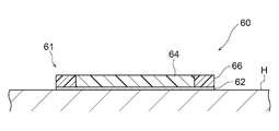
- the optical indicator 60 includes a plate-shaped base member 61 as shown in FIGS. 6 and 7.
- a mounting portion 62 is provided on one plate surface of the base member 61.
- the mounting portion 62 is an adhesive layer and can be attached to the mounting location H.
- a first marking portion 64 and a second marking portion 66 are provided adjacent to each other on the other plate surface of the base member 61.
- the second marking portion 66 has an annular shape and surrounds the first marking portion 64.
- the first marking portion 64 is made of the same material as the first marking portion 28.
- the second marking portion 66 is made of the same material as the second marking portion 30.
- the optical indicator 60 is attached to the attachment place H by attaching the attachment portion 62 to the attachment place H. Further, since the light (specifically, the incident light) is reflected by the first marking unit 64, the light marking tool 60 can be visually recognized even from a long distance at night. That is, the light indicator 60 is superior in visibility at night as compared with, for example, the one not provided with the first indicator portion 64 containing the reflective material. Further, in the optical indicator 60, a second indicator 66 is provided adjacent to the first indicator 64.
- the second marking unit 66 contains a light emitting material (fluorescent material or phosphorescent material), it emits light by receiving light even without power supply. Then, in the light indicator 60, when the light is irradiated, the first indicator 64 reflects the light and the second indicator 66 emits light. Therefore, for example, one of the first indicator or the second indicator 66.
- the area of the part that receives light and shines is larger than that of the one equipped with only. As described above, in the light indicator 60, the area of the portion that receives the light and shines becomes large, so that the visibility at night is excellent. From the above, the optical indicator 60 does not require power supply and has excellent visibility at night.
- the second indicator 66 surrounds the first indicator 64, but the present disclosure is not limited to this configuration.
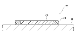
- the first indicator 74 may surround the second indicator 76. ..
- the first marking portion 74 is made of the same material as the first marking portion 28.
- the second marking portion 76 is made of the same material as the second marking portion 30.
- the attachment portion 62 is used as an adhesive layer, but the present invention is not limited to this configuration as long as the base member 61 of the optical indicator 60 is attached to the vehicle door 50.
- the mounting portion 62 may be used as a screw hole for screwing.
- Appendix 1 Mounting parts that can be attached to vehicle components A first marking portion provided on the side opposite to the mounting side of the mounting portion and containing a reflective material, and a first marking portion. A second marking portion provided adjacent to the first marking portion and containing a light emitting material, and a second marking portion. Light indicator for vehicles equipped with.
- the vehicle optical indicator of Appendix 1 can be attached to the vehicle component by attaching the mounting portion to the vehicle component.
- a first marking portion containing a reflective material is provided on the side opposite to the mounting side of the mounting portion.
- a second indicator is provided adjacent to the first indicator. Since this second marking portion contains a light emitting material, it emits light by receiving light even if there is no power supply.
- the first marking portion when the light is irradiated, the first marking portion reflects the light and the second marking portion emits light. Therefore, for example, only one of the first marking portion or the second marking portion is emitted.
- the area of the part that receives light and shines is larger than that of the one provided with. As described above, in the above-mentioned light indicator for vehicles, the area of the portion that receives light and shines becomes large, so that the visibility at night is excellent.
- the light indicator for vehicles in Appendix 1 does not require power supply and has excellent visibility at night.
- Appendix 2 The vehicle optical marking tool according to Appendix 1, wherein the second marking portion is made of a resin material containing the light emitting material.
- the second marking portion is formed of a resin material containing a light emitting material
- the second marking portion can be easily formed by resin molding (for example, a conventionally known resin molding method). Can be formed.
- Appendix 3 The vehicle optical indicator according to Appendix 1 or Appendix 2, wherein the light emitting material is a fluorescent material or a phosphorescent material.
- the second indicator since the second indicator contains a fluorescent material or a phosphorescent material, the second indicator emits light when it receives light even if there is no power supply.
- the first marking portion contains a retroreflective material, that is, the first marking portion has retroreflective property.
- the first indicator that is, the vehicle optical indicator
- a first marking portion provided on the side opposite to the mounting side of the mounting portion and specularly or retroreflecting the incident light
- a second marking unit which is provided adjacent to the first marking unit and emits light by incident light or diffusely reflects the incident light
- a second marking unit Light indicator for vehicles equipped with.
- the vehicle optical indicator of Appendix 5 is attached to the vehicle component by attaching the mounting portion to the vehicle component.
- a first marking portion that specularly or retroreflects the incident light is provided on the side opposite to the mounting side of the mounting portion. Therefore, it becomes possible to visually recognize the first marking unit (light marking tool for vehicles) even from a long distance at night. That is, the vehicle light marking tool is superior in visibility at night as compared with, for example, a device having no first marking portion that specularly or retroreflects the incident light.
- a second indicator is provided adjacent to the first indicator.
- This second marking unit emits light by the incident light or diffusely reflects the incident light even if there is no power supply.
- the first marking portion reflects the light and the second marking portion reflects or emits light. Therefore, for example, in the first marking portion or the second marking portion.
- the area of the part that receives light and shines is larger than that of the one equipped with only one. As described above, in the above-mentioned light indicator for vehicles, the area of the portion that receives light and shines becomes large, so that the visibility at night is excellent.
- the light indicator for vehicles in Appendix 5 does not require power supply and has excellent visibility at night.
- the annular second marking portion surrounds the first marking portion, the outer shape of the second marking portion becomes large.
- the area of the portion that receives light and shines is larger than that in which the second marking portion is adjacent without surrounding the first marking portion, so that the area of the portion that shines is larger at night. Excellent visibility.
- a closed portion that is inserted into a through hole formed in the vehicle component to close the through hole, a flange portion that is integrally formed with the closed portion and covers the peripheral portion of the through hole of the vehicle constituent member, and the flange portion. It comprises a base member having a locking portion as the mounting portion, which is formed integrally with the closing portion and is inserted into and locked in the through hole.
- the first marking portion is provided at a position corresponding to the closed portion on the surface side of the base member.
- the through hole formed in the vehicle component is closed by the closing portion of the base member, and the peripheral portion of the through hole of the vehicle component is covered by the flange portion.
- the appearance around the through hole is improved.
- the base member can be attached to the vehicle constituent member by a simple operation of inserting the locking portion as the attachment portion into the through hole of the vehicle constituent member and locking the portion.
- the first marking portion is provided at a position corresponding to the closed portion on the surface side of the base member, and the second marking portion is provided on the flange portion adjacent to the first marking portion. .. Therefore, the area of the portion that receives light and shines becomes large, and the visibility at night is improved.
- a closed portion that is inserted into a through hole formed in a vehicle component to close the through hole, a flange portion that is integrally formed with the closed portion and covers the peripheral portion of the through hole of the vehicle constituent member, and the closed portion.
- a base member having a locking portion as a mounting portion that is integrally formed with the portion and is inserted into and locked in the through hole.
- a first marking portion provided at a position corresponding to the closed portion on the surface side of the base member and reflecting incident light, and a first marking portion.
- a second marking portion provided on the flange portion, which emits light or reflects the incident light by the incident light, and a second marking portion.
- the through hole formed in the vehicle component is closed by the closing portion of the base member, and the peripheral portion of the through hole of the vehicle component is covered by the flange portion.
- the appearance around the through hole is improved.
- the base member can be attached to the vehicle constituent member by a simple operation of inserting the locking portion into the through hole of the vehicle constituent member and locking the locking portion.
- the first indicator is provided at a position corresponding to the closed portion on the surface side of the base member. Therefore, it becomes possible to visually recognize the first marking unit (light marking tool for vehicles) even from a long distance at night. That is, the vehicle light marking tool is superior in visibility at night as compared with, for example, a device having no first marking portion for reflecting incident light.
- a second marking portion is provided on a flange portion adjacent to the first marking portion.
- the second marking unit emits light or reflects the incident light by the incident light even if there is no power supply.
- the first marking portion reflects the light
- the second marking portion emits light or reflects the light. Therefore, for example, the first marking portion or the second marking portion.
- the area of the part that receives light and shines is larger than that of the one equipped with only one. As described above, in the above-mentioned light indicator for vehicles, the area of the portion that receives light and shines becomes large, so that the visibility at night is excellent.
- the light indicator for vehicles in Appendix 8 does not require power supply and has excellent visibility at night.
- the first marking portion contains a retroreflective material, that is, the first marking portion has retroreflective property.
- the first indicator that is, the vehicle optical indicator
- the second indicator contains a light emitting material, the second indicator emits light when it receives light even if there is no power supply. Therefore, in the above-mentioned light indicator for vehicles, visibility at night is improved.
- the first marking portion contains a reflective material, the light incident on the first marking portion is reflected. Therefore, in the above-mentioned light indicator for vehicles, visibility at night is improved.
- the first indicator is removable from the base member. Therefore, in the above-mentioned optical indicator for vehicles, the first indicator can be replaced.
- a recess is provided at a position corresponding to the closed portion on the surface side of the base member.
- the first marking portion is fitted in the recess provided at the position corresponding to the closed portion on the surface side of the base member. Therefore, in the above-mentioned optical marking tool for vehicles, for example, the first marking portion and the flange portion (second marking portion) are compared with the one in which the first marking portion is installed on the surface of the base member having no recess. The step between and can be reduced. As a result, the appearance of the light indicator for vehicles is improved.
- the vehicle component is a vehicle door, and is a vehicle optical indicator according to any one of Supplementary note 1 to Supplementary note 13.
- the vehicle optical indicator is a vehicle door. Therefore, by attaching the vehicle light indicator having excellent visibility at night to the vehicle door, it becomes easier to visually recognize the open state of the vehicle door at night from the vehicle behind.
Landscapes
- Engineering & Computer Science (AREA)
- Mechanical Engineering (AREA)
- General Engineering & Computer Science (AREA)
- Physics & Mathematics (AREA)
- Electromagnetism (AREA)
- Lighting Device Outwards From Vehicle And Optical Signal (AREA)
- Vehicle Interior And Exterior Ornaments, Soundproofing, And Insulation (AREA)
Abstract
Description
なお、図3及び図4に示す矢印Xは、ホールプラグ20の軸方向の一方、ここでは、挿入方向(以下、適宜「プラグ挿入方向」と記載する。)を示している。また、図2~図4に示す矢印Yは、ホールプラグ20の径方向(以下、適宜「プラグ径方向」と記載する。)を示し、矢印Zは、ホールプラグ20の周方向(以下、適宜「プラグ周方向」と記載する。)を示している。また、図3及び図4に示す符号CLは、ホールプラグ20の中心軸を示している。なお、プラグ径方向内側とは、プラグ径方向に沿って中心軸CLに近い側を指しており、プラグ径方向外側とは、プラグ径方向に沿って中心軸CLから遠い側を指している。
閉塞部22は、図3及び図4に示されるように、ホールプラグ20において、ドアインナパネル54の貫通孔52を閉塞する部分である。この閉塞部22は、ドアインナパネル54の貫通孔52へ挿入されることで、貫通孔52を閉塞するようになっている。
フランジ部24は、図4に示されるように、ホールプラグ20において、ドアインナパネル54の貫通孔52の周辺部を覆う部分である。このフランジ部24は、図1及び図3に示されるように、外周壁部32のプラグ挿入方向と反対側の端部からプラグ径方向外側へ張り出しており、円環状とされている。
爪部26は、図3及び図4に示されるように、ホールプラグ20を車両用ドア50に取り付けるための部分である。具体的には、爪部26は、ドアインナパネル54の貫通孔52へ挿入されて、貫通孔52の縁部(言い換えると、ドアインナパネル54の貫通孔52を形成する部分)52Bに係止される部分である。なお、本実施形態の爪部26は、本開示における係止部の一例である。
第1標示部28は、図1~図4に示されるように、ホールプラグ20において、光を反射する部分である。この第1標示部28は、反射材を含有しており、入射された光を正反射、再帰性反射あるいは拡散反射するようになっている。第1標示部28が含有する反射材としては、再帰性反射材を用いることが好ましい。なお、本実施形態では、第1標示部28が再帰性反射材で構成された反射板を有している。このため、本実施形態の第1標示部28は照射された光を再帰性反射するようになっている。
第2標示部30は、図1~図4に示されるように、ホールプラグ20において、光を受けて発光する部分である。この第2標示部30は、発光材を含有しており、入射された光によって発光するようになっている。第2標示部30が含有する発光材は、蛍光材又は蓄光材を用いることが好ましい。なお、本実施形態では、第2標示部30が蛍光材を含有する樹脂材料で形成されている。このため、本実施形態の第2標示部30は光を受けると発光するようになっている。
ホールプラグ20では、ベース部材21に装着された第1標示部28を介して閉塞部22の底部38を押しながら、閉塞部22を貫通孔52に挿入していくと、復元した爪部26が貫通孔52の縁部52Bに引っ掛かり、ホールプラグ20がドアインナパネル54の貫通孔52に係止される。このようにしてホールプラグ20がドアインナパネル54に取り付けられると、ホールプラグ20によって、ドアインナパネル54の貫通孔52及びその周辺部が目隠し及び止水される。
前述の実施形態のホールプラグ20では、第1標示部28がベース部材21の凹部21Aに嵌め込まれる円板状又は円柱状の部材とされているが、本開示はこの構成に限定されない。例えば、第1標示部28は、ベース部材21の凹部21Aに嵌め込まれる円板状又は円柱状の部材の表面部分に設けられてもよい。なお、第1標示部28を円板状又は円柱状の部材の表面部分に設ける場合には、第1標示部28を、反射板、反射塗料、金属箔等で形成してもよい。
また、前述の実施形態のホールプラグ20では、第2標示部30がフランジ部24に沿って環状に設けられている、すなわち、フランジ部24と同じ円環状とされているが、本開示はこの構成に限定されない。例えば、第2標示部30は、フランジ部24の形状に関わらず、外形を楕円形あるいは多角形としてもよい。
さらに、前述の実施形態のホールプラグ20では、第2標示部30が第1標示部28を取り囲んでいるが、本開示はこの構成に限定されない。第1標示部28が第2標示部30を取り囲んでもよい。この場合には、例えば、第1標示部28を構成する反射材がフランジ部24上に配置され、第2標示部30を構成する樹脂材料がベース部材21の凹部21Aに嵌め込まれる。
車両構成部材に取り付けられる取付部と、
前記取付部の取付側と反対側に設けられ、反射材を含有する第1標示部と、
前記第1標示部に隣接して設けられ、発光材を含有する第2標示部と、
を備える車両用光標示具。
前記第2標示部は、前記発光材を含有する樹脂材料で形成されている、付記1に記載の車両用光標示具。
前記発光材は、蛍光材又は蓄光材である、付記1又は付記2に記載の車両用光標示具。
前記反射材は、再帰性反射材である、付記1~付記3のいずれか1項に記載の車両用光標示具。
車両構成部材に取り付けられる取付部と、
前記取付部の取付側と反対側に設けられ、入射された光を正反射又は再帰性反射する第1標示部と、
前記第1標示部に隣接して設けられ、入射された光によって発光又は入射された光を拡散反射する第2標示部と、
を備える車両用光標示具。
前記第2標示部は、環状とされ、前記第1標示部を取り囲んでいる、付記1~付記5のいずれか1項に記載の車両用光標示具。
なお、ここでいう「環状」には、外形が円形の円環状、外形が楕円形の楕円環状、外形が多角形(例えば、三角形や矩形)の多角形環状が含まれる。
前記車両構成部材に形成された貫通孔に挿入されて該貫通孔を塞ぐ閉塞部と、前記閉塞部と一体に形成され、前記車両構成部材の前記貫通孔の周辺部を覆うフランジ部と、前記閉塞部と一体に形成され、前記貫通孔に挿入されて係止される前記取付部としての係止部と、を有するベース部材を備え、
前記ベース部材の表面側の前記閉塞部に対応する位置に前記第1標示部が設けられ、
前記フランジ部に前記第2標示部が設けられている、付記1~付記6のいずれか1項に記載の車両用光標示具。
車両構成部材に形成された貫通孔に挿入されて該貫通孔を塞ぐ閉塞部と、前記閉塞部と一体に形成され、前記車両構成部材の前記貫通孔の周辺部を覆うフランジ部と、前記閉塞部と一体に形成され、前記貫通孔に挿入されて係止される取付部としての係止部と、を有するベース部材と、
前記ベース部材の表面側の前記閉塞部に対応する位置に設けられ、入射された光を反射する第1標示部と、
前記フランジ部に設けられ、入射された光によって発光又は入射された光を反射する第2標示部と、
を備える車両用光標示具。
前記第1標示部は、再帰性反射材を含有している、付記5又は付記7に記載の車両用光標示具。
前記第2標示部は、発光材を含有している、付記5、付記7、又は付記9のいずれか1項に記載の車両用光標示具。
前記第2標示部は、反射材を含有している、付記5、付記7、又は付記9のいずれか1項に記載の車両用光標示具。
前記第2標示部が前記ベース部材に対して着脱可能とされている、付記7又は付記8に記載の車両用光標示具。
前記ベース部材の表面側の前記閉塞部に対応する位置に凹部が設けられ、
前記第2標示部が前記凹部に嵌められている、付記12に記載の車両用光標示具。
前記車両構成部材は、車両用ドアである、付記1~付記13のいずれか1項に記載の車両用光標示具。
本明細書に記載された全ての文献、特許出願、および技術規格は、個々の文献、特許出願、および技術規格が参照により取り込まれることが具体的かつ個々に記された場合と同程度に、本明細書中に参照により取り込まれる。
Claims (14)
- 車両構成部材に取り付けられる取付部と、
前記取付部の取付側と反対側に設けられ、反射材を含有する第1標示部と、
前記第1標示部に隣接して設けられ、発光材を含有する第2標示部と、
を備える車両用光標示具。 - 前記第2標示部は、前記発光材を含有する樹脂材料で形成されている、請求項1に記載の車両用光標示具。
- 前記発光材は、蛍光材又は蓄光材である、請求項1又は請求項2に記載の車両用光標示具。
- 前記反射材は、再帰性反射材である、請求項1~請求項3のいずれか1項に記載の車両用光標示具。
- 車両構成部材に取り付けられる取付部と、
前記取付部の取付側と反対側に設けられ、入射された光を正反射又は再帰性反射する第1標示部と、
前記第1標示部に隣接して設けられ、入射された光によって発光又は入射された光を拡散反射する第2標示部と、
を備える車両用光標示具。 - 前記第2標示部は、環状とされ、前記第1標示部を取り囲んでいる、請求項1~請求項5のいずれか1項に記載の車両用光標示具。
- 前記車両構成部材に形成された貫通孔に挿入されて該貫通孔を塞ぐ閉塞部と、前記閉塞部と一体に形成され、前記車両構成部材の前記貫通孔の周辺部を覆うフランジ部と、前記閉塞部と一体に形成され、前記貫通孔に挿入されて係止される前記取付部としての係止部と、を有するベース部材を備え、
前記ベース部材の表面側の前記閉塞部に対応する位置に前記第1標示部が設けられ、
前記フランジ部に前記第2標示部が設けられている、請求項1~請求項6のいずれか1項に記載の車両用光標示具。 - 車両構成部材に形成された貫通孔に挿入されて該貫通孔を塞ぐ閉塞部と、前記閉塞部と一体に形成され、前記車両構成部材の前記貫通孔の周辺部を覆うフランジ部と、前記閉塞部と一体に形成され、前記貫通孔に挿入されて係止される取付部としての係止部と、を有するベース部材と、
前記ベース部材の表面側の前記閉塞部に対応する位置に設けられ、入射された光を反射する第1標示部と、
前記フランジ部に設けられ、入射された光によって発光又は入射された光を反射する第2標示部と、
を備える車両用光標示具。 - 前記第1標示部は、再帰性反射材を含有している、請求項5又は請求項7に記載の車両用光標示具。
- 前記第2標示部は、発光材を含有している、請求項5、請求項7、又は請求項9のいずれか1項に記載の車両用光標示具。
- 前記第2標示部は、反射材を含有している、請求項5、請求項7、又は請求項9のいずれか1項に記載の車両用光標示具。
- 前記第2標示部が前記ベース部材に対して着脱可能とされている、請求項7又は請求項8に記載の車両用光標示具。
- 前記ベース部材の表面側の前記閉塞部に対応する位置に凹部が設けられ、
前記第2標示部が前記凹部に嵌められている、請求項12に記載の車両用光標示具。 - 前記車両構成部材は、車両用ドアである、請求項1~請求項13のいずれか1項に記載の車両用光標示具。
Priority Applications (2)
| Application Number | Priority Date | Filing Date | Title |
|---|---|---|---|
| US18/268,663 US20240042922A1 (en) | 2020-12-24 | 2021-12-13 | Vehicle-light marking tool |
| CN202180086778.7A CN116648580A (zh) | 2020-12-24 | 2021-12-13 | 车用光标示器 |
Applications Claiming Priority (2)
| Application Number | Priority Date | Filing Date | Title |
|---|---|---|---|
| JP2020-215841 | 2020-12-24 | ||
| JP2020215841A JP7517982B2 (ja) | 2020-12-24 | 2020-12-24 | 車両用光標示具 |
Publications (1)
| Publication Number | Publication Date |
|---|---|
| WO2022138296A1 true WO2022138296A1 (ja) | 2022-06-30 |
Family
ID=82159650
Family Applications (1)
| Application Number | Title | Priority Date | Filing Date |
|---|---|---|---|
| PCT/JP2021/045887 Ceased WO2022138296A1 (ja) | 2020-12-24 | 2021-12-13 | 車両用光標示具 |
Country Status (4)
| Country | Link |
|---|---|
| US (1) | US20240042922A1 (ja) |
| JP (1) | JP7517982B2 (ja) |
| CN (1) | CN116648580A (ja) |
| WO (1) | WO2022138296A1 (ja) |
Citations (2)
| Publication number | Priority date | Publication date | Assignee | Title |
|---|---|---|---|---|
| JPS6125212U (ja) * | 1984-07-20 | 1986-02-14 | 秀雄 増淵 | 再帰反射材付き自動車ドア |
| JP2020152253A (ja) * | 2019-03-20 | 2020-09-24 | トヨタ車体株式会社 | ホールプラグ |
Family Cites Families (5)
| Publication number | Priority date | Publication date | Assignee | Title |
|---|---|---|---|---|
| JP2948500B2 (ja) * | 1994-03-16 | 1999-09-13 | 有限会社完装 | 駐車場の車両誘導案内体構造 |
| BR112016022165B1 (pt) * | 2014-03-26 | 2022-06-28 | Nissan Motor Co. Ltd | Dispositivo de apresentação de informações de veículo |
| TWM548094U (zh) * | 2017-05-03 | 2017-09-01 | Keng Lien Industrial Co Ltd | 車門孔塞 |
| JP2019106259A (ja) * | 2017-12-11 | 2019-06-27 | 東芝ライテック株式会社 | 車両用照明装置、車両用照明装置の製造方法、および車両用灯具 |
| JP7262045B2 (ja) * | 2019-05-21 | 2023-04-21 | 伸 唐沢 | 路面マーカー、路面マーカーセット |
-
2020
- 2020-12-24 JP JP2020215841A patent/JP7517982B2/ja active Active
-
2021
- 2021-12-13 US US18/268,663 patent/US20240042922A1/en active Pending
- 2021-12-13 WO PCT/JP2021/045887 patent/WO2022138296A1/ja not_active Ceased
- 2021-12-13 CN CN202180086778.7A patent/CN116648580A/zh active Pending
Patent Citations (2)
| Publication number | Priority date | Publication date | Assignee | Title |
|---|---|---|---|---|
| JPS6125212U (ja) * | 1984-07-20 | 1986-02-14 | 秀雄 増淵 | 再帰反射材付き自動車ドア |
| JP2020152253A (ja) * | 2019-03-20 | 2020-09-24 | トヨタ車体株式会社 | ホールプラグ |
Also Published As
| Publication number | Publication date |
|---|---|
| US20240042922A1 (en) | 2024-02-08 |
| JP2022101325A (ja) | 2022-07-06 |
| JP7517982B2 (ja) | 2024-07-17 |
| CN116648580A (zh) | 2023-08-25 |
Similar Documents
| Publication | Publication Date | Title |
|---|---|---|
| US7319244B2 (en) | Lens assembly for sideward light emission | |
| US7093964B2 (en) | Compact, low-level vehicle interior lamp assembly | |
| US8147110B2 (en) | Light pipe assembly | |
| EP2302426B1 (en) | Light pipe providing wide illumination angle | |
| CN102959314A (zh) | 照明装置 | |
| CN108700280A (zh) | 具有互锁附接特征的塑料筒灯装置 | |
| WO2022138296A1 (ja) | 車両用光標示具 | |
| CN105190157A (zh) | 用于定向灯的光学系统 | |
| US7399106B2 (en) | Lens optics used to reduce part deformation due to heat | |
| EP2926049A1 (fr) | Dispositif de signalisation pour véhicule avec effet tridimensionnel | |
| JPH1137133A (ja) | 合成樹脂製ワッシャ | |
| US20130114281A1 (en) | Vehicle lamp structure | |
| JP7131762B2 (ja) | ホールプラグ | |
| JP4484753B2 (ja) | マーカーランプ | |
| US9869444B2 (en) | Flat lamp structure | |
| JP2016184548A (ja) | 車両用灯具 | |
| JP2003151313A5 (ja) | ||
| JP2006173031A (ja) | 車両用照明装置 | |
| JP7684855B2 (ja) | 自発光視線誘導標 | |
| JP4866444B2 (ja) | 車両用灯具における導光体の取付け構造 | |
| JP2013049345A (ja) | 車両用ドアミラー | |
| JP2000215708A (ja) | 自動車用灯具 | |
| JPH11305697A (ja) | 光反射器 | |
| EP4671605A1 (en) | VEHICLE LAMP | |
| JP2007118643A (ja) | 自動車用発光バイザー |
Legal Events
| Date | Code | Title | Description |
|---|---|---|---|
| 121 | Ep: the epo has been informed by wipo that ep was designated in this application |
Ref document number: 21910445 Country of ref document: EP Kind code of ref document: A1 |
|
| WWE | Wipo information: entry into national phase |
Ref document number: 202180086778.7 Country of ref document: CN Ref document number: 18268663 Country of ref document: US |
|
| NENP | Non-entry into the national phase |
Ref country code: DE |
|
| 122 | Ep: pct application non-entry in european phase |
Ref document number: 21910445 Country of ref document: EP Kind code of ref document: A1 |