WO2022137576A1 - チップソー - Google Patents
チップソー Download PDFInfo
- Publication number
- WO2022137576A1 WO2022137576A1 PCT/JP2021/006559 JP2021006559W WO2022137576A1 WO 2022137576 A1 WO2022137576 A1 WO 2022137576A1 JP 2021006559 W JP2021006559 W JP 2021006559W WO 2022137576 A1 WO2022137576 A1 WO 2022137576A1
- Authority
- WO
- WIPO (PCT)
- Prior art keywords
- cutting edge
- piece
- tip saw
- support piece
- base metal
- Prior art date
- Legal status (The legal status is an assumption and is not a legal conclusion. Google has not performed a legal analysis and makes no representation as to the accuracy of the status listed.)
- Ceased
Links
Images


Classifications
-
- B—PERFORMING OPERATIONS; TRANSPORTING
- B27—WORKING OR PRESERVING WOOD OR SIMILAR MATERIAL; NAILING OR STAPLING MACHINES IN GENERAL
- B27B—SAWS FOR WOOD OR SIMILAR MATERIAL; COMPONENTS OR ACCESSORIES THEREFOR
- B27B33/00—Sawing tools for saw mills, sawing machines, or sawing devices
- B27B33/02—Structural design of saw blades or saw teeth
- B27B33/08—Circular saw blades
-
- B—PERFORMING OPERATIONS; TRANSPORTING
- B23—MACHINE TOOLS; METAL-WORKING NOT OTHERWISE PROVIDED FOR
- B23D—PLANING; SLOTTING; SHEARING; BROACHING; SAWING; FILING; SCRAPING; LIKE OPERATIONS FOR WORKING METAL BY REMOVING MATERIAL, NOT OTHERWISE PROVIDED FOR
- B23D61/00—Tools for sawing machines or sawing devices; Clamping devices for these tools
- B23D61/02—Circular saw blades
- B23D61/025—Details of saw blade body
- B23D61/026—Composite body, e.g. laminated
Definitions
- the present invention relates to a tip saw in which a cutting edge piece such as a tip is provided on the cutting edge portion of a circular saw.
- FIG. 29 is a plan view showing a state in which a pipe-shaped work material is cut using a conventional tip saw.
- FIG. 30 is an enlarged view showing a range surrounded by the alternate long and short dash line vii in FIG. 29.
- the hardness of the super hard alloy is higher than that of high-speed tool steel (high-speed steel, high-speed steel), and the hardness does not decrease at high temperatures. Therefore, it cuts well when used for the cutting edge portion of a cutting tool.
- a tip saw 1 having a cutting edge piece 1a made of cemented carbide attached to a cutting edge portion has been widely used.
- the cutting edge piece 1a is configured to be wider than the base metal 1A.
- FIG. 31 is a plan view showing a conventional tip saw described in Patent Document 1.
- FIG. 31 is the same diagram as FIG. 1 of Patent Document 1.
- Patent Document 1 describes a tip saw 2 (circular saw) for vertical grinding of wood.
- the tip saw 2 has a first cutting edge piece 2a (insert body) and a second cutting edge piece 2b (insert body, facing element or insert body).
- the first cutting edge piece 2a and the second cutting edge piece 2b are made of cemented carbide.
- the first cutting edge piece 2a is attached to the cutting edge portion of the tip saw 2, and the second cutting edge piece 2b is attached to the edge portion of the groove 2s (slot) arranged between the cutting edge portions.
- the grooves 2s extend inward in the radial direction, and are formed one on each side of the rotation center O of the tip saw 2. Therefore, like the groove 2s, the second cutting edge piece 2b is provided one on each side of the rotation center O of the tip saw 2.
- FIG. 32 is a plan view showing a conventional tip saw described in Patent Document 2.
- FIG. 32 is the same diagram as FIG. 5 of Patent Document 2.
- Patent Document 2 describes a tipped saw 3 (circular saw) suitable for cutting wood and wood panels.
- the tip saw 3 has a first cutting edge piece 3a (tip insert), a second cutting edge piece 3b (second wiper tip), and a third cutting edge piece 3c (first wiper tip).
- the first cutting edge piece 3a, the second cutting edge piece 3b, and the third cutting edge piece 3c are made of cemented carbide.
- the first cutting edge piece 3a is attached to the cutting edge portion.
- Three second cutting edge pieces 3b are provided on the tip saw 3 and are attached to the edge of the groove 3s (expansion slit) between the cutting edge portions.
- the grooves 3s extend inward in the radial direction, and six grooves are formed around the center of rotation O at predetermined angular intervals.
- the second cutting edge piece 3b is provided around the rotation center O at every other groove 3s.
- Three third cutting edge pieces 3c are provided on the tip saw 3 and are attached to the edge of the elongated hole 3h (opening) of the base metal 3A (base disk).
- the cutting edge piece 1a is cut. Is configured to be wider than the base metal 1A, so that the cutting edge of the cutting edge piece 1a cuts the work material P to form a cutting groove Pc, and the cutting edge piece 1a is inserted into the cutting groove Pc. Then, the width length of the cutting groove Pc is maintained the same as the thickness of the cutting edge piece 1a, but if the cutting edge piece 1a is not inserted into the cutting groove Pc, the width length of the cutting groove Pc becomes the thickness of the base metal 1A.
- the width length of the cut groove Pc of the work material P fluctuates depending on whether it becomes large or small, so that the cut surface of the work material P becomes dirty. There is.
- the present invention solves the above-mentioned problems, and an object thereof is to provide a tipped saw capable of obtaining a clean cut surface when cutting a hollow work material.
- the tip saw of the present invention is a disk-shaped tip saw having a cutting edge piece at the cutting edge portion, and a support piece is arranged between two adjacent cutting edge pieces.
- the cutting edge piece and the support piece are configured to have a width wider than the thickness of the base metal of the tip saw, and the support piece has a thickness equal to or close to the thickness of the cutting edge piece. do.
- the present invention is a disk-shaped tip saw having a cutting edge piece at the cutting edge portion, and a supporting piece is arranged between two adjacent cutting edge pieces, and the cutting edge piece and the supporting piece are arranged.
- the piece is configured to have a width wider than the thickness of the base metal of the tip saw, and the support piece has a thickness equal to or close to the thickness of the cutting edge piece, so that the support piece has the cutting edge piece. Since it has the same or nearly the same thickness as the above and is arranged between the two adjacent cutting edge pieces, the cutting edge is provided by the supporting piece without increasing the number of the cutting edge pieces of the tip saw.
- the width and length of the cutting groove formed by the piece in the work material can be maintained at the same thickness as or close to the thickness of the cutting edge piece.
- the support piece is arranged so as to include at least a central position or a position near the center position between two adjacent cutting edge pieces.
- the support pieces are arranged so as to include at least a central position or a position near the center position between the two adjacent cutting edge pieces, so that the two support pieces are adjacent to each other. Adjacent cutting blades as compared to the case where one of the blade pieces is offset and a part of the supporting piece is not arranged at the center position or a near position between two adjacent cutting edge pieces. The variation in the distance between the piece and the support piece can be reduced.
- the case where the support piece is arranged so as to include at least a central position between two adjacent cutting edge pieces or a position near the center position includes the following cases.
- the entire support piece is offset to one of two adjacent cutting edge pieces, and a part of the support piece is placed at or near the center position between the two adjacent cutting edge pieces. If it has been.
- a part of the support piece overlaps with one of the two adjacent cutting edge pieces in the circumferential direction, and the other part of the support piece is at the center position between the two adjacent cutting edge pieces or the center position thereof. If it is located near you.
- both ends of the support piece may overlap both of the two adjacent cutting edge pieces in the circumferential direction.
- the support piece extends so as to overlap with the cutting edge piece adjacent to the reverse rotation side of the tip saw in the circumferential direction.
- the support piece extends so as to overlap the cutting edge piece adjacent to the reverse rotation side of the tip saw in the circumferential direction, so that the support piece and the tip saw are reversed when the tip saw is viewed from the outer periphery. Since the cutting edge piece adjacent to the rotating side is arranged adjacent to the cutting edge piece, the portion wider than the base metal of the tip saw can be continuously connected from the supporting piece to the cutting edge piece adjacent to the reverse rotating side of the tip saw without a gap. can.
- the support piece is attached to the outside of the base metal. According to the present invention, since the support piece is attached to the outside of the base metal, the strength of the base metal is lowered as compared with the case where the support piece is provided inside the base metal. Tipped saws can be manufactured easily and at low cost without any need.
- the outside of the base metal is the outside from the outer peripheral edge of the base metal.
- the tooth portion and the recess provided on the outer peripheral portion of the tip saw are a part of the base metal. Therefore, the outside of the base metal includes the outside of the tooth portion, and the outside of the recess is also included.
- the support piece is provided inside the base metal. According to the present invention, since the support piece is provided inside the base metal, the recess of the tip saw is not narrowed as compared with the case where the support piece is attached to the outside of the base metal. Therefore, it is possible to prevent the chip saw from deteriorating the chip discharge property.
- the inside of the base metal is the inside in the radial direction from the outer peripheral edge of the base metal.
- the tooth portion and the recess provided on the outer peripheral portion of the tip saw are a part of the base metal. Therefore, the inside of the base metal includes the inside of the tooth portion and the inside of the recess.
- the cutting edge piece and the support piece are made of different materials. According to the present invention, since the cutting edge piece and the supporting piece are made of different materials, the material cost of the supporting piece is reduced from the material cost of the cutting edge piece, and the manufacturing cost of the tip saw is reduced. Can be reduced.
- the tip saw of the present invention is a disk-shaped tip saw having a cutting edge portion on the cutting edge portion, and the cutting edge piece extends to the reverse rotation side of the tip saw, and the cutting edge of the tip saw provided with the cutting edge is cut on the rotation side. It has a blade portion and a support portion on the reverse rotation side of the tip saw, and the cutting edge piece is characterized in that it is configured to be wider than the base metal of the tip saw from the cutting edge portion to the support portion.
- the present invention is a disk-shaped tip saw having a cutting edge portion on the cutting edge portion, and the cutting edge piece extends to the reverse rotation side of the tip saw, and the cutting edge of the tip saw provided with the cutting edge is cut on the rotating side. It has a blade portion and a support portion on the reverse rotation side of the tip saw, and the cutting edge piece is configured to be wider than the base metal of the tip saw from the cutting blade portion to the support portion, so that it is covered by the tip saw.
- the cutting edge portion and the supporting portion of the cutting edge piece are sequentially and continuously inserted into the cutting groove formed in the cutting material by the cutting edge piece without any gap.
- the width of the cutting groove of the work material can be held longer than that of the base metal of the tip saw, as compared with the case where the blade is arranged between the two adjacent cutting edge pieces.
- the supporting portion of the cutting edge piece extends to a central position between at least one cutting edge and the other cutting edge of two adjacent cutting edge pieces.
- the support portion of the cutting edge piece extends to a central position between at least one cutting edge and the other cutting edge in two adjacent cutting edge pieces. Compared with the case where the support portion of the cutting edge piece does not reach the central position, the width length of the cut groove of the work material can be maintained for a long time.
- the two adjacent cutting edge pieces partially overlap each other in the circumferential direction.
- the two adjacent cutting edge pieces partially overlap each other in the circumferential direction, so that the two adjacent cutting edge pieces are arranged adjacent to each other when the tip saw is viewed from the outer circumference, and the cutting edge pieces are the tip saw. Since it surrounds the base metal in a circumferential shape without gaps, when cutting the work material, the cutting edge pieces can be continuously inserted into the cutting groove formed in the work material without any gaps. The width and length of the cut groove can be maintained at all times.
- the cutting edge piece is made of a material in which the cutting edge portion and the supporting portion are different from each other. According to the present invention, since the cutting edge piece is made of a material in which the cutting edge portion and the supporting portion are different from each other, the material cost of the supporting portion is reduced from the material cost of the cutting edge portion. The manufacturing cost of the tip saw can be reduced.
- the present invention is a disk-shaped tip saw having a cutting edge piece at the cutting edge portion, and the supporting piece is arranged between two adjacent cutting edge pieces, or. Since the cutting edge piece includes a support portion extending to the reverse rotation side of the tip saw, when the work material is cut by the tip saw, the support piece or the support piece or the support piece is inserted in the cutting groove formed by the cutting edge piece in the work material. By inserting the support portion, it is possible to obtain an excellent effect that the width and length of the cut groove of the work material can be maintained.
- FIG. 6 is an enlarged view showing a range surrounded by the alternate long and short dash line ii in FIG. It is a top view which shows the tip saw of 2nd Embodiment.
- FIG. 6 is an enlarged view showing a range surrounded by the alternate long and short dash line iii in FIG.
- FIG. 9 is an enlarged view showing a range surrounded by the alternate long and short dash line iv in FIG. 9.
- FIG. 11 is an enlarged view showing a range surrounded by the alternate long and short dash line v in FIG. 11.
- FIG. 11 is a schematic end view which shows the state seen from the arrow L3 of FIG.
- FIG. 11 is a schematic plan view which shows the state which cuts the hollow work material by the tip saw of 3rd Embodiment.
- 14 is an enlarged view showing a range surrounded by the alternate long and short dash line vi. It is an enlarged view which shows the outer peripheral part of another tipped saw which concerns on 1st Embodiment. It is an enlarged view which shows the outer peripheral part of another tipped saw which concerns on 1st Embodiment. It is an enlarged view which shows the outer peripheral part of another tipped saw which concerns on 2nd Embodiment. It is an enlarged view which shows the outer peripheral part of the other tipped saw which concerns on 2nd Embodiment. It is an enlarged view which shows the outer peripheral part of another tipped saw which concerns on 2nd Embodiment.
- FIG. 29 is an enlarged view showing a range surrounded by the alternate long and short dash line vii. It is a top view which shows the tip saw described in Patent Document 1. FIG. It is a top view which shows the tip saw described in Patent Document 2. FIG.
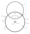
- FIG. 1 is a plan view of the tip saw of the first embodiment according to the present invention.
- the tip saw 10 is a disk-shaped circular saw, and has a base metal 11, a cutting edge piece 12, and a support piece 13.
- the direction indicated by the arrow Rt is the rotation side of the tip saw (in FIGS. 1, 4, 6, 9, 11, and 14, the side that rotates counterclockwise with respect to the rotation center O. , FIG. 2, FIG. 3, FIG. 7, FIG. 12, FIG. 13 and FIGS. 16 to 28 are on the left side of the paper, and FIGS. 5 and 10 and 15 are on the upper left side of the paper).
- the direction indicated by the arrow Rv is the reverse rotation side of the tip saw (in FIGS. 1, 4, 6, 9, 11 and 14, the side that rotates clockwise around the rotation center O, FIGS. 2 and 3). 7 and 12 and 13 and 16 to 28 are on the right side of the paper, and 5 and 10 and 15 are on the lower right side of the paper).
- the direction indicated by the arrow Ot is the radial side of the tip saw (the side away from the rotation center O in FIGS. 1, 4, 6, 9, 11 and 14, and FIGS. 2, 7, 12, and 16).
- the direction indicated by the arrow In is the inside of the tip saw in the radial direction (in FIGS. 1, 4, 6, 9, 11 and 14, the side closer to the rotation center O, FIG. 2, FIG. 7, FIG. 12, and FIG. -The lower side of the paper surface in FIG. 28, the back side of the paper surface in FIGS. 3, 8 and 13, and the lower left side of the paper surface in FIGS.
- the direction indicated by the arrow Fr is the front side of the tip saw (the front side of the paper in FIGS. 1 and 2 and FIGS. 4 to 7 and 9 to 12 and 14 to 28, and FIGS. 3 and 8 and 13). Then it is the bottom of the paper.)
- the direction indicated by the arrow Bk is the back side of the tip saw (in FIGS. 1 and 2 and 4 to 7 and 9 to 12 and 14 to 28, the back side of the paper surface, and 3 and 8 and 13 are shown. Then, it is the upper side of the paper.)
- the direction indicated by the arrow Rt and the arrow Rv is the circumferential direction of the tip saw.
- the direction indicated by the arrow Ot and the arrow In is the radial direction of the tip saw.
- the direction indicated by the arrow Fr and the arrow Bk is the thickness direction of the tip saw.
- the base metal 11 has a disk shape, and the tooth portion 14 and the recess 15 are integrally formed on the outer peripheral portion thereof.
- the tooth portion 14 has a substantially rectangular shape and protrudes outward in the radial direction of the tip saw 10 indicated by the arrow Ot.
- the recess 15 has a concave shape and is recessed inward in the radial direction of the tip saw 10 indicated by the arrow In.
- the inner bottom of the recess 15 is curved in an arc shape.
- the tooth portions 14 and the recesses 15 are alternately arranged one by one in the circumferential direction of the tip saw 10 indicated by the arrow Rt and the arrow Rv. In other words, the tooth portions 14 and the recesses 15 are alternately arranged one by one around the rotation center O.
- the tooth portion 14 and the recess 15 are a part of the base metal 11. 60 tooth portions 14 and 60 recesses 15 are provided.
- the tooth portions 14 are arranged around the center of rotation O at an angle of 6
- a mounting hole 11a is formed in the center of the base metal 11.
- the mounting hole 11a is an opening for connecting to a device (not shown) for rotating the tip saw 10, and penetrates the front and back plate surfaces of the base metal 11. That is, the mounting hole 11a of the base metal 11 penetrates from the front surface 11A to the back surface 11B.
- the shape of the mounting hole 11a is not particularly limited, and in the illustrated example, it is formed in a circular shape when viewed from the surface 11A.
- a rotation center O of the tip saw 10 is provided at the center position of the mounting hole 11a. In other words, the tip saw 10 is configured to be rotatable around the center of rotation O.
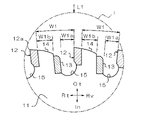
- FIG. 2 is an enlarged view showing a range surrounded by the alternate long and short dash line i in FIG.
- the cutting edge piece 12 is a substantially rectangular piece (chip) and is made of a material for a cutting tool.
- This material is, for example, cemented carbide, diamond sintered body (polycrystal line diamond, Poly Crystalline Diamond, PCD), CBN sintered body (cubic boron nitride, Cubic Boron Nitride), cermet, ceramics. And metal composite material) and sirmetal (registered trademark) (a material located between ceramics and cemented carbide).
- a cutting edge 12a is formed at a corner where the rotation side of the tip saw indicated by the arrow Rt of the cutting edge piece 12 and the outside in the radial direction intersect.
- the cutting edge 12a extends from the front surface 12A of the cutting edge piece 12 to the back surface 12B in the thickness direction (see FIG. 3).
- the cutting edge piece 12 is configured to be able to cut the work material by the cutting edge 12a.
- the support piece 13 is a substantially rectangular small piece (chip) like the cutting edge piece 12, and is made of a wear-resistant material.
- a wear-resistant material For example, cemented carbide.
- the support piece 13 may be made of the same material as the cutting edge piece 12, or may be made of a material different from that of the cutting edge piece 12.
- the manufacturing cost of the tip saw 10 can be reduced by reducing the material cost of the support piece 13 from the material cost of the cutting edge piece 12.
- a typical cemented carbide is obtained by mixing tungsten carbide (WC, tungsten carbide) and cobalt (Co) which is a binder (binder) and sintering them, and titanium carbide as needed.
- WC tungsten carbide
- Co cobalt
- TiC tantalum carbide
- TaC tantalum carbide
- the cutting edge piece 12 is attached to the rotation side of the tip saw 10 indicated by the arrow Rt of the tooth portion 14, and the support piece 13 is attached to the reverse rotation side of the tip saw 10 indicated by the arrow Rv of the tooth portion 14. Therefore, the cutting edge piece 12 and the support piece 13 are arranged so as to sandwich the tooth portion 14 from both the rotation side and the reverse rotation side of the tip saw 10. As a result, the cutting edge piece 12 and the support piece 13 are alternately arranged one by one with a predetermined angle around the rotation center O of the tip saw 10. In the illustrated example, 60 cutting edge pieces 12 and 60 support pieces 13 are provided as in the tooth portion 14.
- the method of attaching the cutting edge piece 12 and the support piece 13 is not particularly limited, and examples thereof include brazing, soldering, and welding.
- FIG. 3 is a schematic end view showing a state seen from the arrow L1 in FIG.
- the cutting edge piece 12 is configured to be wider than the base metal 11.
- the thickness direction of the cutting edge piece 12 is the thickness direction of the tip saw 10 indicated by the arrow Fr and the arrow Bk.
- the surface 12A of the cutting edge piece 12 protrudes from the position of the surface 11A of the base metal 11 toward the surface side of the tip saw 10 indicated by the arrow Fr, and the back surface 12B of the cutting edge piece 12 is the arrow Bk from the position of the back surface 11B of the base metal 11. It protrudes toward the back surface side of the tip saw 10 shown by.
- the thickness D2 of the cutting edge piece 12 is larger than the thickness D1 of the base metal 11 (D2> D1).
- the thickness D2 of the cutting edge piece 12 is the distance from the surface 12A to the back surface 12B in the thickness direction
- the thickness D1 of the base metal 11 is the distance from the surface 11A to the back surface 11B in the thickness direction.
- the cutting edge piece 12 is configured to be able to cut the work material wider than the thickness D1 of the base metal 11.
- Both the tooth portion 14 and the recess 15 are a part of the base metal 11, and have the same thickness as or close to the same thickness as the thickness D1 of the base metal 11.
- the support piece 13 is configured to be wider than the base metal 11.
- the surface 13A of the support piece 13 projects toward the front surface of the tip saw from the position of the surface 11A of the base metal 11, and the back surface 13B of the support piece 13 projects toward the back surface side of the tip saw from the position of the back surface 11B of the base metal 11.
- the thickness D3 of the support piece 13 is larger than the thickness of the base metal 11 (D3> D1).
- the thickness D3 of the support piece 13 is the distance from the front surface 13A to the back surface 13B in the thickness direction.
- the support piece 13 has the same thickness as or close to the same thickness as the cutting edge piece 12.
- the support piece 13 is arranged between two cutting edge pieces 12 and 12 adjacent to each other in the circumferential direction.
- the base metal 11 is located on the outer periphery of the tip saw 10 between the cutting edge piece 12 and the support piece 13 adjacent to the rotating side of the tip saw 10 and between the cutting edge piece 12 and the adjacent support piece 13 on the reverse rotation side. It is exposed from. Therefore, when the tip saw 10 is viewed from the outer circumference, the portion between the cutting edge piece 12 and the support piece 13 next to the rotating side of the tip saw 10 and the support piece 13 next to the cutting edge piece 12 on the reverse rotation side of the tip saw 10 The thickness of the tip saw 10 in the thickness direction is smaller than the thickness of the cutting edge piece 12 and the support piece 13.
- the distance extending from the cutting edge piece 12 to the rotation side of the tip saw 10 in the circumferential direction with the thickness D1 of the base 11 is from the cutting edge piece 12 to the support piece 13 next to the rotation side of the tip saw 10.
- the distance extending from the cutting edge piece 12 to the reverse rotation side of the tip saw 10 in the circumferential direction with the thickness D1 of the base 11 is from the cutting edge piece 12 to the support piece 13 next to the reverse rotation side of the tip saw 10. ing.
- the distance from the cutting edge piece 12 to the supporting piece 13 adjacent to the rotating side of the tip saw 10 is W1a
- the distance from the cutting edge piece 12 to the supporting piece 13 adjacent to the rotating side of the tip saw 10 is W1b.
- the distance W1a and the distance W1b are shorter than the distance W1
- the sum of the distance W1a and the distance W1b is the tip saw 10 of the support piece 13.
- the distance is shorter than the distance W1 by the length in the circumferential direction (W1a ⁇ W1, W1b ⁇ W1, W1a + W1b ⁇ W1).
- the distance W1a is a distance extending from the cutting edge piece 12 to the rotation side of the tip saw 10 in the circumferential direction with the thickness D1 of the base metal 11, and the distance W1b is the reverse of the cutting edge piece 12 to the tip saw 10. It is a distance that extends to the rotation side in the circumferential direction with the thickness D1 of the base metal 11.
- the support pieces 13 are arranged so as to include at least a central position between two adjacent cutting edge pieces 12 and 12 or a position near the center position. This is the case where the support piece 13 is located in the center between the two adjacent cutting edge pieces 12 and 12, and the state where the entire support piece 13 is offset to either of the two adjacent cutting edge pieces 12 and 12. Including the case where a part of the support piece 13 is located at the center between the two adjacent cutting edge pieces 12, 12. In this case, both the distance W1a and the distance W1b are smaller than half of the distance W1 (W1a ⁇ 1/2 ⁇ W1, W1b ⁇ 1/2 ⁇ W1), and the variation between the distance W1a and the distance W1b is reduced. .. In other words, when the tip saw 10 is viewed from the outer circumference, the portion where the base metal 11 is exposed becomes smaller in the circumferential direction of the tip saw 10.
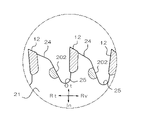
- FIG. 4 is a schematic plan view showing a state in which a hollow work material is cut by the tip saw of the first embodiment.
- FIG. 5 is an enlarged view showing a range surrounded by the alternate long and short dash line ii in FIG.
- the cutting edge piece 12 cuts into the work material P to form a cut groove Pc, and the inside of the cut groove Pc is formed.
- the width of the cutting groove Pc is maintained at the same width as the thickness D2 of the cutting edge piece 12, and when the support piece 13 is inserted into the cutting edge Pc, the width of the cutting groove Pc is maintained.
- the length is maintained at the same width as the thickness D3 of the support piece 13.
- the width length of the cut groove Pc is maintained at the same width as the thickness D1 of the base metal 11.
- the width length of the cutting groove Pc is larger than the thickness D1 of the base metal 11 and is the same width as the thickness D2 of the cutting edge piece 12. It is designed to be held in a width close to the same.
- the cutting edge 12a of the cutting edge piece 12 cuts the work material P. While cutting to form a cutting groove Pc, the cutting edge piece 12, the portion of the base metal 11 and the portion of the support piece 13 and the base metal 11 are sequentially inserted into the cutting groove Pc, and the work material P is formed. To disconnect.
- the support piece 13 is arranged between two adjacent cutting edge pieces 12 and 12, the thickness D3 of the support piece 13 is larger than the thickness of the base metal 11, and the thickness of the cutting edge piece 12 is large.
- the tip saw 10 is rotated to cut into the hollow work material P because it is the same as or close to D2
- the cutting edge 12a of the cutting edge piece 12 forms a cutting groove Pc in the work material P
- the cutting edge piece 12 and the support piece 13 are alternately and continuously inserted into the cutting edge Pc so that the width of the cutting edge Pc is the same as or the same as the thickness D2 of the cutting edge piece 12. Since the work material P is cut while keeping the width and length close to each other, the cut surface of the hollow work material P can be formed more clearly than the tip saw in which the support piece 13 does not exist.
- the distance extending from the cutting edge piece 12 to the rotation side of the tip saw 10 in the circumferential direction with the thickness D1 of the base metal 11 is the support next to the rotation side of the tip saw 10 from the cutting edge piece 12.
- the distance W1a between the cutting edge piece 13 and the cutting edge piece 12 to the reverse rotation side of the tip saw 10 in the circumferential direction with the thickness D1 of the base 11 is the distance extending from the cutting edge piece 12 to the reverse rotation side of the tip saw 10.
- the distance extending from the cutting edge piece 12 to the rotation side and the reverse rotation side of the tip saw 10 in the circumferential direction with the thickness D1 of the base metal 11 is shorter, so that the tip saw 10 covers the distance.
- the width of the cut groove Pc of the work material P can be widely held by the support piece 13.
- the support piece 13 is arranged so as to include at least a central position between two adjacent cutting edge pieces 12 and 12 or a position near the center position, the support piece 13 is adjacent to the cutting edge piece 12 on the rotation side of the tip saw 10.
- Distance W1a to the support piece 13 and the distance W1b from the cutting edge piece 12 to the adjacent support piece 13 on the reverse rotation side of the tip saw 10 are the distances between the two cutting edge pieces 12 and 12 adjacent to each other. Since it is smaller than half of W1 (W1a ⁇ 1/2 ⁇ W1, W1b ⁇ 1/2 ⁇ W1), when the work material P is cut by the tip saw 10, the cutting edge piece 12 and the support piece 13 are one. It is possible to reduce the variation in the timing of inserting the work material P into the cut groove Pc alternately one by one.
- FIG. 6 is a plan view showing the tip saw of the second embodiment.
- FIG. 7 is an enlarged view showing a range surrounded by the alternate long and short dash line iii of FIG.
- the support piece 13 is attached to the outside of the base metal 11, but in the tip saw 20 of the second embodiment, the support piece 23 has the base metal 21. It is provided inside.
- the inside of the base metal 21 means the inside in the radial direction from the outer peripheral edge of the base metal 21.
- the inside of the base metal 21 includes a radial inside from the outer peripheral edge of the tooth portion 24 and a radial inside from the outer peripheral edge of the recess 25.
- the same parts as those of the tip saw 10 of the first embodiment are designated by the same reference numerals, and the description thereof will be omitted.
- the cutting edge piece 12 of the second embodiment is the same as the cutting edge piece 12 of the first embodiment.
- the support piece 23 of the second embodiment is made of the same material as the support piece 13 of the first embodiment.
- the inside of the base metal 21 means the inside in the radial direction from the outer peripheral edge of the base metal 21.
- a notch 21n is formed in the base metal 21.
- the notches 21n are arranged radially inside the portion extending from the tooth portion 24 to the recess 25, respectively.
- the notch 21n is oval or elliptical when viewed from the surface 21A of the base metal 21, and penetrates from the surface 21A to the back surface 21B of the base metal 21.
- the support piece 23 is fitted in the notch 21n and has the same planar shape as the notch 21n. In other words, the support piece 23 is oval or oval.
- the notch 21n is formed at the outer edge portion of the base metal 21, it may be an opening or a through hole provided radially inside the outer edge portion of the base metal 21.
- FIG. 8 is a schematic end view showing a state seen from the arrow L2 in FIG. 7.
- the support piece 23 is arranged between two adjacent cutting edge pieces 12 and 12 at a position offset to the cutting edge piece 12 on the reverse rotation side of the tip saw 20.
- the portion is located at the center between the two cutting edge pieces 12 and 12 adjacent to each other, and the other portion extends so as to overlap the cutting edge piece 12 on the reverse rotation side of the tip saw 20 in the circumferential direction.
- the base metal 21, the support piece 23, and the cutting edge piece 12 of the second embodiment have the same thicknesses D1, D3, and D2 as the base metal 11, the support piece 13, and the cutting edge piece 12 of the first embodiment. Each has.
- the support piece 23 and the adjacent cutting edge piece 12 on the reverse rotation side thereof are arranged adjacent to each other in the circumferential direction, and are continuously arranged with the same thickness or a thickness close to the same.
- the surface 23A of the support piece 23 and the surface 12A of the cutting edge piece 12 adjacent to the reverse rotation side thereof are continuous without a step in the circumferential direction, and the back surface 23B of the support piece 23 and the reverse rotation side thereof. It is continuous with the back surface 12B of the adjacent cutting edge piece 12 without a step in the circumferential direction.
- the portion of the base metal 21 having the thickness D1 extends from the cutting edge piece 12 to the reverse rotation side of the tip saw 20, but from the cutting edge piece 12. It does not extend to the rotating side of the tip saw 20.
- the distance in the circumferential direction of the portion of the base metal 21 provided with the thickness D1 is the distance W2b from the cutting edge piece 12 to the adjacent support piece 23 on the reverse rotation side of the tip saw 20.
- the portion of the base metal 21 having the thickness D1 is only the distance W2b. Therefore, the tip saw 20 can make the portion of the thickness D1 of the base metal 21 exposed from the outer periphery of the tip saw 20 smaller than that of the tip saw 10 of the first embodiment.
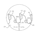
- FIG. 9 is a schematic plan view showing a state in which a hollow work material is cut by the tip saw of the second embodiment.
- FIG. 10 is an enlarged view showing a range surrounded by the alternate long and short dash line iv of FIG.
- the support piece 23 is formed in the cutting groove Pc of the work material P formed by the cutting edge 12a of the cutting edge piece 12. Is inserted, the width of the cutting groove Pc is maintained at the same width as the thickness D3 of the support piece 23, that is, the same width as or close to the thickness D2 of the cutting edge piece 12.
- the cutting edge 12a of the cutting edge piece 12 cuts the work material P. While forming the cutting groove Pc, the cutting edge piece 12, the portion of the base metal 21, and the support piece 23 are sequentially inserted into the cutting groove Pc to cut the work material P.
- the support piece 23 is arranged inside the base metal 21, the support piece 23 is used as compared with the tip saw 10 of the first embodiment in which the support piece 13 is attached to the outside of the tooth portion 14. Since the recess 25 of the tip saw 20 is not narrowed, it is possible to prevent deterioration of the chip discharge property of the tip saw 20.
- the support piece 23 and the cutting edge piece 12 adjacent to the tip saw 20 on the reverse rotation side are overlapped in the circumferential direction, and the support piece 23 and the tip saw 20 are viewed from the outer periphery of the tip saw 20. Since the adjacent cutting edge piece 12 on the reverse rotation side is arranged adjacent to each other, the support piece 23 and the adjacent cutting edge piece 12 on the reverse rotation side of the tip saw 20 are continuous with the same thickness or a thickness close to the same. Therefore, the width of the cut groove Pc of the work material P can be held wider than that of the chip sea 10 of the first embodiment for a long time.
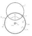
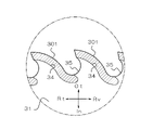
- FIG. 11 is a plan view showing the tip saw of the third embodiment.
- FIG. 12 is an enlarged view showing a range surrounded by the alternate long and short dash line v in FIG.
- the tip saw 10 of the first embodiment and the tip saw 20 of the second embodiment are provided with support pieces 13 and 23 between two cutting edge pieces 12 and 12 adjacent to each other.
- the tip saw 30 of the third embodiment is not provided with a support piece, and the cutting edge piece 32 extends to the reverse rotation side of the tip saw 30.
- the same parts as those of the tip saw 10 of the first embodiment are designated by the same reference numerals, and the description thereof will be omitted.
- the cutting edge piece 32 of the third embodiment is made of the same material as the cutting edge piece 12 of the first embodiment.
- the cutting edge piece 32 of the third embodiment has an elongated shape, and is provided with a cutting edge 32a at the end of the tip saw 30 on the rotation side.
- the cutting edge piece 32 is attached to the radial outer side of the tooth portion 34, and extends diagonally from the cutting edge 32a on the rotating side to the counter-rotating side of the tip saw 30 along the outer peripheral edge of the tooth portion 34.
- the cutting edge piece 32 covers the entire outer peripheral edge of the tooth portion 34.
- the method of attaching the cutting edge piece 32 to the tooth portion 34 is not particularly limited, and examples thereof include brazing, soldering, and welding.
- the cutting edge piece 32 has a cutting edge portion 32x and a supporting portion 32y.
- the cutting edge portion 32x is a portion of the cutting edge piece 32 on the rotation side of the tip saw 30, and includes the cutting edge 32a.
- the support portion 32y is a portion of the cutting edge piece 32 on the reverse rotation side of the tip saw 30.
- the cutting edge portion 32x and the support portion 32y have the same thickness D2.
- the cutting edge piece 32 forms a cutting groove Pc in the work material P by the cutting edge 32a of the cutting edge portion 32x, and then the width length of the cutting groove Pc is the same as the thickness D2 of the cutting edge piece 32 by the supporting portion 32y. It can be held in.
- FIG. 13 is an end view showing a state in which FIG. 12 is viewed from the arrow L3.
- a part of the cutting edge piece 32 overlaps with the adjacent cutting edge piece 32 on the reverse rotation side of the tip saw 30 in the circumferential direction.
- the two adjacent cutting edge pieces 32, 32 partially overlap in the circumferential direction.
- the supporting portion 32y of one cutting edge piece 32 overlaps the cutting edge portion 32x of the other cutting edge piece 32 in the circumferential direction.
- the cutting edge pieces 32 are arranged at a predetermined angle around the center of rotation O so that some of them overlap in the circumferential direction, and surround the base metal 31 without a gap in the circumferential direction.
- the two adjacent cutting edge pieces 32, 32 are arranged adjacent to each other without a gap in the circumferential direction, and one cutting edge piece 32 to the other.
- the cutting edge piece 32 of the above is continuous with the same thickness D2.
- the surface 32A of one cutting edge piece 32 and the surface 32A of the other cutting edge piece 32 are continuous in the circumferential direction without a step, and one of them.
- the back surface 32B of the cutting edge piece 32 and the back surface 32B of the other cutting edge piece 32 are continuous in the circumferential direction without a step.
- the cutting edge piece 32 can be continuously inserted into the cutting groove P of the work material P without any gap.
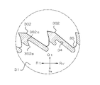
- FIG. 14 is a schematic plan view showing a state in which a hollow work material is cut by the tip saw of the third embodiment.
- FIG. 15 is an enlarged view showing a range surrounded by the alternate long and short dash line vi of FIG.
- the cutting edge piece 32 is inserted.
- the width of the cutting groove Pc is maintained at the same width as the thickness D2 of the cutting edge piece 32.
- the cutting edge 32a of the cutting edge piece 32 cuts the work material P. While forming the cutting groove Pc, the cutting edge pieces 32 are continuously inserted into the cutting groove Pc without any gap to cut the work material P.
- the tip saw 30 is not provided with the support pieces 13 and 23
- the tip saws of the first embodiment and the second embodiment provided with both the cutting edge piece 12 and the support pieces 13 and 23.
- the number of parts can be reduced and the manufacturing cost can be reduced.
- the cutting edge piece 32 extends to the reverse rotation side of the tip saw 30, and the cutting edge pieces 32 are partially overlapped in the circumferential direction with the two adjacent cutting edge pieces 32, 32.
- a clean cut surface can be obtained from the tipped saws 10 and 20 of the second embodiment.
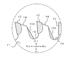
- the support piece 13 of the first embodiment has a rectangular shape with rounded corners (see FIG. 2)
- the support piece 101 may have a rectangular shape with sharp corners (see FIG. 16)
- the support piece 102 has a tooth portion. It may have a substantially triangular shape having a hypotenuse extending linearly from the radial outer end (protruding end) of 14 to the inner bottom of the recess 15 (see FIG. 17).
- the support piece 23 in the second embodiment is arranged radially inside the portion extending from the tooth portion 24 to the recess 25 (see FIG. 7), the support piece 23 is arranged radially inside the tooth portion 24 (the root of the tooth portion 24). It may be arranged in the radial direction of the recess 25.
- the support pieces 201, 202, 203, and 204 may be arranged on the portion of the tooth portion 24 on the reverse rotation side of the tip saw 20 (see FIGS. 18 to 21).
- the support piece 23 in the second embodiment is oval or elliptical (see FIG. 7), but the planar shape of the support piece 23 is not particularly limited, and may be circular, for example, pentagonal, hexagonal, or octagonal. It may be a polygon such as a square. Further, the support piece 201 may be rectangular (see FIG. 18), the support piece 202 may be semi-cylindrical (see FIG. 19), the support piece 203 may be semi-circular (see FIG. 20), and the support piece 204 may be. May be crescent-shaped (see FIG. 21).
- the cutting edge piece 32 in the third embodiment has a linear shape extending diagonally from the rotation side of the tip saw 30 to the reverse rotation side (see FIG. 12), but the cutting edge piece 301 may have a curved shape (see FIG. 22). ..
- the cutting edge piece 32 in the third embodiment has a flat portion in the radial direction, that is, a portion in contact with the tooth portion 34 (see FIG. 12), but the cutting edge piece 32 and the tooth portion 34 of the cutting edge pieces 302, 303, 304.
- the contacting portion is preferably uneven (see FIGS. 23 to 25).
- the cutting edge pieces 302, 303, and 304 can be made difficult to come off from the tooth portion 34.
- the cutting edge piece 302 is formed with a convex portion 302p protruding in the extending direction of the cutting edge piece 302 and a concave recess 302q (see FIG. 23).
- the cutting edge piece 303 is formed with a convex portion 303p protruding and a concave recess 303q in a direction intersecting the extending direction of the cutting edge piece 303, that is, in a direction in contact with the tooth portion 34 (see FIG. 24).
- the cutting edge piece 304 is formed with dovetail grooves 304q and 304q recessed in the direction in contact with the tooth portion 34 (see FIG. 25).
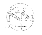
- the cutting edge piece 32 in the third embodiment is entirely composed of one material, but the cutting edge piece 32 has a cutting edge portion 32x on the rotation side of the tip saw 30 and a support portion 32y on the reverse rotation side of the tip saw 30. It may be composed of different materials.
- the cutting edge portion 305x is made of the same cutting tool material as the cutting edge piece 12 of the first embodiment, and the supporting portion 305y is the material of the first embodiment. It is made of the same wear-resistant material as the support piece 13. As a result, the manufacturing cost of the tip saw can be reduced.
- the two adjacent cutting edge pieces 32, 32 in the third embodiment are arranged so as to partially overlap each other in the circumferential direction
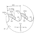
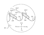
- the two adjacent cutting edge pieces 306, 306, 307, 307 are circular. They may be arranged so as not to overlap in the circumferential direction (see FIGS. 27 and 28).
- the cutting edge pieces 306 are at least the distance in the circumferential direction. It may extend along the outer peripheral edge of the tooth portion 34 to a position corresponding to half of W3 (1/2 / W3).
- the cutting edge piece 307 may be made of different materials from the cutting edge portion 307x on the rotation side of the tip saw 30 and the support portion 307y on the reverse rotation side of the tip saw 30. That is, the cutting edge portion 307x of the cutting edge piece 307 is made of the same cutting tool material as the cutting edge piece 12 of the first embodiment, and the supporting portion 307y of the cutting edge piece 307 is the supporting piece 13 of the first embodiment. It is composed of the same wear resistant material as. As a result, the manufacturing cost of the tip saw can be reduced.
- 1,2,3,10,20,30 ... Tipped saw 1a, 12,32,301,302,303,304,305,306,307 ...
- Cutting edge piece 1A, 3A, 11,21,31 ...
- Base metal 2a, 3a ... 1st cutting edge piece, 2b, 3b ... 2nd cutting edge piece, 2s, 3s ... groove, 3c ... 3rd cutting edge piece, 3h ... long hole, 11a ... mounting hole, 11A, 12A, 13A, 21A, 23A, 32A ... front surface, 11B, 12B, 13B, 21B, 23B, 32B ... back surface, 12a, 32a, 306a ... cutting edge, 13,23,101,102,201,202,203,204 ...
Landscapes
- Life Sciences & Earth Sciences (AREA)
- Engineering & Computer Science (AREA)
- Mechanical Engineering (AREA)
- Wood Science & Technology (AREA)
- Forests & Forestry (AREA)
- Sawing (AREA)
- Cutting Tools, Boring Holders, And Turrets (AREA)
- Nonmetal Cutting Devices (AREA)
Priority Applications (2)
| Application Number | Priority Date | Filing Date | Title |
|---|---|---|---|
| US18/000,182 US20230211428A1 (en) | 2020-12-22 | 2021-02-22 | Tip saw |
| US19/227,420 US20250296165A1 (en) | 2020-12-22 | 2025-06-03 | Tip saw |
Applications Claiming Priority (2)
| Application Number | Priority Date | Filing Date | Title |
|---|---|---|---|
| JP2020-212855 | 2020-12-22 | ||
| JP2020212855A JP7589980B2 (ja) | 2020-12-22 | 2020-12-22 | チップソー |
Related Child Applications (2)
| Application Number | Title | Priority Date | Filing Date |
|---|---|---|---|
| US18/000,182 A-371-Of-International US20230211428A1 (en) | 2020-12-22 | 2021-02-22 | Tip saw |
| US19/227,420 Division US20250296165A1 (en) | 2020-12-22 | 2025-06-03 | Tip saw |
Publications (1)
| Publication Number | Publication Date |
|---|---|
| WO2022137576A1 true WO2022137576A1 (ja) | 2022-06-30 |
Family
ID=82158016
Family Applications (1)
| Application Number | Title | Priority Date | Filing Date |
|---|---|---|---|
| PCT/JP2021/006559 Ceased WO2022137576A1 (ja) | 2020-12-22 | 2021-02-22 | チップソー |
Country Status (3)
| Country | Link |
|---|---|
| US (2) | US20230211428A1 (https=) |
| JP (2) | JP7589980B2 (https=) |
| WO (1) | WO2022137576A1 (https=) |
Cited By (1)
| Publication number | Priority date | Publication date | Assignee | Title |
|---|---|---|---|---|
| US20240181546A1 (en) * | 2022-09-01 | 2024-06-06 | Milwaukee Electric Tool Corporation | Reciprocating Saw Blade Having Teeth Formed of a Cemented Ceramic Material Welded to the Body of the Blade |
Citations (8)
| Publication number | Priority date | Publication date | Assignee | Title |
|---|---|---|---|---|
| US3576200A (en) * | 1969-02-26 | 1971-04-27 | Heinemann Saw Corp | Circular saw |
| US4173914A (en) * | 1977-09-06 | 1979-11-13 | Vollmer Of America Corporation | Cutting teeth for circular saw blades |
| US5743163A (en) * | 1995-05-23 | 1998-04-28 | Lavinder; Edward E. | Clean cutting circular saw blade |
| JP2001009633A (ja) * | 1999-07-01 | 2001-01-16 | Motoyuki:Kk | チップソー |
| JP2006305863A (ja) * | 2005-04-28 | 2006-11-09 | Tenryu Saw Mfg Co Ltd | 丸鋸 |
| JP2007144608A (ja) * | 2005-11-02 | 2007-06-14 | Tenryu Saw Mfg Co Ltd | 回転鋸 |
| JP2009220548A (ja) * | 2008-03-15 | 2009-10-01 | Nihon Kenki Kk | 回転鋸 |
| WO2014065069A1 (ja) * | 2012-10-22 | 2014-05-01 | 兼房株式会社 | チップソー |
Family Cites Families (29)
| Publication number | Priority date | Publication date | Assignee | Title |
|---|---|---|---|---|
| US192526A (en) * | 1877-06-26 | Improvement in circular saws | ||
| US646373A (en) * | 1898-07-29 | 1900-03-27 | Dewey Phillips | Saw. |
| US1810823A (en) * | 1930-06-13 | 1931-06-16 | Henry Disston & Sons Inc | Circular saw |
| US2763258A (en) * | 1954-07-01 | 1956-09-18 | Hughes Blades Inc | Construction of circular saws |
| NL112204C (https=) * | 1959-04-20 | |||
| US2990828A (en) * | 1960-09-19 | 1961-07-04 | Super Cut | Rotary segmental saw with rim rigidifying and silencing means |
| US3036567A (en) * | 1961-07-19 | 1962-05-29 | Super Cut | Rotary stone cutting saws with peripheral diamond teeth and intervening sweeper elements |
| US3133533A (en) * | 1963-03-15 | 1964-05-19 | Milton G Sprague | Circular saw |
| US3196584A (en) * | 1963-06-28 | 1965-07-27 | Tatko John | Abrasive wheels and segmented diamond wheels |
| US3513821A (en) * | 1968-02-05 | 1970-05-26 | Ferro Corp | Abrasive cut-off wheel |
| US3763601A (en) * | 1972-05-15 | 1973-10-09 | Ferro Corp | Diamond abrasive cut-off wheel |
| US3820233A (en) * | 1972-07-20 | 1974-06-28 | J Baker | Precision cutting tool |
| JPS603523B2 (ja) * | 1977-12-29 | 1985-01-29 | 三菱マテリアル株式会社 | リ−ド線切断用丸刃工具 |
| US4516560A (en) * | 1982-07-29 | 1985-05-14 | Federal-Mogul Corporation | Abrasive cutting wheel and method of cutting abradable material |
| US4462382A (en) * | 1983-06-30 | 1984-07-31 | Baron Frank C | Circular saw for cutting green concrete and asphalt |
| US4627322A (en) * | 1985-09-17 | 1986-12-09 | Lebever Co. | Circular saw blade assembly |
| JPH05285722A (ja) * | 1992-04-07 | 1993-11-02 | Kimura Shokai:Kk | 歯先にダイヤモンドと超硬合金 を併用したチップソー |
| US5285768A (en) * | 1992-08-28 | 1994-02-15 | Sanders Saws, Inc. | Two tier groove cutting circular saw blade with anti-undercut features |
| JPH0839346A (ja) * | 1994-07-27 | 1996-02-13 | Osaka Diamond Ind Co Ltd | サーキュラソー |
| US6203416B1 (en) * | 1998-09-10 | 2001-03-20 | Atock Co., Ltd. | Outer-diameter blade, inner-diameter blade, core drill and processing machines using same ones |
| KR100440869B1 (ko) * | 2001-02-19 | 2004-07-19 | 이화다이아몬드공업 주식회사 | 절단용 톱판 |
| KR100440870B1 (ko) * | 2001-02-19 | 2004-07-19 | 이화다이아몬드공업 주식회사 | 언더컷 방지용 팁을 이용한 다이아몬드 소우 블레이드 |
| US6845767B2 (en) * | 2002-05-14 | 2005-01-25 | Diamant Boart, Inc. | Segmented diamond blade with undercut protection |
| JP2005124407A (ja) | 2003-10-21 | 2005-05-19 | Katsuji Moriyama | 草刈用チップソー |
| RU2004101704A (ru) * | 2004-01-20 | 2005-06-27 | Михаил Андреевич Бранфилев (RU) | Круглая строгальная пила |
| US20080017009A1 (en) * | 2004-02-13 | 2008-01-24 | Setliff David D | Reversible circular saw blade |
| DE102004031600B4 (de) * | 2004-06-30 | 2006-04-20 | Hilti Ag | Werkzeug zur Bearbeitung eines mineralischen Untergrundes mit einem Ultraschall-Werkzeuggerät |
| US9517571B2 (en) | 2010-01-26 | 2016-12-13 | Hyde Tools, Inc. | Circular cutting blade |
| PE20231956A1 (es) * | 2016-05-27 | 2023-12-06 | Joy Global Underground Mining Llc | Dispositivo de corte con elemento de corte con seccion decreciente |
-
2020
- 2020-12-22 JP JP2020212855A patent/JP7589980B2/ja active Active
-
2021
- 2021-02-22 WO PCT/JP2021/006559 patent/WO2022137576A1/ja not_active Ceased
- 2021-02-22 US US18/000,182 patent/US20230211428A1/en not_active Abandoned
-
2024
- 2024-09-10 JP JP2024156844A patent/JP7722746B2/ja active Active
-
2025
- 2025-06-03 US US19/227,420 patent/US20250296165A1/en active Pending
Patent Citations (8)
| Publication number | Priority date | Publication date | Assignee | Title |
|---|---|---|---|---|
| US3576200A (en) * | 1969-02-26 | 1971-04-27 | Heinemann Saw Corp | Circular saw |
| US4173914A (en) * | 1977-09-06 | 1979-11-13 | Vollmer Of America Corporation | Cutting teeth for circular saw blades |
| US5743163A (en) * | 1995-05-23 | 1998-04-28 | Lavinder; Edward E. | Clean cutting circular saw blade |
| JP2001009633A (ja) * | 1999-07-01 | 2001-01-16 | Motoyuki:Kk | チップソー |
| JP2006305863A (ja) * | 2005-04-28 | 2006-11-09 | Tenryu Saw Mfg Co Ltd | 丸鋸 |
| JP2007144608A (ja) * | 2005-11-02 | 2007-06-14 | Tenryu Saw Mfg Co Ltd | 回転鋸 |
| JP2009220548A (ja) * | 2008-03-15 | 2009-10-01 | Nihon Kenki Kk | 回転鋸 |
| WO2014065069A1 (ja) * | 2012-10-22 | 2014-05-01 | 兼房株式会社 | チップソー |
Cited By (1)
| Publication number | Priority date | Publication date | Assignee | Title |
|---|---|---|---|---|
| US20240181546A1 (en) * | 2022-09-01 | 2024-06-06 | Milwaukee Electric Tool Corporation | Reciprocating Saw Blade Having Teeth Formed of a Cemented Ceramic Material Welded to the Body of the Blade |
Also Published As
| Publication number | Publication date |
|---|---|
| JP2024161296A (ja) | 2024-11-15 |
| JP2022099094A (ja) | 2022-07-04 |
| JP7589980B2 (ja) | 2024-11-26 |
| JP7722746B2 (ja) | 2025-08-13 |
| US20250296165A1 (en) | 2025-09-25 |
| US20230211428A1 (en) | 2023-07-06 |
Similar Documents
| Publication | Publication Date | Title |
|---|---|---|
| JP5221342B2 (ja) | 特にクランク軸加工のためのカッティングインサート | |
| CN100404179C (zh) | 切削元件和装备有至少一个切削元件的刀具 | |
| JPH0753853Y2 (ja) | ボールエンドミル | |
| JP4763855B2 (ja) | 切削インサート及び切削工具、並びにそれを用いた被削材の切削方法 | |
| JP5790765B2 (ja) | 切削インサートおよび回転切削工具 | |
| CN106660145B (zh) | 切削刀片及刀头更换式切削刀具 | |
| CN102387886B (zh) | 多刀片钻头头部及其钻头 | |
| JPH07276130A (ja) | 切削チップ特に転回式切削チップ | |
| JP2019042816A (ja) | 切削インサート及び切削工具 | |
| JP7722746B2 (ja) | チップソー | |
| CN112334258B (zh) | 双面切向铣削刀片 | |
| JPH0512029U (ja) | ボールエンドミル | |
| JP2008213117A (ja) | 回転鋸 | |
| CN101227993A (zh) | 切削嵌件 | |
| JPWO2014021250A1 (ja) | 切削インサート、切削工具および切削加工物の製造方法 | |
| WO2019026697A1 (ja) | 切削インサート、切削工具及び切削加工物の製造方法 | |
| JP4624755B2 (ja) | 歯切り用回転切削工具 | |
| JP3033166B2 (ja) | 回転工具 | |
| JPWO2019167866A1 (ja) | 切削インサート、切削工具及び切削加工物の製造方法 | |
| JP2000254822A (ja) | チップソー | |
| JP2009061521A (ja) | スローアウェイチップとそれを用いた回転切削工具 | |
| JP7795584B2 (ja) | 切削工具、切削工具の製造方法及びチップの製造方法 | |
| JP2008213093A (ja) | チップソー、その製造方法及びチップソー用チップ | |
| JP2014124719A (ja) | 切削インサート、切削工具および切削加工物の製造方法 | |
| JP3206035U (ja) | チップソー |
Legal Events
| Date | Code | Title | Description |
|---|---|---|---|
| 121 | Ep: the epo has been informed by wipo that ep was designated in this application |
Ref document number: 21909738 Country of ref document: EP Kind code of ref document: A1 |
|
| NENP | Non-entry into the national phase |
Ref country code: DE |
|
| 122 | Ep: pct application non-entry in european phase |
Ref document number: 21909738 Country of ref document: EP Kind code of ref document: A1 |