WO2022137282A1 - 無線通信システム、無線通信方法、送信装置、及び受信装置 - Google Patents
無線通信システム、無線通信方法、送信装置、及び受信装置 Download PDFInfo
- Publication number
- WO2022137282A1 WO2022137282A1 PCT/JP2020/047669 JP2020047669W WO2022137282A1 WO 2022137282 A1 WO2022137282 A1 WO 2022137282A1 JP 2020047669 W JP2020047669 W JP 2020047669W WO 2022137282 A1 WO2022137282 A1 WO 2022137282A1
- Authority
- WO
- WIPO (PCT)
- Prior art keywords
- signals
- unit
- frequency channels
- wireless communication
- predetermined power
- Prior art date
- Legal status (The legal status is an assumption and is not a legal conclusion. Google has not performed a legal analysis and makes no representation as to the accuracy of the status listed.)
- Ceased
Links
Images



Classifications
-
- H—ELECTRICITY
- H04—ELECTRIC COMMUNICATION TECHNIQUE
- H04L—TRANSMISSION OF DIGITAL INFORMATION, e.g. TELEGRAPHIC COMMUNICATION
- H04L5/00—Arrangements affording multiple use of the transmission path
- H04L5/003—Arrangements for allocating sub-channels of the transmission path
-
- H—ELECTRICITY
- H04—ELECTRIC COMMUNICATION TECHNIQUE
- H04J—MULTIPLEX COMMUNICATION
- H04J1/00—Frequency-division multiplex systems
- H04J1/02—Details
- H04J1/08—Arrangements for combining channels
-
- H—ELECTRICITY
- H04—ELECTRIC COMMUNICATION TECHNIQUE
- H04B—TRANSMISSION
- H04B7/00—Radio transmission systems, i.e. using radiation field
- H04B7/02—Diversity systems; Multi-antenna system, i.e. transmission or reception using multiple antennas
- H04B7/04—Diversity systems; Multi-antenna system, i.e. transmission or reception using multiple antennas using two or more spaced independent antennas
- H04B7/04013—Intelligent reflective surfaces
-
- H—ELECTRICITY
- H04—ELECTRIC COMMUNICATION TECHNIQUE
- H04B—TRANSMISSION
- H04B7/00—Radio transmission systems, i.e. using radiation field
- H04B7/02—Diversity systems; Multi-antenna system, i.e. transmission or reception using multiple antennas
- H04B7/10—Polarisation diversity; Directional diversity
-
- H—ELECTRICITY
- H04—ELECTRIC COMMUNICATION TECHNIQUE
- H04J—MULTIPLEX COMMUNICATION
- H04J11/00—Orthogonal multiplex systems, e.g. using WALSH codes
- H04J2011/0003—Combination with other multiplexing techniques
- H04J2011/0009—Combination with other multiplexing techniques with FDM/FDMA
-
- H—ELECTRICITY
- H04—ELECTRIC COMMUNICATION TECHNIQUE
- H04L—TRANSMISSION OF DIGITAL INFORMATION, e.g. TELEGRAPHIC COMMUNICATION
- H04L5/00—Arrangements affording multiple use of the transmission path
- H04L5/02—Channels characterised by the type of signal
- H04L5/04—Channels characterised by the type of signal the signals being represented by different amplitudes or polarities, e.g. quadriplex
Definitions
- the present invention relates to a wireless communication system, a wireless communication method, a transmitting device, and a receiving device.
- Massive MIMO Multiple Input Multiple Output
- non-orthogonal multiple access non-orthogonal multiple access
- NOMA Non-Orthogonal Multiple Access
- NOMA is the same by intentionally non-orthogonally multiplexing a plurality of user signals in the power axis direction when the base station transmits signals to a plurality of user terminals (UEs) on the downlink.
- This is a multiple access method in which a plurality of user signals are multiplexed and transmitted on the wireless resource of the above (see, for example, Non-Patent Document 1).
- Non-Patent Document 1 is a technique for multiplexing signals transmitted from one base station to a plurality of user terminals located in different directions and distances, and is the same radio such as fixed micro communication. It was not applicable to multiplexing frequency channels in the interval.
- the present invention has been made in view of the above-mentioned problems, and is a wireless communication system, a wireless communication method, and a transmission device capable of multiplexing and transmitting more signals than the number of frequency channels even in the same wireless section. , And a receiver is intended to be provided.
- the wireless communication system is a wireless communication system in which a transmitting device and a receiving device perform wireless communication using n (n ⁇ 2) frequency channels, and the transmitting device has n + 1 signals. Is converted into n predetermined power signals whose C / N is set to a predetermined value and divided signals whose C / N is divided into n by setting 1 / n of each predetermined value, and the above-mentioned conversion.
- a superimposition unit that superimposes n predetermined power signals and n divided signals converted by the unit non-orthogonally so as to be n multiplex signals for the n frequency channels, and the superimposition unit superimposes each other.
- It has a transmission unit that simultaneously transmits the n multiple signals transmitted by the n frequency channels, and the receiving device receives the n multiplex signals transmitted by the n frequency channels. And, the demodulator that demolishes n predetermined power signals from the n multiplex signals received by the receiving unit and the n predetermined power signals demolished by the demodulator are duplicated to obtain n replica signals.
- n + 1 signals are transmitted to C.
- the transmitting device is a transmitting device that performs wireless communication with a receiving device using n (n ⁇ 2) frequency channels, and transmits n + 1 signals to C / N.
- a conversion unit that converts n predetermined power signals defined by a predetermined value, a divided signal in which C / N is divided into n by setting 1 / n of each predetermined value, and n conversion units converted by the conversion unit.
- the receiving device is a receiving device that wirelessly communicates with a transmitting device using n (n ⁇ 2) frequency channels, and the receiving device has n transmitted by the n frequency channels.
- the receiving unit that receives the multiplex signal, the demodulator that demolishes n predetermined power signals from the n multiplex signals received by the receiving unit, and the n predetermined power signals that the demodulator has demolished are duplicated.
- the replica creation unit that creates n replica signals and the n replica signals created by the replica creation unit are each subtracted from each of the n multiplex signals received by the reception unit, and after n subtractions. It is characterized by having a subtraction unit for calculating a signal and a synthesis unit for synthesizing n post-subtraction signals calculated by the subtraction unit.
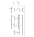
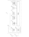
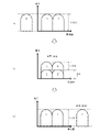
- FIG. 1 shows the configuration example of the wireless communication system which concerns on one Embodiment. It is a functional block diagram which illustrates the function which the transmission station which concerns on one Embodiment has. It is a functional block diagram which illustrates the function which the receiving station which concerns on one Embodiment has.
- (A) is a figure which shows n + 1 transmission signals transmitted by a transmission station.
- (B) is a figure which shows the transmission signal which a transmission station converts and superimposes.
- C is a diagram showing n + 1 signals received and acquired by the receiving station.
- A) is a figure which shows n + 1 transmission signals transmitted by a transmission station.
- (B) is a figure which shows the transmission signal which a transmission station converts and superimposes.
- (C) is a diagram showing n + 1 signals received and acquired by the receiving station. It is a figure which shows the structure of the modification of the wireless communication system which concerns on one Embodiment. It is a figure which shows the hardware configuration example of the transmission station which concerns on one Embodiment.
- FIG. 1 is a diagram showing a configuration example of a wireless communication system 1 according to an embodiment.
- the wireless communication system 1 includes a transmitting station 2 and a receiving station 3, and the transmitting station 2 and the receiving station 3 are configured to perform wireless communication such as fixed micro communication.
- the transmitting station 2 transmits a signal to the receiving station 3 by a non-orthogonal multiple access (NOMA) using n (n ⁇ 2) frequency channels. It is assumed that the n frequency channels are frequency channels in which at least one of the plane of polarization and the frequency is different from each other.
- NOMA non-orthogonal multiple access
- the transmitting station 2 and the receiving station 3 are wireless communication devices that transmit and receive signals to each other.
- a wireless communication system is taken as an example in which the transmitting station 2 functions as a transmitting device and the receiving station 3 functions as a receiving device. 1 will be described.
- FIG. 2 is a functional block diagram illustrating the functions of the transmitting station 2 according to the embodiment.
- the transmitting station 2 has, for example, a control unit 20, a modulation unit 22, a NOMA processing unit 24, a communication unit 26, and a plurality of antennas 28.
- a case where the transmitting station 2 has a plurality of antennas 28 and performs MIMO transmission will be described as an example, but even if the transmitting station 2 has one antenna 28 and does not perform MIMO transmission. good.
- the control unit 20 controls each unit constituting the transmission station 2, generates n + 1 transmission signals for the receiving station 3, for example, and outputs the generated transmission signals to the modulation unit 22.
- the modulation unit 22 performs, for example, quadrature amplitude modulation (QAM) on n + 1 transmission signals generated by the control unit 20, and outputs the modulated transmission signal to the NOMA processing unit 24.
- QAM quadrature amplitude modulation
- the NOMA processing unit 24 has, for example, a conversion unit 240 and a superimposition unit 242, performs NOMA processing on n + 1 transmission signals modulated by the modulation unit 22, and outputs the NOMA-processed transmission signal to the communication unit 26. do.
- the conversion unit 240 uses n + 1 transmission signals as n predetermined power signals having a carrier-to-noise ratio (C / N) set to a predetermined value and n by setting C / N to 1 / n of a predetermined value. It is converted into a divided signal divided into pieces, and the converted transmission signal is output to the superimposing unit 242.
- C / N carrier-to-noise ratio
- the conversion unit 240 has n + 1 transmission signals and n (1st to nth) predetermined C / N as A. It is converted into a power signal and one (n + 1) divided signal obtained by dividing C / N into n pieces as (1 / n) A.
- the superimposing unit 242 superimposes and superimposes the n predetermined power signals converted by the conversion unit 240 and the n divided signals non-orthogonally so as to be n multiplex signals for n frequency channels.
- the n multiple signals are output to the communication unit 26.
- the superimposition unit 242 does not convert the n predetermined power signals output by the conversion unit 240 and one divided signal divided into n into n multiplex signals for n frequency channels. Superimpose orthogonally.
- the communication unit 26 has a transmission unit 260 and a reception unit 262, and transmits / receives radio signals via a plurality of antennas 28.
- the transmission unit 260 simultaneously transmits n multiple signals superimposed by, for example, the superimposition unit 242 by n frequency channels via a plurality of antennas 28.
- the receiving unit 262 receives, for example, a signal transmitted by the receiving station 3 via the plurality of antennas 28, and outputs the received signal to the control unit 20.
- FIG. 3 is a functional block diagram illustrating the functions of the receiving station 3 according to the embodiment.
- the receiving station 3 has, for example, a control unit 30, a plurality of antennas 31, a communication unit 32, a first demodulation unit 33, a replica creation unit 34, a subtraction unit 35, a synthesis unit 36, and a second demodulation unit.
- Has 37 a case where the receiving station 3 has a plurality of antennas 31 and performs MIMO transmission will be described as an example, but even if the receiving station 3 has one antenna 31 and does not perform MIMO transmission. good.
- the control unit 30 controls each unit constituting the receiving station 3 and performs predetermined processing on the transmission signal and the reception signal.
- the communication unit 32 has a reception unit 320 and a transmission unit 322, and transmits / receives radio signals via a plurality of antennas 31.
- the receiving unit 320 receives the n multiplex signals transmitted by the transmitting station 2 through, for example, n frequency channels via the plurality of antennas 31, and the received multiplex signals are sent to the first demodulation unit 33 and the subtraction unit 35. Output to.
- the transmission unit 322 transmits the signal processed by the control unit 30 in the direction corresponding to the control of the control unit 30 via the plurality of antennas 31.
- the first demodulation unit 33 demodulates n predetermined power signals from the n multiplex signals received by the reception unit 320, and creates n demodulated (1st to nth) predetermined power signals as a control unit 30 and a replica. Output to unit 34.
- the replica creation unit 34 duplicates each of the n predetermined power signals demodulated by the first demodulation unit 33 to create n replica signals, and outputs the created n replica signals to the subtraction unit 35. ..
- the subtraction unit 35 subtracts each of the n replica signals created by the replica creation unit 34 from each of the n multiplex signals received by the reception unit 320, and calculates the n subtracted signals. Then, the subtraction unit 35 outputs the calculated n subtracted signals to the synthesis unit 36.
- the synthesis unit 36 synthesizes n subtracted signals calculated by the subtraction unit 35, and outputs the combined signal to the second demodulation unit 37. For example, the synthesizing unit 36 restores one (n + 1) transmission signal from the divided signals divided into n by synthesizing the n subtracted signals calculated by the subtracting unit 35 as a combined signal. ..
- the second demodulation unit 37 demodulates the composite signal synthesized by the synthesis unit 36, and outputs the demodulated composite signal (that is, the n + 1th transmission signal) to the control unit 30.
- control unit 30 acquires n (1st to nth) predetermined power signals from the first demodulation unit 33, and one (n + 1) transmission signal divided into n is the second demodulation unit. It can be obtained from 37.
- the receiving station 3 may be configured so that the first demodulation unit 33 also has the function of the second demodulation unit 37.
- FIG. 4 is a diagram schematically showing a first example of a signal (radio wave) transmitted by the transmitting station 2 and received by the receiving station 3.
- FIG. 4B is a diagram showing a transmission signal converted and superimposed by the transmitting station 2.
- A be the C / N required to demodulate the transmission signals X, Y, and Z, respectively. That is, the transmitting station 2 allocates two predetermined power signals (transmission signals X and Y) whose C / N is defined as A to frequency channels having the same polarization and different frequencies.
- the transmitting station 2 sets the C / N of the transmission signals Z not assigned to the n (that is, two) frequency channels to 1 / n (that is, 1/2) of A, respectively, and sets the C / N to n (that is, two). ) Divided into signals. Then, the transmitting station 2 superimposes the divided n (that is, two) divided signals on the predetermined power signals (transmission signals X and Y) of the n (that is, two) frequency channels in a non-orthogonal manner. It is transmitted as n (that is, two) multiplex signals (FIG. 4 (b)). That is, the transmitting station 2 simultaneously transmits the multiplexed signal multiplexed in the non-orthogonal direction in the power axis direction to the receiving station 3 for the same radio resource.
- the receiving station 3 receives n (ie, two) multiplex signals assigned and transmitted by the transmitting station 2 to n (that is, two) frequency channels.
- the receiving station 3 demodulates n predetermined power signals from n multiplex signals, creates n replica signals, and subtracts them from each of the n multiplex signals (interference elimination processing due to power difference).
- the separated / extracted n (1 / n) A after subtraction signals are combined. That is, the receiving station 3 can restore the transmission signal Z whose C / N is A required for demodulation (FIG. 4 (c)).
- FIG. 5 is a diagram schematically showing a second example of a signal (radio wave) transmitted by the transmitting station 2 and received by the receiving station 3.
- FIG. 5B is a diagram showing a transmission signal converted and superimposed by the transmitting station 2.
- the transmitting station 2 allocates two predetermined power signals (transmission signals X and Y) whose C / N is defined as A to frequency channels having different planes of polarization.
- the transmitting station 2 sets the C / N of the transmission signals Z not assigned to the n (that is, two) frequency channels to 1 / n (that is, 1/2) of A, respectively, and sets the C / N to n (that is, two). ) Divided into signals. Then, the transmitting station 2 superimposes the divided n (that is, two) divided signals on the predetermined power signals (transmission signals X and Y) of the n (that is, two) frequency channels in a non-orthogonal manner. It is transmitted as n (that is, two) multiplex signals (FIG. 5 (b)). That is, the transmitting station 2 simultaneously transmits the multiplexed signal multiplexed in the non-orthogonal direction in the power axis direction to the receiving station 3 for the same radio resource.
- the receiving station 3 receives n (ie, two) multiplex signals assigned and transmitted by the transmitting station 2 to n (that is, two) frequency channels.
- the receiving station 3 demodulates n predetermined power signals from n multiplex signals, creates n replica signals, and subtracts them from each of the n multiplex signals (interference elimination processing due to power difference).
- the separated / extracted n (1 / n) A after subtraction signals are combined. That is, the receiving station 3 can restore the transmission signal Z whose C / N is A required for demodulation (FIG. 5 (c)).
- the receiving station 3 can simultaneously receive a signal larger than the number of channels.
- the transmitting station 2 has a larger number than the number of frequency channels so that the receiving station 3 can separate and extract the divided signal based on the power ratio (or power difference) between the predetermined power signal and the divided signal, and then synthesize and demodulate the divided signal.
- the transmission signal may be converted into a multiplex signal having the number of frequency channels, and the conversion method is not limited to the above-mentioned example.
- the wireless communication system 1 may use only one of vertically polarized waves and horizontally polarized waves, and may use frequency channels of both vertically polarized waves having a frequency f1 and horizontally polarized waves having a frequency f1. It may be used, or a frequency channel of vertically polarized waves having a frequency f1 and horizontally polarized waves having a frequency f2 may be used.
- the wireless communication system 1 has n predetermined power signals having C / N set to predetermined values and C / N having predetermined values for transmission signals larger than the number of frequency channels. It is converted into 1 / n and divided into n divided signals, and the converted n predetermined power signals and n divided signals are converted into n multiplex signals for n frequency channels. Since the signals are superimposed in a non-orthogonal manner, more signals than the number of frequency channels can be multiplexed and transmitted even in the same radio section, and the frequency utilization efficiency can be improved.
- FIG. 6 is a diagram showing a configuration of a modification (wireless communication system 1a) of the wireless communication system 1 according to the embodiment.
- the wireless communication system 1a includes a transmitting station 2, a relay station 4, a receiving station (first wireless communication device) 5-1 and a receiving station (second wireless communication device) 5-2. Each is configured to perform wireless communication such as fixed micro communication.
- the receiving station 5-2 is arranged in a direction different from the direction from the relay station 4 to the receiving station 5-1.
- the transmitting station 2 is substantially the same as the transmitting station 2 shown in FIG.
- the relay station 4 and the receiving stations 5-1 and 5-2 each have substantially the same configuration as the receiving station 3 shown in FIG. However, the relay station 4 further has a function as a transmission unit described later, and relays the communication between the transmission station 2 and the reception stations 5-1 and 5-2.
- the transmitting station 2 divides the transmission signal Z not assigned to the two frequency channels into two divided signals with C / N set to 1/2 of A respectively). Then, the transmitting station 2 superimposes the two divided signals non-orthogonally on the predetermined power signals (transmission signals X and Y) of the two frequency channels, and transmits them as two multiplex signals (FIG. 4 (b). )).
- the relay station 4 receives the two multiplex signals transmitted by the transmission station 2 assigned to the two frequency channels.
- the relay station 4 demodulates two predetermined power signals from the two multiplex signals, creates two replica signals, subtracts them from each of the two multiplex signals (interference removal processing due to the power difference), and separates / extracts them. Combine the two (1/2) A after subtraction signals. That is, the relay station 4 can restore the transmission signal Z whose C / N is A required for demodulation (FIG. 4 (c)).
- the transmission unit 322 transmits the transmission signals X and Y to the reception station 5-1 via the plurality of antennas 31 under the control of the control unit 30, and the transmission signal Z is transmitted to the reception station 5-2. do.
- the transmission unit 322 included in the relay station 4 transmits the n predetermined power signals demodulated by the first demodulation unit 33 to the reception station 5-1 through the n frequency channels, and the subtraction unit synthesized by the synthesis unit 36. It functions as a transmission unit that transmits the trailing signal to the receiving station 5-2 by any of the n frequency channels.
- the relay station 4 has a function as a receiving device, branches the received transmission signals X and Y and the transmission signal Z, and relays them in different directions. Then, the receiving station 5-1 receives the transmission signals X and Y, and the receiving station 5-2 receives the transmission signal Z.
- the relay station 4 can transmit the transmission signal Z to the reception station 5-2 while avoiding radio wave interference from the transmission signals X and Y. Further, the relay station 4 can also transmit the transmission signal Z to the reception station 5-2 using the same frequency channel as the transmission signals X and Y without performing NOMA processing.
- the transmitting station 2 and the relay station 4 communicate with each other by the signals illustrated in FIG. 5, and the relay station 4 relays different signals to the receiving stations 5-1 and 5-2. It may be configured.
- some or all of the functions of the transmitting station 2, the receiving station 3, the relay station 4, and the receiving stations 5-1 and 5-2 are partially or completely PLD (Programmable Logic Device) or FPGA (Field Programmable Gate Array). ) Or other hardware, or as a program executed by a processor such as a CPU.
- PLD Programmable Logic Device
- FPGA Field Programmable Gate Array
- the transmitting station 2, the receiving station 3, and the relay station 4 according to the embodiment can be realized by using a computer and a program, and the program can be recorded on a storage medium or provided through a network. Is.
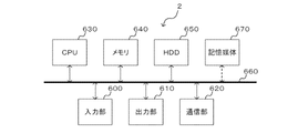
- FIG. 7 is a diagram showing a hardware configuration example of the transmitting station 2 (or the receiving station 3 and the relay station 4) according to the embodiment.
- the transmission station 2 has an input unit 600, an output unit 610, a communication unit 620, a CPU 630, a memory 640, and an HDD 650 connected via a bus 660, and has a function as a computer.
- the transmitting station 2 is configured to be able to input / output data to / from a computer-readable storage medium 670.
- the input unit 600 is, for example, a keyboard, a mouse, or the like.
- the output unit 610 is a display device such as a display.
- the communication unit 620 is, for example, a wireless network interface.
- the CPU 630 controls each part constituting the transmitting station 2 and performs predetermined processing and the like.
- the memory 640 and the HDD 650 are storage units for storing data and the like.
- the storage medium 670 is capable of storing a program or the like for executing the function of the transmitting station 2.
- the architecture constituting the transmitting station 2 is not limited to the example shown in FIG. 7.
- 1,1a ... wireless communication system 2 ... transmitting station, 3 ... receiving station, 4 ... relay station, 5-1, 5-2 ... receiving station, 20 ... control unit , 22 ... Modulation unit, 24 ... NOMA processing unit, 26 ... Communication unit, 28 ... Antenna, 31 ... Antenna, 32 ... Communication unit, 33 ... First demodulation unit , 34 ... Replica creation unit, 35 ... Subtraction unit, 36 ... Synthesis unit, 37 ... Second demodulation unit, 240 ... Conversion unit, 242 ... Superimposition unit, 260 ... Transmitter, 262 ... Receiver, 320 ... Receiver, 322 ... Transmitter, 600 ... Input, 610 ... Output, 620 ... Communication, 630 ... CPU , 640 ... Memory, 650 ... HDD, 660 ... Bus, 670 ... Storage medium
Landscapes
- Engineering & Computer Science (AREA)
- Signal Processing (AREA)
- Computer Networks & Wireless Communication (AREA)
- Mobile Radio Communication Systems (AREA)
- Radio Transmission System (AREA)
Abstract
Description
Claims (8)
- n個(n≧2)の周波数チャネルを用いて送信装置と受信装置とが無線通信を行う無線通信システムにおいて、
前記送信装置は、
n+1個の信号を、C/Nを所定値に定められたn個の所定電力信号と、C/Nをそれぞれ所定値の1/nにしてn個に分割した分割信号とに変換する変換部と、
前記変換部が変換したn個の所定電力信号とn個の分割信号とを、n個の前記周波数チャネルに対するn個の多重信号となるようにそれぞれ非直交に重畳させる重畳部と、
前記重畳部が重畳させたn個の多重信号をn個の前記周波数チャネルによって同時に送信する送信部と
を有し、
前記受信装置は、
n個の前記周波数チャネルによって送信されたn個の多重信号を受信する受信部と、
前記受信部が受信したn個の多重信号からn個の所定電力信号を復調する復調部と、
前記復調部が復調したn個の所定電力信号それぞれを複製し、n個のレプリカ信号を作成するレプリカ作成部と、
前記レプリカ作成部が作成したn個のレプリカ信号それぞれを、前記受信部が受信したn個の多重信号それぞれから減算し、n個の減算後信号を算出する減算部と、
前記減算部が算出したn個の減算後信号を合成する合成部と
を有することを特徴とする無線通信システム。 - n個の前記周波数チャネルは、
それぞれ偏波面及び周波数の少なくともいずれかが異なること
を特徴とする請求項1に記載の無線通信システム。 - 前記受信装置は、
前記復調部が復調したn個の所定電力信号をn個の前記周波数チャネルによって第1の無線通信装置へ伝送し、前記合成部が合成した減算後信号をn個の前記周波数チャネルのいずれかによって前記第1の無線通信装置とは異なる方向に配置された第2の無線通信装置へ伝送する伝送部をさらに有すること
を特徴とする請求項1又は2に記載の無線通信システム。 - n個(n≧2)の周波数チャネルを用いて送信装置と受信装置とが無線通信を行う無線通信方法において、
n+1個の信号を、C/Nを所定値に定められたn個の所定電力信号と、C/Nをそれぞれ所定値の1/nにしてn個に分割した分割信号とに変換する変換工程と、
変換したn個の所定電力信号とn個の分割信号とを、n個の前記周波数チャネルに対するn個の多重信号となるようにそれぞれ非直交に重畳させる重畳工程と、
重畳させたn個の多重信号をn個の前記周波数チャネルによって同時に送信する送信工程と、
n個の前記周波数チャネルによって送信されたn個の多重信号を受信する受信工程と、
受信したn個の多重信号からn個の所定電力信号を復調する復調工程と、
復調したn個の所定電力信号それぞれを複製し、n個のレプリカ信号を作成するレプリカ作成工程と、
作成したn個のレプリカ信号それぞれを、受信したn個の多重信号それぞれから減算し、n個の減算後信号を算出する減算工程と、
算出したn個の減算後信号を合成する合成工程と
を含むことを特徴とする無線通信方法。 - n個(n≧2)の周波数チャネルを用いて受信装置との間で無線通信を行う送信装置において、
n+1個の信号を、C/Nを所定値に定められたn個の所定電力信号と、C/Nをそれぞれ所定値の1/nにしてn個に分割した分割信号とに変換する変換部と、
前記変換部が変換したn個の所定電力信号とn個の分割信号とを、n個の前記周波数チャネルに対するn個の多重信号となるようにそれぞれ非直交に重畳させる重畳部と、
前記重畳部が重畳させたn個の多重信号をn個の前記周波数チャネルによって同時に送信する送信部と
を有することを特徴とする送信装置。 - n個の前記周波数チャネルは、
それぞれ偏波面及び周波数の少なくともいずれかが異なること
を特徴とする請求項5に記載の送信装置。 - n個(n≧2)の周波数チャネルを用いて送信装置と無線通信を行う受信装置において、
n個の前記周波数チャネルによって送信されたn個の多重信号を受信する受信部と、
前記受信部が受信したn個の多重信号からn個の所定電力信号を復調する復調部と、
前記復調部が復調したn個の所定電力信号それぞれを複製し、n個のレプリカ信号を作成するレプリカ作成部と、
前記レプリカ作成部が作成したn個のレプリカ信号それぞれを、前記受信部が受信したn個の多重信号それぞれから減算し、n個の減算後信号を算出する減算部と、
前記減算部が算出したn個の減算後信号を合成する合成部と
を有することを特徴とする受信装置。 - n個の前記周波数チャネルは、
それぞれ偏波面及び周波数の少なくともいずれかが異なること
を特徴とする請求項7に記載の受信装置。
Priority Applications (3)
| Application Number | Priority Date | Filing Date | Title |
|---|---|---|---|
| US18/039,449 US12355549B2 (en) | 2020-12-21 | 2020-12-21 | Wireless communication system, wireless communication method, transmitter, and receiver |
| JP2022570773A JP7529045B2 (ja) | 2020-12-21 | 2020-12-21 | 無線通信システム、無線通信方法、送信装置、及び受信装置 |
| PCT/JP2020/047669 WO2022137282A1 (ja) | 2020-12-21 | 2020-12-21 | 無線通信システム、無線通信方法、送信装置、及び受信装置 |
Applications Claiming Priority (1)
| Application Number | Priority Date | Filing Date | Title |
|---|---|---|---|
| PCT/JP2020/047669 WO2022137282A1 (ja) | 2020-12-21 | 2020-12-21 | 無線通信システム、無線通信方法、送信装置、及び受信装置 |
Publications (1)
| Publication Number | Publication Date |
|---|---|
| WO2022137282A1 true WO2022137282A1 (ja) | 2022-06-30 |
Family
ID=82158628
Family Applications (1)
| Application Number | Title | Priority Date | Filing Date |
|---|---|---|---|
| PCT/JP2020/047669 Ceased WO2022137282A1 (ja) | 2020-12-21 | 2020-12-21 | 無線通信システム、無線通信方法、送信装置、及び受信装置 |
Country Status (3)
| Country | Link |
|---|---|
| US (1) | US12355549B2 (ja) |
| JP (1) | JP7529045B2 (ja) |
| WO (1) | WO2022137282A1 (ja) |
Families Citing this family (1)
| Publication number | Priority date | Publication date | Assignee | Title |
|---|---|---|---|---|
| WO2023162104A1 (ja) * | 2022-02-24 | 2023-08-31 | 日本電信電話株式会社 | 電波の到来方向推定装置、及び電波の到来方向推定方法 |
Citations (3)
| Publication number | Priority date | Publication date | Assignee | Title |
|---|---|---|---|---|
| JP2013247513A (ja) * | 2012-05-25 | 2013-12-09 | Sharp Corp | 受信局装置、送信局装置、通信システム、受信方法、送信方法及びプログラム |
| JP2015039132A (ja) * | 2013-08-19 | 2015-02-26 | 株式会社Nttドコモ | 無線通信システムおよびユーザ装置 |
| JP2016174288A (ja) * | 2015-03-17 | 2016-09-29 | 日本電信電話株式会社 | 無線通信システムおよび無線通信方法 |
Family Cites Families (1)
| Publication number | Priority date | Publication date | Assignee | Title |
|---|---|---|---|---|
| JP2006527573A (ja) * | 2003-06-13 | 2006-11-30 | 松下電器産業株式会社 | スプリアス信号成分を減少するために利得を制御する光伝送システム |
-
2020
- 2020-12-21 US US18/039,449 patent/US12355549B2/en active Active
- 2020-12-21 JP JP2022570773A patent/JP7529045B2/ja active Active
- 2020-12-21 WO PCT/JP2020/047669 patent/WO2022137282A1/ja not_active Ceased
Patent Citations (3)
| Publication number | Priority date | Publication date | Assignee | Title |
|---|---|---|---|---|
| JP2013247513A (ja) * | 2012-05-25 | 2013-12-09 | Sharp Corp | 受信局装置、送信局装置、通信システム、受信方法、送信方法及びプログラム |
| JP2015039132A (ja) * | 2013-08-19 | 2015-02-26 | 株式会社Nttドコモ | 無線通信システムおよびユーザ装置 |
| JP2016174288A (ja) * | 2015-03-17 | 2016-09-29 | 日本電信電話株式会社 | 無線通信システムおよび無線通信方法 |
Also Published As
| Publication number | Publication date |
|---|---|
| JPWO2022137282A1 (ja) | 2022-06-30 |
| JP7529045B2 (ja) | 2024-08-06 |
| US20240007212A1 (en) | 2024-01-04 |
| US12355549B2 (en) | 2025-07-08 |
Similar Documents
| Publication | Publication Date | Title |
|---|---|---|
| JP6697731B2 (ja) | 送信装置、受信装置、および通信方法 | |
| US5038341A (en) | Relay communication system | |
| RU2341019C1 (ru) | Способ передачи и приема информации в прямом и обратном направлениях | |
| JP2010011071A (ja) | 信号変換器、無線信号送信システム及び無線信号受信システム | |
| CN102136862B (zh) | 基站设备、通信系统和通信方法 | |
| JP6462289B2 (ja) | 送信装置及び受信装置 | |
| US20090022231A1 (en) | Communication apparatus | |
| JP6271954B2 (ja) | Mimo受信システム、mimo受信装置、mimo送信装置及びmimo送受信システム | |
| JP7529045B2 (ja) | 無線通信システム、無線通信方法、送信装置、及び受信装置 | |
| JP5788269B2 (ja) | データ送信装置およびデータ受信装置 | |
| JP5282662B2 (ja) | 無線中継装置、中継方法 | |
| CN1612555B (zh) | 减小地面数字电视广播系统中同频转发器时延的调制设备 | |
| JP2010161585A (ja) | 空間多重伝送用送信アダプタおよび空間多重伝送用受信アダプタ | |
| JP6635918B2 (ja) | 無線基地局、親局装置、子局装置、および制御方法 | |
| JP6431293B2 (ja) | 受信システム | |
| JP2007006219A (ja) | アダプティブアンテナ装置 | |
| US10148338B1 (en) | Wireless communication system | |
| JP6025192B2 (ja) | 無線lan通信装置、無線lan通信装置制御プログラム、及び無線lan通信装置制御方法 | |
| CN114172780B (zh) | 基于天线选择和极化滤波的通信传输方法及装置 | |
| JP5437508B1 (ja) | 受信装置、受信方法および周波数誤差推定回路 | |
| KR100340032B1 (ko) | 원편파를 이용한 기지국 송신장치 및 가입자 수신장치와 그를 이용한 셀 설계 및 확장 방법 | |
| JP5157550B2 (ja) | 信号分配装置、無線装置及び通信システム | |
| JP5296240B1 (ja) | 受信装置および受信方法 | |
| JP7582339B2 (ja) | 無線通信システム、無線通信方法、送信側システム、及び受信側システム | |
| WO2011086921A1 (ja) | 中継装置および中継方法 |
Legal Events
| Date | Code | Title | Description |
|---|---|---|---|
| 121 | Ep: the epo has been informed by wipo that ep was designated in this application |
Ref document number: 20966781 Country of ref document: EP Kind code of ref document: A1 |
|
| ENP | Entry into the national phase |
Ref document number: 2022570773 Country of ref document: JP Kind code of ref document: A |
|
| WWE | Wipo information: entry into national phase |
Ref document number: 18039449 Country of ref document: US |
|
| NENP | Non-entry into the national phase |
Ref country code: DE |
|
| 122 | Ep: pct application non-entry in european phase |
Ref document number: 20966781 Country of ref document: EP Kind code of ref document: A1 |
|
| WWG | Wipo information: grant in national office |
Ref document number: 18039449 Country of ref document: US |