WO2022124308A1 - Lcp押出フィルム及びその製造方法、延伸処理用lcp押出フィルム、lcp延伸フィルム、熱収縮性lcp延伸フィルム、回路基板用絶縁材料、並びに金属箔張積層板 - Google Patents
Lcp押出フィルム及びその製造方法、延伸処理用lcp押出フィルム、lcp延伸フィルム、熱収縮性lcp延伸フィルム、回路基板用絶縁材料、並びに金属箔張積層板 Download PDFInfo
- Publication number
- WO2022124308A1 WO2022124308A1 PCT/JP2021/044969 JP2021044969W WO2022124308A1 WO 2022124308 A1 WO2022124308 A1 WO 2022124308A1 JP 2021044969 W JP2021044969 W JP 2021044969W WO 2022124308 A1 WO2022124308 A1 WO 2022124308A1
- Authority
- WO
- WIPO (PCT)
- Prior art keywords
- lcp
- film
- extruded film
- liquid crystal
- lcp extruded
- Prior art date
- Legal status (The legal status is an assumption and is not a legal conclusion. Google has not performed a legal analysis and makes no representation as to the accuracy of the status listed.)
- Ceased
Links
Images










Classifications
-
- B—PERFORMING OPERATIONS; TRANSPORTING
- B29—WORKING OF PLASTICS; WORKING OF SUBSTANCES IN A PLASTIC STATE IN GENERAL
- B29C—SHAPING OR JOINING OF PLASTICS; SHAPING OF MATERIAL IN A PLASTIC STATE, NOT OTHERWISE PROVIDED FOR; AFTER-TREATMENT OF THE SHAPED PRODUCTS, e.g. REPAIRING
- B29C48/00—Extrusion moulding, i.e. expressing the moulding material through a die or nozzle which imparts the desired form; Apparatus therefor
- B29C48/16—Articles comprising two or more components, e.g. co-extruded layers
- B29C48/18—Articles comprising two or more components, e.g. co-extruded layers the components being layers
- B29C48/23—Articles comprising two or more components, e.g. co-extruded layers the components being layers with means for avoiding adhesion of the layers, e.g. for forming peelable layers
-
- B—PERFORMING OPERATIONS; TRANSPORTING
- B29—WORKING OF PLASTICS; WORKING OF SUBSTANCES IN A PLASTIC STATE IN GENERAL
- B29C—SHAPING OR JOINING OF PLASTICS; SHAPING OF MATERIAL IN A PLASTIC STATE, NOT OTHERWISE PROVIDED FOR; AFTER-TREATMENT OF THE SHAPED PRODUCTS, e.g. REPAIRING
- B29C48/00—Extrusion moulding, i.e. expressing the moulding material through a die or nozzle which imparts the desired form; Apparatus therefor
- B29C48/001—Combinations of extrusion moulding with other shaping operations
- B29C48/002—Combinations of extrusion moulding with other shaping operations combined with surface shaping
-
- B—PERFORMING OPERATIONS; TRANSPORTING
- B29—WORKING OF PLASTICS; WORKING OF SUBSTANCES IN A PLASTIC STATE IN GENERAL
- B29C—SHAPING OR JOINING OF PLASTICS; SHAPING OF MATERIAL IN A PLASTIC STATE, NOT OTHERWISE PROVIDED FOR; AFTER-TREATMENT OF THE SHAPED PRODUCTS, e.g. REPAIRING
- B29C48/00—Extrusion moulding, i.e. expressing the moulding material through a die or nozzle which imparts the desired form; Apparatus therefor
- B29C48/022—Extrusion moulding, i.e. expressing the moulding material through a die or nozzle which imparts the desired form; Apparatus therefor characterised by the choice of material
-
- B—PERFORMING OPERATIONS; TRANSPORTING
- B29—WORKING OF PLASTICS; WORKING OF SUBSTANCES IN A PLASTIC STATE IN GENERAL
- B29C—SHAPING OR JOINING OF PLASTICS; SHAPING OF MATERIAL IN A PLASTIC STATE, NOT OTHERWISE PROVIDED FOR; AFTER-TREATMENT OF THE SHAPED PRODUCTS, e.g. REPAIRING
- B29C48/00—Extrusion moulding, i.e. expressing the moulding material through a die or nozzle which imparts the desired form; Apparatus therefor
- B29C48/03—Extrusion moulding, i.e. expressing the moulding material through a die or nozzle which imparts the desired form; Apparatus therefor characterised by the shape of the extruded material at extrusion
- B29C48/07—Flat, e.g. panels
- B29C48/08—Flat, e.g. panels flexible, e.g. films
-
- B—PERFORMING OPERATIONS; TRANSPORTING
- B29—WORKING OF PLASTICS; WORKING OF SUBSTANCES IN A PLASTIC STATE IN GENERAL
- B29C—SHAPING OR JOINING OF PLASTICS; SHAPING OF MATERIAL IN A PLASTIC STATE, NOT OTHERWISE PROVIDED FOR; AFTER-TREATMENT OF THE SHAPED PRODUCTS, e.g. REPAIRING
- B29C48/00—Extrusion moulding, i.e. expressing the moulding material through a die or nozzle which imparts the desired form; Apparatus therefor
- B29C48/14—Extrusion moulding, i.e. expressing the moulding material through a die or nozzle which imparts the desired form; Apparatus therefor characterised by the particular extruding conditions, e.g. in a modified atmosphere or by using vibration
- B29C48/146—Extrusion moulding, i.e. expressing the moulding material through a die or nozzle which imparts the desired form; Apparatus therefor characterised by the particular extruding conditions, e.g. in a modified atmosphere or by using vibration in the die
-
- B—PERFORMING OPERATIONS; TRANSPORTING
- B29—WORKING OF PLASTICS; WORKING OF SUBSTANCES IN A PLASTIC STATE IN GENERAL
- B29C—SHAPING OR JOINING OF PLASTICS; SHAPING OF MATERIAL IN A PLASTIC STATE, NOT OTHERWISE PROVIDED FOR; AFTER-TREATMENT OF THE SHAPED PRODUCTS, e.g. REPAIRING
- B29C48/00—Extrusion moulding, i.e. expressing the moulding material through a die or nozzle which imparts the desired form; Apparatus therefor
- B29C48/25—Component parts, details or accessories; Auxiliary operations
- B29C48/36—Means for plasticising or homogenising the moulding material or forcing it through the nozzle or die
- B29C48/395—Means for plasticising or homogenising the moulding material or forcing it through the nozzle or die using screws surrounded by a cooperating barrel, e.g. single screw extruders
-
- B—PERFORMING OPERATIONS; TRANSPORTING
- B29—WORKING OF PLASTICS; WORKING OF SUBSTANCES IN A PLASTIC STATE IN GENERAL
- B29C—SHAPING OR JOINING OF PLASTICS; SHAPING OF MATERIAL IN A PLASTIC STATE, NOT OTHERWISE PROVIDED FOR; AFTER-TREATMENT OF THE SHAPED PRODUCTS, e.g. REPAIRING
- B29C48/00—Extrusion moulding, i.e. expressing the moulding material through a die or nozzle which imparts the desired form; Apparatus therefor
- B29C48/25—Component parts, details or accessories; Auxiliary operations
- B29C48/78—Thermal treatment of the extrusion moulding material or of preformed parts or layers, e.g. by heating or cooling
-
- B—PERFORMING OPERATIONS; TRANSPORTING
- B29—WORKING OF PLASTICS; WORKING OF SUBSTANCES IN A PLASTIC STATE IN GENERAL
- B29C—SHAPING OR JOINING OF PLASTICS; SHAPING OF MATERIAL IN A PLASTIC STATE, NOT OTHERWISE PROVIDED FOR; AFTER-TREATMENT OF THE SHAPED PRODUCTS, e.g. REPAIRING
- B29C48/00—Extrusion moulding, i.e. expressing the moulding material through a die or nozzle which imparts the desired form; Apparatus therefor
- B29C48/25—Component parts, details or accessories; Auxiliary operations
- B29C48/92—Measuring, controlling or regulating
-
- B—PERFORMING OPERATIONS; TRANSPORTING
- B29—WORKING OF PLASTICS; WORKING OF SUBSTANCES IN A PLASTIC STATE IN GENERAL
- B29C—SHAPING OR JOINING OF PLASTICS; SHAPING OF MATERIAL IN A PLASTIC STATE, NOT OTHERWISE PROVIDED FOR; AFTER-TREATMENT OF THE SHAPED PRODUCTS, e.g. REPAIRING
- B29C55/00—Shaping by stretching, e.g. drawing through a die; Apparatus therefor
- B29C55/02—Shaping by stretching, e.g. drawing through a die; Apparatus therefor of plates or sheets
-
- B—PERFORMING OPERATIONS; TRANSPORTING
- B29—WORKING OF PLASTICS; WORKING OF SUBSTANCES IN A PLASTIC STATE IN GENERAL
- B29D—PRODUCING PARTICULAR ARTICLES FROM PLASTICS OR FROM SUBSTANCES IN A PLASTIC STATE
- B29D7/00—Producing flat articles, e.g. films or sheets
- B29D7/01—Films or sheets
-
- B—PERFORMING OPERATIONS; TRANSPORTING
- B32—LAYERED PRODUCTS
- B32B—LAYERED PRODUCTS, i.e. PRODUCTS BUILT-UP OF STRATA OF FLAT OR NON-FLAT, e.g. CELLULAR OR HONEYCOMB, FORM
- B32B15/00—Layered products comprising a layer of metal
- B32B15/04—Layered products comprising a layer of metal comprising metal as the main or only constituent of a layer, which is next to another layer of the same or of a different material
- B32B15/08—Layered products comprising a layer of metal comprising metal as the main or only constituent of a layer, which is next to another layer of the same or of a different material of synthetic resin
-
- B—PERFORMING OPERATIONS; TRANSPORTING
- B32—LAYERED PRODUCTS
- B32B—LAYERED PRODUCTS, i.e. PRODUCTS BUILT-UP OF STRATA OF FLAT OR NON-FLAT, e.g. CELLULAR OR HONEYCOMB, FORM
- B32B15/00—Layered products comprising a layer of metal
- B32B15/14—Layered products comprising a layer of metal next to a fibrous or filamentary layer
-
- B—PERFORMING OPERATIONS; TRANSPORTING
- B32—LAYERED PRODUCTS
- B32B—LAYERED PRODUCTS, i.e. PRODUCTS BUILT-UP OF STRATA OF FLAT OR NON-FLAT, e.g. CELLULAR OR HONEYCOMB, FORM
- B32B27/00—Layered products comprising a layer of synthetic resin
-
- B—PERFORMING OPERATIONS; TRANSPORTING
- B32—LAYERED PRODUCTS
- B32B—LAYERED PRODUCTS, i.e. PRODUCTS BUILT-UP OF STRATA OF FLAT OR NON-FLAT, e.g. CELLULAR OR HONEYCOMB, FORM
- B32B27/00—Layered products comprising a layer of synthetic resin
- B32B27/06—Layered products comprising a layer of synthetic resin as the main or only constituent of a layer, which is next to another layer of the same or of a different material
- B32B27/08—Layered products comprising a layer of synthetic resin as the main or only constituent of a layer, which is next to another layer of the same or of a different material of synthetic resin
-
- B—PERFORMING OPERATIONS; TRANSPORTING
- B32—LAYERED PRODUCTS
- B32B—LAYERED PRODUCTS, i.e. PRODUCTS BUILT-UP OF STRATA OF FLAT OR NON-FLAT, e.g. CELLULAR OR HONEYCOMB, FORM
- B32B27/00—Layered products comprising a layer of synthetic resin
- B32B27/12—Layered products comprising a layer of synthetic resin next to a fibrous or filamentary layer
-
- B—PERFORMING OPERATIONS; TRANSPORTING
- B32—LAYERED PRODUCTS
- B32B—LAYERED PRODUCTS, i.e. PRODUCTS BUILT-UP OF STRATA OF FLAT OR NON-FLAT, e.g. CELLULAR OR HONEYCOMB, FORM
- B32B27/00—Layered products comprising a layer of synthetic resin
- B32B27/18—Layered products comprising a layer of synthetic resin characterised by the use of special additives
- B32B27/20—Layered products comprising a layer of synthetic resin characterised by the use of special additives using fillers, pigments, thixotroping agents
-
- B—PERFORMING OPERATIONS; TRANSPORTING
- B32—LAYERED PRODUCTS
- B32B—LAYERED PRODUCTS, i.e. PRODUCTS BUILT-UP OF STRATA OF FLAT OR NON-FLAT, e.g. CELLULAR OR HONEYCOMB, FORM
- B32B27/00—Layered products comprising a layer of synthetic resin
- B32B27/28—Layered products comprising a layer of synthetic resin comprising synthetic resins not wholly covered by any one of the sub-groups B32B27/30 - B32B27/42
- B32B27/285—Layered products comprising a layer of synthetic resin comprising synthetic resins not wholly covered by any one of the sub-groups B32B27/30 - B32B27/42 comprising polyethers
-
- B—PERFORMING OPERATIONS; TRANSPORTING
- B32—LAYERED PRODUCTS
- B32B—LAYERED PRODUCTS, i.e. PRODUCTS BUILT-UP OF STRATA OF FLAT OR NON-FLAT, e.g. CELLULAR OR HONEYCOMB, FORM
- B32B27/00—Layered products comprising a layer of synthetic resin
- B32B27/30—Layered products comprising a layer of synthetic resin comprising vinyl (co)polymers; comprising acrylic (co)polymers
- B32B27/302—Layered products comprising a layer of synthetic resin comprising vinyl (co)polymers; comprising acrylic (co)polymers comprising aromatic vinyl (co)polymers, e.g. styrenic (co)polymers
-
- B—PERFORMING OPERATIONS; TRANSPORTING
- B32—LAYERED PRODUCTS
- B32B—LAYERED PRODUCTS, i.e. PRODUCTS BUILT-UP OF STRATA OF FLAT OR NON-FLAT, e.g. CELLULAR OR HONEYCOMB, FORM
- B32B27/00—Layered products comprising a layer of synthetic resin
- B32B27/30—Layered products comprising a layer of synthetic resin comprising vinyl (co)polymers; comprising acrylic (co)polymers
- B32B27/304—Layered products comprising a layer of synthetic resin comprising vinyl (co)polymers; comprising acrylic (co)polymers comprising vinyl halide (co)polymers, e.g. PVC, PVDC, PVF, PVDF
-
- B—PERFORMING OPERATIONS; TRANSPORTING
- B32—LAYERED PRODUCTS
- B32B—LAYERED PRODUCTS, i.e. PRODUCTS BUILT-UP OF STRATA OF FLAT OR NON-FLAT, e.g. CELLULAR OR HONEYCOMB, FORM
- B32B27/00—Layered products comprising a layer of synthetic resin
- B32B27/30—Layered products comprising a layer of synthetic resin comprising vinyl (co)polymers; comprising acrylic (co)polymers
- B32B27/308—Layered products comprising a layer of synthetic resin comprising vinyl (co)polymers; comprising acrylic (co)polymers comprising acrylic (co)polymers
-
- B—PERFORMING OPERATIONS; TRANSPORTING
- B32—LAYERED PRODUCTS
- B32B—LAYERED PRODUCTS, i.e. PRODUCTS BUILT-UP OF STRATA OF FLAT OR NON-FLAT, e.g. CELLULAR OR HONEYCOMB, FORM
- B32B27/00—Layered products comprising a layer of synthetic resin
- B32B27/32—Layered products comprising a layer of synthetic resin comprising polyolefins
-
- B—PERFORMING OPERATIONS; TRANSPORTING
- B32—LAYERED PRODUCTS
- B32B—LAYERED PRODUCTS, i.e. PRODUCTS BUILT-UP OF STRATA OF FLAT OR NON-FLAT, e.g. CELLULAR OR HONEYCOMB, FORM
- B32B27/00—Layered products comprising a layer of synthetic resin
- B32B27/34—Layered products comprising a layer of synthetic resin comprising polyamides
-
- B—PERFORMING OPERATIONS; TRANSPORTING
- B32—LAYERED PRODUCTS
- B32B—LAYERED PRODUCTS, i.e. PRODUCTS BUILT-UP OF STRATA OF FLAT OR NON-FLAT, e.g. CELLULAR OR HONEYCOMB, FORM
- B32B27/00—Layered products comprising a layer of synthetic resin
- B32B27/36—Layered products comprising a layer of synthetic resin comprising polyesters
-
- B—PERFORMING OPERATIONS; TRANSPORTING
- B32—LAYERED PRODUCTS
- B32B—LAYERED PRODUCTS, i.e. PRODUCTS BUILT-UP OF STRATA OF FLAT OR NON-FLAT, e.g. CELLULAR OR HONEYCOMB, FORM
- B32B27/00—Layered products comprising a layer of synthetic resin
- B32B27/36—Layered products comprising a layer of synthetic resin comprising polyesters
- B32B27/365—Layered products comprising a layer of synthetic resin comprising polyesters comprising polycarbonates
-
- B—PERFORMING OPERATIONS; TRANSPORTING
- B32—LAYERED PRODUCTS
- B32B—LAYERED PRODUCTS, i.e. PRODUCTS BUILT-UP OF STRATA OF FLAT OR NON-FLAT, e.g. CELLULAR OR HONEYCOMB, FORM
- B32B5/00—Layered products characterised by the non- homogeneity or physical structure, i.e. comprising a fibrous, filamentary, particulate or foam layer; Layered products characterised by having a layer differing constitutionally or physically in different parts
- B32B5/02—Layered products characterised by the non- homogeneity or physical structure, i.e. comprising a fibrous, filamentary, particulate or foam layer; Layered products characterised by having a layer differing constitutionally or physically in different parts characterised by structural features of a fibrous or filamentary layer
- B32B5/024—Woven fabric
-
- B—PERFORMING OPERATIONS; TRANSPORTING
- B32—LAYERED PRODUCTS
- B32B—LAYERED PRODUCTS, i.e. PRODUCTS BUILT-UP OF STRATA OF FLAT OR NON-FLAT, e.g. CELLULAR OR HONEYCOMB, FORM
- B32B7/00—Layered products characterised by the relation between layers; Layered products characterised by the relative orientation of features between layers, or by the relative values of a measurable parameter between layers, i.e. products comprising layers having different physical, chemical or physicochemical properties; Layered products characterised by the interconnection of layers
- B32B7/04—Interconnection of layers
- B32B7/06—Interconnection of layers permitting easy separation
-
- C—CHEMISTRY; METALLURGY
- C08—ORGANIC MACROMOLECULAR COMPOUNDS; THEIR PREPARATION OR CHEMICAL WORKING-UP; COMPOSITIONS BASED THEREON
- C08J—WORKING-UP; GENERAL PROCESSES OF COMPOUNDING; AFTER-TREATMENT NOT COVERED BY SUBCLASSES C08B, C08C, C08F, C08G or C08H
- C08J5/00—Manufacture of articles or shaped materials containing macromolecular substances
- C08J5/04—Reinforcing macromolecular compounds with loose or coherent fibrous material
-
- C—CHEMISTRY; METALLURGY
- C08—ORGANIC MACROMOLECULAR COMPOUNDS; THEIR PREPARATION OR CHEMICAL WORKING-UP; COMPOSITIONS BASED THEREON
- C08J—WORKING-UP; GENERAL PROCESSES OF COMPOUNDING; AFTER-TREATMENT NOT COVERED BY SUBCLASSES C08B, C08C, C08F, C08G or C08H
- C08J5/00—Manufacture of articles or shaped materials containing macromolecular substances
- C08J5/18—Manufacture of films or sheets
-
- C—CHEMISTRY; METALLURGY
- C09—DYES; PAINTS; POLISHES; NATURAL RESINS; ADHESIVES; COMPOSITIONS NOT OTHERWISE PROVIDED FOR; APPLICATIONS OF MATERIALS NOT OTHERWISE PROVIDED FOR
- C09K—MATERIALS FOR MISCELLANEOUS APPLICATIONS, NOT PROVIDED FOR ELSEWHERE
- C09K19/00—Liquid crystal materials
- C09K19/04—Liquid crystal materials characterised by the chemical structure of the liquid crystal components, e.g. by a specific unit
- C09K19/38—Polymers
- C09K19/3804—Polymers with mesogenic groups in the main chain
- C09K19/3809—Polyesters; Polyester derivatives, e.g. polyamides
-
- H—ELECTRICITY
- H05—ELECTRIC TECHNIQUES NOT OTHERWISE PROVIDED FOR
- H05K—PRINTED CIRCUITS; CASINGS OR CONSTRUCTIONAL DETAILS OF ELECTRIC APPARATUS; MANUFACTURE OF ASSEMBLAGES OF ELECTRICAL COMPONENTS
- H05K1/00—Printed circuits
- H05K1/02—Details
- H05K1/03—Use of materials for the substrate
-
- H—ELECTRICITY
- H05—ELECTRIC TECHNIQUES NOT OTHERWISE PROVIDED FOR
- H05K—PRINTED CIRCUITS; CASINGS OR CONSTRUCTIONAL DETAILS OF ELECTRIC APPARATUS; MANUFACTURE OF ASSEMBLAGES OF ELECTRICAL COMPONENTS
- H05K1/00—Printed circuits
- H05K1/02—Details
- H05K1/03—Use of materials for the substrate
- H05K1/0313—Organic insulating material
- H05K1/0353—Organic insulating material consisting of two or more materials, e.g. two or more polymers, polymer + filler, + reinforcement
- H05K1/0366—Organic insulating material consisting of two or more materials, e.g. two or more polymers, polymer + filler, + reinforcement reinforced, e.g. by fibres, fabrics
-
- B—PERFORMING OPERATIONS; TRANSPORTING
- B29—WORKING OF PLASTICS; WORKING OF SUBSTANCES IN A PLASTIC STATE IN GENERAL
- B29C—SHAPING OR JOINING OF PLASTICS; SHAPING OF MATERIAL IN A PLASTIC STATE, NOT OTHERWISE PROVIDED FOR; AFTER-TREATMENT OF THE SHAPED PRODUCTS, e.g. REPAIRING
- B29C48/00—Extrusion moulding, i.e. expressing the moulding material through a die or nozzle which imparts the desired form; Apparatus therefor
- B29C48/001—Combinations of extrusion moulding with other shaping operations
- B29C48/0021—Combinations of extrusion moulding with other shaping operations combined with joining, lining or laminating
-
- B—PERFORMING OPERATIONS; TRANSPORTING
- B29—WORKING OF PLASTICS; WORKING OF SUBSTANCES IN A PLASTIC STATE IN GENERAL
- B29C—SHAPING OR JOINING OF PLASTICS; SHAPING OF MATERIAL IN A PLASTIC STATE, NOT OTHERWISE PROVIDED FOR; AFTER-TREATMENT OF THE SHAPED PRODUCTS, e.g. REPAIRING
- B29C48/00—Extrusion moulding, i.e. expressing the moulding material through a die or nozzle which imparts the desired form; Apparatus therefor
- B29C48/16—Articles comprising two or more components, e.g. co-extruded layers
- B29C48/18—Articles comprising two or more components, e.g. co-extruded layers the components being layers
- B29C48/21—Articles comprising two or more components, e.g. co-extruded layers the components being layers the layers being joined at their surfaces
-
- B—PERFORMING OPERATIONS; TRANSPORTING
- B29—WORKING OF PLASTICS; WORKING OF SUBSTANCES IN A PLASTIC STATE IN GENERAL
- B29C—SHAPING OR JOINING OF PLASTICS; SHAPING OF MATERIAL IN A PLASTIC STATE, NOT OTHERWISE PROVIDED FOR; AFTER-TREATMENT OF THE SHAPED PRODUCTS, e.g. REPAIRING
- B29C48/00—Extrusion moulding, i.e. expressing the moulding material through a die or nozzle which imparts the desired form; Apparatus therefor
- B29C48/25—Component parts, details or accessories; Auxiliary operations
- B29C48/30—Extrusion nozzles or dies
- B29C48/305—Extrusion nozzles or dies having a wide opening, e.g. for forming sheets
-
- B—PERFORMING OPERATIONS; TRANSPORTING
- B29—WORKING OF PLASTICS; WORKING OF SUBSTANCES IN A PLASTIC STATE IN GENERAL
- B29K—INDEXING SCHEME ASSOCIATED WITH SUBCLASSES B29B, B29C OR B29D, RELATING TO MOULDING MATERIALS OR TO MATERIALS FOR MOULDS, REINFORCEMENTS, FILLERS OR PREFORMED PARTS, e.g. INSERTS
- B29K2067/00—Use of polyesters or derivatives thereof, as moulding material
-
- B—PERFORMING OPERATIONS; TRANSPORTING
- B29—WORKING OF PLASTICS; WORKING OF SUBSTANCES IN A PLASTIC STATE IN GENERAL
- B29K—INDEXING SCHEME ASSOCIATED WITH SUBCLASSES B29B, B29C OR B29D, RELATING TO MOULDING MATERIALS OR TO MATERIALS FOR MOULDS, REINFORCEMENTS, FILLERS OR PREFORMED PARTS, e.g. INSERTS
- B29K2105/00—Condition, form or state of moulded material or of the material to be shaped
- B29K2105/0079—Liquid crystals
-
- B—PERFORMING OPERATIONS; TRANSPORTING
- B29—WORKING OF PLASTICS; WORKING OF SUBSTANCES IN A PLASTIC STATE IN GENERAL
- B29K—INDEXING SCHEME ASSOCIATED WITH SUBCLASSES B29B, B29C OR B29D, RELATING TO MOULDING MATERIALS OR TO MATERIALS FOR MOULDS, REINFORCEMENTS, FILLERS OR PREFORMED PARTS, e.g. INSERTS
- B29K2105/00—Condition, form or state of moulded material or of the material to be shaped
- B29K2105/06—Condition, form or state of moulded material or of the material to be shaped containing reinforcements, fillers or inserts
- B29K2105/16—Fillers
-
- B—PERFORMING OPERATIONS; TRANSPORTING
- B29—WORKING OF PLASTICS; WORKING OF SUBSTANCES IN A PLASTIC STATE IN GENERAL
- B29K—INDEXING SCHEME ASSOCIATED WITH SUBCLASSES B29B, B29C OR B29D, RELATING TO MOULDING MATERIALS OR TO MATERIALS FOR MOULDS, REINFORCEMENTS, FILLERS OR PREFORMED PARTS, e.g. INSERTS
- B29K2509/00—Use of inorganic materials not provided for in groups B29K2503/00 - B29K2507/00, as filler
-
- B—PERFORMING OPERATIONS; TRANSPORTING
- B29—WORKING OF PLASTICS; WORKING OF SUBSTANCES IN A PLASTIC STATE IN GENERAL
- B29K—INDEXING SCHEME ASSOCIATED WITH SUBCLASSES B29B, B29C OR B29D, RELATING TO MOULDING MATERIALS OR TO MATERIALS FOR MOULDS, REINFORCEMENTS, FILLERS OR PREFORMED PARTS, e.g. INSERTS
- B29K2995/00—Properties of moulding materials, reinforcements, fillers, preformed parts or moulds
- B29K2995/0012—Properties of moulding materials, reinforcements, fillers, preformed parts or moulds having particular thermal properties
-
- B—PERFORMING OPERATIONS; TRANSPORTING
- B29—WORKING OF PLASTICS; WORKING OF SUBSTANCES IN A PLASTIC STATE IN GENERAL
- B29K—INDEXING SCHEME ASSOCIATED WITH SUBCLASSES B29B, B29C OR B29D, RELATING TO MOULDING MATERIALS OR TO MATERIALS FOR MOULDS, REINFORCEMENTS, FILLERS OR PREFORMED PARTS, e.g. INSERTS
- B29K2995/00—Properties of moulding materials, reinforcements, fillers, preformed parts or moulds
- B29K2995/0037—Other properties
- B29K2995/005—Oriented
-
- B—PERFORMING OPERATIONS; TRANSPORTING
- B29—WORKING OF PLASTICS; WORKING OF SUBSTANCES IN A PLASTIC STATE IN GENERAL
- B29K—INDEXING SCHEME ASSOCIATED WITH SUBCLASSES B29B, B29C OR B29D, RELATING TO MOULDING MATERIALS OR TO MATERIALS FOR MOULDS, REINFORCEMENTS, FILLERS OR PREFORMED PARTS, e.g. INSERTS
- B29K2995/00—Properties of moulding materials, reinforcements, fillers, preformed parts or moulds
- B29K2995/0037—Other properties
- B29K2995/007—Hardness
-
- B—PERFORMING OPERATIONS; TRANSPORTING
- B29—WORKING OF PLASTICS; WORKING OF SUBSTANCES IN A PLASTIC STATE IN GENERAL
- B29K—INDEXING SCHEME ASSOCIATED WITH SUBCLASSES B29B, B29C OR B29D, RELATING TO MOULDING MATERIALS OR TO MATERIALS FOR MOULDS, REINFORCEMENTS, FILLERS OR PREFORMED PARTS, e.g. INSERTS
- B29K2995/00—Properties of moulding materials, reinforcements, fillers, preformed parts or moulds
- B29K2995/0037—Other properties
- B29K2995/0094—Geometrical properties
- B29K2995/0097—Thickness
-
- B—PERFORMING OPERATIONS; TRANSPORTING
- B29—WORKING OF PLASTICS; WORKING OF SUBSTANCES IN A PLASTIC STATE IN GENERAL
- B29L—INDEXING SCHEME ASSOCIATED WITH SUBCLASS B29C, RELATING TO PARTICULAR ARTICLES
- B29L2009/00—Layered products
-
- B—PERFORMING OPERATIONS; TRANSPORTING
- B29—WORKING OF PLASTICS; WORKING OF SUBSTANCES IN A PLASTIC STATE IN GENERAL
- B29L—INDEXING SCHEME ASSOCIATED WITH SUBCLASS B29C, RELATING TO PARTICULAR ARTICLES
- B29L2031/00—Other particular articles
- B29L2031/34—Electrical apparatus, e.g. sparking plugs or parts thereof
- B29L2031/3425—Printed circuits
-
- B—PERFORMING OPERATIONS; TRANSPORTING
- B32—LAYERED PRODUCTS
- B32B—LAYERED PRODUCTS, i.e. PRODUCTS BUILT-UP OF STRATA OF FLAT OR NON-FLAT, e.g. CELLULAR OR HONEYCOMB, FORM
- B32B2250/00—Layers arrangement
- B32B2250/03—3 layers
-
- B—PERFORMING OPERATIONS; TRANSPORTING
- B32—LAYERED PRODUCTS
- B32B—LAYERED PRODUCTS, i.e. PRODUCTS BUILT-UP OF STRATA OF FLAT OR NON-FLAT, e.g. CELLULAR OR HONEYCOMB, FORM
- B32B2250/00—Layers arrangement
- B32B2250/24—All layers being polymeric
-
- B—PERFORMING OPERATIONS; TRANSPORTING
- B32—LAYERED PRODUCTS
- B32B—LAYERED PRODUCTS, i.e. PRODUCTS BUILT-UP OF STRATA OF FLAT OR NON-FLAT, e.g. CELLULAR OR HONEYCOMB, FORM
- B32B2305/00—Condition, form or state of the layers or laminate
- B32B2305/55—Liquid crystals
-
- B—PERFORMING OPERATIONS; TRANSPORTING
- B32—LAYERED PRODUCTS
- B32B—LAYERED PRODUCTS, i.e. PRODUCTS BUILT-UP OF STRATA OF FLAT OR NON-FLAT, e.g. CELLULAR OR HONEYCOMB, FORM
- B32B2307/00—Properties of the layers or laminate
- B32B2307/30—Properties of the layers or laminate having particular thermal properties
-
- B—PERFORMING OPERATIONS; TRANSPORTING
- B32—LAYERED PRODUCTS
- B32B—LAYERED PRODUCTS, i.e. PRODUCTS BUILT-UP OF STRATA OF FLAT OR NON-FLAT, e.g. CELLULAR OR HONEYCOMB, FORM
- B32B2307/00—Properties of the layers or laminate
- B32B2307/50—Properties of the layers or laminate having particular mechanical properties
- B32B2307/536—Hardness
-
- B—PERFORMING OPERATIONS; TRANSPORTING
- B32—LAYERED PRODUCTS
- B32B—LAYERED PRODUCTS, i.e. PRODUCTS BUILT-UP OF STRATA OF FLAT OR NON-FLAT, e.g. CELLULAR OR HONEYCOMB, FORM
- B32B2307/00—Properties of the layers or laminate
- B32B2307/70—Other properties
- B32B2307/732—Dimensional properties
- B32B2307/737—Dimensions, e.g. volume or area
- B32B2307/7375—Linear, e.g. length, distance or width
- B32B2307/7376—Thickness
-
- B—PERFORMING OPERATIONS; TRANSPORTING
- B32—LAYERED PRODUCTS
- B32B—LAYERED PRODUCTS, i.e. PRODUCTS BUILT-UP OF STRATA OF FLAT OR NON-FLAT, e.g. CELLULAR OR HONEYCOMB, FORM
- B32B2307/00—Properties of the layers or laminate
- B32B2307/70—Other properties
- B32B2307/748—Releasability
-
- B—PERFORMING OPERATIONS; TRANSPORTING
- B32—LAYERED PRODUCTS
- B32B—LAYERED PRODUCTS, i.e. PRODUCTS BUILT-UP OF STRATA OF FLAT OR NON-FLAT, e.g. CELLULAR OR HONEYCOMB, FORM
- B32B2355/00—Specific polymers obtained by polymerisation reactions only involving carbon-to-carbon unsaturated bonds, not provided for in a single one of index codes B32B2323/00 - B32B2333/00
- B32B2355/02—ABS polymers, i.e. acrylonitrile-butadiene-styrene polymers
-
- B—PERFORMING OPERATIONS; TRANSPORTING
- B32—LAYERED PRODUCTS
- B32B—LAYERED PRODUCTS, i.e. PRODUCTS BUILT-UP OF STRATA OF FLAT OR NON-FLAT, e.g. CELLULAR OR HONEYCOMB, FORM
- B32B2457/00—Electrical equipment
- B32B2457/08—PCBs, i.e. printed circuit boards
-
- C—CHEMISTRY; METALLURGY
- C08—ORGANIC MACROMOLECULAR COMPOUNDS; THEIR PREPARATION OR CHEMICAL WORKING-UP; COMPOSITIONS BASED THEREON
- C08J—WORKING-UP; GENERAL PROCESSES OF COMPOUNDING; AFTER-TREATMENT NOT COVERED BY SUBCLASSES C08B, C08C, C08F, C08G or C08H
- C08J2367/00—Characterised by the use of polyesters obtained by reactions forming a carboxylic ester link in the main chain; Derivatives of such polymers
- C08J2367/04—Polyesters derived from hydroxy carboxylic acids, e.g. lactones
-
- C—CHEMISTRY; METALLURGY
- C09—DYES; PAINTS; POLISHES; NATURAL RESINS; ADHESIVES; COMPOSITIONS NOT OTHERWISE PROVIDED FOR; APPLICATIONS OF MATERIALS NOT OTHERWISE PROVIDED FOR
- C09K—MATERIALS FOR MISCELLANEOUS APPLICATIONS, NOT PROVIDED FOR ELSEWHERE
- C09K2219/00—Aspects relating to the form of the liquid crystal [LC] material, or by the technical area in which LC material are used
- C09K2219/03—Aspects relating to the form of the liquid crystal [LC] material, or by the technical area in which LC material are used in the form of films, e.g. films after polymerisation of LC precursor
-
- H—ELECTRICITY
- H05—ELECTRIC TECHNIQUES NOT OTHERWISE PROVIDED FOR
- H05K—PRINTED CIRCUITS; CASINGS OR CONSTRUCTIONAL DETAILS OF ELECTRIC APPARATUS; MANUFACTURE OF ASSEMBLAGES OF ELECTRICAL COMPONENTS
- H05K2201/00—Indexing scheme relating to printed circuits covered by H05K1/00
- H05K2201/01—Dielectrics
- H05K2201/0104—Properties and characteristics in general
- H05K2201/0125—Shrinkable, e.g. heat-shrinkable polymer
-
- H—ELECTRICITY
- H05—ELECTRIC TECHNIQUES NOT OTHERWISE PROVIDED FOR
- H05K—PRINTED CIRCUITS; CASINGS OR CONSTRUCTIONAL DETAILS OF ELECTRIC APPARATUS; MANUFACTURE OF ASSEMBLAGES OF ELECTRICAL COMPONENTS
- H05K2201/00—Indexing scheme relating to printed circuits covered by H05K1/00
- H05K2201/01—Dielectrics
- H05K2201/0104—Properties and characteristics in general
- H05K2201/0129—Thermoplastic polymer, e.g. auto-adhesive layer; Shaping of thermoplastic polymer
-
- H—ELECTRICITY
- H05—ELECTRIC TECHNIQUES NOT OTHERWISE PROVIDED FOR
- H05K—PRINTED CIRCUITS; CASINGS OR CONSTRUCTIONAL DETAILS OF ELECTRIC APPARATUS; MANUFACTURE OF ASSEMBLAGES OF ELECTRICAL COMPONENTS
- H05K2201/00—Indexing scheme relating to printed circuits covered by H05K1/00
- H05K2201/01—Dielectrics
- H05K2201/0137—Materials
- H05K2201/0141—Liquid crystal polymer [LCP]
-
- H—ELECTRICITY
- H05—ELECTRIC TECHNIQUES NOT OTHERWISE PROVIDED FOR
- H05K—PRINTED CIRCUITS; CASINGS OR CONSTRUCTIONAL DETAILS OF ELECTRIC APPARATUS; MANUFACTURE OF ASSEMBLAGES OF ELECTRICAL COMPONENTS
- H05K2201/00—Indexing scheme relating to printed circuits covered by H05K1/00
- H05K2201/02—Fillers; Particles; Fibers; Reinforcement materials
- H05K2201/0275—Fibers and reinforcement materials
- H05K2201/029—Woven fibrous reinforcement or textile
Definitions
- the present invention relates to an LCP extruded film and a method for producing the same, an LCP extruded film for stretching treatment, an LCP stretched film, a heat-shrinkable LCP stretched film, an insulating material for a circuit board, a metal foil-clad laminate, and the like.
- a varnish-impregnated composite material in which a glass cloth is impregnated with a thermosetting resin such as an epoxy resin and a varnish containing an inorganic filler and a solvent, and then heat-press molded.
- a thermosetting resin such as an epoxy resin and a varnish containing an inorganic filler and a solvent
- this manufacturing method is inferior in productivity due to poor process margin during manufacturing, for example, from the viewpoint of resin flowability during varnish impregnation and curability during hot press molding.
- the thermosetting resin easily absorbs moisture, and its size changes with the moisture absorption, so that the dimensional accuracy (heating dimensional accuracy) of the obtained varnish-impregnated composite material is inferior.
- a liquid crystal polymer is a polymer that exhibits liquid crystal properties in a molten state or a solution state.
- the thermotropic liquid crystal polymer which exhibits liquid crystal properties in the molten state, can be extruded and has excellent properties such as high gas barrier properties, high film strength, high heat resistance, high insulation, low water absorption, and low dielectric properties in the high frequency range. It has the above-mentioned properties. Therefore, a film using a thermoplastic liquid crystal polymer is being studied for practical use in gas barrier film material applications, electronic material applications, and electrically insulating material applications.
- thermoplastic liquid crystal polymer film having high industrial utility value due to the high degree of liquid crystal orientation of the thermoplastic liquid crystal polymer, that is, an excellent appearance and appearance. It has been found that it is difficult to obtain a thermoplastic liquid crystal polymer film having good surface flatness.
- Patent Document 1 a three-layer co-extruded die is used instead of the single-layer extruded die, and a total aromatic polyester-based thermoplastic liquid crystal polymer is used as an intermediate layer, and a polyolefin resin or a polycarbonate resin is simultaneously extruded as both outer layers.
- the intermediate layer is a thermoplastic liquid crystal polymer layer and both outer layers are thermoplastic resin layers
- the thermoplastic resin layers of both outer layers are peeled off and the intermediate layer is taken out as a film. It is disclosed that a thermoplastic liquid crystal polymer film having excellent thickness accuracy and good appearance and surface flatness can be obtained.
- Insulation materials for circuit boards using liquid crystal polymers are excellent in high-frequency characteristics and low dielectric properties, so they are flexible printed wiring boards (FPCs) and flexible in the 5th generation mobile communication systems (5G) and millimeter-wave radars that will be developed in the future.
- FPCs flexible printed wiring boards
- 5G 5th generation mobile communication systems
- millimeter-wave radars millimeter-wave radars
- thermoplastic liquid crystal polymer film having excellent thickness accuracy and good appearance and surface flatness.
- thermoplasticity described in Patent Documents 1 and 2 can be suppressed.
- the thermoplastic liquid crystal polymer film the thermoplastic liquid crystal polymer is still highly molecularly oriented as a whole film, and it is not practically usable as an insulating material for a circuit board.
- thermoplastic liquid crystal polymer film may be used as a metal foil-clad laminate by thermocompression bonding a metal foil such as copper foil on one side and / or both sides thereof. be.
- a metal foil-clad laminate can be used as a material for a circuit board such as an electronic circuit board or a multilayer board. Therefore, the thermoplastic liquid crystal polymer film that supports the metal foil is required to have a high degree of dimensional stability.
- the thermoplastic liquid crystal polymer films described in Patent Documents 1 and 2 still have a large difference in the dimensional change rate in the TD direction and the MD direction after etching, and cannot meet the recent demand for application to ultrafine processing. rice field.
- An object of one aspect of the present invention is a novel LCP extruded film in which the molecular orientation, internal strain, etc. of the thermoplastic liquid crystal polymer are sufficiently reduced, and the anisotropy of the dimensional change rate is significantly reduced as compared with the conventional one. , And an LCP stretched film using the same, an insulating material for a circuit board, a metal foil-clad laminate, and the like.
- Another object of the present invention is to provide a novel method for producing an LCP extruded film, which can significantly reduce the high orientation of a thermoplastic liquid crystal polymer, which has been difficult to avoid by conventional extrusion molding. It is in.
- Another object of another aspect of the present invention is to easily obtain an LCP extruded film in which the molecular orientation and internal strain of the thermoplastic liquid crystal polymer are alleviated not only on the surface of the film but also inside the film with good reproducibility.
- the purpose is to provide a new manufacturing method that can be used.
- another object of the present invention is to realize a heat-shrinkable LCP stretched film having excellent stretchability at the time of stretching treatment, whereby the anisotropy of the dimensional change rate and the absolute value of the dimensional change rate are small.
- the present invention is to provide an LCP extruded film for stretching treatment.
- Another object of another aspect of the present invention is a heat-shrinkable LCP stretched film having anisotropy of dimensional change rate and a small absolute value of dimensional change rate, and an insulating material for a circuit board or a metal foil using the stretched film. The purpose is to provide a stretched laminated board or the like.
- the present inventors have obtained an exposed film surface S1 in which the molecular orientation and internal strain of the thermoplastic liquid crystal polymer are alleviated not only on the film surface but also inside the film.
- the difference between the included degree of orientation ⁇ 1 and the degree of orientation ⁇ 2 including the film surface S2 located at a depth of 5 ⁇ m from the film surface S1 exposed by etching the film surface S1 in the thickness direction is small and the linear expansion coefficient is small.
- a new LCP extruded film was produced, and further, it was found that the anisotropy of the dimensional change rate was reduced as compared with the conventional one, and one aspect of the present invention was completed. ..
- the included degree of orientation ⁇ 2 (%) satisfies the relationship of -4.0 ⁇ [( ⁇ 2- ⁇ 1) / ⁇ 1] ⁇ 100 ⁇ 0.0, and is measured by the TMA method based on JIS K7197 from 23 to 23.
- the coefficient of linear expansion in the MD direction and the TD direction at 200 ° C. is in the range of ⁇ 30 to 55 ppm / K.
- the hardness H1 at a depth of 1 ⁇ m located 1 ⁇ m in the thickness direction from the film surface and the hardness H2 at the center of thickness measured by the nanoindentation method with respect to the film cross section parallel to the MD direction are ⁇ .
- the linear expansion coefficient in the MD and TD directions at 23 to 200 ° C. which satisfies 10.0 ⁇ 100 ⁇ (H2-H1) / H1 ⁇ 0.0 and is measured by the TMA method based on JIS K7197, is -30. It is in the range of ⁇ 55 ppm / K.
- the LCP extruded film according to (1) wherein the linear expansion coefficient in the TD direction is 0 to 55 ppm / K.
- the LCP extruded film according to (1) or (2) which is the intermediate layer obtained by removing both outer layers from the outer layer, the intermediate layer, and the laminated extruded film having the outer layer.
- the film surface S1 does not have a skin layer on which the tape can be peeled off, according to any one of (1) to (3).
- the LCP extruded film of the description wherein the linear expansion coefficient in the TD direction is 0 to 55 ppm / K.
- Insulation for a circuit board comprising the LCP extruded film according to any one of (1) to (10) and a laminate having at least one woven fabric provided on one side and / or both sides of the LCP extruded film. material.
- a metal foil-clad laminate comprising the LCP extruded film according to any one of (1) to (10) and metal foils provided on one side and / or both sides of the LCP extruded film.
- a laminate having at least the LCP extruded film and the woven fabric according to any one of (1) to (10), and metal foils provided on one side and / or both sides of the laminate are provided.
- Metal leaf-clad laminate is provided.
- An LCP stretched film comprising the stretched body of the LCP extruded film according to any one of (1) to (10).
- An insulating material for a circuit board comprising a laminate having at least the LCP stretched film according to (14) or (15) and a woven fabric provided on at least one surface of the LCP stretched film.
- a metal foil-clad laminate comprising the LCP stretched film according to (14) or (15) and metal foils provided on one side and / or both sides of the LCP stretched film.
- a metal foil-clad laminate comprising a laminate having at least the LCP stretched film and the woven fabric according to (14) or (15) and metal foils provided on one side and / or both sides of the laminate. ..
- a resin composition A for the first surface layer containing a thermoplastic resin a resin composition B for an intermediate layer containing a thermoplastic liquid crystal polymer, and a resin composition C for a second surface layer containing a thermoplastic resin.
- the resin composition A, the resin composition B, and the resin composition C are co-used under the conditions of a shear stress of 40 kPa or less and a drawdown ratio of 3.5 or less from the two-kind three-layer extruder in each preparation step.
- a method for producing an LCP extruded film which obtains an LCP extruded film having a thickness of 15 ⁇ m or more and 300 ⁇ m or less.
- the hardness H1 at a depth of 1 ⁇ m located 1 ⁇ m in the thickness direction from the film surface and the hardness H2 at the center of thickness measured by the nanoindentation method with respect to the film cross section parallel to the MD direction are ⁇ .
- the linear expansion coefficient in the MD direction and TD direction at 23 to 200 ° C., which satisfies 10.0 ⁇ 100 ⁇ (H2-H1) / H1 ⁇ 0.0 and is measured by the TMA method based on JIS K7197, is -30.
- thermoplastic liquid crystal polymer contains (all) aromatic polyester resin.
- the thermoplastic resin is a polyolefin resin, an acrylic resin, a polyamide resin, an acrylonitrile-butadiene-styrene copolymer, polystyrene, polyvinyl chloride, polybutylene terephthalate, polyethylene terephthalate, polycarbonate, polyether ether ketone, and The method for producing an LCP extruded film according to any one of (19) to (21), which comprises one selected from the group consisting of polyphenyl sulfide.
- the present inventors have obtained an LCP extruded film in which the molecular orientation and internal strain of the thermoplastic liquid crystal polymer are alleviated not only on the surface of the film but also inside the film with good reproducibility. Moreover, a novel manufacturing method and the like that can be easily obtained have been found, and one aspect of the present invention has been completed.
- a resin composition A for the first surface layer containing a thermoplastic resin a resin composition B for an intermediate layer containing a thermoplastic liquid crystal polymer, and a resin composition C for a second surface layer containing a thermoplastic resin.
- the resin composition A, the resin composition B, and the resin composition C are co-used under the conditions of a shear stress of 40 kPa or less and a drawdown ratio of 3.5 or less from the two-kind three-layer extruder in each preparation step.
- the degree of orientation ⁇ 1 (%) including the film surface S2 located at a depth of 5 ⁇ m from the film surface S1 satisfies the relationship of -4.0 ⁇ ⁇ ( ⁇ 2- ⁇ 1) / ⁇ 1 ⁇ ⁇ 100 ⁇ 0.0, and A method for producing an LCP extruded film, which obtains the LCP extruded film having a linear expansion coefficient in the MD direction and the TD direction in the range of -30 to 55 ppm / K at 23 to 200 ° C. measured by the TMA method based on JIS K7197. ..
- thermoplastic liquid crystal polymer contains (all) aromatic polyester resin.
- the thermoplastic resin is a polyolefin resin, an acrylic resin, a polyamide resin, an acrylonitrile-butadiene-styrene copolymer, polystyrene, polyvinyl chloride, polybutylene terephthalate, polyethylene terephthalate, polycarbonate, polyether ether ketone, and the like.
- an LCP extruded film having predetermined tensile properties is excellent in stretchability during a stretching process, and the dimensional change is caused by stretching the LCP extruded film. It has been found that a heat-shrinkable LCP stretched film having a small rate anisotropy and an absolute value of dimensional change rate can be realized, and another aspect of the present invention has been completed.
- the stretched LCP extruded film is an intermediate layer obtained by removing both outer layers from a laminated extruded film having an outer layer, an intermediate layer, and an outer layer, according to any one of (35) to (37).
- the above-mentioned LCP extruded film for stretching treatment is an intermediate layer obtained by removing both outer layers from a laminated extruded film having an outer layer, an intermediate layer, and an outer layer, according to any one of (35) to (37).
- the LCP extruded film for stretching treatment does not have a skin layer capable of peeling tape on the film surface in an adhesion test by a cross-cut method based on JIS K5600-5-6 (35) to (38).
- the LCP extruded film for stretching treatment according to any one item.
- the stretched body of the LCP extruded film for stretching treatment according to any one of (35) to (41) is provided, and the linear expansion coefficient in the TD direction of the stretched body is ⁇ 20 ppm / K or more and 0 ppm / K.
- Insulation for a circuit board comprising the heat-shrinkable LCP stretched film according to (42) or (43) and a laminate having at least a woven fabric provided on at least one surface of the heat-shrinkable LCP stretched film. material.
- a metal leaf-clad laminate comprising the heat-shrinkable LCP stretched film according to (42) or (43) and metal foils provided on one side and / or both sides of the heat-shrinkable LCP stretched film.
- a metal foil comprising a laminate having at least the heat-shrinkable LCP stretched film and the woven fabric according to (42) or (43), and metal foils provided on one side and / or both sides of the laminate. Zhang laminated board.
- a novel LCP extruded film, an LCP stretched film, an insulating material for a circuit board, a metal leaf-clad laminate, etc. It can be realized. Further, according to one aspect of the present invention, a novel LCP extruded film, an LCP stretched film, an insulating material for a circuit board, a metal foil-clad laminate, and the like, which have a small dimensional change rate itself in the MD direction and the TD direction, are realized. be able to. Therefore, according to various aspects of the present invention, it is possible to realize a highly reliable product suitable for recent ultrafine processing.
- thermoplastic liquid crystal polymer it is possible to easily obtain an LCP extruded film in which the molecular orientation and internal strain of the thermoplastic liquid crystal polymer are alleviated not only on the surface of the film but also inside the film with good reproducibility. Can provide various manufacturing methods and the like.
- a heat-shrinkable LCP stretched film having excellent stretchability during stretching treatment and thereby having anisotropy of dimensional change rate and a small absolute value of dimensional change rate.
- An LCP extruded film for stretching treatment or the like can be realized.
- a novel heat-shrinkable LCP stretched film in which the anisotropy of the dimensional change rate and the absolute value of the dimensional change rate are small, and an insulating material for a circuit board using the stretched film It is possible to realize a metal foil-clad laminate or the like. Therefore, according to various aspects of the present invention, it is possible to realize a highly reliable product suitable for recent ultrafine processing.
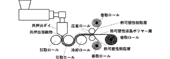
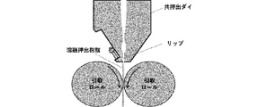
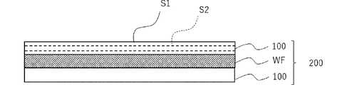
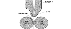
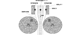
- FIG. 1 It is a figure which shows the co-extrusion method of the LCP extrusion film for stretching process of another aspect. It is a schematic cross-sectional view which shows the insulating material for a circuit board of another aspect. It is a schematic cross-sectional view which shows the metal foil-covered laminated board of another aspect. It is a schematic cross-sectional view which shows the metal foil-covered laminated board of another aspect.
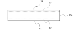
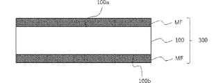
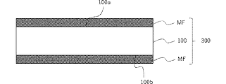
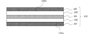
- FIG. 1 is a schematic cross-sectional view showing a main part of the LCP extruded film 100 of one embodiment of the present embodiment
- FIG. 2 is a schematic cross-sectional view showing a main part of the LCP extruded film 100 of another embodiment of the present embodiment.
- the LCP extruded film 100 of each aspect of the present embodiment is obtained by extruding a resin composition containing a thermoplastic liquid crystal polymer into a film having a thickness of 15 ⁇ m or more and 300 ⁇ m or less, and the following conditions (A) and / or (B). ) Satisfies.
- the included degree of orientation ⁇ 2 (%) satisfies the relationship of -4.0 ⁇ [( ⁇ 2- ⁇ 1) / ⁇ 1] ⁇ 100 ⁇ 0.0, and is measured by the TMA method based on JIS K7197 from 23 to 23.
- the coefficient of linear expansion in the MD direction and the TD direction at 200 ° C. is in the range of ⁇ 30 to 55 ppm / K.
- the hardness H1 at a depth of 1 ⁇ m located 1 ⁇ m in the thickness direction from the film surface and the hardness H2 at the center of thickness measured by the nanoindentation method with respect to the film cross section parallel to the MD direction are ⁇ .
- thermoplastic liquid crystal polymer is extremely molecular on the film surface, such as peeling of the skin layer and peeling of fibrillated fibers on the film surface (film surface S1). It was oriented. It is presumed that this is because the thermoplastic liquid crystal polymer is highly oriented on the surface of the extruded body as a result of receiving shear stress from the side surface of the device during extrusion. Then, it was confirmed that the extreme molecular orientation of the thermoplastic liquid crystal polymer on the film surface was relaxed by the improvement as in Patent Documents 1 and 2, but at the same time, the molecule of the thermoplastic liquid crystal polymer on the film surface was confirmed.
- the LCP extruded film 100 of each embodiment of the present embodiment is different from the prior art in that the molecular orientation and internal strain of the thermoplastic liquid crystal polymer are formed not only on the film surface (film surface S1) but also on the inside of the film (film surface S2). Etc. are alleviated, and as a result, the anisotropy of the dimensional change rate is significantly reduced as compared with the conventional case.
- the LCP extruded film 100 of one aspect of the present embodiment shown in FIG. 1 has at least an orientation degree ⁇ 1 (%) including an exposed film surface S1 and an etching treatment of the film surface S1 in the thickness direction.
- the degree of orientation ⁇ 2 (%) including the film surface S2 located at a depth of 5 ⁇ m from the exposed film surface S1 satisfies the relationship of -4.0 ⁇ [( ⁇ 2- ⁇ 1) / ⁇ 1] ⁇ 100 ⁇ 0.0.
- the linear expansion coefficient in the MD direction and the TD direction at 23 to 200 ° C. measured by the TMA method based on JIS K7197 is in the range of -30 to 55 ppm / K.
- the LCP extruded film 100 of another embodiment shown in FIG. 2 has a depth located at least 1 ⁇ m in the thickness direction from the film surface as measured by the nanoindentation method with respect to the film cross section parallel to the MD direction.
- the hardness H1 at the 1 ⁇ m point and the hardness H2 at the center of thickness satisfy -10.0 ⁇ 100 ⁇ (H2-H1) / H1 ⁇ 0.0, and are measured by the TMA method compliant with JIS K7197.
- the linear expansion coefficient in the MD direction and the TD direction at 23 to 200 ° C. is in the range of ⁇ 30 to 55 ppm / K.
- the LCP extruded film 100 an extruded film such as a T-die extruded film is preferably used.
- the LCP extruded film 100 is an intermediate layer (core layer) of a three-layer coextruded film having a laminated structure in which a thermoplastic resin layer, a thermoplastic liquid crystal polymer layer, and a thermoplastic resin layer are arranged at least in this order.
- a thermoplastic liquid crystal polymer layer is also preferably used.
- Extruded films of thermoplastic liquid crystal polymers can be produced at low cost and homogeneously as compared with woven fabrics and non-woven fabrics made of fibers of thermoplastic liquid crystal polymers.
- thermoplastic liquid crystal polymer contained in the LCP extruded film 100 those known in the art can be used, and the type thereof is not particularly limited.
- the liquid crystal polymer is a polymer that forms an optically anisotropic molten phase, and examples thereof include thermotropic liquid crystal compounds.
- the properties of the anisotropic molten phase can be confirmed by a known method such as a polarization inspection method using an orthogonal polarizing element. More specifically, the confirmation of the anisotropic molten phase can be carried out by observing the sample placed on the Leitz hot stage at a magnification of 40 times under a nitrogen atmosphere using a Leitz polarizing microscope.
- thermoplastic liquid crystal polymer examples include a single amount of an aromatic or aliphatic dihydroxy compound, an aromatic or aliphatic dicarboxylic acid, an aromatic hydroxycarboxylic acid, an aromatic diamine, an aromatic hydroxyamine, an aromatic aminocarboxylic acid and the like. Examples thereof include those obtained by polycondensing the body, but the present invention is not particularly limited thereto.
- the thermoplastic liquid crystal polymer is preferably a copolymer. Specifically, an aromatic polyamide resin obtained by polycondensing monomers such as aromatic hydroxycarboxylic acid, aromatic diamine, and aromatic hydroxyamine; aromatic diol, aromatic carboxylic acid, aromatic hydroxycarboxylic acid, and the like. (Whole) aromatic polyester resin obtained by polycondensing the monomers of the above; and the like; but are not particularly limited thereto. These can be used alone or in any combination and ratio of two or more.
- Thermoplastic liquid crystal polymers are generally classified into type I, type II, type III, etc. from the viewpoint of heat distortion temperature (TDUL).
- the LCP extruded film 100 of the present embodiment can be suitably used regardless of the type of thermoplastic liquid crystal polymer, and may be appropriately selected and used according to the application application.
- a type II thermoplastic liquid crystal polymer having a relatively high heat resistance is preferably used.
- (all) aromatic polyester resins having a thermotropic-type liquid crystal-like property and a melting point of 250 ° C. or higher, preferably a melting point of 280 ° C. to 380 ° C. are preferably used.
- an (whole) aromatic polyester resin for example, a (whole) aromatic polyester resin that exhibits liquidity when melted, which is synthesized from a monomer such as an aromatic diol, an aromatic carboxylic acid, or a hydroxycarboxylic acid, is known. Has been done.
- Typical examples are a polycondensate of ethylene terephthalate and parahydroxybenzoic acid, a polycondensate of phenol and phthalic acid with parahydroxybenzoic acid, and 2,6-hydroxynaphthoic acid and parahydroxybenzoic acid. Examples thereof include polycondensates, but the present invention is not particularly limited thereto.
- the (all) aromatic polyester resin one kind may be used alone, or two or more kinds may be used in any combination and ratio. Depending on the required performance, an all-aromatic polyester resin having a relatively high melting point or high thermal deformation temperature and high heat resistance may be used, or an aromatic polyester having a relatively low melting point or low thermal deformation temperature and excellent molding processability. Resin can be used.
- 6-hydroxy-2-naphthoic acid and a derivative thereof are used as a basic structure, and parahydroxybenzoic acid, terephthalic acid, isophthalic acid, and the like.
- One or more selected from the group consisting of 6-naphthalenedicarboxylic acid, 4,4'-biphenol, bisphenol A, hydroquinone, 4,4-dihydroxybiphenol, ethylene terephthalate and derivatives thereof is a monomer component (hereinafter, simply " It may be referred to as “monomer component B”), and examples thereof include (all) aromatic polyester resins having at least.
- the linear lines of molecules are regularly arranged in a molten state to form an anisotropic molten phase, which typically exhibits thermotropic type liquid crystal-like properties, and has mechanical properties. It has excellent basic performance in electrical characteristics, high frequency characteristics, heat resistance, moisture absorption, and the like.
- the (all) aromatic polyester resin of the preferred embodiment described above can have any configuration as long as it has a monomer component A and a monomer component B as essential units. For example, it may have two or more kinds of monomer components A or may have three or more kinds of monomer components A. Further, the (all) aromatic polyester resin of the preferred embodiment described above contains other monomer components (hereinafter, may be simply referred to as “monomer component C”) other than the monomer component A and the monomer component B. You may be doing it.
- the (all) aromatic polyester resin of the above-mentioned preferred embodiment is a polycondensate having a binary system or more composed of only the monomer component A and the monomer component B, the monomer component A, the monomer component B, and the monomer component It may be a polycondensate of a monomer component of a ternary system or more composed of C.
- Other monomer components include those other than the above-mentioned monomer component A and monomer component B, specifically, aromatic or aliphatic dihydroxy compounds and derivatives thereof; aromatic or aliphatic dicarboxylic acids and derivatives thereof; aromatic hydroxycarboxylic acids.
- the other monomer components one kind may be used alone, or two or more kinds may be used in any combination and ratio.
- the "derivative” is a halogen atom (for example, a fluorine atom, a chlorine atom, a bromine atom, an iodine atom) and an alkyl group having 1 to 5 carbon atoms (for example, methyl) as a part of the above-mentioned monomer component.
- a halogen atom for example, a fluorine atom, a chlorine atom, a bromine atom, an iodine atom
- an alkyl group having 1 to 5 carbon atoms for example, methyl
- the "derivative” may be an ester-forming monomer such as an acylated product, an ester derivative, or an acid halide of the monomer components A and B which may have the above-mentioned modifying group.
- thermoplastic liquid crystal polymer using these can be obtained at the time of thermocompression bonding to an adherend. It has excellent moldability.
- the melting point of the (all) aromatic polyester resin is lowered to improve the molding processability when the LCP extruded film 100 is heat-bonded to the adherend, or the peel strength is high when the LCP extruded film 100 is heat-bonded to the metal foil.
- the content ratio of the monomer component A to the (total) aromatic polyester resin in terms of molar ratio is preferably 10 mol% or more and 90 mol% or less, more preferably 30 mol% or more and 85 mol% or less. More preferably, it is 50 mol% or more and 80 mol% or less.
- the content ratio of the monomer component B to the (total) aromatic polyester resin in terms of molar ratio is preferably 10 mol% or more and 90 mol% or less, more preferably 15 mol% or more and 70 mol% or less, and more preferably 20 mol% or more. More preferably, it is 50 mol% or less.
- the content ratio of the monomer component C which may be contained in the (total) aromatic polyester resin is preferably 10 mol% or less, more preferably 8 mol% or less, still more preferably 5 mol% or less in terms of molar ratio. Particularly preferably, it is 3 mol% or less.
- a known method can be applied to the method for synthesizing the (all) aromatic polyester resin, and the method is not particularly limited.
- a known polycondensation method for forming an ester bond with the above-mentioned monomer components for example, a melt polymerization method, a melt acidlysis method, a slurry polymerization method, or the like can be applied.
- an acylation or acetylation step may be performed according to a conventional method.
- the LCP extruded film 100 may further contain an inorganic filler.
- an LCP extruded film 100 having a reduced coefficient of linear expansion can be realized. Specifically, linear expansion in the MD direction, the TD direction, and the ZD direction (Z-axis Direction; film thickness direction). It is easy to obtain an LCP extruded film 100 having reduced coefficient anisotropy.
- Such an LCP extruded film 100 is particularly useful, for example, in rigid substrate applications where multi-layer lamination is required.
- inorganic filler those known in the art can be used, and the type thereof is not particularly limited.
- silica eg natural silica, molten silica, amorphous silica, hollow silica, wet silica, synthetic silica, aerozinc, etc.
- aluminum compounds eg boehmite, aluminum hydroxide, alumina, etc.
- Hydrotalcite aluminum borate, aluminum nitride, etc.
- magnesium compounds eg, magnesium aluminometasilicate, magnesium carbonate, magnesium oxide, magnesium hydroxide, etc.
- calcium compounds eg, calcium carbonate, calcium hydroxide, calcium sulfate, etc.
- molybdenum compounds eg, molybdenum oxide, zinc molybdate, etc.
- talc eg, natural talc, calcine
- the inorganic filler used here may be one that has been subjected to a surface treatment known in the art.
- the surface treatment can improve moisture resistance, adhesive strength, dispersibility and the like.
- the surface treatment agent include, but are not limited to, a silane coupling agent, a titanate coupling agent, a sulfonic acid ester, a carboxylic acid ester, and a phosphoric acid ester.
- the median diameter (d50) of the inorganic filler can be appropriately set according to the required performance and is not particularly limited.
- the d50 of the inorganic filler is preferably 0.01 ⁇ m or more and 50 ⁇ m or less, more preferably 0.03 ⁇ m or more and 50 ⁇ m or less, and further preferably 0. It is 1 ⁇ m or more and 50 ⁇ m or less.
- the median diameter (d50) of the inorganic filler is measured on a volume basis by a laser diffraction / scattering method using a laser diffraction / scattering type particle size distribution measuring device (LA-500 manufactured by HORIBA, Ltd.). Means the value to be.
- the content of the inorganic filler can be appropriately set according to the required performance in consideration of the blending balance with other essential components and optional components, and is not particularly limited. From the viewpoint of kneadability and handleability at the time of preparation, the effect of reducing the coefficient of linear expansion, etc., the content of the inorganic filler is 1% by mass or more and 45% by mass or less in total in terms of solid content with respect to the total amount of the LCP extruded film 100. It is preferable, more preferably 3% by mass or more and 40% by mass or less in total, and further preferably 5% by mass or more and 35% by mass or less in total.
- the LCP extruded film 100 is a resin component other than the above-mentioned thermoplastic liquid crystal polymer (hereinafter, may be simply referred to as “other resin component”), for example, thermosetting, as long as the effect of the present invention is not excessively impaired. It may contain a sex resin, a thermoplastic resin, or the like. Further, the LCP extruded film 100 is an additive known in the art, for example, a higher fatty acid having 10 to 25 carbon atoms, a higher fatty acid ester, a higher fatty acid amide, or a higher fatty acid metal salt, as long as the effect of the present invention is not excessively impaired.
- Polysiloxane, Fluororesin and other mold release improvers; Dyes, pigments and other colorants; Organic fillers; Antioxidants; Heat stabilizers; Light stabilizers; UV absorbers; Flame retardants; Antistatic agents; Surfactants Agent; rust preventive agent; antifoaming agent; fluorescent agent and the like may be contained.
- Each of these additives may be used alone or in combination of two or more.
- These additives can be included in the molten resin composition prepared at the time of molding the LCP extruded film 100.
- the contents of these resin components and additives are not particularly limited, but are preferably 0.01 to 10% by mass, respectively, with respect to the total amount of the LCP extruded film 100 from the viewpoint of moldability, thermal stability, and the like. It is preferably 0.1 to 7% by mass, more preferably 0.5 to 5% by mass, respectively.
- the thickness of the LCP extruded film 100 can be appropriately set according to the requirements and is not particularly limited. Considering the handleability and productivity at the time of extrusion molding, it is preferably 15 ⁇ m or more and 300 ⁇ m or less, more preferably 18 ⁇ m or more and 250 ⁇ m or less, and further preferably 20 ⁇ m or more and 200 ⁇ m or less.
- the LCP extruded film 100 of the present embodiment is not particularly limited as long as it satisfies the above-mentioned conditions (A) and / or (B). That is, the LCP extruded film 100 of the present embodiment may satisfy only the above-mentioned condition (A) or only the above-mentioned condition (B), and the above-mentioned conditions (A) and (B) may be satisfied. Both may be satisfied. Among these, those satisfying both the above-mentioned conditions (A) and (B) are preferable.
- the LCP extruded film 100 satisfying the above-mentioned condition (A) alleviates the molecular orientation and internal strain of the thermoplastic liquid crystal polymer not only on the film surface (film surface S1) but also on the inside of the film (film surface S2).
- the degree of orientation ⁇ 1 including the film surface S1 and the degree of orientation ⁇ 2 including the film surface S2 are adjusted so as to satisfy the following relationship. It is preferably -4.0 ⁇ [( ⁇ 2- ⁇ 1) / ⁇ 1] ⁇ 100 ⁇ 0.0. More preferably, ⁇ 3.0 ⁇ [( ⁇ 2- ⁇ 1) / ⁇ 1] ⁇ 100 ⁇ 0.0. More preferably, ⁇ 2.0 ⁇ [( ⁇ 2- ⁇ 1) / ⁇ 1] ⁇ 100 ⁇ 0.0.
- the film surface S1 is the outermost surface of the LCP extruded film 100 of the present embodiment, and is an exposed surface exposed outward.
- the degree of orientation including the film surface S1 (degree of orientation ⁇ 1) is preferably 39.0% or less, more preferably 38.5% or less, still more preferably 38.0% or less.
- the film surface S2 is a surface newly exposed by etching the film surface S1 of the LCP extruded film 100 of the present embodiment in the thickness direction, and in FIG. 1, a virtual surface located at a depth of 5 ⁇ m from the film surface S1. It is represented by a broken line as a surface.
- the degree of orientation including the film surface S2 (degree of orientation ⁇ 2) is preferably 37.7% or less, more preferably 37.5% or less, still more preferably 37.3% or less. Further, the depth at which the film surface S2 is located does not have to be exactly 5 ⁇ m from the film surface S1 in consideration of dissolution error during etching, and may be 5.0 ⁇ m or more from the film surface S1. Further, the etching treatment conditions for producing the film surface S2 are not particularly limited, but from the viewpoint of ensuring the objectivity between the measurement data, the conditions described in Examples described later shall be followed.
- the orientation degrees ⁇ 1 and ⁇ 2 (%) including the film surfaces S1 and S2 of the LCP extruded film 100 are subjected to X-ray diffraction measurement by a transmission method using an X-ray diffractometer, and the obtained diffraction is obtained. It means a value calculated from the following formula based on the area ratio of the orientation peak in the intensity distribution curve.
- a measurement target with a small degree of orientation (%) a broad diffraction peak with a small peak intensity is observed in X-ray diffraction measurement, so a calculation method based on the half-value width of the orientation peak has high measurement accuracy. Cannot be guaranteed.
- the degree of orientation ⁇ 1 and ⁇ 2 (%) including the film surfaces S1 and S2 are calculated by a calculation method based on the area ratio of the orientation peak instead of the half width of the orientation peak.
- the peak intensity (orientation component) is measured by the 2 ⁇ / ⁇ scan
- the orientation angle direction is measured by the ⁇ scan.
- the area occupied by the oriental component excluding the area of the base isotropic component by measuring the intensity from 0 ° to 360 ° to obtain the intensity distribution in the azimuth angle direction (base strength (isotropic component)).
- the LCP extruded film 100 satisfying the above-mentioned condition (B) alleviates the molecular orientation and internal strain of the thermoplastic liquid crystal polymer not only on the surface of the film but also inside the film, and the desired dimensional change rate is anisotropic.
- It is preferably -10.0 ⁇ 100 ⁇ (H2-H1) / H1 ⁇ 0.0. More preferably, it is ⁇ 7.5 ⁇ 100 ⁇ (H2-H1) / H1 ⁇ 0.0. More preferably, it is ⁇ 5.0 ⁇ 100 ⁇ (H2-H1) / H1 ⁇ 0.0.
- Hardness H1 is an index showing the molecular orientation, internal strain, etc. of the thermoplastic liquid crystal polymer in the vicinity of the film surface of the LCP extruded film 100.
- the hardness H1 at a depth of 1 ⁇ m tends to increase as the orientation of the thermoplastic liquid crystal polymer decreases, and tends to decrease as the orientation of the thermoplastic liquid crystal polymer increases.
- the hardness H1 at a depth of 1 ⁇ m is preferably 0.250 GPa or more, more preferably 0.255 GPa or more.
- the hardness H2 of the thickness center point (positions equidistant from one film surface and the other film surface in the plan view of the film cross section) in the film cross section parallel to the MD direction is the inside of the film of the LCP extruded film 100. It is an index showing the molecular orientation, internal strain, etc. of the thermoplastic liquid crystal polymer in the above.
- the hardness H2 at the center of thickness tends to increase as the orientation of the thermoplastic liquid crystal polymer decreases, and tends to decrease as the orientation of the thermoplastic liquid crystal polymer increases.
- the hardness H2 at the center of thickness is preferably 0.240 GPa or more, more preferably 0.245 GPa or more.
- the method for producing the film cross section parallel to the MD direction of the LCP extruded film 100 is not particularly limited, but the LCP extruded film 100 is ion-beam processed under freezing conditions from the viewpoint of ensuring the objectiveness between the measurement data. , A film smooth cross section parallel to the MD direction shall be produced.
- the hardness H1 at the point 1 ⁇ m from the film surface and the hardness H2 at the center point of the thickness shall be measured.
- the hardness H1 and the hardness H2 are calculated from the following formulas based on the maximum load Pmax and the contact projection area A (the area where the indenter and the film cross section contact).
- Hardness (GPa) Pmax / A
- the LCP extruded film 100 of each embodiment of the present embodiment has not only the molecular orientation of the thermoplastic liquid crystal polymer represented by the above-mentioned degree of orientation, but also the thermoplastic liquid crystal represented by the linear expansion coefficient in the MD direction and the TD direction.
- the molecular orientation of the polymer is also sufficiently reduced.
- the molecular orientation of the thermoplastic liquid crystal polymer is slightly aligned by being protected by the thermoplastic resin layers of both outer layers at the time of coextrusion of the three layers.
- thermoplastic liquid crystal polymer film in the MD direction and the TD direction is relaxed.
- the LCP extruded films described in Patent Documents 1 and 2 have a stable linear expansion coefficient of about -20 ppm / K in the MD direction, whereas they are in the TD direction.
- the coefficient of linear expansion exceeds 55 ppm, and sometimes reaches about 100 ppm / K.
- the molecular orientation of the thermoplastic liquid crystal polymer still remains largely in the film as a whole, or the internal strain and the like are large. It is easy to understand that it remains.
- the molecular orientation, internal strain, etc. of the thermoplastic liquid crystal polymer of the LCP extruded film 100 as a whole film are the combination of the degree of orientation including the film surface and the coefficient of linear expansion described above and / or the hardness and line by the nanoindentation method. It is necessary to control by combining with the expansion coefficient.
- the LCP extruded film 100 of the present embodiment has a linear expansion coefficient (CTE, ⁇ 2, 23 to 200 ° C.) in the MD direction and the TD direction in the range of ⁇ 30 to 55 ppm / K.
- the LCP extruded film 100 having a linear expansion coefficient within such a range is in a state where internal strain and the like are sufficiently reduced, and the anisotropy of the dimensional change rate is smaller than that in the case where it is not, and the dimensional change is small. It can be an LCP extruded film with a sufficiently small absolute value of rate.
- the linear expansion coefficient (CTE, ⁇ 2, 23 to 200 ° C.) of the LCP extruded film 100 of the present embodiment in the MD direction is in the range of -30 to 10 ppm / K from the viewpoint of further improving the adhesion to the metal foil. It is preferably in the range of -25 to 5 ppm / K, more preferably in the range of -20 to 0 ppm / K, and even more preferably in the range of -20 to 0 ppm / K. Further, the linear expansion coefficient (CTE, ⁇ 2, 23 to 200 ° C.) of the LCP extruded film 100 of the present embodiment in the TD direction is 0 to 55 ppm / K from the viewpoint of further improving the adhesion to the metal foil.
- the coefficient of linear expansion means a value in a temperature interval of 23 to 200 ° C. measured by the TMA method based on JIS K7197.
- other detailed measurement conditions shall be in accordance with the conditions described in Examples described later.
- the coefficient of linear expansion is measured by the TMA method based on JIS K7197, and the average coefficient of linear expansion means the average value of the coefficient of linear expansion at 23 to 200 ° C. measured by the same method. ..
- the coefficient of linear expansion measured here is such that the LCP extruded film 100 is heated at a heating rate of 5 ° C./min (1st heating) and then cooled to the measured ambient temperature (23 ° C.) in order to see the value obtained by eliminating the thermal history. It means the value when (1st cooling) is performed and then the second heating (2nd heating) is performed at a heating rate of 5 ° C./min.
- other detailed measurement conditions shall be in accordance with the conditions described in Examples described later.
- the dielectric property of the LCP extruded film 100 of the present embodiment can be appropriately set according to the desired performance and is not particularly limited.
- the relative permittivity ⁇ r (36 GHz) is preferably 3.0 or more and 3.7 or less, and more preferably 3.0 to 3.5.
- the dielectric loss tangent tan ⁇ (36 GHz) is preferably 0.0010 or more and 0.0050 or less, and more preferably 0.0010 or more and 0.0045 or less.
- the relative permittivity ⁇ r (36 GHz) and the dielectric loss tangent tan ⁇ (36 GHz) mean the values at 36 GHz measured by the cavity resonator contact method according to JIS K6471.
- other detailed measurement conditions shall be in accordance with the conditions described in Examples described later.
- the LCP extruded film 100 of each embodiment of the present embodiment is obtained by extruding a resin composition containing the above-mentioned thermoplastic liquid crystal polymer and, if necessary, an optional component such as an inorganic filler and other resin components to a predetermined thickness.
- a resin composition containing the above-mentioned thermoplastic liquid crystal polymer and, if necessary, an optional component such as an inorganic filler and other resin components to a predetermined thickness.
- various known methods can be applied, and the type thereof is not particularly limited.
- a T-die method or an inflation method for example, a multi-manifold co-extrusion method or a feed block co-extrusion method; for example, a multi-layer co-extrusion method such as a two-layer co-extrusion method or a three-layer co-extrusion method; can do.
- the above-mentioned resin composition is used as T. It is extruded from the T-die by an extrusion molding method using a die (hereinafter, may be simply referred to as "T-die extrusion method") to form a film, and then cooled, crimped, and pressed as necessary. A method of obtaining a predetermined LCP extruded film 100 by heat treatment or the like can be mentioned.
- the resin composition A for the first surface layer containing the thermoplastic resin, the resin composition B for the intermediate layer containing the thermoplastic liquid crystal polymer, and the resin composition C for the second surface layer containing the thermoplastic resin. are prepared, and these are co-extruded from the co-extrusion die of the extruder to extrude the co-extruded melt having a three-layer structure to form the LCP extruded film 100 as the thermoplastic liquid crystal polymer layer of the intermediate layer.
- the extrusion method is preferable. According to such coextrusion molding, the molecular orientation of the thermoplastic liquid crystal polymer in the thermoplastic liquid crystal polymer layer of the intermediate layer is relaxed by being protected by the thermoplastic resin layers of both outer layers.
- a preferred embodiment of the method for producing the LCP extruded film 100 of the present embodiment will be described in detail.
- FIG. 5 to 7 are views showing a preferred embodiment of the method for producing the LCP extruded film 100 of the present embodiment described above.
- the above-mentioned resin composition B containing the above-mentioned thermoplastic liquid crystal polymer and, if necessary, an optional component such as an inorganic filler and other resin components is melt-extruded into a film from the T-die of the extruder.
- the first outer layer (peeling layer) containing the thermoplastic resin and the thermoplastic liquid crystal polymer can be obtained.
- a coextruded melt (three-layer laminated film) having a predetermined thickness and having an intermediate layer (LCP layer) containing the mixture and a second outer layer (release layer) containing the thermoplastic resin is produced.
- the coextruded melt is drawn out on a take-up roll and sent to a cooling roll and a crimping roll. After that, the first outer layer and the second outer layer are peeled off from the intermediate layer, and the thermoplastic resin layer of both outer layers and the thermoplastic liquid crystal polymer layer (LCP extruded film 100) of the intermediate layer are respectively wound on the take-up roll. ..
- the preparation of the resin composition B containing the above-mentioned thermoplastic liquid crystal polymer may be carried out according to a conventional method, and is not particularly limited.
- Each of the above-mentioned components can be manufactured and processed by a known method such as kneading, melt kneading, granulation, extrusion molding, pressing or injection molding.
- a kneading device such as a generally used uniaxial or biaxial extruder or various kneaders can be used.
- a liquid crystal polymer, other resin components, inorganic fillers, additives and the like may be dry-blended in advance using a mixing device such as a tumbler or a Henschel mixer.
- the cylinder set temperature of the kneading device may be appropriately set and is not particularly limited, but is generally preferably in the range of the melting point of the liquid crystal polymer or higher and 360 ° C. or lower, and more preferably the melting point of the liquid crystal polymer + 10 ° C. or higher and 360 ° C. or higher. It is below ° C.
- the resin compositions A and C containing the thermoplastic resin may also be prepared according to a conventional method, and are not particularly limited.
- the thermoplastic resin include polyethylene, polypropylene, polymethylpentene, polyolefin resins such as ethylene- ⁇ -olefin copolymers, acrylic resins such as PMMA, polyamide resins, and acrylonitrile-butadiene-styrene copolymers (ABS). Resin), polystyrene (PS), polyvinyl chloride, polybutylene terephthalate (PBT), polyethylene terephthalate (PET), polycarbonate (PC), polyether ether ketone (PEEK), polyphenyl sulfide (PPS) and the like.
- thermoplastic resins may be blended with other resin components which may be contained in the above-mentioned LCP extruded film 100 or optional components such as an inorganic filler.
- the resin composition A and the resin composition C may have the same resin composition or different resin compositions, and may have different thermoplastic properties even if they contain the same thermoplastic resin. It may contain a resin.
- the resin composition containing the thermoplastic resin can be produced and processed by a known method such as kneading, melt kneading, granulation, extrusion molding, pressing or injection molding.
- a kneading device such as a generally used uniaxial or biaxial extruder or various kneaders can be used.
- the thermoplastic resin, other resin components, inorganic fillers, additives and the like may be dry-blended in advance using a mixing device such as a tumbler or a Henshell mixer.
- the cylinder set temperature of the kneading device may be appropriately set at a temperature or lower at which the thermoplastic resin does not deteriorate due to thermal decomposition, and is not particularly limited.
- the melting point of the thermoplastic resin is + 10 ° C or higher.
- the setting conditions for coextrusion may be appropriately set according to the type and composition of the resin composition to be used, the desired performance of the target extruded film, and the like, and are not particularly limited.
- the set temperature of the cylinder of the extruder may be appropriately set according to the type and composition of the resin composition to be used, the desired performance of the desired extruded film, and the like, and is not particularly limited, but is preferably 230 to 360 ° C. More preferably, it is 280 to 350 ° C.
- the die width (mm) of the T die may be appropriately set according to the type and composition of the resin composition to be used, the desired performance of the desired extruded film, and the like, and is not particularly limited, but is general.
- the thickness is preferably 200 to 2000 mm, more preferably 400 to 1500 mm.
- the lip opening (mm) of the T-die may be appropriately set according to the type and composition of the resin composition to be used, the desired performance of the desired extruded film, and the like, and is not particularly limited, but is generally used. It is preferably 0.1 to 3.0 (mm), more preferably 0.2 to 2.0 (mm).
- the shear rate (sec -1 ) of the lip wall surface of the T-die may be appropriately set according to the type and composition of the resin composition to be used, the desired performance of the desired extruded film, and the like, and is particularly limited. However, it is generally preferably 100 to 1500 (sec -1 ), more preferably 150 to 1000 (sec -1 ).
- the total discharge amount (mm 3 / sec) of the resin composition of the T-die may be appropriately set according to the type and composition of the resin composition to be used, the desired performance of the target extruded film, and the like. Although not particularly limited, it is generally preferably 500 to 15000 (mm 3 / sec), more preferably 1500 to 10000 (mm 3 / sec).
- the melt viscosity (Pa ⁇ sec) of the thermoplastic liquid crystal polymer may also be appropriately set according to the type and composition of the resin composition to be used, the desired performance of the desired extruded film, and the like, and is not particularly limited. Generally, it is preferably 10 to 300 (Pa ⁇ sec), more preferably 20 to 250 (Pa ⁇ sec).
- the melt viscosity (Pa ⁇ sec) of the thermoplastic liquid crystal polymer conforms to JIS K7199, and uses Capillograph 1D (manufactured by Toyo Seiki Seisakusho Co., Ltd.) to have a cylinder length of 10.00 mm, a cylinder diameter of 1.00 mm, and a barrel diameter. It means a value measured under the condition of 9.55 mm and the condition at the time of manufacturing the LCP extruded film 100 (die temperature and shear rate of the lip wall surface).
- the take-up speed (mm / sec) of the co-extruded film may be appropriately set according to the type and composition of the resin composition to be used, the desired performance of the target extruded film, and the like, and is not particularly limited. Generally, it is preferably 15 to 1000 (mm / sec), more preferably 20 to 500 (mm / sec).
- thermoplastic liquid crystal polymer tends to be highly oriented in the MD direction, and internal strain tends to remain.
- film surface film surface
- the molecular orientation of the thermoplastic liquid crystal polymer tends to be reduced, and internal strain tends to be difficult to remain.
- the shear stress (kPa) during coextrusion is a value expressed by the product of the shear rate (sec -1 ) of the lip wall surface and the melt viscosity (Pa ⁇ sec) of the thermoplastic liquid crystal polymer, and the shear rate is , A value calculated based on the total discharge amount of the resin composition at the time of coextrusion, the die width, and the lip opening degree. Therefore, the shear stress during coextrusion can be controlled by adjusting each of these values.
- the shear stress at the time of coextrusion is preferably 40 kPa or less, more preferably 38 kPa or less, and further preferably 36 kPa or less.
- the lower limit is not particularly limited, but is preferably 5 kPa or more, more preferably 10 kPa or more, in consideration of productivity and the like.
- thermoplastic liquid crystal polymer in the MD direction during coextrusion
- drawdown ratio during coextrusion is low.
- the thermoplastic liquid crystal polymer tends to be highly oriented in the MD direction, and internal strain tends to remain.
- drawdown ratio during coextrusion is small, the film surface ( The molecular orientation of the thermoplastic liquid crystal polymer is likely to be reduced on both the film surface S1) and the film interior (film surface S2), and internal strain is unlikely to remain.
- the drawdown ratio is a value expressed by the take-up speed (mm / sec) / the flow rate of the thermoplastic liquid crystal polymer (mm / sec), and the flow rate of the thermoplastic liquid crystal polymer is the flow rate of the resin composition at the time of coextrusion. It is a value calculated based on the total discharge amount, the die width, and the lip opening. Therefore, the drawdown ratio during coextrusion can be controlled by adjusting each of these values.
- the drawdown ratio at the time of coextrusion is preferably 3.5 or less, more preferably 3.3 or less, still more preferably 3.1 or less.
- the lower limit is not particularly limited, but is preferably 1.0 or more, more preferably 1.2 or more, in consideration of productivity and the like.
- the thickness of the obtained LCP extruded film 100 can be appropriately set according to the requirements and is not particularly limited. Considering the handleability and productivity at the time of extrusion molding, it is preferably 15 ⁇ m or more and 300 ⁇ m or less, more preferably 18 ⁇ m or more and 250 ⁇ m or less, and further preferably 20 ⁇ m or more and 200 ⁇ m or less.
- the melting point (melting temperature) of the obtained LCP extruded film 100 is not particularly limited, but from the viewpoint of heat resistance and processability of the film, the melting point (melting temperature) is preferably 200 to 400 ° C., particularly a metal foil. From the viewpoint of enhancing the heat pressure-bonding property to the metal, the temperature is preferably 250 to 360 ° C, more preferably 260 to 355 ° C, still more preferably 270 to 350 ° C, and particularly preferably 275 to 345 ° C.
- the melting point of the LCP extruded film 100 is a DSC8500 (manufactured by PerkinElmer), and the extruded film is heated at 20 ° C./min in a temperature interval of 30 to 400 ° C. in order to see the value obtained by eliminating the thermal history.
- DSC scanning calorimetry
- the extruded LCP extruded film 100 can be used as it is, but the molecular orientation (anisity) of the thermoplastic liquid crystal polymer is further reduced by further performing a pressure heating step as necessary. Alternatively, the internal strain can be further released, whereby the LCP extruded film 100 in which the anisotropy of the dimensional change rate is further reduced and the LCP extruded film 100 in which the absolute value of the dimensional change rate is smaller can be realized. ..
- the heat and pressure treatment may be performed by a method known in the art, for example, a contact type heat treatment, a non-contact heat treatment, or the like, and the type thereof is not particularly limited.
- heat can be set by using known equipment such as a non-contact heater, an oven, a blow device, a heat roll, a cooling roll, a heat press machine, and a double belt heat press machine.
- a release film or a porous film known in the art can be arranged on the surface of the LCP extruded film 100 to perform heat treatment.
- thermocompression bonding is performed while sandwiching it between endless belt pairs of a double belt press machine.
- a thermocompression forming method for removing the release film or the porous film is preferably used.
- the thermal pressure molding method may be performed with reference to, for example, Japanese Patent Application Laid-Open No. 2010-2216994.
- the processing temperature when the LCP extrusion film 100 using the above resin composition is hot-press formed between the endless belt pairs of the double belt press machine is a liquid crystal polymer in order to control the crystal state of the LCP extrusion film 100.
- the temperature is preferably higher than the melting point and 70 ° C. higher than the melting point, more preferably + 5 ° C. higher than the melting point, 60 ° C. higher than the melting point, still more preferably + 10 ° C. higher than the melting point, and the melting point.
- the temperature is 50 ° C. higher or lower.
- the thermocompression bonding conditions at this time can be appropriately set according to the desired performance, and are not particularly limited, but are preferably performed under the conditions of a surface pressure of 0.5 to 10 MPa and a heating temperature of 250 to 430 ° C., more preferably.
- a non-contact heater or an oven it is preferable to carry out the operation at 200 to 320 ° C. for 1 to 20 hours, for example.
- the insulating material 200 for a circuit board of the present embodiment includes an LCP extruded film 100 satisfying the above conditions (A) and / or (B) and a woven fabric WF provided on one side and / or both sides of the LCP extruded film 100. It is provided with at least a laminate having.
- the insulating material 200 for a circuit board includes a laminated body having a laminated structure (three-layer structure) in which the LCP extruded film 100, the woven fabric WF, and the LCP extruded film 100 are arranged at least in this order. ..
- this laminated body one LCP extruded film 100 is provided on the front surface side of the woven fabric WF, and the other LCP extruded film 100 is provided on the back surface side of the woven fabric WF.
- These three layers are thermocompression bonded to form a three-layer structure laminate.
- the present invention further laminates the LCP extrusion film 100 and the woven fabric WF even if the two-layer structure laminate omits one of the LCP extrusion films 100. Needless to say, it is possible to carry out even a laminated body having a laminated structure of four or more layers.
- the woven fabric WF is provided on one side and / or both sides of the LCP extruded film 100
- the LCP extruded film 100 is directly placed on the surface of the woven fabric WF as in the present embodiment.
- the LCP extruded film 100 is separated from the woven fabric WF by an arbitrary layer (for example, a primer layer, an adhesive layer, etc.) (for example, a primer layer, an adhesive layer, etc.) not shown between the LCP extruded film 100 and the woven fabric WF. It is meant to include the arranged aspects.
- Woven cloth WF is a cloth woven with fibers.
- the type of fiber of the woven fabric WF is not particularly limited, and any of inorganic fiber, organic fiber, and organic-inorganic hybrid fiber can be used.
- an inorganic fiber woven fabric WF is preferably used.
- thermocompression bonding the woven fabric WF of the inorganic fiber to the LCP extruded film 100 the anisotropy of the dimensional change rate in the MD direction and the TD direction can be kept small, and in a more preferable embodiment, the dimensional change rate in the MD direction and the TD direction. It can be made smaller.
- As the woven fabric WF a commercially available product can be used, and the woven fabric WF can be manufactured by a method known in the art.
- the inorganic fiber examples include glass fibers such as E glass, D glass, L glass, M glass, S glass, T glass, Q glass, UN glass, NE glass and spherical glass, and inorganic fibers other than glass such as quartz.
- examples thereof include ceramic fibers such as silica, but the present invention is not particularly limited thereto.
- the woven fabric of inorganic fibers a woven fabric that has been subjected to a fiber opening treatment or a filling treatment is suitable from the viewpoint of dimensional stability. Among these, glass cloth is preferable from the viewpoint of mechanical strength, dimensional stability, water absorption and the like.
- a glass cloth that has been subjected to a fiber opening treatment or a filling treatment is preferable. Further, glass cloth surface-treated with a silane coupling agent such as epoxy silane treatment and amino silane treatment can also be preferably used.
- the woven fabric WF may be used alone or in combination of two or more.
- the thickness of the woven fabric WF can be appropriately set according to the required performance and is not particularly limited. From the viewpoint of stackability, processability, mechanical strength, etc., it is preferably 10 to 300 ⁇ m, more preferably 10 to 200 ⁇ m, and even more preferably 15 to 180 ⁇ m.
- the total thickness of the insulating material 200 for the circuit board can be appropriately set according to the required performance, and is not particularly limited. From the viewpoint of stackability, processability, mechanical strength, etc., it is preferably 30 to 500 ⁇ m, more preferably 50 to 400 ⁇ m, still more preferably 70 to 300 ⁇ m, and particularly preferably 90 to 250 ⁇ m.
- the circuit board insulating material 200 of the present embodiment has a small anisotropy of the dimensional change rate in the MD direction and the TD direction, and in a more preferable embodiment, the dimensional change in the MD direction and the TD direction.
- the rate itself can be reduced, and moreover, it has excellent dielectric properties in the high frequency range, and has a remarkable effect of being easy to manufacture and excellent in productivity.
- the above-mentioned insulating material 200 for a circuit board can be manufactured by appropriately applying a known manufacturing method, and the manufacturing method is not particularly limited.
- the LCP extruded film 100 and the woven fabric WF are laminated, heated and pressurized, and the LCP extruded film 100 and the woven fabric WF are thermocompression bonded to obtain an insulating material 200 for a circuit board. Can be done.
- the LCP extruded film 100, the woven fabric WF, and the LCP extruded film 100 are laminated in this order to form a laminated body, and the laminated body is heated and pressed while being sandwiched by a press machine, a double belt press machine, or the like.
- thermocompression bonding can be appropriately set according to the required performance and is not particularly limited, but is preferably 200 to 400 ° C, more preferably 250 to 360 ° C, and further preferably 270 to 350 ° C. be.
- the processing temperature at the time of thermocompression bonding is a value measured by the surface temperature of the LCP extruded film 100 of the above-mentioned laminated body.
- the pressurizing conditions at this time can be appropriately set according to the desired performance, and are not particularly limited, but are, for example, at a surface pressure of 0.5 to 10 MPa for 1 to 240 minutes, more preferably a surface pressure of 0.8 to. It takes 1 to 120 minutes at 8 MPa.
- Metal leaf-clad laminate 10 and 11 are schematic cross-sectional views showing a main part of the metal leaf-clad laminate 300 of the present embodiment.
- the metal foil-clad laminate 300 of the present embodiment is a metal foil provided on one side and / or both sides of an LCP extruded film 100 and the LCP extruded film 100 that satisfy the above conditions (A) and / or (B). It is equipped with an MF.
- the metal foil-clad laminate 300 is a double-sided metal foil-clad laminate having a laminated structure (three-layer structure) in which the metal foil MF, the LCP extruded film 100, and the metal foil MF are arranged in at least this order. be. These three layers are thermocompression bonded to form a three-layer structure laminate.
- the double-sided metal foil-clad laminate is shown in the present embodiment, the present invention can also be implemented in an embodiment in which the metal leaf MF is provided only on one surface of the LCP extruded film 100.
- the LCP extruded film 100 and the woven cloth WF are further laminated even in the two-layer structure laminate in which one of the metal foil MFs is omitted. Needless to say, it is possible to carry out even a laminated body having a laminated structure of four or more layers.
- the metal foil-clad laminate 400 of the present embodiment is the LCP extruded film 100 satisfying the above conditions (A) and / or (B), and the above-mentioned woven fabric provided on one side and / or both sides of the LCP extruded film 100. It includes a laminate having at least WF and a metal foil MF provided on one side and / or both sides of the laminate.
- the metal foil-clad laminate 400 has a laminated structure (five-layer structure) in which a metal foil MF, an LCP extruded film 100, a woven cloth WF, an LCP extruded film 100, and a metal foil MF are arranged at least in this order. It is a double-sided metal leaf-covered laminated board having. These five layers are thermocompression bonded to form a five-layer structure laminate.
- the double-sided metal leaf-clad laminate is shown in the present embodiment, the present invention can also be implemented in an embodiment in which the metal leaf MF is provided on only one surface.
- the material of the metal foil MF is not particularly limited, and examples thereof include gold, silver, copper, copper alloys, nickel, nickel alloys, aluminum, aluminum alloys, iron, and iron alloys.
- copper foil, aluminum foil, stainless steel foil, and alloy foil of copper and aluminum are preferable, and copper foil is more preferable.
- the copper foil any one produced by a rolling method, an electrolysis method or the like can be used, but an electrolytic copper foil or a rolled copper foil having a relatively large surface roughness is preferable.
- the thickness of the metal foil MF can be appropriately set according to the desired performance and is not particularly limited. Usually, it is preferably 1.5 to 1000 ⁇ m, more preferably 2 to 500 ⁇ m, still more preferably 5 to 150 ⁇ m, and particularly preferably 7 to 100 ⁇ m.
- the metal leaf MF may be subjected to surface treatment such as chemical surface treatment such as pickling as long as the action and effect of the present invention are not impaired.
- the type and thickness of the metal foil MF may be the same or different.
- the method of providing the metal foil MF on the surface of the LCP extruded film 100 or the insulating material 200 for the circuit board can be performed according to a conventional method, and is not particularly limited.
- a laminate obtained by laminating an LCP extruded film 100 or an insulating material 200 for a circuit board and one or more metal foil MFs is heated by using, for example, a multi-stage press machine, a multi-stage vacuum press machine, a continuous molding machine, an autoclave molding machine, or the like. By pressing, metal foil-clad laminates 300, 400 can also be obtained.
- the above-mentioned metal foil-clad laminates 300 and 400 can be manufactured by appropriately applying a known manufacturing method, and the manufacturing method is not particularly limited.
- the LCP extruded film 100 or the insulating material 200 for a circuit board and the metal leaf MF are superposed to form a laminated body in which the metal foil MF is placed on the LCP extruded film 100, and this laminated body is doubled.
- a method of hot pressure forming while sandwiching between endless belt pairs of a belt press machine can be mentioned.
- the LCP extruded film 100 used in the present embodiment has a small anisotropy of the dimensional change rate in the MD direction and the TD direction, and more preferably, the dimensional change rate itself in the MD direction and the TD direction is small. High peel strength to the metal foil MF can be obtained.
- the temperature at the time of thermal pressure bonding of the metal foil MF can be appropriately set according to the required performance, and is not particularly limited, but is preferably a temperature 50 ° C. lower than the melting point of the liquid crystal polymer and 50 ° C. higher than the melting point.
- a temperature 40 ° C. lower than the melting point and 40 ° C. higher than the melting point is more preferable, a temperature 30 ° C. lower than the melting point and 30 ° C. higher than the melting point is further preferable, and a temperature 20 ° C. lower than the melting point is 20 ° C. or higher. It is particularly preferable that the temperature is 20 ° C. higher than the melting point.
- the temperature at the time of thermocompression bonding of the metal foil MF is a value measured by the surface temperature of the LCP extruded film 100 described above.
- the crimping conditions at this time can be appropriately set according to the desired performance and are not particularly limited. For example, when a double belt press machine is used, the surface pressure is 0.5 to 10 MPa and the heating temperature is 200 to 360 ° C. It is preferable to carry out under the conditions.
- the metal foil-clad laminates 300 and 400 of the present embodiment may have another laminated structure or a further laminated structure as long as the thermocompression bonding body having a two-layer structure of the LCP extruded film 100 and the metal foil MF is provided. ..
- a two-layer structure of a metal foil MF / LCP extruded film 100 for example, a two-layer structure of a metal foil MF / LCP extruded film 100; a three-layer structure such as a metal foil MF / LCP extruded film 100 / metal foil MF, an LCP extruded film 100 / metal foil MF / LCP extruded film 100; / LCP Extruded Film 100 / Woven WF / LCP Extruded Film 100-like 4-layer structure; Metal Foil MF / LCP Extruded Film 100 / Metal Foil MF / LCP Extruded Film 100 / Metal Foil MF, Metal Foil MF / LCP Extruded Film It can have a multi-layer structure such as 100 / woven cloth WF / LCP extruded film 100 / metal foil MF-like five-layer structure; Further, a plurality of (for example, 2 to 50) metal foil-cla
- the peel strength of the LCP extruded film 100 and the metal foil MF is not particularly limited, but is 0.8 (N / mm) from the viewpoint of providing higher peel strength. ) Or more, more preferably 1.0 (N / mm) or more, still more preferably 1.2 (N / mm) or more.
- high peel strength can be realized, so that peeling between the LCP extruded film 100 and the metal leaf MF can be suppressed, for example, in the heating process of substrate manufacturing.
- manufacturing conditions with excellent process margin and productivity can be applied to obtain the same peel strength as the conventional technique, the basic performance of the liquid crystal polymer deteriorates while maintaining the same level of peel strength as the conventional technique. Can be suppressed.
- the metal foil-clad laminates 300 and 400 of the present embodiment can be used as a material for a circuit board such as an electronic circuit board or a multilayer board by pattern etching at least a part of the metal foil MF. Further, the metal foil-clad laminates 300 and 400 of the present embodiment are excellent in dielectric properties in the high frequency region, have small dimensional change rate anisotropy in the MD direction and the TD direction, and in a more preferable embodiment, the MD direction and the TD. Insulation material such as flexible printed wiring board (FPC) in 5th generation mobile communication system (5G) and millimeter wave radar because the dimensional change rate itself in the direction is small, dimensional stability is excellent, manufacturing is easy and productivity is excellent. It is a particularly useful material.
- FPC flexible printed wiring board
- 5G 5th generation mobile communication system
- millimeter wave radar because the dimensional change rate itself in the direction is small, dimensional stability is excellent, manufacturing is easy and productivity is excellent. It is a particularly useful material.
- the LCP extruded film 100 obtained by extruding a resin composition containing a thermoplastic liquid crystal polymer into a film is used, but if necessary, the LCP extruded film 100 is further added with 1 It can also be used in the form of an LCP stretched film (stretched body of the LCP extruded film 100) after undergoing a shaft and / or biaxial stretching treatment. Then, using this LCP stretched film, the above-mentioned insulating material 200 for a circuit board, metal leaf-clad laminates 300, 400 and the like can be constructed.
- the setting conditions for the stretching treatment may be appropriately set according to the type and composition of the resin composition to be used, the desired performance of the target LCP stretched film, and the like, and are not particularly limited.
- the LCP extruded film 100 can be stretched 1.1 to 2.5 times in the TD direction (Transverse Direction) at 90 to 180 ° C., and then 100 to, for example. It is preferable to perform heat treatment (heat setting) at 240 ° C. for 1 to 600 seconds.
- the LCP extruded film 100 is preferably stretched 1.1 to 2.5 times at 70 to 180 ° C. in the MD direction (Machine Direction) to obtain a uniaxially stretched film.
- the draw ratio is not particularly limited, but from the viewpoints of improving film transportability, releasability, suppressing thickness unevenness, wrinkles, etc., the total draw ratio in the MD direction ⁇ TD direction (the draw ratio in the MD direction is m).
- the stretching ratio expressed in m ⁇ n) is preferably 1.1 times or more, more preferably 1.2 times or more, still more preferably 1.3 times or more. Particularly preferably, it is 1.5 times or more.
- the upper limit thereof is not particularly limited, but is 3.0 times or less as a guideline, preferably 2.7 times or less, more preferably less than 2.5 times, and particularly preferably less than 2.3 times.
- a method known in the art for example, a contact type heat treatment, a non-contact heat treatment, or the like can be performed, and the type thereof is not particularly limited.
- heat can be set by using known equipment such as a non-contact heater, an oven, a blow device, a heat roll, a cooling roll, a heat press machine, and a double belt heat press machine.
- a release film or a porous film known in the art can be arranged on the surface of the LCP stretched film to perform thermal pressure treatment.
- the linear expansion coefficient (CTE, ⁇ 2, 23 to 200 ° C.) of the LCP extruded film 100 in the MD direction and the TD direction of the LCP stretched film (stretched body of the LCP extruded film 100) can be appropriately set according to the desired performance.
- the anisotropy of the dimensional change rate and the absolute value of the dimensional change rate should be within the range of -20 to 15 ppm / K from the viewpoint of improving the adhesion to the metal foil. Is preferable, each is in the range of -15 to 10 ppm / K, more preferably in the range of -10 to 5 ppm / K, and each in the range of -10 to 0 ppm / K. Is particularly preferable.
- LCP extruded film for stretching treatment LCP extruded film for stretching treatment
- LCP extruded film before stretching treatment LCP extruded film before stretching treatment
- LCP extruded film for stretching treatment LCP extruded film before stretching treatment
- the LCP extruded film for stretching treatment described here is another aspect of the present invention, and is an LCP extruded film (an LCP extruded film to be stretched) that contains a thermoplastic liquid crystal polymer and can be uniformly stretched during the stretching treatment.
- the thermoplastic liquid crystal polymer is extremely molecularly oriented on the film surface, such as peeling of the skin layer and peeling of fibrillated fibers on the film surface.
- the thermoplastic liquid crystal polymer is highly oriented on the surface of the extruded body as a result of receiving shear stress from the side surface of the device during extrusion.
- the LCP stretched film has a small dimensional change rate anisotropy and an absolute value of the dimensional change rate by performing the stretching treatment.
- the LCP extruded film of the prior art has almost no stretchability during the stretching process, and an industrially useful LCP stretched film can be obtained. That turned out to be practically difficult.
- non-uniform stretching occurs even if the stretching treatment is performed in the TD direction at a stretching ratio of 1.1 times, or the stretching ratio in the TD direction is 1.2 times, for example.
- the film was not suitable for stretching, for example, the film was broken when the film was increased to a high value.
- thermoplastic liquid crystal polymer on the film surface was relaxed by the improvement as in Patent Documents 1 and 2, but at the same time, the molecule of the thermoplastic liquid crystal polymer on the film surface was confirmed. It has been found from the findings of the present inventors that it is not possible to realize a material that can withstand the required performance as an insulating material for a circuit board only by controlling the orientation.
- the LCP extruded film for stretching treatment (LCP extruded film to be stretched) of the present embodiment has been studied from this point of view. That is, the stretched LCP extruded film (stretched LCP extruded film) of the present embodiment has good stretchability at least in the TD direction by having predetermined tensile properties, which is difficult in the prior art. Uniform stretching is possible. Then, by stretching the LCP extruded film to be stretched, the molecular orientation and internal strain of the thermoplastic liquid crystal polymer generated on the film surface and / or inside the film are reduced, and thereby the dimensional change rate is different. It is possible to realize a heat-shrinkable LCP stretched film having a small absolute value of property and dimensional change rate.
- thermoplastic liquid crystal polymer contained in the LCP extruded film for stretching treatment those known in the art can be used, and the type thereof is not particularly limited.
- the liquid crystal polymer is a polymer that forms an optically anisotropic molten phase, and examples thereof include thermotropic liquid crystal compounds.
- the properties of the anisotropic molten phase can be confirmed by a known method such as a polarization inspection method using an orthogonal polarizing element. More specifically, the confirmation of the anisotropic molten phase can be carried out by observing the sample placed on the Leitz hot stage at a magnification of 40 times under a nitrogen atmosphere using a Leitz polarizing microscope.
- thermoplastic liquid crystal polymer examples include a single amount of an aromatic or aliphatic dihydroxy compound, an aromatic or aliphatic dicarboxylic acid, an aromatic hydroxycarboxylic acid, an aromatic diamine, an aromatic hydroxyamine, an aromatic aminocarboxylic acid and the like. Examples thereof include those obtained by polycondensing the body, but the present invention is not particularly limited thereto.
- the thermoplastic liquid crystal polymer is preferably a copolymer. Specifically, an aromatic polyamide resin obtained by polycondensing monomers such as aromatic hydroxycarboxylic acid, aromatic diamine, and aromatic hydroxyamine; aromatic diol, aromatic carboxylic acid, aromatic hydroxycarboxylic acid, and the like. (Whole) aromatic polyester resin obtained by polycondensing the monomers of the above; and the like; but are not particularly limited thereto. These can be used alone or in any combination and ratio of two or more.
- Thermoplastic liquid crystal polymers are generally classified into type I, type II, type III, etc. from the viewpoint of heat distortion temperature (TDUL).
- the LCP extruded film for stretching treatment of the present embodiment can be suitably used regardless of the type of thermoplastic liquid crystal polymer, and may be appropriately selected and used according to the application application.
- a type II thermoplastic liquid crystal polymer having a relatively high heat resistance is preferably used.
- (all) aromatic polyester resins having a thermotropic-type liquid crystal-like property and a melting point of 250 ° C. or higher, preferably a melting point of 280 ° C. to 380 ° C. are preferably used.
- an (whole) aromatic polyester resin for example, a (whole) aromatic polyester resin that exhibits liquidity when melted, which is synthesized from a monomer such as an aromatic diol, an aromatic carboxylic acid, or a hydroxycarboxylic acid, is known. Has been done.
- Typical examples are a polycondensate of ethylene terephthalate and parahydroxybenzoic acid, a polycondensate of phenol and phthalic acid with parahydroxybenzoic acid, and 2,6-hydroxynaphthoic acid and parahydroxybenzoic acid. Examples thereof include polycondensates, but the present invention is not particularly limited thereto.
- the (all) aromatic polyester resin one kind may be used alone, or two or more kinds may be used in any combination and ratio. Depending on the required performance, an all-aromatic polyester resin having a relatively high melting point or high thermal deformation temperature and high heat resistance may be used, or an aromatic polyester having a relatively low melting point or low thermal deformation temperature and excellent molding processability. Resin can be used.
- 6-hydroxy-2-naphthoic acid and a derivative thereof are used as a basic structure, and parahydroxybenzoic acid, terephthalic acid, isophthalic acid, and the like.
- One or more selected from the group consisting of 6-naphthalenedicarboxylic acid, 4,4'-biphenol, bisphenol A, hydroquinone, 4,4-dihydroxybiphenol, ethylene terephthalate and derivatives thereof is a monomer component (hereinafter, simply " It may be referred to as “monomer component B”), and examples thereof include (all) aromatic polyester resins having at least.
- the linear lines of molecules are regularly arranged in a molten state to form an anisotropic molten phase, which typically exhibits thermotropic type liquid crystal-like properties, and has mechanical properties. It has excellent basic performance in electrical characteristics, high frequency characteristics, heat resistance, moisture absorption, and the like.
- the (all) aromatic polyester resin of the preferred embodiment described above can have any configuration as long as it has a monomer component A and a monomer component B as essential units. For example, it may have two or more kinds of monomer components A or may have three or more kinds of monomer components A. Further, the (all) aromatic polyester resin of the preferred embodiment described above contains other monomer components (hereinafter, may be simply referred to as “monomer component C”) other than the monomer component A and the monomer component B. You may be doing it.
- the (all) aromatic polyester resin of the above-mentioned preferred embodiment is a polycondensate having a binary system or more composed of only the monomer component A and the monomer component B, the monomer component A, the monomer component B, and the monomer component It may be a polycondensate of a monomer component of a ternary system or more composed of C.
- Other monomer components include those other than the above-mentioned monomer component A and monomer component B, specifically, aromatic or aliphatic dihydroxy compounds and derivatives thereof; aromatic or aliphatic dicarboxylic acids and derivatives thereof; aromatic hydroxycarboxylic acids.
- the other monomer components one kind may be used alone, or two or more kinds may be used in any combination and ratio.
- the "derivative” is a halogen atom (for example, a fluorine atom, a chlorine atom, a bromine atom, an iodine atom) and an alkyl group having 1 to 5 carbon atoms (for example, methyl) as a part of the above-mentioned monomer component.
- a halogen atom for example, a fluorine atom, a chlorine atom, a bromine atom, an iodine atom
- an alkyl group having 1 to 5 carbon atoms for example, methyl
- the "derivative” may be an ester-forming monomer such as an acylated product, an ester derivative, or an acid halide of the monomer components A and B which may have the above-mentioned modifying group.
- thermoplastic liquid crystal polymer using these can be obtained at the time of thermocompression bonding to an adherend. It has excellent moldability.
- the melting point of the (all) aromatic polyester resin is lowered to improve the moldability of the stretched LCP extruded film or its stretched material during thermal pressure bonding to the adherend, or the stretched LCP extruded film or its stretched body.
- the content ratio of the monomer component A to the (total) aromatic polyester resin in terms of molar ratio is preferably 10 mol% or more and 90 mol% or less, from the viewpoint of obtaining high peel strength when the metal foil is thermally pressure-bonded. It is more preferably 30 mol% or more and 85 mol% or less, and further preferably 50 mol% or more and 80 mol% or less.
- the content ratio of the monomer component B to the (total) aromatic polyester resin in terms of molar ratio is preferably 10 mol% or more and 90 mol% or less, more preferably 15 mol% or more and 70 mol% or less, and more preferably 20 mol% or more. More preferably, it is 50 mol% or less.
- the content ratio of the monomer component C which may be contained in the (total) aromatic polyester resin is preferably 10 mol% or less, more preferably 8 mol% or less, still more preferably 5 mol% or less in terms of molar ratio. Particularly preferably, it is 3 mol% or less.
- a known method can be applied to the method for synthesizing the (all) aromatic polyester resin, and the method is not particularly limited.
- a known polycondensation method for forming an ester bond with the above-mentioned monomer components for example, a melt polymerization method, a melt acidlysis method, a slurry polymerization method, or the like can be applied.
- an acylation or acetylation step may be performed according to a conventional method.
- the LCP extruded film for stretching treatment may further contain an inorganic filler.
- an LCP extruded film for stretching treatment having a reduced coefficient of linear expansion can be realized, specifically, in the MD direction, the TD direction, and the ZD direction (Z-axis Direction; film thickness direction). It is easy to obtain an LCP extruded film for stretching treatment in which the anisotropy of the linear expansion coefficient is reduced.
- Such an LCP extruded film for stretching treatment is particularly useful in, for example, a rigid substrate application that requires multi-layer lamination.
- inorganic filler those known in the art can be used, and the type thereof is not particularly limited.
- silica eg natural silica, molten silica, amorphous silica, hollow silica, wet silica, synthetic silica, aerozinc, etc.
- aluminum compounds eg boehmite, aluminum hydroxide, alumina, etc.
- Hydrotalcite aluminum borate, aluminum nitride, etc.
- magnesium compounds eg, magnesium aluminometasilicate, magnesium carbonate, magnesium oxide, magnesium hydroxide, etc.
- calcium compounds eg, calcium carbonate, calcium hydroxide, calcium sulfate, etc.
- molybdenum compounds eg, molybdenum oxide, zinc molybdate, etc.
- talc eg, natural talc, calcine
- the inorganic filler used here may be one that has been subjected to a surface treatment known in the art.
- the surface treatment can improve moisture resistance, adhesive strength, dispersibility and the like.
- the surface treatment agent include, but are not limited to, a silane coupling agent, a titanate coupling agent, a sulfonic acid ester, a carboxylic acid ester, and a phosphoric acid ester.
- the median diameter (d50) of the inorganic filler can be appropriately set according to the required performance and is not particularly limited.
- the d50 of the inorganic filler is preferably 0.01 ⁇ m or more and 50 ⁇ m or less, more preferably 0.03 ⁇ m or more and 50 ⁇ m or less, and further preferably 0. It is 1 ⁇ m or more and 50 ⁇ m or less.
- the median diameter (d50) of the inorganic filler is measured on a volume basis by a laser diffraction / scattering method using a laser diffraction / scattering type particle size distribution measuring device (LA-500 manufactured by HORIBA, Ltd.). Means the value to be.
- the content of the inorganic filler can be appropriately set according to the required performance in consideration of the blending balance with other essential components and optional components, and is not particularly limited.
- the content of the inorganic filler is 1% by mass or more and 45% by mass in total in terms of solid content with respect to the total amount of the LCP extruded film for stretching treatment.
- the following is preferable, more preferably 3% by mass or more and 40% by mass or less in total, and further preferably 5% by mass or more and 35% by mass or less in total.
- the LCP extruded film for stretching treatment is a resin component other than the above-mentioned thermoplastic liquid crystal polymer (hereinafter, may be simply referred to as “other resin component”), for example, as long as the effect of the present invention is not excessively impaired. It may contain a thermosetting resin, a thermoplastic resin, or the like. Further, the LCP extruded film for stretching treatment is an additive known in the art, for example, a higher fatty acid having 10 to 25 carbon atoms, a higher fatty acid ester, a higher fatty acid amide, or a higher fatty acid, as long as the effect of the present invention is not excessively impaired.
- Demolding improver such as metal salt, polysiloxane, fluororesin; colorant such as dye, pigment; organic filler; antioxidant; heat stabilizer; light stabilizer; ultraviolet absorber; flame retardant; antistatic agent; It may contain a surfactant; a rust preventive agent; an antifoaming agent; a fluorescent agent and the like.
- Each of these additives may be used alone or in combination of two or more.
- These additives can be included in the molten resin composition prepared at the time of molding the LCP extruded film for stretching treatment.
- the contents of these resin components and additives are not particularly limited, but are preferably 0.01 to 10% by mass, respectively, with respect to the total amount of the LCP extruded film for stretching treatment from the viewpoint of moldability and thermal stability. , More preferably 0.1 to 7% by mass, and even more preferably 0.5 to 5% by mass, respectively.
- the LCP extruded film for stretching treatment of the present embodiment has predetermined tensile properties, unlike the prior art, it has good stretching suitability at least in the TD direction and can be uniformly stretched during stretching treatment.
- the LCP extruded film for stretching treatment of the present embodiment is described in the stress-strain curve measured in a constant temperature bath tensile test (JIS K7161-1: 2014 compliant, 200 ° C., tensile strength 200 mm / min).
- the yield point strength X (MPa) and the fracture point strength Y (MPa) in the TD direction of the LCP extruded film for stretching treatment satisfy the following formula (I). 0.75 ⁇ fracture point strength Y / yield point strength X ⁇ 1.50 ... (I)
- the test piece is placed at a constant speed along the main axis (constant speed in the direction perpendicular to the cross section of the test piece) until the test piece breaks. It is a pulling test to measure the force and elongation applied to the test piece.
- the yield point strength X means the highest point in the yield region of the stress-strain curve obtained in the above tensile test, and the higher this value is, the stronger the force is required to deform the material. ..
- the fracture point strength Y (MPa) means the stress immediately before the test piece is fractured in the above tensile test, and the higher this value is, the stronger the force is required to fracture the material.
- the fracture point strength Y / yield point strength X means the strength ratio of the fracture point strength Y and the yield point strength X in the stress-strain curve obtained in the tensile test.
- 14 and 15 are graphs showing an example of a stress-strain curve in the TD direction of the LCP extruded film for stretching treatment of the present invention satisfying 0.75 ⁇ Y / X ⁇ 1.50. Further, FIG.
- the LCP extruded film for stretching treatment of the present invention has a relatively large strength ratio of fracture point strength Y / yield point strength X with respect to the prior art. , Has uniform stretchability with a constant load. Further, the displacement amount (horizontal axis) from the yield point strength X to the fracture point strength Y correlates with the draw ratio, and a large displacement amount indicates that a high draw ratio can be applied. .. That is, unlike the prior art, the LCP extruded film for stretching treatment of the present embodiment satisfying the above formula (I) can be stretched relatively uniformly, and a relatively high stretching ratio can be applied. Is understood.
- the value of the fracture point strength Y / yield point strength X in the TD direction is not particularly limited, but is preferably 0.80 or more and 1.50 or less, more preferably 0.85 or more and 1.50 or less, and further preferably. Is 0.90 or more and 1.35 or less, and particularly preferably 0.90 or more and 1.20 or less. The larger this value is, the higher the uniform stretchability in the TD direction tends to be.
- the values of the fracture point strength Y / yield point strength X are the average values when the tensile test is performed 5 times under the conditions described in the examples described later from the viewpoint of ensuring the measurement accuracy. do.
- the value of the breaking point strength Y / yield point strength X in the MD direction is not particularly limited.
- the value of the fracture point strength Y / yield point strength X in the MD direction is preferably 0.75 or more and 1.50 or less, and more preferably 0.80 or more. It is 50 or less, more preferably 0.85 or more and 1.50 or less, and particularly preferably 0.90 or more and 1.50 or less. The larger this value is, the higher the uniform stretchability in the MD direction tends to be.
- the LCP extruded film for stretching treatment a melt extruded film such as a T-die extruded film is preferably used.
- the LCP extruded film for stretching treatment is an intermediate layer (core layer) of a three-layer coextruded film having a laminated structure in which a thermoplastic resin layer, a thermoplastic liquid crystal polymer layer, and a thermoplastic resin layer are arranged at least in this order.
- the thermoplastic liquid crystal polymer layer is also preferably used. In this case, by removing the thermoplastic resin layers on both outer layers of the three-layer coextruded film, it can be used as a single-layer thermoplastic liquid crystal polymer film (LCP extruded film for stretching treatment).
- Extruded films of thermoplastic liquid crystal polymers can be produced at low cost and homogeneously as compared with woven fabrics and non-woven fabrics made of fibers of thermoplastic liquid crystal polymers.
- the thickness of the LCP extruded film for stretching treatment can be appropriately set according to the requirements and is not particularly limited. Considering the handleability and productivity at the time of extrusion molding, it is preferably 15 ⁇ m or more and 300 ⁇ m or less, more preferably 18 ⁇ m or more and 250 ⁇ m or less, and further preferably 20 ⁇ m or more and 200 ⁇ m or less.
- the molecular orientation of the thermoplastic liquid crystal polymer represented by the linear expansion coefficient in the MD direction and the TD direction is sufficiently reduced.
- the molecular orientation of the thermoplastic liquid crystal polymer is slightly aligned by being protected by the thermoplastic resin layers of both outer layers at the time of coextrusion of the three layers. It can be seen that the anisotropy of the strength of the obtained thermoplastic liquid crystal polymer film in the MD direction and the TD direction is relaxed.
- the LCP extruded films described in Patent Documents 1 and 2 have a stable linear expansion coefficient of about -20 ppm / K in the MD direction, whereas they are in the TD direction.
- the coefficient of linear expansion exceeds 55 ppm, and sometimes reaches about 100 ppm / K.
- the molecular orientation of the thermoplastic liquid crystal polymer still remains largely in the film as a whole, or the internal strain and the like are large. It is easy to understand that it remains.
- the LCP extruded film for stretching treatment of the present embodiment preferably has a linear expansion coefficient (CTE, ⁇ 2, 23 to 200 ° C.) in the MD direction and the TD direction in the range of ⁇ 30 to 55 ppm / K.
- the LCP extruded film for stretching treatment having a linear expansion coefficient within such a range is in a state where internal strain and the like are reduced, and the anisotropy of the dimensional change rate is smaller than that in the case where it is not, and the dimensional change is small. It can be an LCP extruded film for stretching treatment in which the absolute value of the ratio is sufficiently small.
- the linear expansion coefficient (CTE, ⁇ 2, 23 to 200 ° C.) of the LCP extruded film for stretching treatment in the MD direction shall be in the range of -30 to 10 ppm / K from the viewpoint of improving the adhesion to the metal foil. Is preferable, it is more preferably in the range of -25 to 5 ppm / K, and further preferably in the range of -20 to 0 ppm / K. Further, the linear expansion coefficient (CTE, ⁇ 2, 23 to 200 ° C.) of the LCP extruded film for stretching treatment in the TD direction is in the range of 0 to 55 ppm / K from the viewpoint of improving the adhesion to the metal foil.
- the coefficient of linear expansion means a value in a temperature interval of 23 to 200 ° C. measured by the TMA method based on JIS K7197.
- other detailed measurement conditions shall be in accordance with the conditions described in Examples described later.
- the dielectric properties of the LCP extruded film for stretching treatment of the present embodiment can be appropriately set according to the desired performance and are not particularly limited.
- the relative permittivity ⁇ r (36 GHz) is preferably 3.0 or more and 3.7 or less, and more preferably 3.0 to 3.5.
- the dielectric loss tangent tan ⁇ (36 GHz) is preferably 0.0010 or more and 0.0050 or less, and more preferably 0.0010 or more and 0.0045 or less.
- the relative permittivity ⁇ r (36 GHz) and the dielectric loss tangent tan ⁇ (36 GHz) mean the values at 36 GHz measured by the cavity resonator contact method according to JIS K6471.
- other detailed measurement conditions shall be in accordance with the conditions described in Examples described later.
- the LCP extruded film for stretching treatment of the present embodiment is obtained by extruding a resin composition containing the above-mentioned thermoplastic liquid crystal polymer and, if necessary, an optional component such as an inorganic filler and other resin components to a predetermined thickness. Obtainable.
- the extrusion method various known methods can be applied, and the type thereof is not particularly limited.
- a T-die method or an inflation method for example, a multi-manifold co-extrusion method or a feed block co-extrusion method; for example, a multi-layer co-extrusion method such as a two-layer co-extrusion method or a three-layer co-extrusion method; can do.
- the above-mentioned resin composition is used as T. It is extruded from the T-die by an extrusion molding method using a die (hereinafter, may be simply referred to as "T-die extrusion method") to form a film, and then cooled, crimped, and pressed as necessary. Examples thereof include a method of obtaining a predetermined LCP extruded film for stretching treatment by heat treatment or the like.
- the resin composition A for the first surface layer containing the thermoplastic resin, the resin composition B for the intermediate layer containing the thermoplastic liquid crystal polymer, and the resin composition C for the second surface layer containing the thermoplastic resin. are prepared, and these are co-extruded from the co-extrusion die of the extruder to extrude the co-extruded melt having a three-layer structure to form an LCP extrusion film for stretching treatment as a thermoplastic liquid crystal polymer layer of an intermediate layer.
- the coextrusion method is preferable. According to such coextrusion molding, the molecular orientation of the thermoplastic liquid crystal polymer in the thermoplastic liquid crystal polymer layer of the intermediate layer is relaxed by being protected by the thermoplastic resin layers of both outer layers.
- FIG. 17 to 19 are views showing a preferred embodiment of the above-described method for producing an LCP extruded film for stretching treatment according to this embodiment.
- the above-mentioned resin composition B containing the above-mentioned thermoplastic liquid crystal polymer and, if necessary, an optional component such as an inorganic filler and other resin components is melt-extruded into a film from the T-die of the extruder.
- the first outer layer (peeling layer) containing the thermoplastic resin and the thermoplastic liquid crystal polymer can be obtained.
- a coextruded melt (three-layer laminated film) having a predetermined thickness and having an intermediate layer (LCP layer) containing the mixture and a second outer layer (release layer) containing the thermoplastic resin is produced.
- the coextruded melt is drawn out on a take-up roll and sent to a cooling roll and a crimping roll. After that, the first outer layer and the second outer layer are peeled off from the intermediate layer, and the thermoplastic resin layer of both outer layers and the thermoplastic liquid crystal polymer layer (LCP extruded film for stretching treatment) of the intermediate layer are wound around the take-up roll, respectively. Taken.
- the preparation of the resin composition B containing the above-mentioned thermoplastic liquid crystal polymer may be carried out according to a conventional method, and is not particularly limited.
- Each of the above-mentioned components can be manufactured and processed by a known method such as kneading, melt kneading, granulation, extrusion molding, pressing or injection molding.
- a kneading device such as a generally used uniaxial or biaxial extruder or various kneaders can be used.
- a liquid crystal polymer, other resin components, inorganic fillers, additives and the like may be dry-blended in advance using a mixing device such as a tumbler or a Henschel mixer.
- the cylinder set temperature of the kneading device may be appropriately set and is not particularly limited, but is generally preferably in the range of the melting point of the liquid crystal polymer or higher and 360 ° C. or lower, and more preferably the melting point of the liquid crystal polymer + 10 ° C. or higher and 360 ° C. or higher. It is below ° C.
- the resin compositions A and C containing the thermoplastic resin may also be prepared according to a conventional method, and are not particularly limited.
- the thermoplastic resin include polyethylene, polypropylene, polymethylpentene, polyolefin resins such as ethylene- ⁇ -olefin copolymers, acrylic resins such as PMMA, polyamide resins, and acrylonitrile-butadiene-styrene copolymers (ABS). Resin), polystyrene (PS), polyvinyl chloride, polybutylene terephthalate (PBT), polyethylene terephthalate (PET), polycarbonate (PC), polyether ether ketone (PEEK), polyphenyl sulfide (PPS) and the like.
- thermoplastic resins may be blended with other resin components which may be contained in the above-mentioned LCP extruded film for stretching treatment or optional components such as an inorganic filler.
- the resin composition A and the resin composition C may have the same resin composition or different resin compositions, and may have different thermoplastic properties even if they contain the same thermoplastic resin. It may contain a resin.
- the resin compositions A and C containing the thermoplastic resin can be produced and processed by known methods such as kneading, melt kneading, granulation, extrusion molding, pressing or injection molding.
- a kneading device such as a generally used uniaxial or biaxial extruder or various kneaders can be used.
- the thermoplastic resin, other resin components, inorganic fillers, additives and the like may be dry-blended in advance using a mixing device such as a tumbler or a Henshell mixer.
- the cylinder set temperature of the kneading device may be appropriately set at a temperature or lower at which the thermoplastic resin does not deteriorate due to thermal decomposition, and is not particularly limited.
- the melting point of the thermoplastic resin is + 10 ° C or higher.
- the setting conditions for coextrusion may be appropriately set according to the type and composition of the resin composition to be used, the desired performance of the target extruded film, and the like, and are not particularly limited.
- the set temperature of the cylinder of the extruder may be appropriately set according to the type and composition of the resin composition to be used, the desired performance of the desired extruded film, and the like, and is not particularly limited, but is preferably 230 to 360 ° C. More preferably, it is 280 to 350 ° C.
- the die width (mm) of the T die may be appropriately set according to the type and composition of the resin composition to be used, the desired performance of the desired extruded film, and the like, and is not particularly limited, but is general.
- the thickness is preferably 200 to 2000 mm, more preferably 400 to 1500 mm.
- the lip opening (mm) of the T-die may be appropriately set according to the type and composition of the resin composition to be used, the desired performance of the desired extruded film, and the like, and is not particularly limited, but is generally used. It is preferably 0.1 to 3.0 (mm), more preferably 0.2 to 2.0 (mm).
- the shear rate (sec -1 ) of the lip wall surface of the T-die may be appropriately set according to the type and composition of the resin composition to be used, the desired performance of the desired extruded film, and the like, and is particularly limited. However, it is generally preferably 100 to 1500 (sec -1 ), more preferably 150 to 1000 (sec -1 ).
- the total discharge amount (mm 3 / sec) of the resin composition of the T-die may be appropriately set according to the type and composition of the resin composition to be used, the desired performance of the target extruded film, and the like. Although not particularly limited, it is generally preferably 500 to 15000 (mm 3 / sec), more preferably 1500 to 10000 (mm 3 / sec).
- the melt viscosity (Pa ⁇ sec) of the thermoplastic liquid crystal polymer may also be appropriately set according to the type and composition of the resin composition to be used, the desired performance of the desired extruded film, and the like, and is not particularly limited. Generally, it is preferably 10 to 300 (Pa ⁇ sec), more preferably 20 to 250 (Pa ⁇ sec).
- the melt viscosity (Pa ⁇ sec) of the thermoplastic liquid crystal polymer conforms to JIS K7199, and uses Capillograph 1D (manufactured by Toyo Seiki Seisakusho Co., Ltd.) to have a cylinder length of 10.00 mm, a cylinder diameter of 1.00 mm, and a barrel diameter. It means a value measured under the condition of 9.55 mm and the condition at the time of manufacturing the LCP extruded film for stretching treatment (die temperature and shear rate of the lip wall surface).
- the take-up speed (mm / sec) of the co-extruded film may be appropriately set according to the type and composition of the resin composition to be used, the desired performance of the target extruded film, and the like, and is not particularly limited. Generally, it is preferably 15 to 1000 (mm / sec), more preferably 20 to 500 (mm / sec).
- thermoplastic liquid crystal polymer in the MD direction, it is desirable that the shear stress (kPa) during coextrusion is low.
- the shear stress during coextrusion is large, the thermoplastic liquid crystal polymer tends to be highly oriented in the MD direction, and internal strain tends to remain.
- the shear stress during coextrusion is small, the film surface and the inside of the film tend to be high. In both cases, the molecular orientation of the thermoplastic liquid crystal polymer is likely to be reduced, and internal strain is unlikely to remain.
- the shear stress (kPa) during coextrusion is a value expressed by the product of the shear rate (sec -1 ) of the lip wall surface and the melt viscosity (Pa ⁇ sec) of the thermoplastic liquid crystal polymer, and the shear rate is , A value calculated based on the total discharge amount of the resin composition at the time of coextrusion, the die width, and the lip opening degree. Therefore, the shear stress during coextrusion can be controlled by adjusting each of these values.
- the shear stress at the time of coextrusion is preferably 40 kPa or less, more preferably 38 kPa or less, and further preferably 36 kPa or less.
- the lower limit is not particularly limited, but is preferably 5 kPa or more, more preferably 10 kPa or more, in consideration of productivity and the like.
- thermoplastic liquid crystal polymer in the MD direction during coextrusion
- drawdown ratio during coextrusion is low.
- the thermoplastic liquid crystal polymer tends to be highly oriented in the MD direction, and internal strain tends to remain.
- drawdown ratio during coextrusion is small, the film surface and the film surface and The molecular orientation of the thermoplastic liquid crystal polymer tends to be reduced both inside the film, and internal strain tends to be difficult to remain.
- the drawdown ratio is a value expressed by the take-up speed (mm / sec) / the flow rate of the thermoplastic liquid crystal polymer (mm / sec), and the flow rate of the thermoplastic liquid crystal polymer is the flow rate of the resin composition at the time of coextrusion. It is a value calculated based on the total discharge amount, the die width, and the lip opening. Therefore, the drawdown ratio during coextrusion can be controlled by adjusting each of these values.
- the drawdown ratio at the time of coextrusion is preferably 3.5 or less, more preferably 3.3 or less, still more preferably 3.1 or less.
- the lower limit is not particularly limited, but is preferably 1.0 or more, more preferably 1.2 or more, in consideration of productivity and the like.
- the thickness of the obtained LCP extruded film for stretching treatment can be appropriately set according to the requirements and is not particularly limited. Considering the handleability and productivity at the time of extrusion molding, it is preferably 15 ⁇ m or more and 300 ⁇ m or less, more preferably 18 ⁇ m or more and 250 ⁇ m or less, and further preferably 20 ⁇ m or more and 200 ⁇ m or less.
- the melting point (melting temperature) of the obtained LCP extruded film for stretching treatment is not particularly limited, but the melting point (melting temperature) is preferably 200 to 400 ° C., particularly from the viewpoint of heat resistance and processability of the film. From the viewpoint of enhancing the heat pressure-bonding property to the metal foil, the temperature is preferably 250 to 360 ° C, more preferably 260 to 355 ° C, still more preferably 270 to 350 ° C, and particularly preferably 275 to 345 ° C.
- the melting point of the LCP extruded film for stretching treatment is DSC8500 (manufactured by PerkinElmer), and the extruded film is heated at 20 ° C. in a temperature interval of 30 to 400 ° C.
- the extruded LCP extruded film for stretching treatment can be used as it is, but the molecularity (anisity) of the thermoplastic liquid crystal polymer is further reduced by further performing a pressure heating step as necessary.
- the LCP extruded film for stretching treatment and the LCP extruded film for stretching treatment having a smaller absolute value of the dimensional change rate can be obtained by further releasing the internal strain. It can also be realized.
- the heat and pressure treatment may be performed by a method known in the art, for example, a contact type heat treatment, a non-contact heat treatment, or the like, and the type thereof is not particularly limited.
- heat can be set by using known equipment such as a non-contact heater, an oven, a blow device, a heat roll, a cooling roll, a heat press machine, and a double belt heat press machine.
- a release film or a porous film known in the art can be arranged on the surface of the LCP extruded film for stretching treatment to perform heat treatment.
- a release film or a porous film is arranged on the front and back of the LCP extruded film for stretching treatment, and the heat is held while being sandwiched between the endless belt pairs of the double belt press machine.
- a thermocompression bonding method is preferably used in which crimping is performed and then the release film or the porous film is removed.
- the thermal pressure molding method may be performed with reference to, for example, Japanese Patent Application Laid-Open No. 2010-2216994.
- the processing temperature when hot-press forming an LCP extrusion film for stretching treatment using the above resin composition between endless belt pairs of a double belt press machine is to control the crystal state of the LCP extrusion film for stretching treatment.
- the temperature is preferably higher than the melting point of the liquid crystal polymer and 70 ° C. higher than the melting point, more preferably + 5 ° C. higher than the melting point, 60 ° C. higher than the melting point, and more preferably + 10 ° C. higher than the melting point. It is above the temperature and below the temperature by 50 ° C. above the melting point.
- the thermocompression bonding conditions at this time can be appropriately set according to the desired performance, and are not particularly limited, but are preferably performed under the conditions of a surface pressure of 0.5 to 10 MPa and a heating temperature of 250 to 430 ° C., more preferably.
- a non-contact heater or an oven it is preferable to carry out the operation at 200 to 320 ° C. for 1 to 20 hours, for example.
- LCP stretched film The above-mentioned LCP extruded film for stretching treatment can be used in the form of LCP stretched film 100 (stretched body of LCP extruded film for stretching treatment) by subjecting uniaxial and / or biaxial stretching treatment.
- the LCP stretched film 100 may be heat-shrinkable or heat-expandable in the TD direction, but is preferably heat-shrinkable in the TD direction.
- the LCP stretched film 100 may be heat-shrinkable or heat-expandable in the MD direction, but is preferably heat-shrinkable in the MD direction.
- the heat-shrinkable LCP stretched film means an LCP stretched film having heat-shrinkability in the TD direction and the MD direction, and the heat-shrinkable property is a coefficient of linear expansion (described later). It is supported by the fact that ppm / K) shows a negative value.
- the setting conditions for the stretching treatment may be appropriately set according to the type and composition of the resin composition to be used, the desired performance of the target LCP stretched film 100, and the like, and are not particularly limited.
- the above-mentioned LCP extruded film for stretching treatment can be stretched 1.3 to 2.5 times at 90 to 180 ° C. in the TD direction (Transverse Direction), and then.
- the draw ratio in the TD direction is preferably 1.4 to 2.4 times, more preferably 1.5 to 2.3 times, still more preferably 1.6 to 2.3 times.
- the above-mentioned LCP extruded film for stretching treatment is preferably stretched 1.3 to 2.5 times at 70 to 180 ° C. in the MD direction (Machine Direction) and uniaxially stretched. After forming a stretched film, it can be further stretched 1.1 to 2.5 times at 90 to 180 ° C. in the TD direction (Transverse Direction), and then, for example, at 100 to 240 ° C. for 1 to 600 seconds. It is preferable to perform heat treatment (heat setting). At this time, simultaneous biaxial stretching may be performed instead of sequential stretching.
- the draw ratio is not particularly limited, but from the viewpoints of improving film transportability, releasability, suppressing thickness unevenness, wrinkles, etc., the total draw ratio in the MD direction ⁇ TD direction (the draw ratio in the MD direction is m).
- the stretching ratio in the TD direction is n
- the stretching ratio expressed in m ⁇ n) is preferably 1.3 times or more, more preferably 1.4 times or more, still more preferably 1.5 times or more. Particularly preferably, it is 1.6 times or more.
- the upper limit thereof is not particularly limited, but is 6.0 times or less as a guideline, preferably 5.0 times or less, more preferably less than 4.0 times, still more preferably less than 3.0 times.
- heat setting a method known in the art, for example, a contact type heat treatment, a non-contact heat treatment, or the like can be performed, and the type thereof is not particularly limited.
- heat can be set by using known equipment such as a non-contact heater, an oven, a blow device, a heat roll, a cooling roll, a heat press machine, and a double belt heat press machine.
- a release film or a porous film known in the art can be arranged on the surface of the LCP stretched film 100 to perform thermal pressure treatment.
- the linear expansion coefficient (CTE, ⁇ 2, 23 to 200 ° C.) in the MD direction and the TD direction of the LCP stretched film 100 (stretched body of the LCP extruded film for stretching treatment) can be appropriately set according to the desired performance, and in particular, although not limited, it is preferably in the range of -20 to 0 ppm / K from the viewpoint of reducing the anisotropy of the dimensional change rate and the absolute value of the dimensional change rate and improving the adhesion to the metal foil.
- Each is more preferably in the range of -15 to 0 ppm / K, further preferably in the range of -13 to 0 ppm / K, and particularly preferably in the range of -10 to 0 ppm / K, respectively. preferable.
- FIG. 20 is a schematic cross-sectional view showing a main part of the insulating material 200 for a circuit board of the present embodiment.
- the insulating material 200 for a circuit board of the present embodiment includes a laminate having at least a woven fabric WF provided on one side and / or both sides of the above-mentioned LCP stretched film 100 (stretched body of an LCP extruded film for stretching treatment). Is.
- the insulating material 200 for a circuit board includes a laminated body having a laminated structure (three-layer structure) in which the LCP stretched film 100, the woven fabric WF, and the LCP stretched film 100 are arranged at least in this order. ..
- this laminated body one LCP stretched film 100 is provided on the front surface side of the woven fabric WF, and the other LCP stretched film 100 is provided on the back surface side of the woven fabric WF.
- These three layers are thermocompression bonded to form a three-layer structure laminate.
- the present invention further laminates the LCP stretch film 100 and the woven fabric WF even in the case of a two-layer structure laminate in which one LCP stretched film 100 is omitted. Needless to say, it is possible to carry out even a laminated body having a laminated structure of four or more layers.
- the woven fabric WF is provided on one side and / or both sides of the LCP stretched film 100
- the LCP stretched film 100 is directly placed on the surface of the woven fabric WF as in the present embodiment.
- An arbitrary layer for example, a primer layer, an adhesive layer, etc.
- a primer layer, an adhesive layer, etc. for example, a primer layer, an adhesive layer, etc.
- Woven cloth WF is a cloth woven with fibers.
- the type of fiber of the woven fabric WF is not particularly limited, and any of inorganic fiber, organic fiber, and organic-inorganic hybrid fiber can be used.
- an inorganic fiber woven fabric WF is preferably used.
- the anisotropy of the dimensional change rate in the MD direction and the TD direction can be kept small, and in a more preferable embodiment, the dimensional change rate in the MD direction and the TD direction. It can be made smaller.
- As the woven fabric WF a commercially available product can be used, and the woven fabric WF can be manufactured by a method known in the art.
- the inorganic fiber examples include glass fibers such as E glass, D glass, L glass, M glass, S glass, T glass, Q glass, UN glass, NE glass and spherical glass, and inorganic fibers other than glass such as quartz.
- examples thereof include ceramic fibers such as silica, but the present invention is not particularly limited thereto.
- the woven fabric of inorganic fibers a woven fabric that has been subjected to a fiber opening treatment or a filling treatment is suitable from the viewpoint of dimensional stability. Among these, glass cloth is preferable from the viewpoint of mechanical strength, dimensional stability, water absorption and the like.
- a glass cloth that has been subjected to a fiber opening treatment or a filling treatment is preferable. Further, glass cloth surface-treated with a silane coupling agent such as epoxy silane treatment and amino silane treatment can also be preferably used.
- the woven fabric WF may be used alone or in combination of two or more.
- the thickness of the woven fabric WF can be appropriately set according to the required performance and is not particularly limited. From the viewpoint of stackability, processability, mechanical strength, etc., it is preferably 10 to 300 ⁇ m, more preferably 10 to 200 ⁇ m, and even more preferably 15 to 180 ⁇ m.
- the total thickness of the insulating material 200 for the circuit board can be appropriately set according to the required performance, and is not particularly limited. From the viewpoint of stackability, processability, mechanical strength, etc., it is preferably 30 to 500 ⁇ m, more preferably 50 to 400 ⁇ m, still more preferably 70 to 300 ⁇ m, and particularly preferably 90 to 250 ⁇ m.
- the circuit board insulating material 200 of the present embodiment has a small anisotropy of the dimensional change rate in the MD direction and the TD direction, and in a more preferable embodiment, the dimensional change in the MD direction and the TD direction.
- the rate itself can be reduced, and moreover, it has excellent dielectric properties in the high frequency range, and has a remarkable effect of being easy to manufacture and excellent in productivity.
- the above-mentioned insulating material 200 for a circuit board can be manufactured by appropriately applying a known manufacturing method, and the manufacturing method is not particularly limited.
- the LCP stretched film 100 and the woven fabric WF are laminated, heated and pressurized, and the LCP stretched film 100 and the woven fabric WF are thermocompression bonded to obtain an insulating material 200 for a circuit board. Can be done.
- the LCP stretched film 100, the woven fabric WF, and the LCP stretched film 100 are laminated in this order to form a laminated body, and the laminated body is heated and pressed while being sandwiched by a press machine, a double belt press machine, or the like.
- thermocompression bonding can be appropriately set according to the required performance and is not particularly limited, but is preferably 200 to 400 ° C, more preferably 250 to 360 ° C, and further preferably 270 to 350 ° C. be.
- the processing temperature at the time of thermocompression bonding is a value measured by the surface temperature of the LCP stretched film 100 of the above-mentioned laminated body.
- the pressurizing conditions at this time can be appropriately set according to the desired performance, and are not particularly limited, but are, for example, at a surface pressure of 0.5 to 10 MPa for 1 to 240 minutes, more preferably a surface pressure of 0.8 to. It takes 1 to 120 minutes at 8 MPa.
- FIG. 21 is a schematic cross-sectional view showing a main part of the metal leaf-covered laminated plate 300 of the present embodiment.
- the metal foil-clad laminate 300 of the present embodiment includes the above-mentioned LCP stretched film 100 and a metal foil MF provided on one side and / or both sides of the LCP stretched film 100.
- the metal foil-clad laminate 300 is a double-sided metal foil-clad laminate having a laminated structure (three-layer structure) in which the metal foil MF, the LCP stretched film 100, and the metal foil MF are arranged in at least this order. be. These three layers are thermocompression bonded to form a three-layer structure laminate.
- the double-sided metal leaf-clad laminate is shown in the present embodiment, the present invention can also be implemented in an embodiment in which the metal leaf MF is provided only on one surface of the LCP stretched film 100.
- the LCP stretched film 100 and the woven cloth WF are further laminated even in the two-layer structure laminate in which one of the metal foil MFs is omitted. Needless to say, it is possible to carry out even a laminated body having a laminated structure of four or more layers.
- FIG. 22 is a schematic cross-sectional view showing a main part of the metal leaf-clad laminate 400 of the present embodiment.
- the metal leaf-clad laminate 400 of the present embodiment is a laminate having at least the above-mentioned woven cloth WF provided on one side and / or both sides of the above-mentioned LCP stretched film 100 and the above-mentioned LCP stretched film 100, and the laminate. It is provided with a metal foil MF provided on one side and / or both sides.
- the metal foil-clad laminate 400 has a laminated structure (five-layer structure) in which a metal foil MF, an LCP stretched film 100, a woven cloth WF, an LCP stretched film 100, and a metal foil MF are arranged at least in this order. It is a double-sided metal leaf-covered laminated board having. These five layers are thermocompression bonded to form a five-layer structure laminate.
- the double-sided metal leaf-clad laminate is shown in the present embodiment, the present invention can also be implemented in an embodiment in which the metal leaf MF is provided on only one surface.
- the material of the metal foil MF is not particularly limited, and examples thereof include gold, silver, copper, copper alloys, nickel, nickel alloys, aluminum, aluminum alloys, iron, and iron alloys.
- copper foil, aluminum foil, stainless steel foil, and alloy foil of copper and aluminum are preferable, and copper foil is more preferable.
- the copper foil any one produced by a rolling method, an electrolysis method or the like can be used, but an electrolytic copper foil or a rolled copper foil having a relatively large surface roughness is preferable.
- the thickness of the metal foil MF can be appropriately set according to the desired performance and is not particularly limited. Usually, it is preferably 1.5 to 1000 ⁇ m, more preferably 2 to 500 ⁇ m, still more preferably 5 to 150 ⁇ m, and particularly preferably 7 to 100 ⁇ m.
- the metal leaf MF may be subjected to surface treatment such as chemical surface treatment such as pickling as long as the action and effect of the present invention are not impaired.
- the type and thickness of the metal foil MF may be the same or different.
- the method of providing the metal foil MF on the surface of the LCP stretched film 100 or the insulating material 200 for the circuit board can be performed according to a conventional method, and is not particularly limited.
- a method of laminating a metal foil MF on an LCP stretched film 100 or an insulating material 200 for a circuit board to bond or crimp both layers a physical method such as sputtering or vapor deposition (dry method), after electroless plating or electroplating. It may be either a chemical method (wet method) such as electrolytic plating, or a method of applying a metal paste.
- a laminate obtained by laminating an LCP stretched film 100 or an insulating material 200 for a circuit board and one or more metal foil MFs is heated by using, for example, a multi-stage press machine, a multi-stage vacuum press machine, a continuous molding machine, an autoclave molding machine, or the like.
- metal foil-clad laminates 300, 400 can also be obtained.
- the above-mentioned metal foil-clad laminates 300 and 400 can be manufactured by appropriately applying a known manufacturing method, and the manufacturing method is not particularly limited.
- the LCP stretched film 100 or the insulating material 200 for a circuit board and the metal foil MF are superposed to form a laminated body in which the metal foil MF is placed on the LCP stretched film 100, and this laminated body is doubled.
- a method of thermal pressure forming while sandwiching between endless belt pairs of a belt press machine can be mentioned.
- the LCP stretched film 100 used in the present embodiment has a small anisotropy of the dimensional change rate in the MD direction and the TD direction, and more preferably, the dimensional change rate itself in the MD direction and the TD direction is small. High peel strength to the metal foil MF can be obtained.
- the temperature at the time of thermal pressure bonding of the metal foil MF can be appropriately set according to the required performance, and is not particularly limited, but is preferably a temperature 50 ° C. lower than the melting point of the liquid crystal polymer and 50 ° C. higher than the melting point.
- a temperature 40 ° C. lower than the melting point and 40 ° C. higher than the melting point is more preferable, a temperature 30 ° C. lower than the melting point and 30 ° C. higher than the melting point is further preferable, and a temperature 20 ° C. lower than the melting point is 20 ° C. or higher. It is particularly preferable that the temperature is 20 ° C. higher than the melting point.
- the temperature at the time of thermocompression bonding of the metal foil MF is a value measured by the surface temperature of the above-mentioned LCP stretched film 100.
- the crimping conditions at this time can be appropriately set according to the desired performance and are not particularly limited. For example, when a double belt press machine is used, the surface pressure is 0.5 to 10 MPa and the heating temperature is 200 to 360 ° C. It is preferable to carry out under the conditions.
- the metal foil-clad laminated plates 300 and 400 of the present embodiment may have another laminated structure or a further laminated structure as long as the thermocompression bonding body having a two-layer structure of the LCP stretched film 100 and the metal foil MF is provided. ..
- a two-layer structure of a metal foil MF / LCP stretched film 100 for example, a two-layer structure of a metal foil MF / LCP stretched film 100; a three-layer structure such as a metal foil MF / LCP stretched film 100 / metal foil MF, an LCP stretched film 100 / a metal foil MF / LCP stretched film 100; / LCP stretched film 100 / woven cloth WF / LCP stretched film 100-like four-layer structure; metal foil MF / LCP stretched film 100 / metal foil MF / LCP stretched film 100 / metal foil MF, metal foil MF / LCP stretched film It can have a multi-layer structure such as 100 / woven cloth WF / LCP stretched film 100 / metal foil MF-like five-layer structure; Further, a plurality of (for example, 2 to 50) metal foil-clad laminated plates 300 and 400 can be thermocompression-bonded.
- the peel strength of the LCP stretched film 100 and the metal foil MF is not particularly limited, but is 0.8 (N / mm) from the viewpoint of providing higher peel strength. ) Or more, more preferably 1.0 (N / mm) or more, still more preferably 1.2 (N / mm) or more.
- high peel strength can be realized, so that peeling between the LCP stretched film 100 and the metal leaf MF can be suppressed, for example, in the heating step of substrate manufacturing.
- manufacturing conditions with excellent process margin and productivity can be applied to obtain the same peel strength as the conventional technique, the basic performance of the liquid crystal polymer deteriorates while maintaining the same level of peel strength as the conventional technique. Can be suppressed.
- the metal foil-clad laminates 300 and 400 of the present embodiment can be used as a material for a circuit board such as an electronic circuit board or a multilayer board by pattern etching at least a part of the metal foil MF. Further, the metal foil-clad laminates 300 and 400 of the present embodiment are excellent in dielectric properties in the high frequency region, have small dimensional change rate anisotropy in the MD direction and the TD direction, and in a more preferable embodiment, the MD direction and the TD. Insulation material such as flexible printed wiring board (FPC) in 5th generation mobile communication system (5G) and millimeter wave radar because the dimensional change rate itself in the direction is small, dimensional stability is excellent, manufacturing is easy and productivity is excellent. It is a particularly useful material.
- FPC flexible printed wiring board
- 5G 5th generation mobile communication system
- millimeter wave radar because the dimensional change rate itself in the direction is small, dimensional stability is excellent, manufacturing is easy and productivity is excellent. It is a particularly useful material.
- the present invention is not limited thereto. That is, the materials, amounts used, ratios, treatment contents, treatment procedures, etc. shown in the following examples can be appropriately changed as long as they do not deviate from the gist of the present invention. Further, the values of various manufacturing conditions and evaluation results in the following examples have meanings as a preferable upper limit value or a preferable lower limit value in the embodiment of the present invention, and the preferable numerical range is the above-mentioned upper limit value or the lower limit value. It may be in the range specified by the combination of the value and the value of the following examples or the values of the examples.
- melt viscosity The melt viscosity [Pa ⁇ sec] of each LCP extruded film was measured under the following conditions. Measuring equipment: Capillograph 1D (manufactured by Toyo Seiki Seisakusho Co., Ltd.) Equipment used: Cylinder length 10.00 mm, cylinder diameter 1.00 mm, barrel diameter 9.55 mm Measurement conditions: Temperature [° C] and shear rate [sec -1 ] during extrusion molding of each LCP extruded film
- each LCP extruded film was immersed in a 70% monoethylamine aqueous solution (manufactured by Daicel) under a 23 ° C. and 50% RH environment for 168 hours, and both surfaces of each LCP extruded film were exposed. It was adjusted by etching 5 ⁇ m, then washing with running water for 5 minutes, further washing with distilled water, drying at 80 ° C. for 1 hour, and cooling at 23 ° C. and 50% RH environment for 24 hours, respectively.
- Measuring equipment Nanoindenter Hysitron TI 950 TriboIndenter (manufactured by Bruker) Indenter used: Diamond Berkovich type indenter Measurement conditions: Indentation depth hmax 0.05 ⁇ m Measuring method Load-unloading test
- the measurement surface of each LCP extruded film shall be a film smooth cross section parallel to the MD direction of each LCP extruded film, and such film smooth cross section shall be an ion beam of each LCP extruded film under freezing conditions. It was manufactured by cutting by processing.
- the anisotropy of the dimensional change rate is very small (
- the anisotropy of the dimensional change rate is small (0.3% ⁇
- the anisotropy of the dimensional change rate is large (0.4% ⁇
- a type II thermoplastic liquid crystal polymer (a copolymer having a monomer composition of 74 mol% p-hydroxybenzoic acid and 26 mol% 6-hydroxy-2-naphthoic acid, a temperature of 300 ° C. and a shear rate of 500 sec -1 has a melt viscosity of 80 Pa.
- a polycarbonate PC Panlite L-1225L manufactured by Teijin Co., Ltd.
- the die width was 600 mm and the lip opening was 0.2 to 1 under the molding conditions shown in Table 1.
- Each resin was co-extruded at 300 ° C.
- thermoplastic liquid crystal polymer (monomer composition: 74 mol% p-hydroxybenzoic acid, 26 mol% 6-hydroxy-2-naphthoic acid, temperature 300 ° C. and shear rate 500 sec -1 melt viscosity 80 Pa ⁇ sec)
- the liquid crystal polymer is extruded at 300 ° C. by the T-die casting method from a single-layer extruder equipped with a T-die having a die width of 600 mm and a lip opening of 0.3 mm under the molding conditions shown in Table 1, and has a melting point of 280 ° C. and An LCP extruded film of Comparative Example 1A having a thickness of 50 ⁇ m was obtained.
- Comparative Examples 2A-4A The LCP extruded films of Comparative Examples 2A to 4A having a melting point of 280 ° C. and a thickness of 50 ⁇ m were obtained in the same manner as in Example 1A except that the molding conditions were changed as shown in Table 1.
- thermoplastic liquid crystal polymer instead of the type II thermoplastic liquid crystal polymer, a type I thermoplastic liquid crystal polymer (monomer composition of 79 mol% of p-hydroxybenzoic acid, 20 mol% of 6-hydroxy-2-naphthoic acid, 1 mol% of terephthalic acid, temperature 330 ° C. And the melt viscosity of a shear rate of 500 sec -1 is 70 Pa ⁇ sec), and each resin is co-extruded at 330 ° C. in the same manner as in Example 1A, having a melting point of 315 ° C. and a thickness of 50 ⁇ m. Examples 4A to 6A LCP extruded films were obtained, respectively.
- thermoplastic liquid crystal polymer instead of type II thermoplastic liquid crystal polymer (monomer composition of 79 mol% of p-hydroxybenzoic acid, 20 mol% of 6-hydroxy-2-naphthoic acid, 1 mol% of terephthalic acid, temperature 330 ° C.
- the LCP of Comparative Example 5A having a melting point of 315 ° C. and a thickness of 50 ⁇ m in the same manner as in Comparative Example 1A except that the liquid crystal polymer was extruded at 330 ° C. using a melt viscosity of 500 sec -1 and a melt viscosity of 70 Pa ⁇ sec). An extruded film was obtained.
- Comparative Examples 6A to 8A The LCP extruded films of Comparative Examples 6A to 8A having a melting point of 315 ° C. and a thickness of 50 ⁇ m were obtained by the same method as in Example 4A except that the molding conditions were changed as shown in Table 2.
- Examples 7A-9A LCP extrusion of Examples 7A-9A having a melting point of 280 ° C. and a thickness of 50 ⁇ m by the same method as in Example 1A except that polymethylpentene PMP (TPX MX004 manufactured by Mitsui Chemicals, Inc.) is used for the surface layers on both sides instead of polycarbonate. I got a film. Further, in a state where the glass cloth (IPC No. # 1037) was sandwiched between the obtained pair of thermoplastic liquid crystal polymer films of Examples 7A to 9A, a heat pressure bonding treatment was performed at 300 ° C. for 5 minutes using a heat press machine. To obtain an insulating material for a circuit board of Examples 7A to 9A having a melting point of 280 ° C. and a total thickness of 100 ⁇ m.
- polymethylpentene PMP TPX MX004 manufactured by Mitsui Chemicals, Inc.
- Comparative Examples 9A to 11A The LCP extruded films of Comparative Examples 9A to 11A having a melting point of 280 ° C. and a thickness of 50 ⁇ m were obtained in the same manner as in Example 7A except that the molding conditions were changed as shown in Table 3.
- Tables 7 to 9 summarize the relationship between the film forming conditions, the degree of orientation, and the coefficient of linear expansion in the method for producing an LCP extruded film.
- LCP extruded films of Examples 1A, 4A, and 7A were stretched 1.5 times in the TD direction at 130 ° C. using a uniaxial stretching machine (total draw ratio: 1.5 times), and 2 at 130 ° C. By heat setting for 1 minute, LCP stretched films were obtained respectively.
- LCP extruded films of Examples 1A, 4A, and 7A were stretched 2.0 times (total draw ratio: 2.0 times) in the TD direction at 130 ° C. using a uniaxial stretching machine, and 2 at 130 ° C. By heat setting for 1 minute, LCP stretched films were obtained respectively.
- a type II thermoplastic liquid crystal polymer (a copolymer having a monomer composition of 74 mol% p-hydroxybenzoic acid and 26 mol% 6-hydroxy-2-naphthoic acid, a temperature of 300 ° C. and a shear rate of 500 sec -1 has a melt viscosity of 80 Pa.
- a polycarbonate PC Panlite L-1225L manufactured by Teijin Co., Ltd.
- the die width was 600 mm and the lip opening was 0.2 to 1 under the molding conditions shown in Table 12.
- Each resin was co-extruded at 300 ° C.
- thermoplastic liquid crystal polymer (monomer composition: 74 mol% p-hydroxybenzoic acid, 26 mol% 6-hydroxy-2-naphthoic acid, temperature 300 ° C. and shear rate 500 sec -1 melt viscosity 80 Pa ⁇ sec)
- the liquid crystal polymer is extruded at 300 ° C. by the T-die casting method from a single-layer extruder equipped with a T-die having a die width of 600 mm and a lip opening of 0.3 mm under the molding conditions shown in Table 12, and has a melting point of 280 ° C. and An LCP extruded film of Comparative Example 1B having a thickness of 50 ⁇ m was obtained.
- Comparative Examples 2B-4B The LCP extruded films of Comparative Examples 2B to 4B having a melting point of 280 ° C. and a thickness of 50 ⁇ m were obtained in the same manner as in Example 1B except that the molding conditions were changed as shown in Table 12.
- thermoplastic liquid crystal polymer instead of the type II thermoplastic liquid crystal polymer, a type I thermoplastic liquid crystal polymer (monomer composition of 79 mol% of p-hydroxybenzoic acid, 20 mol% of 6-hydroxy-2-naphthoic acid, 1 mol% of terephthalic acid, temperature 330 ° C. And the melt viscosity of a shear rate of 500 sec -1 is 70 Pa ⁇ sec), and each resin is co-extruded at 330 ° C. in the same manner as in Example 1B, having a melting point of 315 ° C. and a thickness of 50 ⁇ m. Examples 4B-6B LCP extruded films were obtained respectively.
- thermoplastic liquid crystal polymer instead of type II thermoplastic liquid crystal polymer (monomer composition of 79 mol% p-hydroxybenzoic acid, 20 mol% 6-hydroxy-2-naphthoic acid, 1 mol% terephthalic acid, temperature 330 ° C.
- the LCP of Comparative Example 5B having a melting point of 315 ° C. and a thickness of 50 ⁇ m in the same manner as in Comparative Example 1B except that the liquid crystal polymer was extruded at 330 ° C. using a shear rate of 500 sec -1 and a melt viscosity of 70 Pa ⁇ sec). An extruded film was obtained.
- Comparative Examples 6B to 8B The LCP extruded films of Comparative Examples 6B to 8B having a melting point of 315 ° C. and a thickness of 50 ⁇ m were obtained in the same manner as in Example 4B except that the molding conditions were changed as shown in Table 13.
- Examples 7B to 9B LCP extrusion of Examples 7B-9B having a melting point of 280 ° C. and a thickness of 50 ⁇ m in the same manner as in Example 1B except that polymethylpentene PMP (TPX MX004 manufactured by Mitsui Chemicals, Inc.) is used for the surface layers on both sides instead of polycarbonate. I got a film. Further, a glass cloth (IPC No. # 1037) was sandwiched between the obtained pair of thermoplastic liquid crystal polymer films of Examples 7B to 9B, and a heat pressure bonding treatment was performed at 300 ° C. for 5 minutes using a heat press machine. To obtain an insulating material for a circuit board of Examples 7B to 9B having a melting point of 280 ° C. and a total thickness of 100 ⁇ m.
- polymethylpentene PMP TPX MX004 manufactured by Mitsui Chemicals, Inc.
- Comparative Examples 9B to 11B The LCP extruded films of Comparative Examples 9B to 11B having a melting point of 280 ° C. and a thickness of 50 ⁇ m were obtained in the same manner as in Example 7B except that the molding conditions were changed as shown in Table 14.
- Tables 15 to 17 show the measurement results.
- Tables 18 to 20 summarize the relationship between the film forming conditions, the hardness, and the coefficient of linear expansion in the method for producing an LCP extruded film.
- Table 21 shows the measurement results.
- LCP extruded films of Examples 1B, 4B, and 7B were stretched 1.5 times (total draw ratio: 1.5 times) in the TD direction at 130 ° C. using a uniaxial stretching machine, and 2 at 130 ° C. By heat setting for 1 minute, LCP stretched films were obtained respectively.
- LCP extruded films of Examples 1B, 4B, and 7B were stretched 2.0 times (total draw ratio: 2.0 times) in the TD direction at 130 ° C. using a uniaxial stretching machine, and 2 at 130 ° C. By heat setting for 1 minute, LCP stretched films were obtained respectively.
- melt viscosity [Pa ⁇ sec] of each LCP extruded film for stretching treatment was measured.
- Measuring equipment Capillograph 1D (manufactured by Toyo Seiki Seisakusho Co., Ltd.) Equipment used: Cylinder length 10.00 mm, cylinder diameter 1.00 mm, barrel diameter 9.55 mm Measurement conditions: Temperature [° C] and shear rate [sec -1 ] during extrusion molding of LCP extrusion film for stretching treatment
- thermoplastic liquid crystal polymer (monomer composition: 79 mol% p-hydroxybenzoic acid, 20 mol% 6-hydroxy-2-naphthoic acid, 1 mol% terephthalic acid, temperature 330 ° C. and shear rate 500 sec -1 The melt viscosity is 70 Pa ⁇ sec), and a polycarbonate PC (Panlite L-1225L manufactured by Teijin Co., Ltd.) is used as the surface layer on both sides of the intermediate layer under the conditions of a shear stress of 40 kPa and a drawdown ratio of 2.0. Each resin is co-extruded at 330 ° C.
- the obtained LCP extruded films for stretching treatment of Examples 1C to 3C were each stretched at 130 ° C. in the TD direction 2.0 times (total draw ratio: 2.0 times) with a uniaxial stretching machine, and 130 ° C.
- the LCP stretched films of Examples 1C to 3C were obtained by heat-setting for 30 seconds. After that, a glass cloth (IPC No. # 1037) is sandwiched between each pair of LCP stretched films of Examples 1C to 3C, and a thermocompression bonding treatment is performed at 300 ° C. for 5 minutes using a hot press machine. Then, the insulating material for the circuit board of Examples 1C to 3C was obtained.
- Comparative Example 1C Under the conditions of shear stress of 50 kPa and drawdown ratio of 6.0, the liquid crystal polymer is dispensed at 330 ° C. by the T-die casting method from a single-layer extruder equipped with a T-die having a die width of 600 mm and a lip opening of 0.2 to 1.0 mm. Extruded in the same manner as in Example 1C except for extrusion, an LCP extruded film for stretching treatment of Comparative Example 1C having a melting point of 315 ° C. was obtained.
- a type II thermoplastic liquid crystal polymer (a copolymer having a monomer composition of 74 mol% p-hydroxybenzoic acid and 26 mol% 6-hydroxy-2-naphthoic acid, a temperature of 300 ° C. and a shear rate of 500 sec -1 has a melt viscosity of 80 Pa. ⁇ Se), using polycarbonate PC (Panlite L-1225L manufactured by Teijin Co., Ltd.) as the surface layers on both sides of the intermediate layer, under the conditions of shear stress of 40 kPa and drawdown ratio of 2.0, die width 600 mm and lip opening. Each resin is co-extruded at 300 ° C.
- the T-die casting method from a two-kind three-layer extruder equipped with a T-die having a degree of 0.2 to 1.0 mm, and the intermediate layer has the thickness shown in Table 25.
- the film was molded.
- the polycarbonate films on both surface layers were peeled off from the molded two-kind three-layer film on a take-up line to obtain LCP extruded films for stretching treatment of Examples 4C to 6C having a melting point of 280 ° C.
- the obtained LCP extruded films for stretching treatment of Examples 4C to 6C were each stretched at 130 ° C. in the TD direction 2.0 times (total draw ratio: 2.0 times) with a uniaxial stretching machine, and 130 ° C.
- the LCP stretched films of Examples 4C to 6C were obtained by heat-setting for 30 seconds. After that, a glass cloth (IPC No. # 1037) is sandwiched between each pair of LCP stretched films of Examples 4C to 6C, and a thermocompression bonding treatment is performed at 300 s ° C. for 5 minutes using a hot press machine. Then, the insulating material for the circuit board of Examples 4C to 6C was obtained.
- the LCP extruded film of the present invention can be widely and effectively used in applications such as electronic circuit boards, multilayer boards, high heat dissipation boards, flexible printed wiring boards, antenna boards, optoelectronic mixed boards, and IC packages, and in particular, ultrafine processing. Because it is adaptable to and highly reliable, it can be used particularly widely and effectively as an insulating material such as flexible printed wiring boards (FPCs) in 5th generation mobile communication systems (5G) and millimeter-wave radars, and metal foil-clad laminates. It is possible.
- FPCs flexible printed wiring boards
- X ⁇ ⁇ ⁇ Yield point strength Y ⁇ ⁇ ⁇ Break point strength 100 ⁇ ⁇ ⁇ LCP stretched film 200 ⁇ ⁇ ⁇ Insulation material for circuit board 300 ⁇ ⁇ ⁇ Metal leaf-clad laminate 400 ⁇ ⁇ ⁇ Metal foil-clad laminate WF ⁇ ⁇ Woven cloth MF ⁇ ⁇ ⁇ Metal leaf
Landscapes
- Engineering & Computer Science (AREA)
- Mechanical Engineering (AREA)
- Chemical & Material Sciences (AREA)
- Manufacturing & Machinery (AREA)
- Materials Engineering (AREA)
- Organic Chemistry (AREA)
- Polymers & Plastics (AREA)
- Medicinal Chemistry (AREA)
- Chemical Kinetics & Catalysis (AREA)
- Health & Medical Sciences (AREA)
- Microelectronics & Electronic Packaging (AREA)
- Physics & Mathematics (AREA)
- Thermal Sciences (AREA)
- Crystallography & Structural Chemistry (AREA)
- Textile Engineering (AREA)
- Extrusion Moulding Of Plastics Or The Like (AREA)
- Shaping By String And By Release Of Stress In Plastics And The Like (AREA)
- Laminated Bodies (AREA)
Abstract
Description
(1)熱可塑性液晶ポリマーを含み15μm以上300μm以下の厚みを有するLCP押出フィルムであって、下記条件(A)及び/又は(B)を満たす、LCP押出フィルム。
(A)露出しているフィルム表面S1を含む配向度α1(%)と、前記フィルム表面S1を厚み方向にエッチング処理することで露出する、前記フィルム表面S1から深度5μmに位置するフィルム表面S2を含む配向度α2(%)とが、-4.0≦[(α2-α1)/α1]×100≦0.0の関係を満たし、且つ、JIS K7197に準拠したTMA法によって測定される23~200℃におけるMD方向及びTD方向の線膨張係数が-30~55ppm/Kの範囲内にある。
(B)MD方向に平行なフィルム断面に対してナノインデンテーション法で測定した、フィルム表面から厚み方向に1μmに位置する深度1μm点の硬さH1と厚み中心点の硬さH2とが、-10.0≦100×(H2-H1)/H1≦0.0を満たし、且つ、JIS K7197に準拠したTMA法によって測定される23~200℃におけるMD方向及びTD方向の線膨張係数が-30~55ppm/Kの範囲内にある。
(3)外層、中間層、及び外層を有する積層押出フィルムから前記両外層を除いた、前記中間層である(1)又は(2)に記載のLCP押出フィルム。
(4)前記フィルム表面S1に、JIS K5600-5-6に準拠したクロスカット法による密着性試験で、テープ剥離可能なスキン層を有さない(1)~(3)のいずれか一項に記載のLCP押出フィルム。
(6)前記条件(A)において、前記フィルム表面S1の前記配向度α1が、39.0(%)以下である(1)~(5)のいずれか一項に記載のLCP押出フィルム。
(8)前記条件(B)において、前記深度1μm点の前記硬さH1が、0.250(GPa)以上である(1)~(7)のいずれか一項に記載のLCP押出フィルム。
(10)Tダイ押出フィルムである(1)~(9)のいずれか一項に記載のLCP押出フィルム。
(12)(1)~(10)のいずれか一項に記載のLCP押出フィルム及び前記LCP押出フィルムの片面及び/又は両面に設けられた金属箔を備える、金属箔張積層板。
(13)(1)~(10)のいずれか一項に記載のLCP押出フィルム及び織布を少なくとも有する積層体と、前記積層体の片面及び/又は両面に設けられた金属箔とを備える、金属箔張積層板。
(15)前記延伸体は、前記LCP押出フィルムに対して1.3~2.5倍の総延伸倍率(MD方向×TD方向)を有する(14)に記載のLCP延伸フィルム。
(17)(14)又は(15)に記載のLCP延伸フィルム及び前記LCP延伸フィルムの片面及び/又は両面に設けられた金属箔を備える、金属箔張積層板。
(18)(14)又は(15)に記載のLCP延伸フィルム及び織布を少なくとも有する積層体と、前記積層体の片面及び/又は両面に設けられた金属箔とを備える、金属箔張積層板。
(19)熱可塑性樹脂を含む第一表層用の樹脂組成物Aを、熱可塑性液晶ポリマーを含む中間層用の樹脂組成物Bを、熱可塑性樹脂を含む第二表層の樹脂組成物Cを、それぞれ準備する工程、二種三層押出機から、剪断応力40kPa以下及びドローダウン比3.5以下の条件下で、前記樹脂組成物Aと前記樹脂組成物Bと前記樹脂組成物Cとを共押出して、前記第一表層、前記中間層、及び前記第二表層を少なくともこの順に有する二種三層フィルムを成形する工程、並びに前記二種三層フィルムから前記第一及び第二表層を取り除いて、15μm以上300μm以下の厚みを有するLCP押出フィルムを得る、LCP押出フィルムの製造方法。
(22)前記熱可塑性樹脂が、ポリオレフィン系樹脂、アクリル系樹脂、ポリアミド樹脂、アクリロニトリル-ブタジエン-スチレン共重合体、ポリスチレン、ポリ塩化ビニル、ポリブチレンテレフタレート、ポリエチレンテレフタレート、ポリカーボネート、ポリエーテルエーテルケトン、及びポリフェニルサルファイドよりなる群から選択される1種を含む(19)~(21)のいずれか一項に記載のLCP押出フィルムの製造方法。
(24)前記樹脂組成物Aと前記樹脂組成物Bと前記樹脂組成物CとをTダイから共押出する(19)~(23)のいずれか一項に記載のLCP押出フィルムの製造方法。
(25)TD方向の線膨張係数が55ppm/K以下の前記LCP押出フィルムを得る(19)~(24)のいずれか一項に記載のLCP押出フィルムの製造方法。
(27)前記フィルム表面に、JIS K5600-5-6に準拠したクロスカット法による密着性試験で、テープ剥離可能なスキン層を有さない前記LCP押出フィルムを得る(19)~(26)のいずれか一項に記載のLCP押出フィルムの製造方法。
(28)熱可塑性樹脂を含む第一表層用の樹脂組成物Aを、熱可塑性液晶ポリマーを含む中間層用の樹脂組成物Bを、熱可塑性樹脂を含む第二表層の樹脂組成物Cを、それぞれ準備する工程、二種三層押出機から、剪断応力40kPa以下及びドローダウン比3.5以下の条件下で、前記樹脂組成物Aと前記樹脂組成物Bと前記樹脂組成物Cとを共押出して、前記第一表層、前記中間層、及び前記第二表層を少なくともこの順に有する二種三層フィルムを成形する工程、並びに前記二種三層フィルムから前記第一及び第二表層を取り除いて、15μm以上300μm以下の厚みを有するLCP押出フィルムであって、露出しているフィルム表面S1を含む配向度α1(%)と、前記フィルム表面S1を厚み方向にエッチング処理することで露出する、前記フィルム表面S1から深度5μmに位置するフィルム表面S2を含む配向度α1(%)とが、-4.0≦{(α2-α1)/α1}×100≦0.0の関係を満たし、且つ、JIS K7197に準拠したTMA法によって測定される23~200℃におけるMD方向及びTD方向の線膨張係数が-30~55ppm/Kの範囲内にある前記LCP押出フィルムを得る、LCP押出フィルムの製造方法。
(32)前記樹脂組成物Aと前記樹脂組成物Bと前記樹脂組成物CとをTダイから共押出する(28)~(31)のいずれか一項に記載のLCP押出フィルムの製造方法。
(33)TD方向の線膨張係数が55ppm/K以下の前記LCP押出フィルムを得る(28)~(32)のいずれか一項に記載のLCP押出フィルムの製造方法。
(35)前記フィルム表面S1に、JIS K5600-5-6に準拠したクロスカット法による密着性試験で、テープ剥離可能なスキン層を有さない前記LCP押出フィルムを得る(28)~(34)のいずれか一項に記載のLCP押出フィルムの製造方法。
(35)熱可塑性液晶ポリマーを含む延伸処理用LCP押出フィルムであり、恒温槽引張試験(JIS K7161-1:2014準拠、200℃、引張速度200mm/min)で測定される応力-ひずみ曲線において、前記延伸処理用LCP押出フィルムのTD方向の降伏点強度X(MPa)及び破壊点強度Y(MPa)が、下記式(I)を満たす、延伸処理用LCP押出フィルム。
0.75≦破壊点強度Y/降伏点強度X≦1.50・・・(I)
図1は、本実施形態の一態様のLCP押出フィルム100の要部を示す模式断面図であり、図2は、本実施形態の別態様のLCP押出フィルム100の要部を示す模式断面図である。これら本実施形態の各態様のLCP押出フィルム100は、熱可塑性液晶ポリマーを含む樹脂組成物を厚み15μm以上300μm以下のフィルム状に押出成形したものであり、下記条件(A)及び/又は(B)を満たす。
(A)露出しているフィルム表面S1を含む配向度α1(%)と、前記フィルム表面S1を厚み方向にエッチング処理することで露出する、前記フィルム表面S1から深度5μmに位置するフィルム表面S2を含む配向度α2(%)とが、-4.0≦[(α2-α1)/α1]×100≦0.0の関係を満たし、且つ、JIS K7197に準拠したTMA法によって測定される23~200℃におけるMD方向及びTD方向の線膨張係数が-30~55ppm/Kの範囲内にある。
(B)MD方向に平行なフィルム断面に対してナノインデンテーション法で測定した、フィルム表面から厚み方向に1μmに位置する深度1μm点の硬さH1と厚み中心点の硬さH2とが、-10.0≦100×(H2-H1)/H1≦0.0を満たし、且つ、JIS K7197に準拠したTMA法によって測定される23~200℃におけるMD方向及びTD方向の線膨張係数が-30~55ppm/Kの範囲内。
好ましくは -4.0≦[(α2-α1)/α1]×100≦0.0である。
より好ましくは -3.0≦[(α2-α1)/α1]×100≦0.0である。
さらに好ましくは -2.0≦[(α2-α1)/α1]×100≦0.0である。

好ましくは -10.0≦100×(H2-H1)/H1≦0.0である。
より好ましくは - 7.5≦100×(H2-H1)/H1≦0.0である。
さらに好ましくは - 5.0≦100×(H2-H1)/H1≦0.0である。
上記式で表される関係、すなわち深度1μm点の硬さH1と厚み中心点の硬さH2の関係は、フィルム中の熱可塑性液晶ポリマーの配向性を示し、その絶対値が低いほど、MD方向及びTD方向への配向性が等方的であることを意味する。
硬さ(GPa)=Pmax/A
本実施形態の各態様のLCP押出フィルム100は、上述した熱可塑性液晶ポリマー、及び必要に応じて無機フィラーや他の樹脂成分等の任意成分を含む樹脂組成物を、所定厚みに押出成形することにより得ることができる。押出法は、公知の各種方法を適用することができ、その種類は特に限定されない。例えばTダイ法やインフレーション法;例えばマルチマニホールド方式の共押出法やフィードブロック方式の共押出法;例えば二層共押出法や三層共押出法等の多層共押出法;を任意に組み合わせて適用することができる。
図8及び図9は、本実施形態の回路基板用絶縁材料200の要部を示す模式断面図である。本実施形態の回路基板用絶縁材料200は、上記の条件(A)及び/又は(B)を満たすLCP押出フィルム100及びこのLCP押出フィルム100の片面及び/又は両面に設けられた織布WFを少なくとも有する積層体を備えるものである。
図10及び図11は、本実施形態の金属箔張積層板300の要部を示す模式断面図である。本実施形態の金属箔張積層板300は、上記の条件(A)及び/又は(B)を満たすLCP押出フィルム100及びこのLCP押出フィルム100の一方の片面及び/又は両面に設けられた金属箔MFを備えるものである。
なお、上述した各実施形態においては、熱可塑性液晶ポリマーを含む樹脂組成物をフィルム状に押出成形したLCP押出フィルム100を用いているが、必要に応じて、このLCP押出フィルム100に、さらに1軸及び/又は2軸の延伸処理を施してLCP延伸フィルム(LCP押出フィルム100の延伸体)の形態で用いることもできる。そして、このLCP延伸フィルムを用いて、上記の回路基板用絶縁材料200、金属箔張積層板300,400等を構成することができる。
以下、LCP延伸フィルムの前駆体フィルムとして好適に使用可能な、被延伸LCP押出フィルム(延伸処理前のLCP押出フィルム。以降において、単に「延伸処理用LCP押出フィルム」と称する場合がある。)について詳述する。ここで説明する延伸処理用LCP押出フィルムは、本発明の別態様であり、熱可塑性液晶ポリマーを含み、延伸処理時に均一延伸可能な、LCP押出フィルム(被延伸LCP押出フィルム)である。
0.75≦破壊点強度Y/降伏点強度X≦1.50・・・(I)
本実施形態の延伸処理用LCP押出フィルムは、上述した熱可塑性液晶ポリマー、及び必要に応じて無機フィラーや他の樹脂成分等の任意成分を含む樹脂組成物を、所定厚みに押出成形することにより得ることができる。押出法は、公知の各種方法を適用することができ、その種類は特に限定されない。例えばTダイ法やインフレーション法;例えばマルチマニホールド方式の共押出法やフィードブロック方式の共押出法;例えば二層共押出法や三層共押出法等の多層共押出法;を任意に組み合わせて適用することができる。
上述した延伸処理用LCP押出フィルムは、1軸及び/又は2軸の延伸処理を施してLCP延伸フィルム100(延伸処理用LCP押出フィルムの延伸体)の形態で用いることができる。このとき、LCP延伸フィルム100は、TD方向に熱収縮性であっても熱膨張性であっても構わないが、TD方向に熱収縮性であることが好ましい。また、LCP延伸フィルム100は、MD方向に熱収縮性であっても熱膨張性であっても構わないが、MD方向に熱収縮性であることが好ましい。なお、本明細書において、熱収縮性LCP延伸フィルムとは、TD方向及びMD方向に熱収縮性を有するLCP延伸フィルムであることを意味し、熱収縮性であることは後述する線膨張係数(ppm/K)が負の値を示すことにより裏付けられる。
図20は、本実施形態の回路基板用絶縁材料200の要部を示す模式断面図である。本実施形態の回路基板用絶縁材料200は、上記のLCP延伸フィルム100(延伸処理用LCP押出フィルムの延伸体)の片面及び/又は両面に設けられた織布WFを少なくとも有する積層体を備えるものである。
図21は、本実施形態の金属箔張積層板300の要部を示す模式断面図である。本実施形態の金属箔張積層板300は、上記のLCP延伸フィルム100及びこのLCP延伸フィルム100の一方の片面及び/又は両面に設けられた金属箔MFを備えるものである。
以下の条件で、各LCP押出フィルムの溶融粘度[Pa・sec]をそれぞれ測定した。
測定機器:キャピログラフ1D(東洋精機製作所社製)
使用装置:シリンダー長10.00mm、シリンダー径1.00mm、バレル径9.55mm
測定条件:各LCP押出フィルムの押出成形時の温度[℃]と剪断速度[sec-1]
X線回折装置Smartlab(リガク社製)を用いて透過法でフィルム表面S1あるいはフィルム表面S2を含む各LCP押出フィルムのX線回折測定を行い、配向度をそれぞれ測定した。ここでは、X線源にCu封入管を用い、平行ビーム光学系、透過法でX線回折測定(2θ/θスキャン、βスキャン)を行い、まず、2θ/θスキャンで2θ=19.5°にピークトップがあることを確認した。次に、βスキャンにて2θ=19.5の回折ピークに対し、方位角方向に0°から360°までの強度を測定することにより、方位角方向の強度分布を得た。得られたβプロファイルのベース強度(等方性成分)とピーク強度(配向性成分)から、配向性ピークの面積割合に基づいて、上記式から配向度を算出した。
なお、各LCP押出フィルムのフィルム表面S2は、各LCP押出フィルムを23℃及び50%RH環境下でモノエチルアミン70%水溶液(ダイセル社製)に168時間浸漬し、各LCP押出フィルムの両表面を5μmエッチングし、その後、流水で5分間水洗いし、さらに蒸留水で洗浄し、80℃で1時間乾燥し、23℃及び50%RH環境下で24時間冷却することにより、それぞれ調整した。
ISO 14577に準拠したナノインデンテーション法により、各LCP押出フィルムの深度1μm点の硬さH1と厚み中心点の硬さH2を測定した。
測定機器: ナノインデンター Hysitron TI 950 TriboIndenter(Bruker社製)
使用圧子: ダイヤモンド製 Berkovich型圧子
測定条件: 押込み深さhmax 0.05μm
測定方法 負荷-除荷試験
なお、各LCP押出フィルムの測定面は、各LCP押出フィルムのMD方向に平行なフィルム平滑断面とし、かかるフィルム平滑断面は、各LCP押出フィルムを凍結条件下でイオンビーム加工にて切断加工することで作製した。
JIS K7197に準拠したTMA法で、各LCP押出フィルム及びLCP延伸フィルムの線膨張係数を測定した。
測定機器: TMA 4000SE(NETZSCH社製)
測定方法: 引張モード
測定条件: サンプルサイズ 25mm×4mm×厚み50μm
チャック間距離 20mm
温度区間 23~200℃(2ndRUN)
昇温速度 5℃/min
雰囲気 窒素(流量50ml/min)
試験荷重 5gf
※熱履歴を解消した値をみるため、2ndRUNの値を採用
各LCP押出フィルムのフィルム表面S1に、JIS K5600-5-6に準拠したクロスカット法による密着性試験を行い、スキン層の有無をそれぞれ確認した。このとき、幅24mm×長さ50mmのニチバン社製セロテープ(登録商標)を使用し、テープを剥離した後に格子の目に剥がれがない場合を「スキン層なし」、剥がれがある場合を「スキン層あり」とした。
○ スキン層なし
× スキン層あり
各LCP押出フィルムの両面に厚み12μmの電解銅箔(三井金属社製TQ-M7VSP)を積層させて、温度条件320℃且つ面圧1MPaで1分間熱圧着することで、銅箔/LCP押出フィルム/銅箔の3層構成を有する、両面金属箔張積層板をそれぞれ作製した。そして、JPCA-UB01(2017)に準拠し、同規格の「16.4.4-18 寸法変化率」及び「16.4.4-2-2 銅はく除去による試料作製」にしたがって、得られた両面金属箔張積層板から試料をそれぞれ調製し、測定顕微鏡(ミツトヨ社製MF-A4020C)を用いて各試料の銅箔エッチング後の寸法変化率を測定し、寸法変化率の異方性を評価した。ここで、β1はMD方向の寸法変化率を示し、β2はTD方向の寸法変化率を表す。
◎ 寸法変化率の異方性が非常に小さい(|β2-β1|≦0.3%)
〇 寸法変化率の異方性が小さい (0.3%<|β2-β1|<0.4%)
× 寸法変化率の異方性が大きい (0.4%≦|β2-β1|)
中間層としてII型熱可塑性液晶ポリマー(モノマー組成がp-ヒドロキシ安息香酸74mol%、6-ヒドロキシ-2-ナフトエ酸26mol%の共重合体、温度300℃及び剪断速度500sec-1の溶融粘度は80Pa・sec)を、中間層の両面の表層としてポリカーボネートPC(帝人社製パンライトL-1225L)をそれぞれ用いて、表1に示す成形条件で、ダイ幅600mm及びリップ開度0.2~1.0mmのTダイを備える二種三層押出機からTダイキャスティング法で各樹脂を300℃で共押出して、中間層が50μmの二種三層フィルムを成形した。成形した二種三層フィルムから両表層のポリカーボネートフィルムを巻取ラインでそれぞれ剥離し、融点280℃及び厚み50μmを有する実施例1A~3AのLCP押出フィルムをそれぞれ得た。
また、得られた一対の実施例1A~3Aの熱可塑性液晶ポリマーフィルム間にガラスクロス(IPC No.#1037)を挟み込んだ状態で、熱プレス機を用いて300℃で5分間の熱圧着処理を行うことで、融点280℃及び総厚み100μmを有する実施例1A~3Aの回路基板用絶縁材料を得た。
II型熱可塑性液晶ポリマー(モノマー組成がp-ヒドロキシ安息香酸74mol%、6-ヒドロキシ-2-ナフトエ酸26mol%の共重合体、温度300℃及び剪断速度500sec-1の溶融粘度は80Pa・sec)を用いて、表1に示す成形条件で、ダイ幅600mm及びリップ開度0.3mmのTダイを備える単層押出機からTダイキャスティング法で液晶ポリマーを300℃で押出して、融点280℃及び厚み50μmを有する比較例1AのLCP押出フィルムを得た。
成形条件を表1に記載のとおりに変更する以外は、実施例1Aと同様の方法で、融点280℃及び厚み50μmを有する比較例2A~4AのLCP押出フィルムをそれぞれ得た。

II型熱可塑性液晶ポリマーに代えてI型熱可塑性液晶ポリマー(モノマー組成がp-ヒドロキシ安息香酸79mol%、6-ヒドロキシ-2-ナフトエ酸20mol%、テレフタル酸1mol%の共重合体、温度330℃及び剪断速度500sec-1の溶融粘度は70Pa・sec)を中間層に用い、各樹脂を330℃で共押出した以外は、実施例1Aと同様の方法で、融点315℃及び厚み50μmを有する実施例4A~6AのLCP押出フィルムをそれぞれ得た。
また、得られた一対の実施例4A~6Aの熱可塑性液晶ポリマーフィルム間にガラスクロス(IPC No.#1037)を挟み込んだ状態で、熱プレス機を用いて330℃で5分間の熱圧着処理を行うことで、融点315℃及び総厚み100μmを有する実施例4A~6Aの回路基板用絶縁材料を得た。
II型熱可塑性液晶ポリマーに代えてI型熱可塑性液晶ポリマー(モノマー組成がp-ヒドロキシ安息香酸79mol%、6-ヒドロキシ-2-ナフトエ酸20mol%、テレフタル酸1mol%の共重合体、温度330℃及び剪断速度500sec-1の溶融粘度は70Pa・sec)を用い、液晶ポリマーを330℃で押出した以外は、比較例1Aと同様の方法で、融点315℃及び厚み50μmを有する比較例5AのLCP押出フィルムを得た。
成形条件を表2に記載のとおりに変更する以外は、実施例4Aと同様の方法で、融点315℃及び厚み50μmを有する比較例6A~8AのLCP押出フィルムをそれぞれ得た。

ポリカーボネートに代えて両面の表層にポリメチルペンテンPMP(三井化学社製TPX MX004)を用いる以外は、実施例1Aと同様の方法で、融点280℃及び厚み50μmを有する実施例7A~9AのLCP押出フィルムを得た。
また、得られた一対の実施例7A~9Aの熱可塑性液晶ポリマーフィルム間にガラスクロス(IPC No.#1037)を挟み込んだ状態で、熱プレス機を用いて300℃で5分間の熱圧着処理を行うことで、融点280℃及び総厚み100μmを有する実施例7A~9Aの回路基板用絶縁材料を得た。
成形条件を表3に記載のとおりに変更する以外は、実施例7Aと同様の方法で、融点280℃及び厚み50μmを有する比較例9A~11AのLCP押出フィルムをそれぞれ得た。


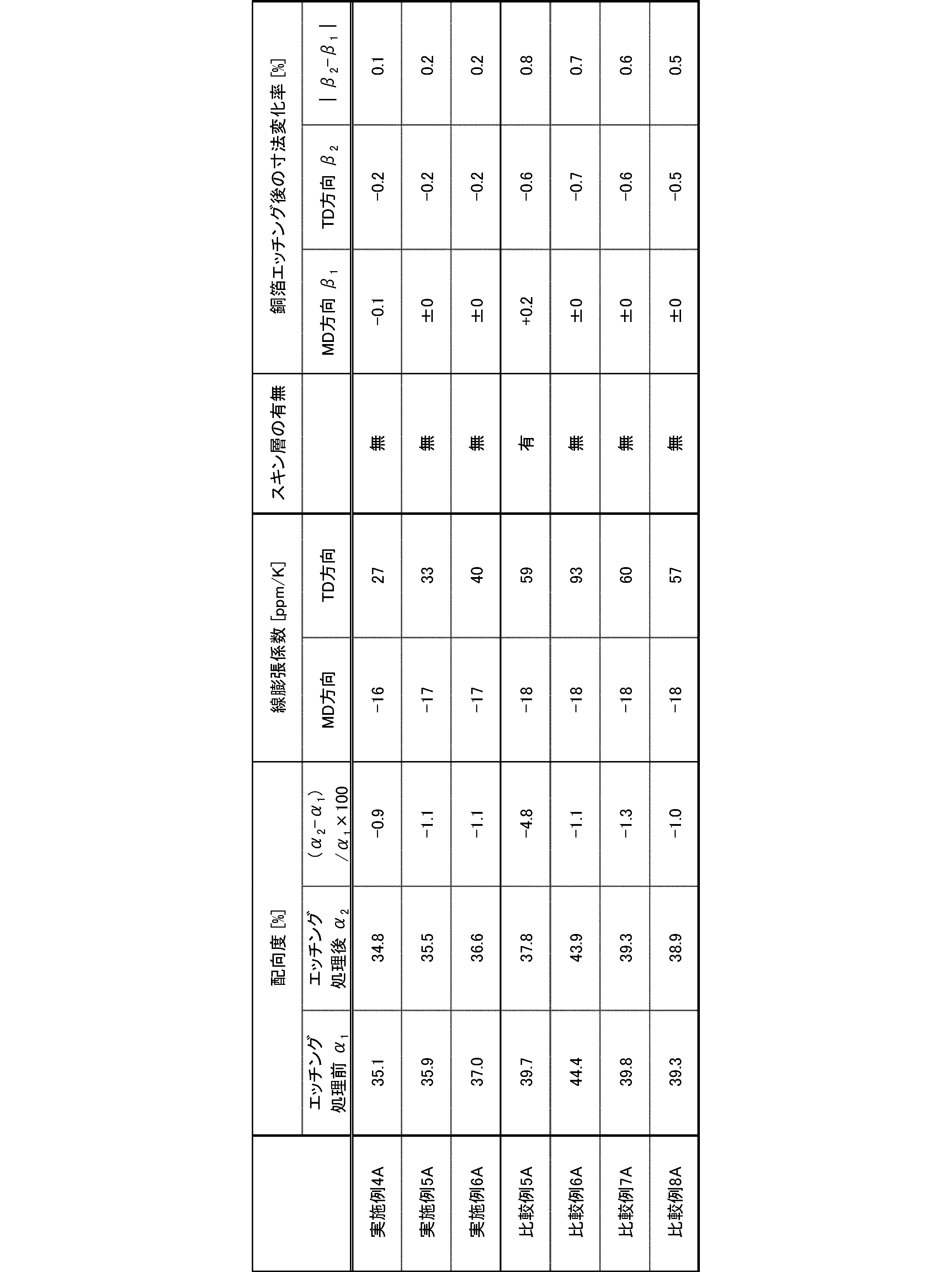

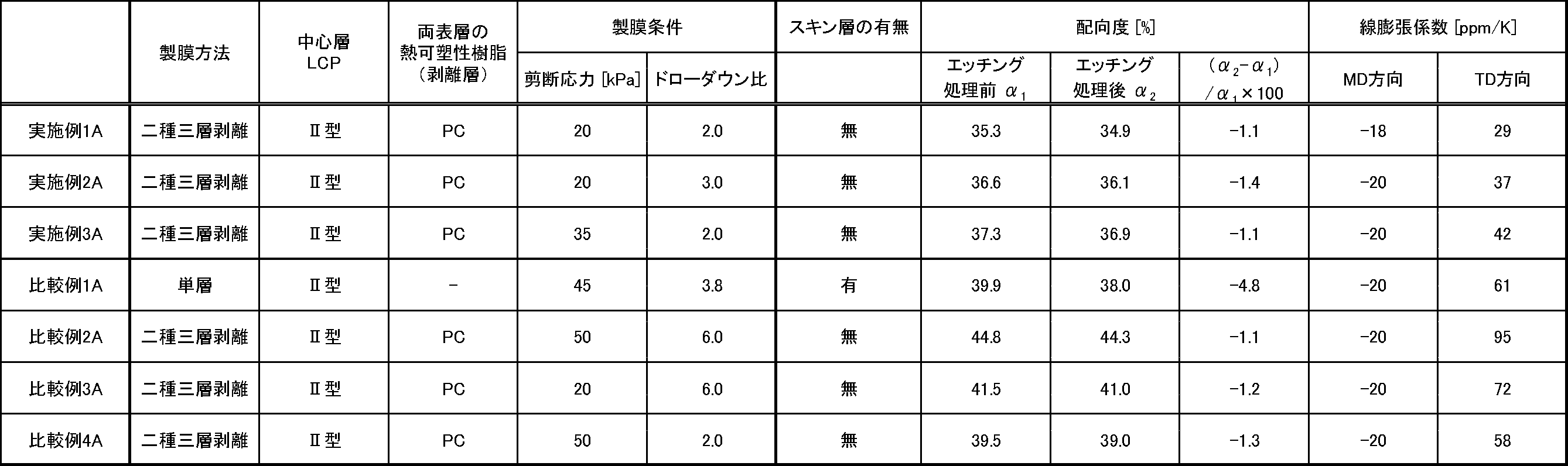


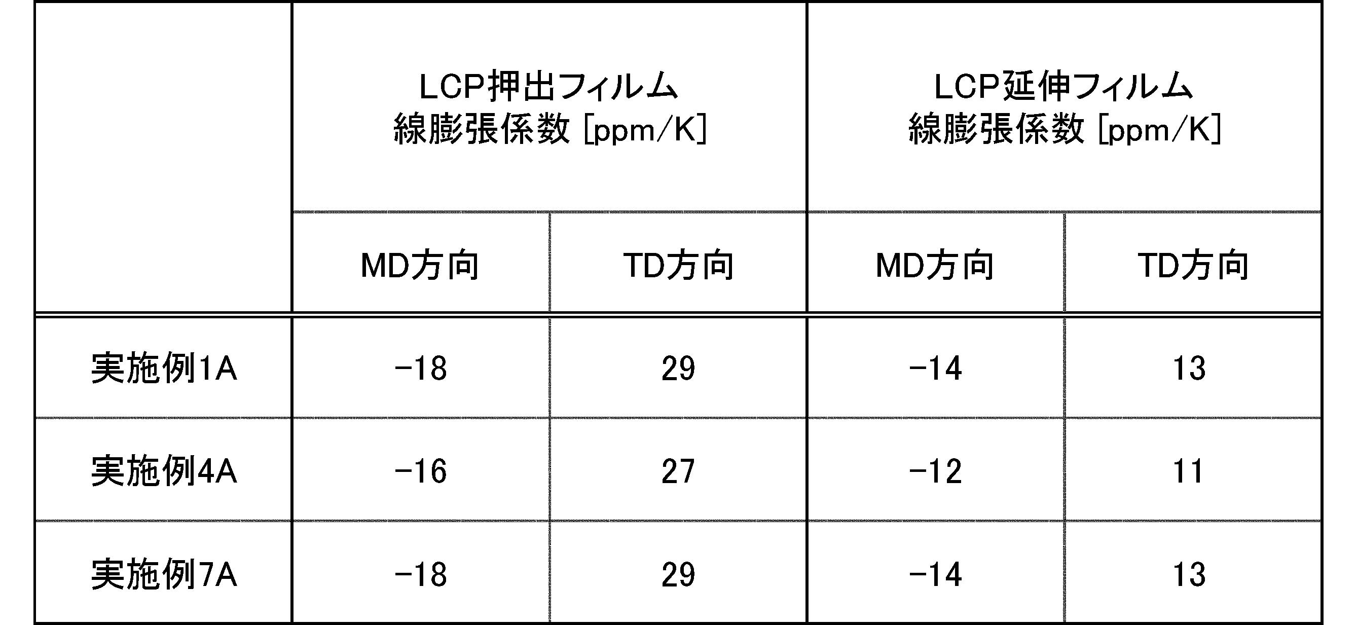
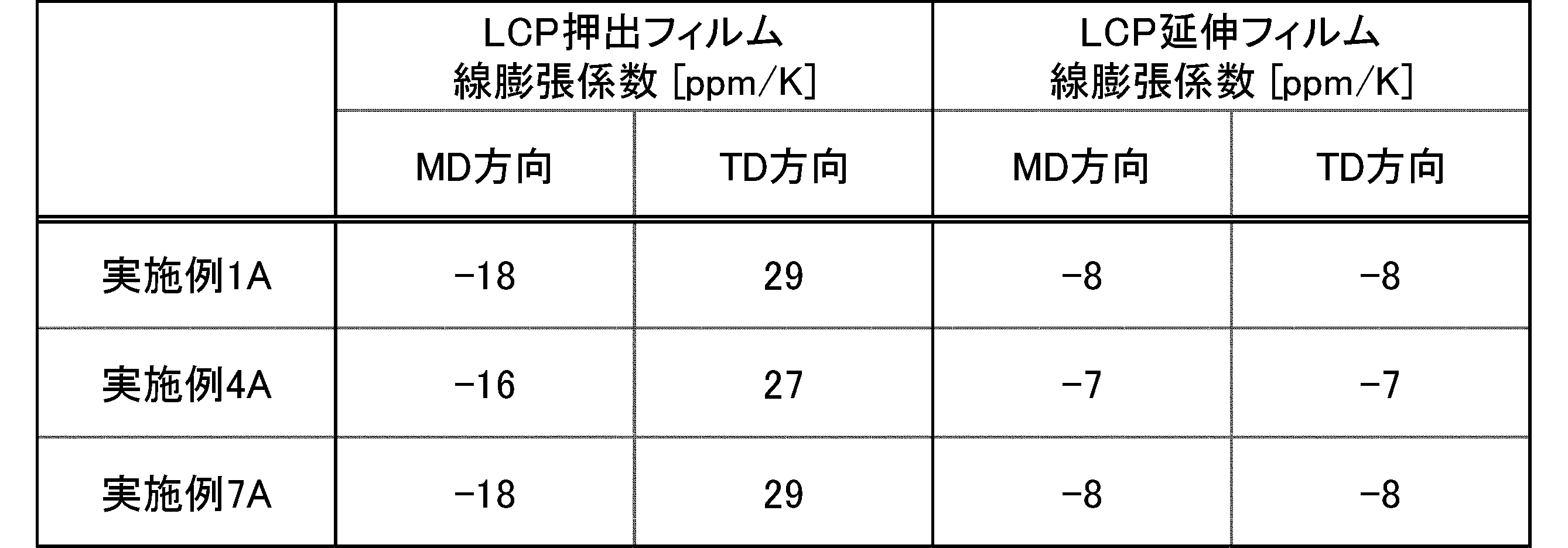
中間層としてII型熱可塑性液晶ポリマー(モノマー組成がp-ヒドロキシ安息香酸74mol%、6-ヒドロキシ-2-ナフトエ酸26mol%の共重合体、温度300℃及び剪断速度500sec-1の溶融粘度は80Pa・sec)を、中間層の両面の表層としてポリカーボネートPC(帝人社製パンライトL-1225L)をそれぞれ用いて、表12に示す成形条件で、ダイ幅600mm及びリップ開度0.2~1.0mmのTダイを備える二種三層押出機からTダイキャスティング法で各樹脂を300℃で共押出して、中間層が50μmの二種三層フィルムを成形した。成形した二種三層フィルムから両表層のポリカーボネートフィルムを巻取ラインでそれぞれ剥離し、融点280℃及び厚み50μmを有する実施例1B~3BのLCP押出フィルムをそれぞれ得た。
また、得られた一対の実施例1B~3Bの熱可塑性液晶ポリマーフィルム間にガラスクロス(IPC No.#1037)を挟み込んだ状態で、熱プレス機を用いて300℃で5分間の熱圧着処理を行うことで、融点280℃及び総厚み100μmを有する実施例1B~3Bの回路基板用絶縁材料を得た。
II型熱可塑性液晶ポリマー(モノマー組成がp-ヒドロキシ安息香酸74mol%、6-ヒドロキシ-2-ナフトエ酸26mol%の共重合体、温度300℃及び剪断速度500sec-1の溶融粘度は80Pa・sec)を用いて、表12に示す成形条件で、ダイ幅600mm及びリップ開度0.3mmのTダイを備える単層押出機からTダイキャスティング法で液晶ポリマーを300℃で押出して、融点280℃及び厚み50μmを有する比較例1BのLCP押出フィルムを得た。
成形条件を表12に記載のとおりに変更する以外は、実施例1Bと同様の方法で、融点280℃及び厚み50μmを有する比較例2B~4BのLCP押出フィルムをそれぞれ得た。

II型熱可塑性液晶ポリマーに代えてI型熱可塑性液晶ポリマー(モノマー組成がp-ヒドロキシ安息香酸79mol%、6-ヒドロキシ-2-ナフトエ酸20mol%、テレフタル酸1mol%の共重合体、温度330℃及び剪断速度500sec-1の溶融粘度は70Pa・sec)を中間層に用い、各樹脂を330℃で共押出した以外は、実施例1Bと同様の方法で、融点315℃及び厚み50μmを有する実施例4B~6BのLCP押出フィルムをそれぞれ得た。
また、得られた一対の実施例4B~6Bの熱可塑性液晶ポリマーフィルム間にガラスクロス(IPC No.#1037)を挟み込んだ状態で、熱プレス機を用いて330℃で5分間の熱圧着処理を行うことで、融点315℃及び総厚み100μmを有する実施例4B~6Bの回路基板用絶縁材料を得た。
II型熱可塑性液晶ポリマーに代えてI型熱可塑性液晶ポリマー(モノマー組成がp-ヒドロキシ安息香酸79mol%、6-ヒドロキシ-2-ナフトエ酸20mol%、テレフタル酸1mol%の共重合体、温度330℃及び剪断速度500sec-1の溶融粘度は70Pa・sec)を用い、液晶ポリマーを330℃で押出した以外は、比較例1Bと同様の方法で、融点315℃及び厚み50μmを有する比較例5BのLCP押出フィルムを得た。
成形条件を表13に記載のとおりに変更する以外は、実施例4Bと同様の方法で、融点315℃及び厚み50μmを有する比較例6B~8BのLCP押出フィルムをそれぞれ得た。
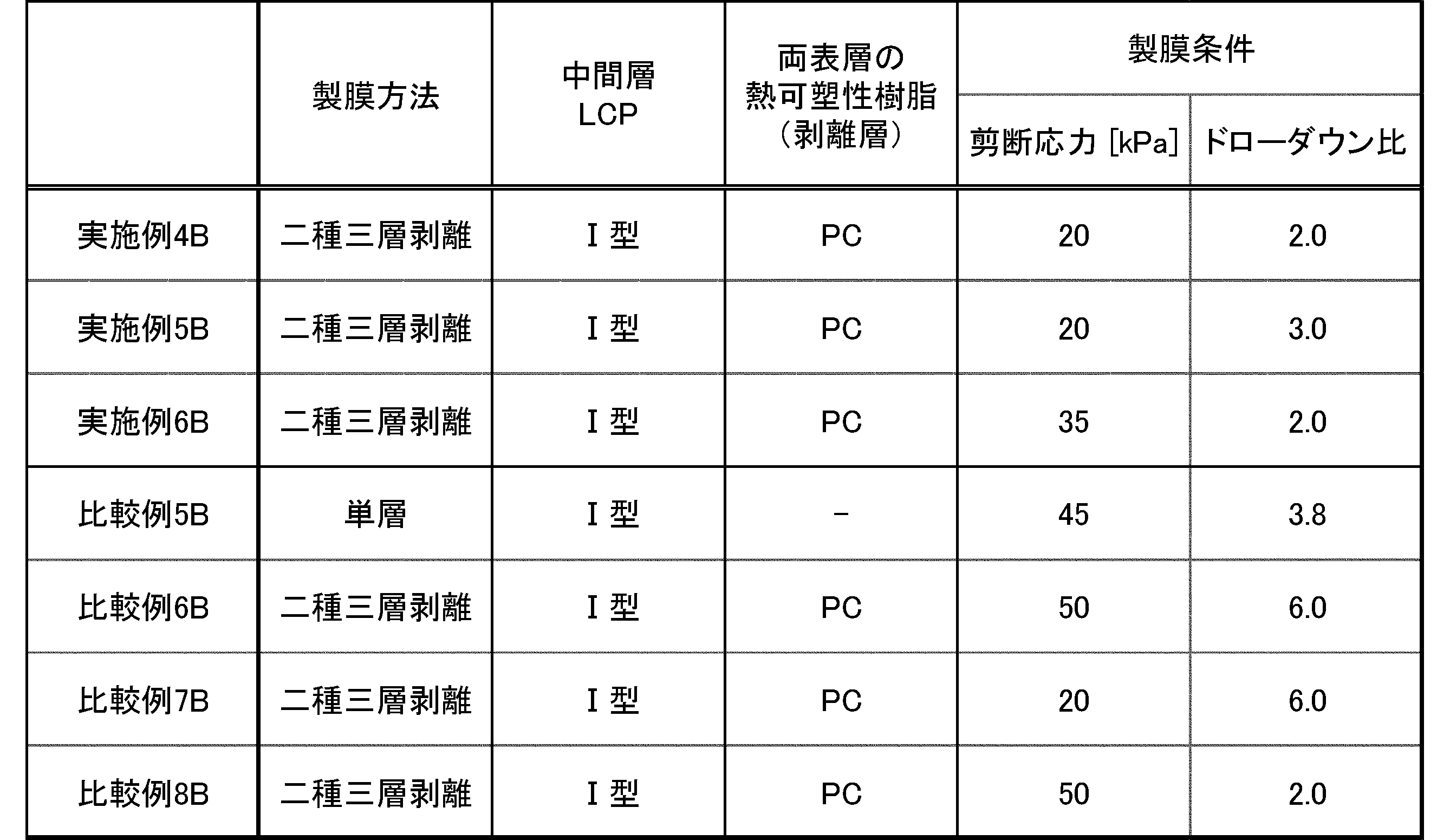
ポリカーボネートに代えて両面の表層にポリメチルペンテンPMP(三井化学社製TPX MX004)を用いる以外は、実施例1Bと同様の方法で、融点280℃及び厚み50μmを有する実施例7B~9BのLCP押出フィルムを得た。
また、得られた一対の実施例7B~9Bの熱可塑性液晶ポリマーフィルム間にガラスクロス(IPC No.#1037)を挟み込んだ状態で、熱プレス機を用いて300℃で5分間の熱圧着処理を行うことで、融点280℃及び総厚み100μmを有する実施例7B~9Bの回路基板用絶縁材料を得た。
成形条件を表14に記載のとおりに変更する以外は、実施例7Bと同様の方法で、融点280℃及び厚み50μmを有する比較例9B~11BのLCP押出フィルムをそれぞれ得た。

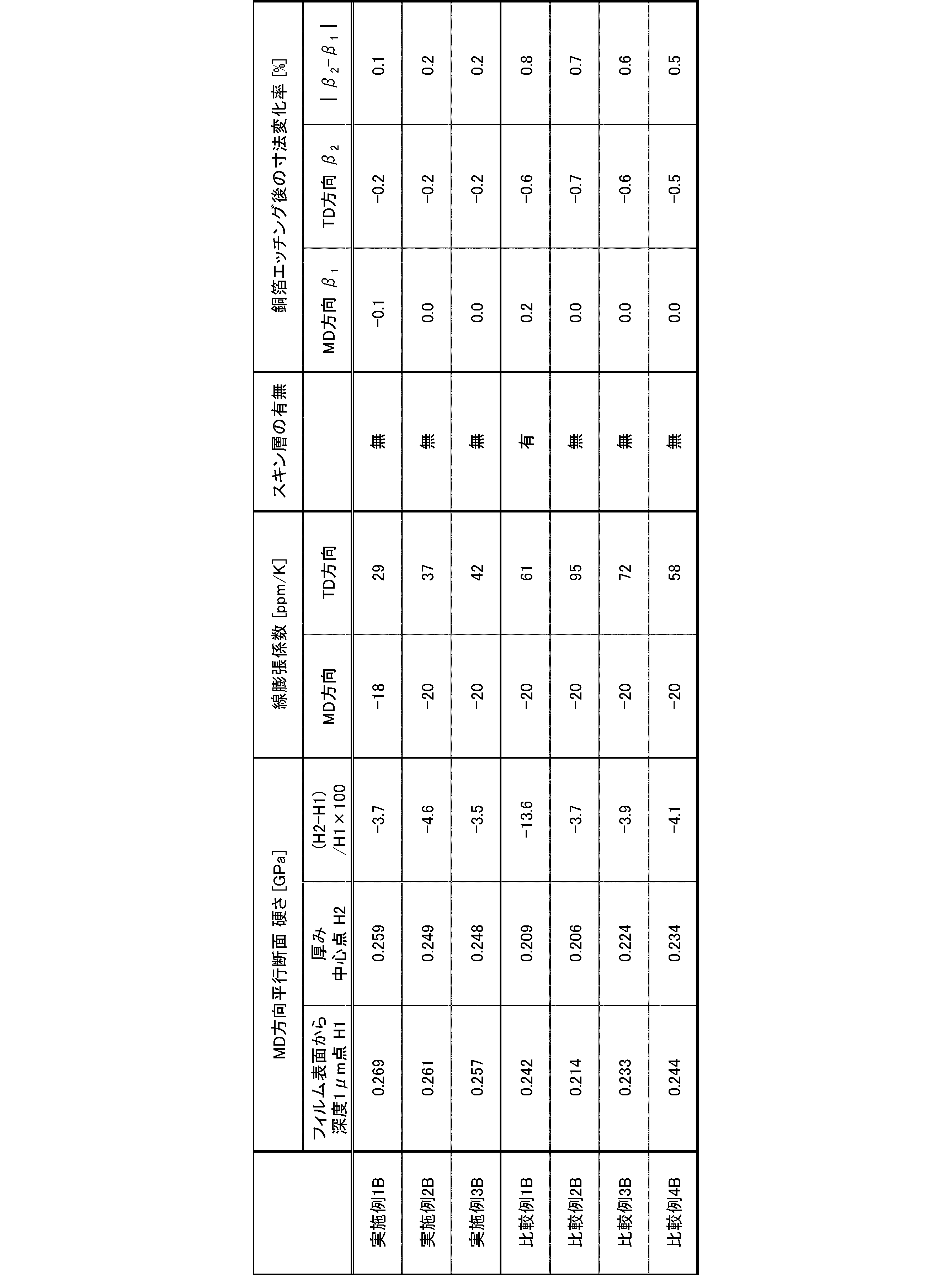

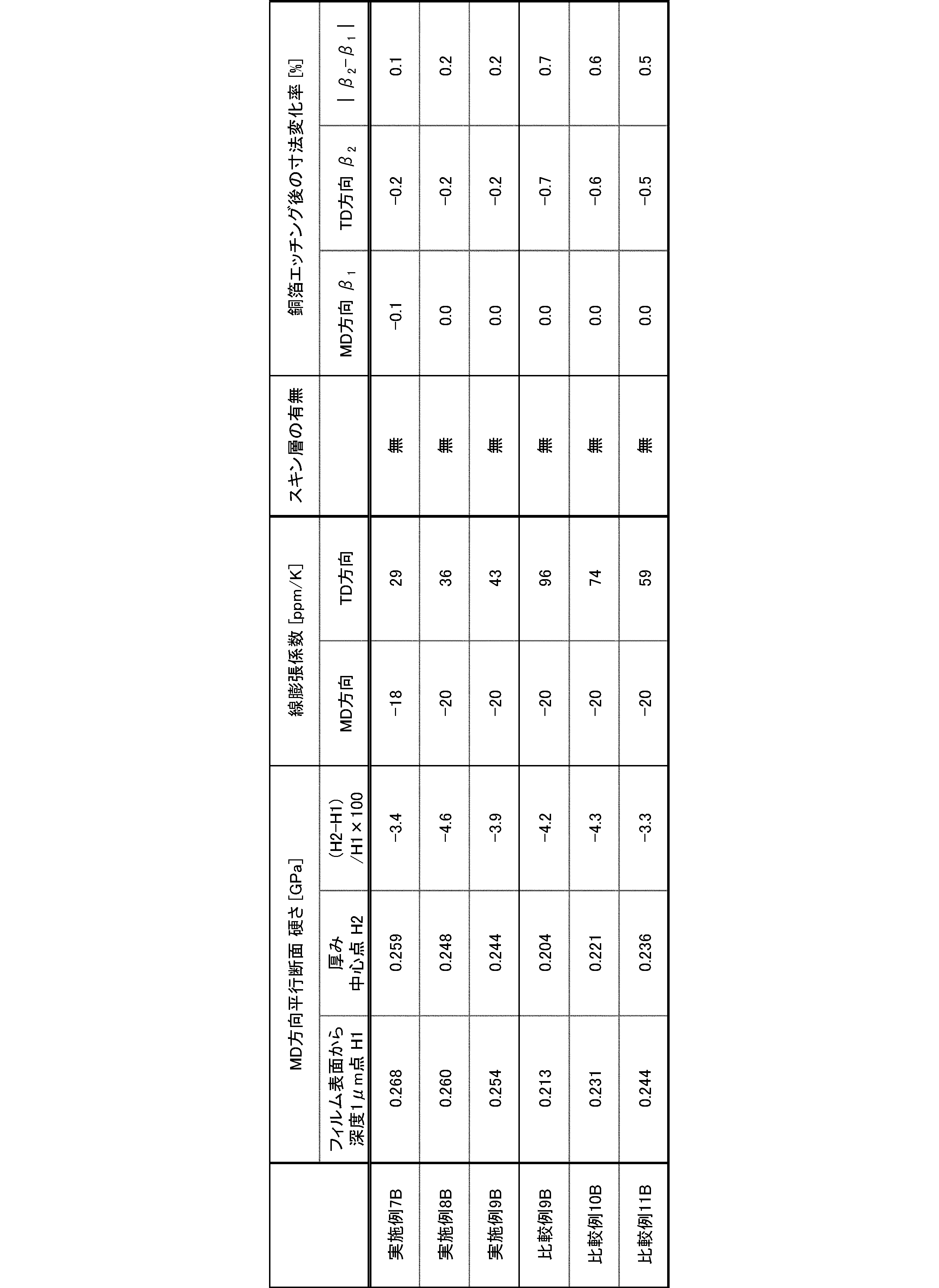

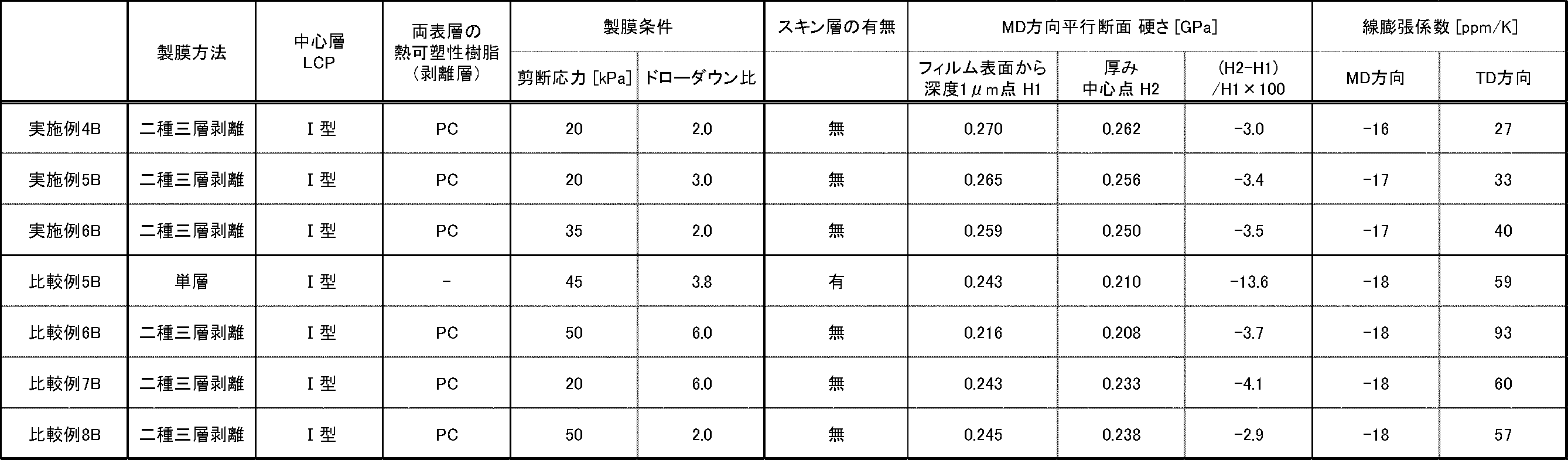


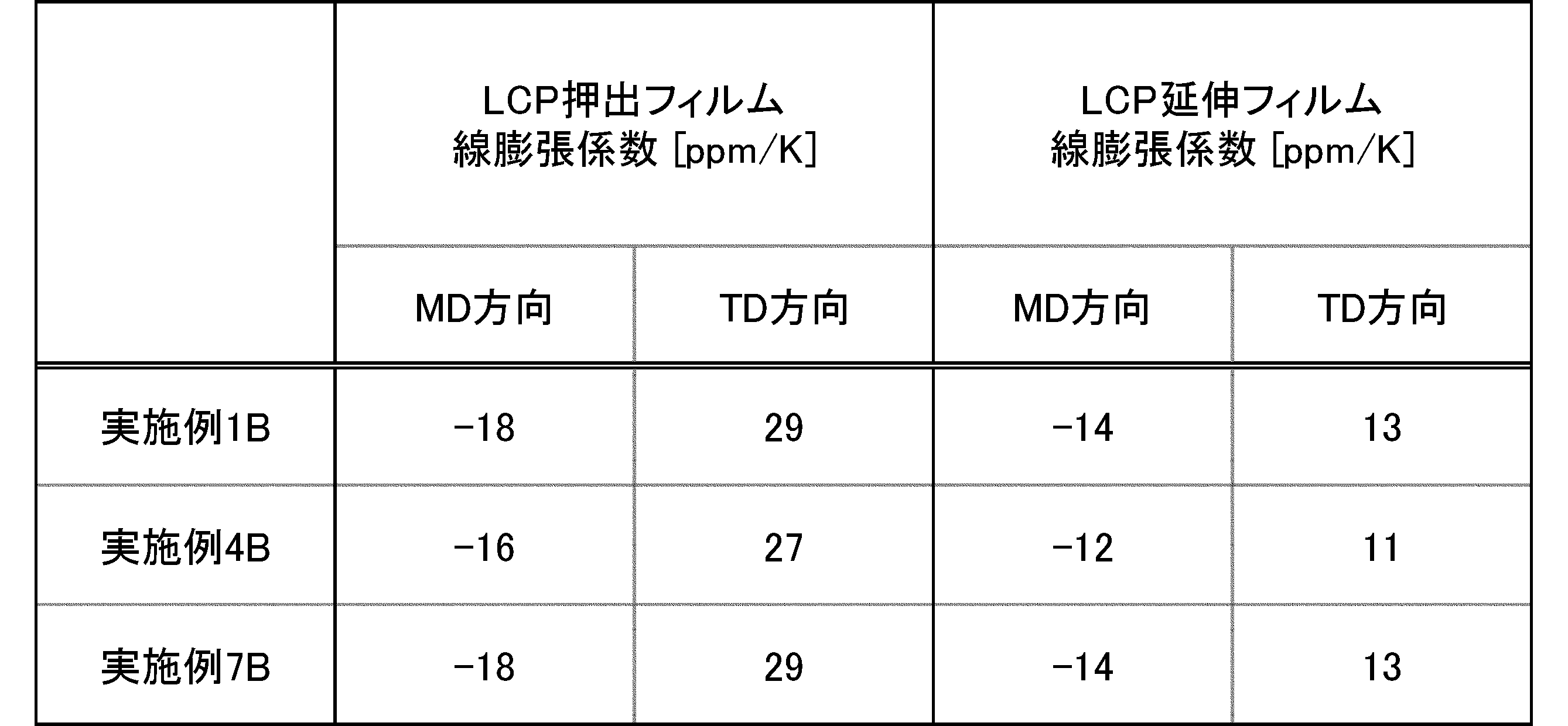
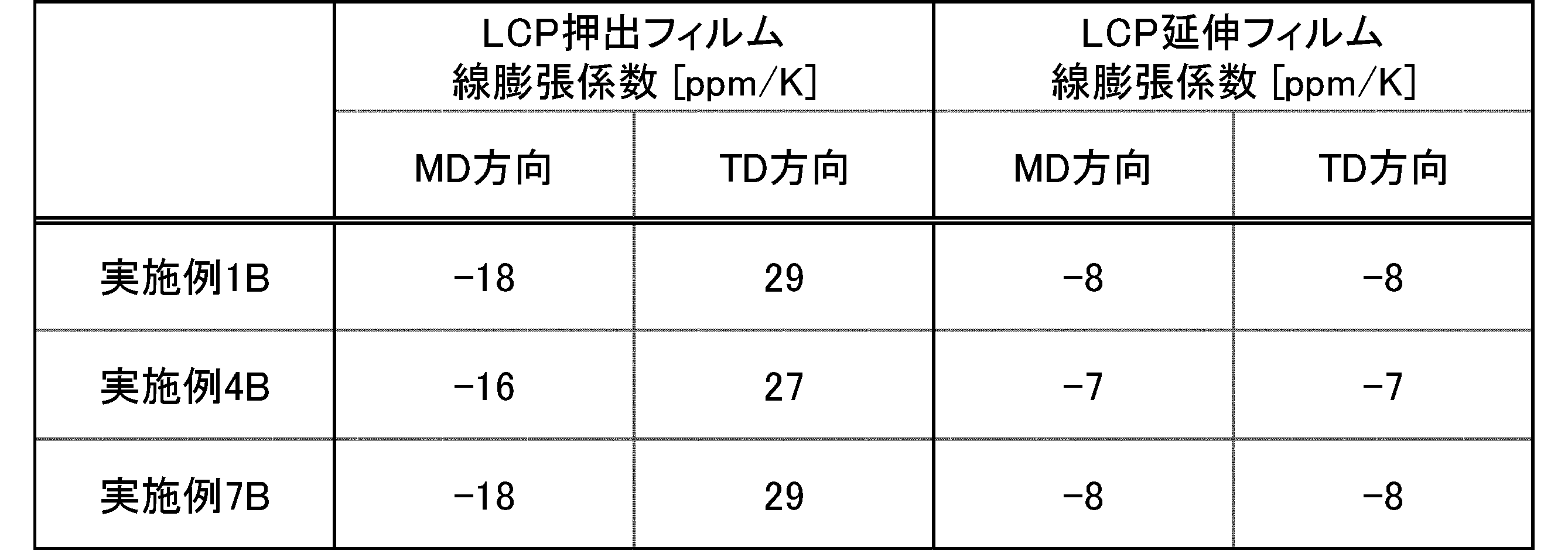
以下の条件で、各延伸処理用LCP押出フィルムの溶融粘度[Pa・sec]をそれぞれ測定した。
測定機器:キャピログラフ1D(東洋精機製作所社製)
使用装置:シリンダー長10.00mm、シリンダー径1.00mm、バレル径9.55mm
測定条件:延伸処理用LCP押出フィルムの押出成形時の温度[℃]と剪断速度[sec-1]
以下の条件で、各延伸処理用LCP押出フィルムの引張試験を行い、降伏点強度X及び破壊点強度Yを求めた。
JIS K7161-1:2014準拠
引張試験機:ストログラフVE1D(東洋精機製作所社製)
サンプルサイズ:ダンベル型
試験前の状態調整:23℃、50RH%で24時間
測定温度:200℃
引張速度:200mm/min
標線間距離:50mm
測定結果:5回測定の平均値
JIS K7197に準拠したTMA法で、各延伸処理用LCP押出フィルム及び各LCP延伸フィルムの線膨張係数をそれぞれ測定した。
測定機器: TMA 4000SE(NETZSCH社製)
測定方法: 引張モード
測定条件: サンプルサイズ 25mm×4mm×厚み50μm
チャック間距離 20mm
温度区間 23~200℃(2ndRUN)
昇温速度 5℃/min
雰囲気 窒素(流量50ml/min)
試験荷重 5gf
※熱履歴を解消した値をみるため、2ndRUNの値を採用
各延伸処理用LCP押出フィルムのフィルム表面について、JIS K5600-5-6に準拠したクロスカット法による密着性試験を行い、スキン層の有無をそれぞれ確認した。このとき、幅24mm×長さ50mmのニチバン社製セロテープ(登録商標)を使用し、テープを剥離した後に格子の目に剥がれがない場合を「スキン層なし」、剥がれがある場合を「スキン層あり」とした。
○ スキン層なし
× スキン層あり
中間層としてI型熱可塑性液晶ポリマー(モノマー組成がp-ヒドロキシ安息香酸79mol%、6-ヒドロキシ-2-ナフトエ酸20mol%、テレフタル酸1mol%の共重合体、温度330℃及び剪断速度500sec-1の溶融粘度は70Pa・sec)を、中間層の両面の表層としてポリカーボネートPC(帝人社製パンライトL-1225L)をそれぞれ用いて、剪断応力40kPa及びドローダウン比2.0の条件下で、ダイ幅600mm及びリップ開度0.2~1.0mmのTダイを備える二種三層押出機からTダイキャスティング法で各樹脂を330℃で共押出して、中間層が表24に記載の厚みを有する二種三層フィルムを成形した。成形した二種三層フィルムから両表層のポリカーボネートフィルムを巻取ラインでそれぞれ剥離し、融点315℃を有する実施例1C~3Cの延伸処理用LCP押出フィルムをそれぞれ得た。
剪断応力50kPa及びドローダウン比6.0の条件下で、ダイ幅600mm及びリップ開度0.2~1.0mmのTダイを備える単層押出機からTダイキャスティング法で液晶ポリマーを330℃で押出する以外は、実施例1Cと同様に行い、融点315℃を有する比較例1Cの延伸処理用LCP押出フィルムを得た。
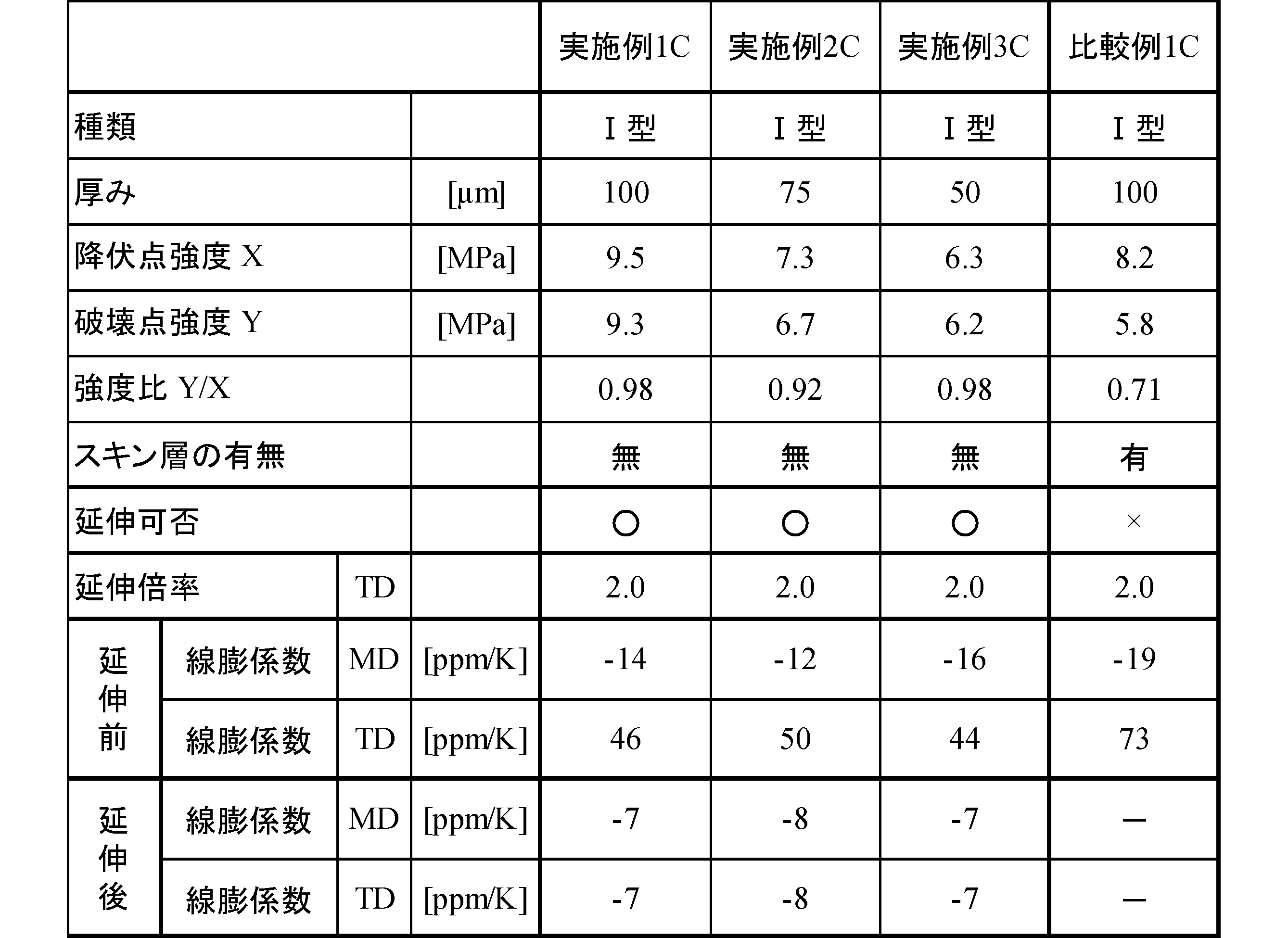
中間層としてII型熱可塑性液晶ポリマー(モノマー組成がp-ヒドロキシ安息香酸74mol%、6-ヒドロキシ-2-ナフトエ酸26mol%の共重合体、温度300℃及び剪断速度500sec-1の溶融粘度は80Pa・sec)を、中間層の両面の表層としてポリカーボネートPC(帝人社製パンライトL-1225L)をそれぞれ用いて、剪断応力40kPa及びドローダウン比2.0の条件下で、ダイ幅600mm及びリップ開度0.2~1.0mmのTダイを備える二種三層押出機からTダイキャスティング法で各樹脂を300℃で共押出して、中間層が表25に記載の厚みを有する二種三層フィルムを成形した。成形した二種三層フィルムから両表層のポリカーボネートフィルムを巻取ラインでそれぞれ剥離し、融点280℃を有する実施例4C~6Cの延伸処理用LCP押出フィルムをそれぞれ得た。
剪断応力60kPa及びドローダウン比6.0の条件下で、ダイ幅600mm及びリップ開度0.2~1.0mmのTダイを備える単層押出機からTダイキャスティング法で液晶ポリマーを300℃で押出する以外は、実施例4Cと同様に行い、融点280℃を有する比較例2Cの延伸処理用LCP押出フィルムを得た。
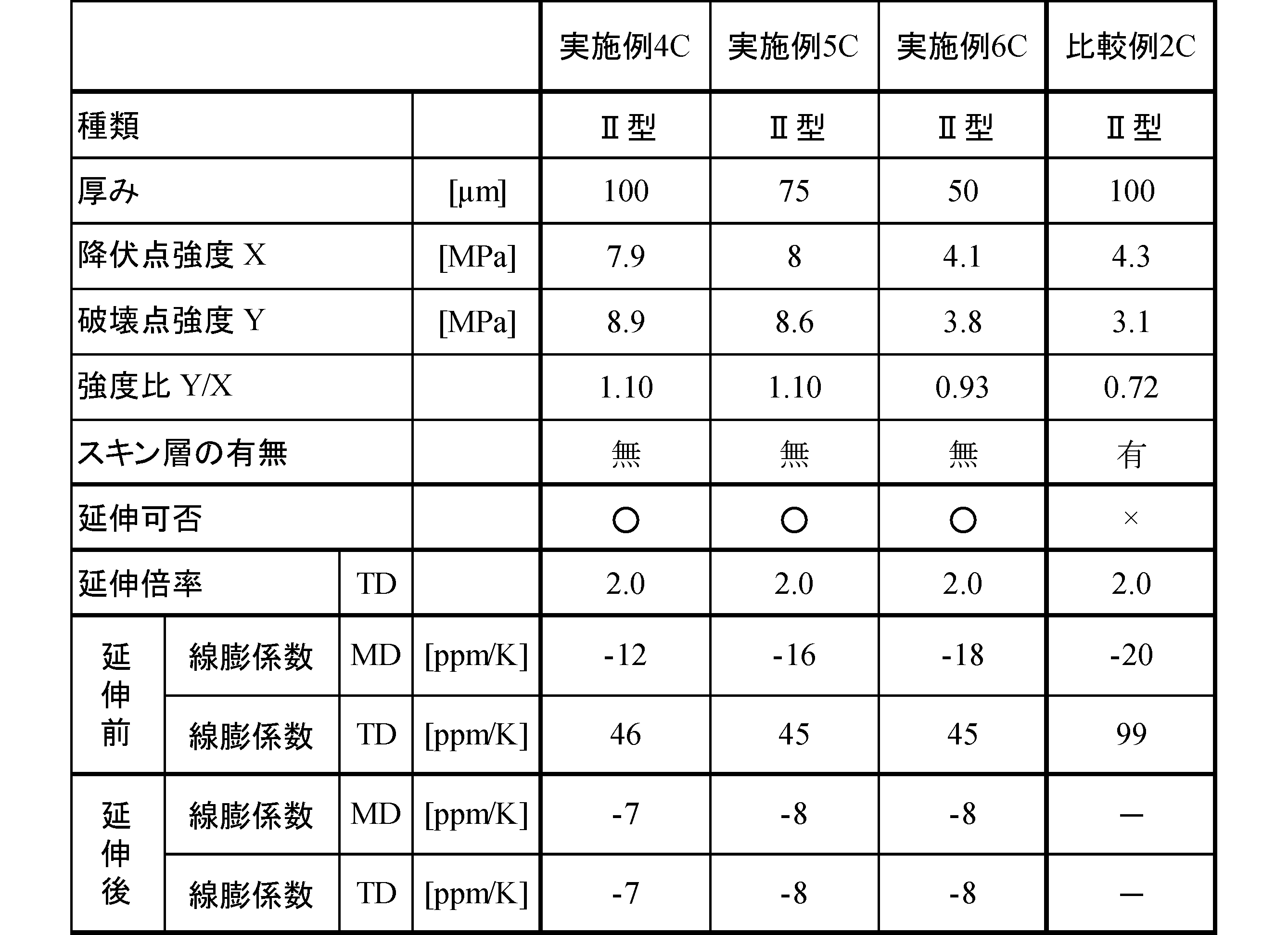
100a・・・面
100b・・・面
S1 ・・・フィルム表面
S2 ・・・深度5μmのフィルム表面
H1 ・・・深度1μm点の硬さ
H2 ・・・厚み中心点の硬さ
200 ・・・回路基板用絶縁材料
300 ・・・金属箔張積層板
400 ・・・金属箔張積層板
WF ・・・織布
MF ・・・金属箔
Y ・・・破壊点強度
100 ・・・LCP延伸フィルム
200 ・・・回路基板用絶縁材料
300 ・・・金属箔張積層板
400 ・・・金属箔張積層板
WF ・・・織布
MF ・・・金属箔
Claims (15)
- 熱可塑性液晶ポリマーを含み15μm以上300μm以下の厚みを有するLCP押出フィルムであって、
下記条件(A)及び/又は(B)を満たす、LCP押出フィルム。
(A)露出しているフィルム表面S1を含む配向度α1(%)と、前記フィルム表面S1を厚み方向にエッチング処理することで露出する、前記フィルム表面S1から深度5μmに位置するフィルム表面S2を含む配向度α2(%)とが、-4.0≦[(α2-α1)/α1]×100≦0.0の関係を満たし、且つ、JIS K7197に準拠したTMA法によって測定される23~200℃におけるMD方向及びTD方向の線膨張係数が-30~55ppm/Kの範囲内にある。
(B)MD方向に平行なフィルム断面に対してナノインデンテーション法で測定した、フィルム表面から厚み方向に1μmに位置する深度1μm点の硬さH1と厚み中心点の硬さH2とが、-10.0≦100×(H2-H1)/H1≦0.0を満たし、且つ、JIS K7197に準拠したTMA法によって測定される23~200℃におけるMD方向及びTD方向の線膨張係数が-30~55ppm/Kの範囲内にある。 - 前記TD方向の前記線膨張係数が、0~55ppm/Kである
請求項1に記載のLCP押出フィルム。 - 外層、中間層、及び外層を有する積層押出フィルムから前記両外層を除いた、前記中間層である
請求項1又は2に記載のLCP押出フィルム。 - 前記フィルム表面S1に、JIS K5600-5-6に準拠したクロスカット法による密着性試験で、テープ剥離可能なスキン層を有さない
請求項1~3のいずれか一項に記載のLCP押出フィルム。 - 前記条件(A)において、前記表面S2を含む前記配向度α2が、37.7(%)以下である
請求項1~4のいずれか一項に記載のLCP押出フィルム。 - 前記条件(A)において、前記フィルム表面S1を含む前記配向度α1が、39.0(%)以下である
請求項1~5のいずれか一項に記載のLCP押出フィルム。 - 前記条件(B)において、前記厚み中心点の前記硬さH2が、0.240(GPa)以上である
請求項1~6のいずれか一項に記載のLCP押出フィルム。 - 前記条件(B)において、前記深度1μm点の前記硬さH1が、0.250(GPa)以上である
請求項1~7のいずれか一項に記載のLCP押出フィルム。 - 無機フィラーをさらに含有する
請求項1~8のいずれか一項に記載のLCP押出フィルム。 - Tダイ押出フィルムである
請求項1~9のいずれか一項に記載のLCP押出フィルム。 - 請求項1~10のいずれか一項に記載のLCP押出フィルム及び前記LCP押出フィルムの少なくとも一方の面に設けられた織布を少なくとも有する積層体を備える、
回路基板用絶縁材料。 - 請求項1~10のいずれか一項に記載のLCP押出フィルム及び前記LCP押出フィルムの片面及び/又は両面に設けられた金属箔を備える、
金属箔張積層板。 - 請求項1~10のいずれか一項に記載のLCP押出フィルム及び織布を少なくとも有する積層体と、前記積層体の片面及び/又は両面に設けられた金属箔とを備える、
金属箔張積層板。 - 請求項1~10のいずれか一項に記載のLCP押出フィルムの延伸体を備える、
LCP延伸フィルム。 - 前記延伸体は、前記LCP押出フィルムに対して1.3~2.5倍の延伸倍率(MD方向×TD方向)を有する
請求項14に記載のLCP延伸フィルム。
Priority Applications (9)
| Application Number | Priority Date | Filing Date | Title |
|---|---|---|---|
| KR1020237022786A KR20230119162A (ko) | 2020-12-09 | 2021-12-07 | Lcp 압출 필름 및 그의 제조 방법, 연신 처리용 lcp압출 필름, lcp 연신 필름, 열수축성 lcp 연신 필름, 회로 기판용 절연 재료, 그리고 금속박을 붙인 적층판 |
| CN202311289930.9A CN117301463A (zh) | 2020-12-09 | 2021-12-07 | Lcp挤出膜及其制造方法、拉伸处理用lcp挤出膜、lcp拉伸膜、热收缩性lcp拉伸膜、电路基板用绝缘材料及覆金属箔层叠板 |
| KR1020237043724A KR20240001268A (ko) | 2020-12-09 | 2021-12-07 | Lcp 압출 필름 및 그의 제조 방법, 연신 처리용 lcp 압출 필름, lcp 연신 필름, 열수축성 lcp 연신 필름, 회로 기판용 절연 재료, 그리고 금속박을 붙인 적층판 |
| CN202311289318.1A CN117400571A (zh) | 2020-12-09 | 2021-12-07 | Lcp挤出膜及其制造方法、拉伸处理用lcp挤出膜、lcp拉伸膜、热收缩性lcp拉伸膜、电路基板用绝缘材料及覆金属箔层叠板 |
| CN202180082926.8A CN116710278A (zh) | 2020-12-09 | 2021-12-07 | Lcp挤出膜及其制造方法、拉伸处理用lcp挤出膜、lcp拉伸膜、热收缩性lcp拉伸膜、电路基板用绝缘材料及覆金属箔层叠板 |
| US18/266,228 US12447661B2 (en) | 2020-12-09 | 2021-12-07 | LCP extruded film and method for manufacturing the same, LCP extruded film for stretch treatment, LCP stretched film, heat-shrinkable LCP stretched film, insulating material for circuit substrate, and metal foil-clad laminate |
| KR1020237043725A KR20240001269A (ko) | 2020-12-09 | 2021-12-07 | Lcp 압출 필름 및 그의 제조 방법, 연신 처리용 lcp 압출 필름, lcp 연신 필름, 열수축성 lcp 연신 필름, 회로 기판용 절연 재료, 그리고 금속박을 붙인 적층판 |
| US18/375,798 US12447662B2 (en) | 2020-12-09 | 2023-10-02 | LCP extruded film and method for manufacturing the same, LCP extruded film for stretch treatment, LCP stretched film, heat-shrinkable LCP stretched film, insulating material for circuit substrate, and metal foil-clad laminate |
| US18/375,800 US12454088B2 (en) | 2020-12-09 | 2023-10-02 | LCP extruded film and method for manufacturing the same, LCP extruded film for stretch treatment, LCP stretched film, heat-shrinkable LCP stretched film, insulating material for circuit substrate, and metal foil-clad laminate |
Applications Claiming Priority (14)
| Application Number | Priority Date | Filing Date | Title |
|---|---|---|---|
| JP2020204317A JP7630264B2 (ja) | 2020-12-09 | 2020-12-09 | Lcp押出フィルムの製造方法 |
| JP2020204271 | 2020-12-09 | ||
| JP2020204359A JP7638689B2 (ja) | 2020-12-09 | 2020-12-09 | Lcp押出フィルムの製造方法 |
| JP2020-204359 | 2020-12-09 | ||
| JP2020-204305 | 2020-12-09 | ||
| JP2020-204271 | 2020-12-09 | ||
| JP2020204305 | 2020-12-09 | ||
| JP2020-204317 | 2020-12-09 | ||
| JP2021-182543 | 2021-11-09 | ||
| JP2021-182583 | 2021-11-09 | ||
| JP2021182534A JP2023070392A (ja) | 2021-11-09 | 2021-11-09 | 延伸処理用lcp押出フィルム、熱収縮性lcp延伸フィルム、回路基板用絶縁材料、及び金属箔張積層板 |
| JP2021-182534 | 2021-11-09 | ||
| JP2021182583A JP2022091688A (ja) | 2020-12-09 | 2021-11-09 | Lcp押出フィルム、lcp延伸フィルム、回路基板用絶縁材料、及び金属箔張積層板 |
| JP2021182543A JP2022091687A (ja) | 2020-12-09 | 2021-11-09 | Lcp押出フィルム、lcp延伸フィルム、回路基板用絶縁材料、及び金属箔張積層板 |
Related Child Applications (3)
| Application Number | Title | Priority Date | Filing Date |
|---|---|---|---|
| US18/266,228 A-371-Of-International US12447661B2 (en) | 2020-12-09 | 2021-12-07 | LCP extruded film and method for manufacturing the same, LCP extruded film for stretch treatment, LCP stretched film, heat-shrinkable LCP stretched film, insulating material for circuit substrate, and metal foil-clad laminate |
| US18/375,798 Division US12447662B2 (en) | 2020-12-09 | 2023-10-02 | LCP extruded film and method for manufacturing the same, LCP extruded film for stretch treatment, LCP stretched film, heat-shrinkable LCP stretched film, insulating material for circuit substrate, and metal foil-clad laminate |
| US18/375,800 Division US12454088B2 (en) | 2020-12-09 | 2023-10-02 | LCP extruded film and method for manufacturing the same, LCP extruded film for stretch treatment, LCP stretched film, heat-shrinkable LCP stretched film, insulating material for circuit substrate, and metal foil-clad laminate |
Publications (1)
| Publication Number | Publication Date |
|---|---|
| WO2022124308A1 true WO2022124308A1 (ja) | 2022-06-16 |
Family
ID=81974537
Family Applications (1)
| Application Number | Title | Priority Date | Filing Date |
|---|---|---|---|
| PCT/JP2021/044969 Ceased WO2022124308A1 (ja) | 2020-12-09 | 2021-12-07 | Lcp押出フィルム及びその製造方法、延伸処理用lcp押出フィルム、lcp延伸フィルム、熱収縮性lcp延伸フィルム、回路基板用絶縁材料、並びに金属箔張積層板 |
Country Status (4)
| Country | Link |
|---|---|
| US (3) | US12447661B2 (ja) |
| KR (3) | KR20230119162A (ja) |
| TW (3) | TW202404809A (ja) |
| WO (1) | WO2022124308A1 (ja) |
Cited By (7)
| Publication number | Priority date | Publication date | Assignee | Title |
|---|---|---|---|---|
| WO2023140187A1 (ja) * | 2022-01-21 | 2023-07-27 | デンカ株式会社 | 液晶ポリマーフィルム、並びに、これを用いた回路基板用絶縁材料及び金属箔張積層板 |
| JPWO2024166775A1 (ja) * | 2023-02-09 | 2024-08-15 | ||
| JPWO2024166774A1 (ja) * | 2023-02-09 | 2024-08-15 | ||
| JPWO2024166776A1 (ja) * | 2023-02-09 | 2024-08-15 | ||
| JP7589907B1 (ja) | 2023-09-04 | 2024-11-26 | 合同会社ニスティ | 金属張積層体の製造方法 |
| JPWO2025127113A1 (ja) * | 2023-12-12 | 2025-06-19 | ||
| KR20250148562A (ko) | 2023-02-03 | 2025-10-14 | 도요 고한 가부시키가이샤 | 액정 폴리머 필름 연신용 3층 필름, 연신 3층 필름 및 연신 액정 폴리머 필름, 그리고 이들의 제조 방법 |
Citations (8)
| Publication number | Priority date | Publication date | Assignee | Title |
|---|---|---|---|---|
| JPH0890570A (ja) * | 1994-09-16 | 1996-04-09 | Hoechst Celanese Corp | 液晶ポリマーフイルムの処理方法 |
| JPH1034742A (ja) * | 1996-07-19 | 1998-02-10 | Japan Gore Tex Inc | 液晶ポリマーフィルム及びその積層体 |
| JP2001506767A (ja) * | 1996-12-05 | 2001-05-22 | ヘキスト・セラニーズ・コーポレーション | 剥離性の熱可塑性スキン層 |
| JP2014116593A (ja) * | 2012-11-13 | 2014-06-26 | Mitsubishi Gas Chemical Co Inc | 金属張積層板及びその製造方法、並びにそれを用いたプリント配線板及びその製造方法 |
| JP2017101200A (ja) * | 2015-12-04 | 2017-06-08 | 株式会社プライマテック | 長尺液晶ポリマーフィルム |
| WO2020013106A1 (ja) * | 2018-07-10 | 2020-01-16 | デンカ株式会社 | 熱可塑性液晶ポリマーフィルム、その製造方法およびフレキシブル銅張積層板 |
| WO2020166644A1 (ja) * | 2019-02-15 | 2020-08-20 | 住友化学株式会社 | フィルム及び積層体 |
| WO2021251265A1 (ja) * | 2020-06-09 | 2021-12-16 | 株式会社クラレ | 熱可塑性液晶ポリマー成形体 |
Family Cites Families (10)
| Publication number | Priority date | Publication date | Assignee | Title |
|---|---|---|---|---|
| JP2539382B2 (ja) | 1986-07-28 | 1996-10-02 | 住友ベークライト株式会社 | 液晶フイルムの製造方法 |
| JPH02178016A (ja) | 1988-12-28 | 1990-07-11 | Daicel Chem Ind Ltd | 液晶性ポリマーフイルム及びその製造方法 |
| JP3804528B2 (ja) | 2001-12-18 | 2006-08-02 | 住友化学株式会社 | 多層発泡シートの製造方法 |
| JP2008052170A (ja) | 2006-08-28 | 2008-03-06 | Konica Minolta Holdings Inc | 偏光フィルム、偏光フィルムの製造方法、及びそれを用いた偏光板、液晶ディスプレイ |
| US7973239B2 (en) | 2007-03-20 | 2011-07-05 | Sumitomo Electric Industries, Ltd. | Ultrafine-coaxial-wire harness, connecting method thereof, circuit-board-connected body, circuit-board module, and electronic apparatus |
| KR101545032B1 (ko) | 2007-08-24 | 2015-08-17 | 이스트만 케미칼 컴파니 | 저복굴절을 갖는 혼합 셀룰로스 에스터 및 이로부터 제조된 필름 |
| KR101741378B1 (ko) | 2008-11-07 | 2017-05-29 | 테이진 카세이 가부시키가이샤 | 위상차 필름 |
| WO2013091073A1 (en) | 2011-12-19 | 2013-06-27 | National Research Counsil Of Canada | Co-extruded ultra thin films |
| US20140265010A1 (en) * | 2013-03-13 | 2014-09-18 | Transitions Optical, Inc. | Method of preparing photochromic-dichroic films having reduced optical distortion |
| US11322442B2 (en) | 2018-01-05 | 2022-05-03 | Semiconductor Energy Laboratory Co., Ltd. | Semiconductor device including transistor with oxide semiconductor and method for manufacturing the semiconductor device |
-
2021
- 2021-12-07 KR KR1020237022786A patent/KR20230119162A/ko active Pending
- 2021-12-07 WO PCT/JP2021/044969 patent/WO2022124308A1/ja not_active Ceased
- 2021-12-07 KR KR1020237043724A patent/KR20240001268A/ko active Pending
- 2021-12-07 US US18/266,228 patent/US12447661B2/en active Active
- 2021-12-07 KR KR1020237043725A patent/KR20240001269A/ko active Pending
- 2021-12-09 TW TW112137249A patent/TW202404809A/zh unknown
- 2021-12-09 TW TW112137248A patent/TW202402503A/zh unknown
- 2021-12-09 TW TW110146092A patent/TWI896822B/zh active
-
2023
- 2023-10-02 US US18/375,798 patent/US12447662B2/en active Active
- 2023-10-02 US US18/375,800 patent/US12454088B2/en active Active
Patent Citations (8)
| Publication number | Priority date | Publication date | Assignee | Title |
|---|---|---|---|---|
| JPH0890570A (ja) * | 1994-09-16 | 1996-04-09 | Hoechst Celanese Corp | 液晶ポリマーフイルムの処理方法 |
| JPH1034742A (ja) * | 1996-07-19 | 1998-02-10 | Japan Gore Tex Inc | 液晶ポリマーフィルム及びその積層体 |
| JP2001506767A (ja) * | 1996-12-05 | 2001-05-22 | ヘキスト・セラニーズ・コーポレーション | 剥離性の熱可塑性スキン層 |
| JP2014116593A (ja) * | 2012-11-13 | 2014-06-26 | Mitsubishi Gas Chemical Co Inc | 金属張積層板及びその製造方法、並びにそれを用いたプリント配線板及びその製造方法 |
| JP2017101200A (ja) * | 2015-12-04 | 2017-06-08 | 株式会社プライマテック | 長尺液晶ポリマーフィルム |
| WO2020013106A1 (ja) * | 2018-07-10 | 2020-01-16 | デンカ株式会社 | 熱可塑性液晶ポリマーフィルム、その製造方法およびフレキシブル銅張積層板 |
| WO2020166644A1 (ja) * | 2019-02-15 | 2020-08-20 | 住友化学株式会社 | フィルム及び積層体 |
| WO2021251265A1 (ja) * | 2020-06-09 | 2021-12-16 | 株式会社クラレ | 熱可塑性液晶ポリマー成形体 |
Cited By (11)
| Publication number | Priority date | Publication date | Assignee | Title |
|---|---|---|---|---|
| WO2023140187A1 (ja) * | 2022-01-21 | 2023-07-27 | デンカ株式会社 | 液晶ポリマーフィルム、並びに、これを用いた回路基板用絶縁材料及び金属箔張積層板 |
| KR20250148562A (ko) | 2023-02-03 | 2025-10-14 | 도요 고한 가부시키가이샤 | 액정 폴리머 필름 연신용 3층 필름, 연신 3층 필름 및 연신 액정 폴리머 필름, 그리고 이들의 제조 방법 |
| JPWO2024166775A1 (ja) * | 2023-02-09 | 2024-08-15 | ||
| JPWO2024166774A1 (ja) * | 2023-02-09 | 2024-08-15 | ||
| JPWO2024166776A1 (ja) * | 2023-02-09 | 2024-08-15 | ||
| WO2024166774A1 (ja) * | 2023-02-09 | 2024-08-15 | デンカ株式会社 | Lcpフィルムの製造方法 |
| WO2024166775A1 (ja) * | 2023-02-09 | 2024-08-15 | デンカ株式会社 | Lcpフィルム |
| JP7589907B1 (ja) | 2023-09-04 | 2024-11-26 | 合同会社ニスティ | 金属張積層体の製造方法 |
| JP2025036137A (ja) * | 2023-09-04 | 2025-03-14 | 合同会社ニスティ | 金属張積層体の製造方法 |
| JPWO2025127113A1 (ja) * | 2023-12-12 | 2025-06-19 | ||
| WO2025127113A1 (ja) * | 2023-12-12 | 2025-06-19 | 東洋鋼鈑株式会社 | 液晶ポリマーフィルム積層体、液晶ポリマーフィルム積層体の製造方法、および液晶ポリマーフィルムの製造方法 |
Also Published As
| Publication number | Publication date |
|---|---|
| TW202235286A (zh) | 2022-09-16 |
| KR20240001269A (ko) | 2024-01-03 |
| TWI896822B (zh) | 2025-09-11 |
| TW202402503A (zh) | 2024-01-16 |
| US20240025102A1 (en) | 2024-01-25 |
| TW202404809A (zh) | 2024-02-01 |
| US20240032191A1 (en) | 2024-01-25 |
| US12454088B2 (en) | 2025-10-28 |
| KR20230119162A (ko) | 2023-08-16 |
| US12447661B2 (en) | 2025-10-21 |
| US12447662B2 (en) | 2025-10-21 |
| US20240043635A1 (en) | 2024-02-08 |
| KR20240001268A (ko) | 2024-01-03 |
Similar Documents
| Publication | Publication Date | Title |
|---|---|---|
| TWI896822B (zh) | Lcp押出膜及其製造方法、延伸處理用lcp押出膜、lcp延伸膜、熱收縮性lcp延伸膜、電路基板用絕緣材料、與金屬箔貼合積層板 | |
| JP6930046B1 (ja) | 回路基板用lcpフィルムの製造方法、及び回路基板用tダイ溶融押出lcpフィルム | |
| JP7753238B2 (ja) | 回路基板用絶縁材料及びその製造方法、並びに金属箔張積層板 | |
| JP2026067878A (ja) | Lcp押出フィルム、lcp延伸フィルム、回路基板用絶縁材料、及び金属箔張積層板 | |
| JP7546064B2 (ja) | 回路基板用絶縁材料、及び金属箔張積層板 | |
| JP2023106957A (ja) | 熱圧着積層フィルムの巻回ロール | |
| TWI861550B (zh) | Lcp押出膜、電路基板用絕緣材料、及金屬箔積層板 | |
| JP7630264B2 (ja) | Lcp押出フィルムの製造方法 | |
| WO2023140187A1 (ja) | 液晶ポリマーフィルム、並びに、これを用いた回路基板用絶縁材料及び金属箔張積層板 | |
| CN120659833A (zh) | Lcp膜 | |
| WO2024166774A1 (ja) | Lcpフィルムの製造方法 | |
| JP2022091687A (ja) | Lcp押出フィルム、lcp延伸フィルム、回路基板用絶縁材料、及び金属箔張積層板 | |
| JP7638689B2 (ja) | Lcp押出フィルムの製造方法 | |
| CN117400571A (zh) | Lcp挤出膜及其制造方法、拉伸处理用lcp挤出膜、lcp拉伸膜、热收缩性lcp拉伸膜、电路基板用绝缘材料及覆金属箔层叠板 | |
| JP2026062863A (ja) | Lcp押出フィルム、lcp延伸フィルム、回路基板用絶縁材料、及び金属箔張積層板 | |
| JP2023106954A (ja) | 熱可塑性高分子フィルムの製造方法、及び熱可塑性高分子フィルムの配向制御方法 |
Legal Events
| Date | Code | Title | Description |
|---|---|---|---|
| 121 | Ep: the epo has been informed by wipo that ep was designated in this application |
Ref document number: 21903407 Country of ref document: EP Kind code of ref document: A1 |
|
| WWE | Wipo information: entry into national phase |
Ref document number: 18266228 Country of ref document: US Ref document number: 202180082926.8 Country of ref document: CN |
|
| ENP | Entry into the national phase |
Ref document number: 20237022786 Country of ref document: KR Kind code of ref document: A |
|
| NENP | Non-entry into the national phase |
Ref country code: DE |
|
| 122 | Ep: pct application non-entry in european phase |
Ref document number: 21903407 Country of ref document: EP Kind code of ref document: A1 |
|
| WWW | Wipo information: withdrawn in national office |
Ref document number: 1020237043724 Country of ref document: KR |
|
| WWG | Wipo information: grant in national office |
Ref document number: 18266228 Country of ref document: US |