WO2022124272A1 - フューエルリッドオープナー - Google Patents
フューエルリッドオープナー Download PDFInfo
- Publication number
- WO2022124272A1 WO2022124272A1 PCT/JP2021/044769 JP2021044769W WO2022124272A1 WO 2022124272 A1 WO2022124272 A1 WO 2022124272A1 JP 2021044769 W JP2021044769 W JP 2021044769W WO 2022124272 A1 WO2022124272 A1 WO 2022124272A1
- Authority
- WO
- WIPO (PCT)
- Prior art keywords
- fuel lid
- signal
- lifter
- axis
- link
- Prior art date
- Legal status (The legal status is an assumption and is not a legal conclusion. Google has not performed a legal analysis and makes no representation as to the accuracy of the status listed.)
- Ceased
Links
Images










Classifications
-
- B—PERFORMING OPERATIONS; TRANSPORTING
- B60—VEHICLES IN GENERAL
- B60K—ARRANGEMENT OR MOUNTING OF PROPULSION UNITS OR OF TRANSMISSIONS IN VEHICLES; ARRANGEMENT OR MOUNTING OF PLURAL DIVERSE PRIME-MOVERS IN VEHICLES; AUXILIARY DRIVES FOR VEHICLES; INSTRUMENTATION OR DASHBOARDS FOR VEHICLES; ARRANGEMENTS IN CONNECTION WITH COOLING, AIR INTAKE, GAS EXHAUST OR FUEL SUPPLY OF PROPULSION UNITS IN VEHICLES
- B60K15/00—Arrangement in connection with fuel supply of combustion engines or other fuel consuming energy converters, e.g. fuel cells; Mounting or construction of fuel tanks
- B60K15/03—Fuel tanks
- B60K15/04—Tank inlets
- B60K15/05—Inlet covers
-
- B—PERFORMING OPERATIONS; TRANSPORTING
- B60—VEHICLES IN GENERAL
- B60K—ARRANGEMENT OR MOUNTING OF PROPULSION UNITS OR OF TRANSMISSIONS IN VEHICLES; ARRANGEMENT OR MOUNTING OF PLURAL DIVERSE PRIME-MOVERS IN VEHICLES; AUXILIARY DRIVES FOR VEHICLES; INSTRUMENTATION OR DASHBOARDS FOR VEHICLES; ARRANGEMENTS IN CONNECTION WITH COOLING, AIR INTAKE, GAS EXHAUST OR FUEL SUPPLY OF PROPULSION UNITS IN VEHICLES
- B60K1/00—Arrangement or mounting of electrical propulsion units
- B60K1/04—Arrangement or mounting of electrical propulsion units of the electric storage means for propulsion
-
- B—PERFORMING OPERATIONS; TRANSPORTING
- B60—VEHICLES IN GENERAL
- B60K—ARRANGEMENT OR MOUNTING OF PROPULSION UNITS OR OF TRANSMISSIONS IN VEHICLES; ARRANGEMENT OR MOUNTING OF PLURAL DIVERSE PRIME-MOVERS IN VEHICLES; AUXILIARY DRIVES FOR VEHICLES; INSTRUMENTATION OR DASHBOARDS FOR VEHICLES; ARRANGEMENTS IN CONNECTION WITH COOLING, AIR INTAKE, GAS EXHAUST OR FUEL SUPPLY OF PROPULSION UNITS IN VEHICLES
- B60K15/00—Arrangement in connection with fuel supply of combustion engines or other fuel consuming energy converters, e.g. fuel cells; Mounting or construction of fuel tanks
- B60K15/03—Fuel tanks
- B60K15/04—Tank inlets
- B60K15/0406—Filler caps for fuel tanks
-
- E—FIXED CONSTRUCTIONS
- E05—LOCKS; KEYS; WINDOW OR DOOR FITTINGS; SAFES
- E05B—LOCKS; ACCESSORIES THEREFOR; HANDCUFFS
- E05B43/00—Time locks
- E05B43/005—Timer devices controlling electrically operated locks
-
- E—FIXED CONSTRUCTIONS
- E05—LOCKS; KEYS; WINDOW OR DOOR FITTINGS; SAFES
- E05B—LOCKS; ACCESSORIES THEREFOR; HANDCUFFS
- E05B47/00—Operating or controlling locks or other fastening devices by electric or magnetic means
- E05B47/06—Controlling mechanically-operated bolts by electro-magnetically-operated detents
-
- E—FIXED CONSTRUCTIONS
- E05—LOCKS; KEYS; WINDOW OR DOOR FITTINGS; SAFES
- E05B—LOCKS; ACCESSORIES THEREFOR; HANDCUFFS
- E05B81/00—Power-actuated vehicle locks
- E05B81/54—Electrical circuits
- E05B81/64—Monitoring or sensing, e.g. by using switches or sensors
-
- E—FIXED CONSTRUCTIONS
- E05—LOCKS; KEYS; WINDOW OR DOOR FITTINGS; SAFES
- E05B—LOCKS; ACCESSORIES THEREFOR; HANDCUFFS
- E05B83/00—Vehicle locks specially adapted for particular types of wing or vehicle
- E05B83/28—Locks for glove compartments, console boxes, fuel inlet covers or the like
- E05B83/34—Locks for glove compartments, console boxes, fuel inlet covers or the like for fuel inlet covers essentially flush with the vehicle surface
-
- E—FIXED CONSTRUCTIONS
- E05—LOCKS; KEYS; WINDOW OR DOOR FITTINGS; SAFES
- E05C—BOLTS OR FASTENING DEVICES FOR WINGS, SPECIALLY FOR DOORS OR WINDOWS
- E05C19/00—Other devices specially designed for securing wings, e.g. with suction cups
- E05C19/02—Automatic catches, i.e. released by pull or pressure on the wing
- E05C19/022—Released by pushing in the closing direction
-
- E—FIXED CONSTRUCTIONS
- E05—LOCKS; KEYS; WINDOW OR DOOR FITTINGS; SAFES
- E05C—BOLTS OR FASTENING DEVICES FOR WINGS, SPECIALLY FOR DOORS OR WINDOWS
- E05C3/00—Fastening devices with bolts moving pivotally or rotatively
- E05C3/12—Fastening devices with bolts moving pivotally or rotatively with latching action
-
- E—FIXED CONSTRUCTIONS
- E05—LOCKS; KEYS; WINDOW OR DOOR FITTINGS; SAFES
- E05F—DEVICES FOR MOVING WINGS INTO OPEN OR CLOSED POSITION; CHECKS FOR WINGS; WING FITTINGS NOT OTHERWISE PROVIDED FOR, CONCERNED WITH THE FUNCTIONING OF THE WING
- E05F13/00—Mechanisms operated by the movement or weight of a person or vehicle
- E05F13/02—Mechanisms operated by the movement or weight of a person or vehicle by devices, e.g. lever arms, affected by the movement of the user
-
- B—PERFORMING OPERATIONS; TRANSPORTING
- B60—VEHICLES IN GENERAL
- B60K—ARRANGEMENT OR MOUNTING OF PROPULSION UNITS OR OF TRANSMISSIONS IN VEHICLES; ARRANGEMENT OR MOUNTING OF PLURAL DIVERSE PRIME-MOVERS IN VEHICLES; AUXILIARY DRIVES FOR VEHICLES; INSTRUMENTATION OR DASHBOARDS FOR VEHICLES; ARRANGEMENTS IN CONNECTION WITH COOLING, AIR INTAKE, GAS EXHAUST OR FUEL SUPPLY OF PROPULSION UNITS IN VEHICLES
- B60K15/00—Arrangement in connection with fuel supply of combustion engines or other fuel consuming energy converters, e.g. fuel cells; Mounting or construction of fuel tanks
- B60K15/03—Fuel tanks
- B60K15/04—Tank inlets
- B60K15/05—Inlet covers
- B60K2015/0515—Arrangements for closing or opening of inlet cover
- B60K2015/053—Arrangements for closing or opening of inlet cover with hinged connection to the vehicle body
-
- B—PERFORMING OPERATIONS; TRANSPORTING
- B60—VEHICLES IN GENERAL
- B60K—ARRANGEMENT OR MOUNTING OF PROPULSION UNITS OR OF TRANSMISSIONS IN VEHICLES; ARRANGEMENT OR MOUNTING OF PLURAL DIVERSE PRIME-MOVERS IN VEHICLES; AUXILIARY DRIVES FOR VEHICLES; INSTRUMENTATION OR DASHBOARDS FOR VEHICLES; ARRANGEMENTS IN CONNECTION WITH COOLING, AIR INTAKE, GAS EXHAUST OR FUEL SUPPLY OF PROPULSION UNITS IN VEHICLES
- B60K15/00—Arrangement in connection with fuel supply of combustion engines or other fuel consuming energy converters, e.g. fuel cells; Mounting or construction of fuel tanks
- B60K15/03—Fuel tanks
- B60K15/04—Tank inlets
- B60K15/05—Inlet covers
- B60K2015/0561—Locking means for the inlet cover
-
- E—FIXED CONSTRUCTIONS
- E05—LOCKS; KEYS; WINDOW OR DOOR FITTINGS; SAFES
- E05B—LOCKS; ACCESSORIES THEREFOR; HANDCUFFS
- E05B81/00—Power-actuated vehicle locks
- E05B81/02—Power-actuated vehicle locks characterised by the type of actuators used
- E05B81/04—Electrical
- E05B81/06—Electrical using rotary motors
-
- E—FIXED CONSTRUCTIONS
- E05—LOCKS; KEYS; WINDOW OR DOOR FITTINGS; SAFES
- E05Y—INDEXING SCHEME ASSOCIATED WITH SUBCLASSES E05D AND E05F, RELATING TO CONSTRUCTION ELEMENTS, ELECTRIC CONTROL, POWER SUPPLY, POWER SIGNAL OR TRANSMISSION, USER INTERFACES, MOUNTING OR COUPLING, DETAILS, ACCESSORIES, AUXILIARY OPERATIONS NOT OTHERWISE PROVIDED FOR, APPLICATION THEREOF
- E05Y2201/00—Constructional elements; Accessories therefor
- E05Y2201/20—Brakes; Disengaging means; Holders; Stops; Valves; Accessories therefor
- E05Y2201/218—Holders
- E05Y2201/22—Locks
- E05Y2201/221—Touch latches
-
- E—FIXED CONSTRUCTIONS
- E05—LOCKS; KEYS; WINDOW OR DOOR FITTINGS; SAFES
- E05Y—INDEXING SCHEME ASSOCIATED WITH SUBCLASSES E05D AND E05F, RELATING TO CONSTRUCTION ELEMENTS, ELECTRIC CONTROL, POWER SUPPLY, POWER SIGNAL OR TRANSMISSION, USER INTERFACES, MOUNTING OR COUPLING, DETAILS, ACCESSORIES, AUXILIARY OPERATIONS NOT OTHERWISE PROVIDED FOR, APPLICATION THEREOF
- E05Y2201/00—Constructional elements; Accessories therefor
- E05Y2201/40—Motors; Magnets; Springs; Weights; Accessories therefor
- E05Y2201/47—Springs
- E05Y2201/484—Torsion springs
-
- E—FIXED CONSTRUCTIONS
- E05—LOCKS; KEYS; WINDOW OR DOOR FITTINGS; SAFES
- E05Y—INDEXING SCHEME ASSOCIATED WITH SUBCLASSES E05D AND E05F, RELATING TO CONSTRUCTION ELEMENTS, ELECTRIC CONTROL, POWER SUPPLY, POWER SIGNAL OR TRANSMISSION, USER INTERFACES, MOUNTING OR COUPLING, DETAILS, ACCESSORIES, AUXILIARY OPERATIONS NOT OTHERWISE PROVIDED FOR, APPLICATION THEREOF
- E05Y2900/00—Application of doors, windows, wings or fittings thereof
- E05Y2900/50—Application of doors, windows, wings or fittings thereof for vehicles
- E05Y2900/53—Type of wing
- E05Y2900/534—Fuel lids, charger lids
Definitions
- the present invention relates to a fuel lid opener that pushes open the fuel lid of a vehicle by a pressing operation.
- a mechanism for opening / closing, locking and unlocking a fuel lid (hereinafter, abbreviated as "lid” as appropriate) is known.
- the locking component when locking and unlocking the lid, the locking component can be moved to the lid locking position by the return means, and the motor and gears inside the housing can be moved. Use to rotate the lock part to unlock the lid.
- the unlocked lid is automatically released by a rotary spring incorporated in the hinge arm.
- the lock device in the above-mentioned prior art includes a switch means for switching the switching signal by pushing the lid, and the control device processes based on the switching of the switching signal due to the pushing of the lid to select a motor connected to the switch means. Can be activated and stopped.
- the operating means for operating the switch means can be connected to the lid, and when the pressing force is applied to the lid from the outside, the switching means is activated, and when the pressing force is no longer present, the switching means is stopped again. be able to.
- the above control device compares the measured value of the time when an external force is applied to the operating means with the first reference time stored in the control device, and when the switch means is operated for at least the first reference time. Operates the motor to release the lid.
- the controller also compares the measured closing time after the lid is closed with the second reference time, which is the minimum time the lid must be closed before it is reopened, and the closing time. The lid can be released only when the measured value of is equal to or greater than the second reference time.
- the switching signal when the lid is pushed from the lid open state to the end stopper, the switching signal first changes from active to inactive, and the actual closing time is measured. If this time is less than the second reference time and the switching signal is switched from inactive to active again, the control device resets the closed measurement time. Then, when the lid is released, the switching signal switches from active to inactive again, the actual time is measured again from the reset state, and the lid is released again when this time elapses from the second reference time. be able to.
- the time after the first switching signal is switched from active to inactive may elapse the second reference time, and in this case, the closing measurement time may elapse. Not reset.
- the switching signal is further pushed to the end stopper, the switching signal is switched from inactive to active, and after the state continues for the first reference time or more, when the hand is slowly released from the lid, the motor is controlled by the control device. It works and the lid cannot be closed.
- the present disclosure obtains a fuel lid opener that can prevent malfunction when the fuel lid is slowly pressed from the open state.
- the fuel lid opener of the first aspect of the present disclosure includes a case attached to the outer peripheral surface of the side wall of the lid box in which the fuel lid is rotatably supported for opening and closing, and an axis along the plate surface direction of the fuel lid in the closed state.
- An arm that is rotatably supported by the case and that extends in the radial direction of rotation in the lid box and receives a force that rotates to one side around the axis when the surface side of the fuel lid is pressed.
- a lifter having a portion and a lifter provided in the case to urge the other side around the axis and to be in the closed state when the fuel lid is pushed in from the closed state.
- the push lifter mechanism is provided with a push lifter mechanism that has an urging member that urges the fuel lid to return, and that the lifter is rotated to the other side around the axis to push open the fuel lid by operating the drive unit, and the push lifter mechanism.
- the fuel lid returns to the closed state from the open state through the closed state and the pushed state
- the fuel lid is operated by the rotation of the lifter to be brought into contact with and separated from the operation part of the switch portion, and a predetermined first operation is performed.
- the signal output from the switch unit is configured to be switched from the first signal to the second signal, and when the fuel lid returns from the closed state to the closed state via the pushed state, the first signal is used.
- a contact / detachment switching mechanism configured to switch the signal output from the switch unit in the order of the second signal, the first signal, and the second signal by performing a predetermined second operation different from the operation.
- the lifter is rotated to the other side around the axis, at least on condition that the signal output from the switch unit is switched from the second signal to the first signal and then to the second signal within a predetermined time. It is provided with a control unit for operating the drive unit.
- the "predetermined time" is appropriately set based on the time when the fuel lid returns from the closed state to the closed state through the pushed state.
- the fuel lid is rotatably supported on the lid box for opening and closing, and a case is attached to the outer peripheral surface of the side wall of the lid box.
- the lifter is rotatably supported on the case around the axis along the plate surface direction of the closed fuel lid.
- the arm of the lifter extends in the radius of rotation in the lid box and receives a force to rotate the fuel lid in one direction around the axis when the surface side of the fuel lid is pressed.
- a push lifter mechanism is provided inside the case, and the urging member of the push lifter mechanism is closed when the lifter is urged to the other side around the axis and the fuel lid is pushed in rather than in the closed state. Encourage to return to the state position. Further, the push lifter mechanism rotates the lifter to the other side around the axis by operating the drive unit to push open the fuel lid.
- the push lifter mechanism is provided with a contact / detachment switching mechanism, and this contact / detachment switching mechanism operates by the rotation of the lifter to contact and separate from the operation unit of the switch unit.
- the contact / detachment switching mechanism performs a predetermined first operation when the fuel lid returns from the open state to the closed state and the closed state, and the signal output from the switch unit is changed from the first signal to the first signal. It is configured to be switched to two signals, and when the fuel lid returns from the closed state to the closed state through the pushed state, the signal output from the switch unit is output by performing a predetermined second operation different from the first operation. It is configured so that the two signals can be switched in the order of the first signal and the second signal.
- the control unit drives the lifter so as to rotate the lifter to the other side around the axis, at least on condition that the signal output from the switch unit is switched from the second signal to the first signal and then to the second signal within a predetermined time. To operate. Therefore, even if the fuel lid is slowly pressed from the open state, malfunction can be prevented.
- the fuel lid opener of the second aspect of the present disclosure is configured such that the switch portion is composed of one microswitch arranged in a fixed state in the case, and the contact / detachment switching mechanism is provided.
- the relative movement path of the operation unit of the microswitch with respect to the contact / detachment switching mechanism is configured to be different between the case where the first operation is performed and the case where the contact / detachment switching mechanism performs the second operation.
- the switch unit is composed of one micro switch arranged in a fixed state in the case.
- the relative movement path of the operation unit of the micro switch with respect to the contact / detachment switching mechanism differs between the case where the contact / detachment switching mechanism performs the first operation and the case where the contact / detachment switching mechanism performs the second operation. Therefore, the signal can be appropriately output without providing a plurality of switches.
- the fuel lid opener of the third aspect of the present disclosure is the configuration of the first aspect or the second aspect, in which the push lifter mechanism is provided in the case and the direction along the direction of the axis is defined as the depth direction.
- the first link attached to the lifter, and the fuel lid are rotatably connected to the first link about an axis parallel to the axis and the fuel lid is in the closed state.
- It has a second link including a planar operation pressing portion that presses the operation portion of the switch portion, and a guided portion that is inserted into the cam groove and can move along the cam groove.
- the push lifter mechanism has a cam groove, a first link and a second link.
- the cam groove is provided in the case and the direction along the direction of the axis is the depth direction, and the first link is attached to the lifter.
- the second link is rotatably connected to the first link around an axis parallel to the axis, and is provided with an operation pressing portion and a guided portion.
- the operation pressing portion is made flat and presses the operation portion of the switch portion when the fuel lid is in the closed state, and the guided portion is inserted into the cam groove and can move along the cam groove. ing.
- the pressing of the operation unit of the switch unit is controlled by the second link that moves guided by the cam groove.
- the fuel lid opener of the fourth aspect of the present disclosure is such that the push lifter mechanism is in a position where it cannot be moved by the urging force of the urging member when the fuel lid is pushed open.
- the lifter By escaping the guide portion from the position by the driving force of the driving portion, the lifter is configured to rotate to the other side around the axis by the urging force of the urging member.
- the push lifter mechanism when the fuel lid is pushed open, causes the guided portion, which is in a position where it cannot be moved by the urging force of the urging member, to escape from the position by the driving force of the driving portion.
- the urging force of the urging member causes the lifter to rotate to the other side around the axis. In this way, the fuel lid can be opened by using the driving force of the driving unit and the urging force of the urging member.
- the fuel lid opener of the fifth aspect of the present disclosure has the second link ascending to the operation pressing portion side continuously with the operation pressing portion.
- a first inclined surface which is formed so as to be such that the operation portion of the switch portion is gradually pressed at the final stage of the first operation of the contact / detachment switching mechanism, is provided separately from the first inclined surface.
- the operation pressing portion is continuously formed so as to be inclined upward toward the operation pressing portion, and the operation portion of the switch portion is gradually pressed at the end of the second operation of the contact / separation switching mechanism. It has a second inclined surface, which is set to.
- the first inclined surface of the second link is formed so as to be continuously inclined upward to the operation pressing portion side of the operation pressing portion, and the switch portion is formed at the end of the first operation of the contact / detachment switching mechanism.
- the second inclined surface of the second link is provided separately from the first inclined surface and is formed so as to be continuously ascended toward the operation pressing portion side of the operation pressing portion, and is formed so as to be inclined upward to the operation pressing portion side. Gradually press the operation part of the switch part at the end of the operation. Therefore, although the configuration is relatively simple, the signal output from the switch unit can be stably switched at the end of the second operation of the contact / detachment switching mechanism.
- the fuel lid opener according to the sixth aspect of the present disclosure has the configuration according to any one of the third to fifth aspects, in which the cam groove is pressed by the operation portion of the switch portion by the operation pressing portion.
- the cam groove is pressed by the operation portion of the switch portion by the operation pressing portion.
- it has a non-concave receiving surface that comes into contact with the guided portion on one side in a direction orthogonal to the axis, and the drive unit has a drive source and an operation unit of the switch unit.
- the operation pressing portion When pressed by the operation pressing portion, it is movable between the regulated position which is the position where the operation of the second link is restricted and the regulation release position where the regulation is released, and the regulation is performed by the operation of the drive source.
- the guided portion is arranged on one side in a direction orthogonal to the side on which the receiving surface is arranged with respect to the guided portion to restrict the movement of the guided portion, and the moving body is moved to the restricted release position.
- the stopper portion is arranged at a position where it cannot contact the guided portion, and when the moving body moves from the restricted position to the restricted release position, the guided portion is moved to the cam groove. It is provided with an extruding portion that pushes out the second link so as to be removed from the receiving surface.
- the non-concave receiving surface of the cam groove contacts the guided portion on one side in a direction orthogonal to the axis when the operating portion of the switch portion is pressed by the operation pressing portion. do.
- the moving body of the drive unit is located between the regulated position, which is the position where the operation of the second link is restricted when the operation portion of the switch portion is pressed by the operation pressing portion, and the regulation release position, which cancels the regulation. It is possible to move with, and it is moved from the regulated position to the regulated release position by the operation of the drive source.
- the stopper portion of the moving body is the side on which the receiving surface is arranged with respect to the guided portion when viewed from the direction along the axis when the moving body is arranged at the restricted position to restrict the operation of the second link. It is arranged on one side in the orthogonal direction to restrict the movement of the guided portion, and when the moving body is arranged at the restricted release position, it is arranged at a position where it cannot contact the guided portion.
- the extruded portion of the moving body pushes out the second link so as to remove the guided portion from the receiving surface of the cam groove when the moving body moves from the restricted position to the restricted release position.
- the movement of the guided portion is stably regulated by the receiving surface and the stopper portion, and the driving force of the drive source is controlled.
- the guided portion can be easily removed from the receiving surface of the cam groove.
- the signal output from the switch unit is the second signal.
- the lifter is used.
- the drive unit is operated so as to rotate to the other side around the axis.
- the operation of the drive unit is executed at the moment when the fuel lid returns from the closed state to the closed state to the closed state and the signal output from the switch unit becomes the second signal, and after the operation of the drive unit, the operation of the drive unit is executed. Is designed so that the signal output from the switch section immediately switches from the second signal to the first signal, so even if control is performed based on the output duration of the second signal, malfunction can be prevented. ..
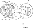
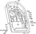
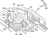
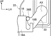
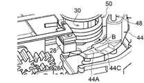
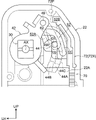
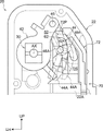
- FIG. 1 It is a front view which shows the fuel lid assembly configured including the fuel lid opener which concerns on one Embodiment of this disclosure, and is the figure which shows the open state of a fuel lid. It is a perspective view which shows the fuel lid opener as seen from the side where the arm part of a lifter is arranged. It is a perspective view which shows the fuel lid opener as seen from the side opposite to FIG. It is a perspective view which shows the case of a fuel lid opener. It is a perspective view which shows the structure in which the moving body is arranged in the case of FIG. 4 in the state when the motor is not operated. It is a perspective view which shows the structure which arranged the moving body in the case of FIG. 4 in the state after movement at the time of motor operation. FIG.
- FIG. 3 is a perspective view showing a part of the fuel lid opener of FIG. 3 with the cover removed.
- FIG. 3 is a perspective view showing a part of the fuel lid opener of FIG. 3 with the cover removed and viewed in a different direction from that of FIG. 6A.
- FIG. 3 is a perspective view showing a part of the fuel lid opener of FIG. 3 in a state where a micro switch is pushed in and in the same directional view as in FIG. 6A.
- It is a perspective view which shows a part of the fuel lid opener of FIG. 3 in a state where a micro switch is pushed and is seen in the same direction as FIG. 6B.
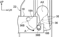
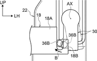
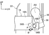
- It is a side view which shows the state of the arm part when the fuel lid is in an open state.
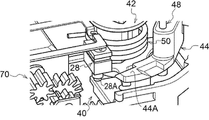
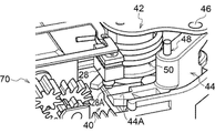
- FIG. 8A It is a side view which shows the state of the arm part when the fuel lid is pushed in from the open state to the pushed state. It is a side view which shows the state of the arm part when the fuel lid is in a closed state. It is a figure which shows the part of the inside of the fuel lid opener when the fuel lid is in an open state, as seen from the side opposite to FIG. 8A. It is a figure which shows the part of the inside of the fuel lid opener when the fuel lid is in the pushed state, as seen from the side opposite to FIG. 8B. It is a figure which shows the part of the inside of the fuel lid opener when the fuel lid is in a closed state, as seen from the side opposite to FIG. 8C.
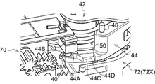
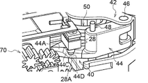
- FIG. 8A It is a figure which shows the part of the inside of the fuel lid opener when the fuel lid is in an open state, as seen from the side opposite to FIG. 8A. It is a figure which shows the part of the inside of the fuel lid opener when the fuel lid is in the pushed state, as
- FIG. 9 is a perspective view of a part of the inside of the fuel lid opener in the same state as in FIG. 9A.
- 9 is a perspective view of a part of the inside of the fuel lid opener in the same state as in FIG. 9B.
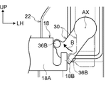
- FIG. 9 is a perspective view of a part of the inside of the fuel lid opener in the same state as in FIG. 9C. It is a side view which shows the state of the arm part when the fuel lid is pushed in from the closed state to the pushed state. It is a side view which shows the state of the arm part when the fuel lid changes from a closed state to an open state.
- FIG. 12A is a diagram showing a state in which the drive unit is operated in the state of FIG. 12A and a part of the moving body is in contact with the second link.
- FIG. 12B is a diagram showing a state in which the lifter is rotated by the urging force of the torsion spring after the state shown in FIG. 12B.
- FIG. 12 is a perspective view of a part of the inside of the fuel lid opener in the same state as in FIG. 12A.
- FIG. 12B is a perspective view of a part of the inside of the fuel lid opener in the same state as in FIG.
- FIG. 12 is a perspective view of a part of the inside of the fuel lid opener in the same state as in FIG. 12C. It is an enlarged figure which shows the support state of the guided part in the closed state of a fuel lid. It is a figure which shows the state which the guided part is removed from the state of FIG. It is a figure which shows the state change of a fuel lid and the change of a signal output from a switch.
- the fuel lid opener 20 according to the embodiment of the present disclosure will be described with reference to FIGS. 1 to 16.
- the arrows FR, UP, and LH appropriately shown in the drawing indicate the front, upper, and left sides (inside in the vehicle width direction) of the vehicle provided with the fuel lid opener 20, respectively.
- the front / rear / left / right / up / down directions the front / rear in the front / rear direction of the vehicle, the left / right in the left / right direction of the vehicle, and the up / down in the up / down direction of the vehicle shall be indicated unless otherwise specified.
- some reference numerals may be omitted in order to make the drawings easier to see.
- the fuel lid opener 20 is a component of the fuel lid assembly 10.
- the fuel lid assembly 10 is attached to a right side portion (for example, a quarter panel) of a vehicle such as an automobile and constitutes a part of a fuel supply portion.
- the fuel lid assembly 10 includes a lid box 12, a fuel lid 14 rotatably supported by the lid box 12 for opening and closing, and a fuel lid opener 20 attached to the lid box 12.
- the configuration is symmetrical with that of the present embodiment.
- the lid box 12 is formed of, for example, sheet metal, and has a box shape in which the outside in the vehicle width direction (here, the right side of the vehicle) is open.
- the lid box 12 has a side wall 12A and a bottom wall 12B, and the side wall 12A is composed of an upper wall 12A1, a lower wall 12A2, a rear wall 12A3, and a front wall 12A4.
- a fuel supply port 12H is formed on the bottom wall 12B.
- a fuel supply pipe (not shown) is connected to the fuel supply port 12H.
- the vehicle according to the present embodiment is a gasoline vehicle or a diesel vehicle. However, when this vehicle is a fuel cell vehicle, a hydrogen filling port is connected to the lid box 12, and when this vehicle is an electric vehicle, the lid is used.
- a charging port is connected to the box 12.
- the fuel lid 14 is formed in a disk shape, for example, by sheet metal.
- a hinge portion 16 extends from a part of the outer periphery of the fuel lid 14.
- the hinge portion 16 is rotatably attached to the front end portion of the lid box 12 via a hinge shaft (not shown) whose axial direction is the vehicle vertical direction.
- the fuel lid 14 has an open position (position shown in FIG. 1) for opening the opening 12K of the lid box 12 and a closed position 14Y (imaginary line (dashed-dotted line) in the figure) for closing the opening 12K of the lid box 12. ) Is rotatable with respect to the lid box 12. In the state where the fuel lid 14 is located at the closed position 14Y (closed state), the hinge portion 16 is arranged at the front end portion of the fuel lid 14.
- a lifter engaging portion 18 is provided at a portion of the fuel lid 14 near the end opposite to the hinge portion 16, that is, a portion near the rear end of the fuel lid 14 in the closed state.
- the lifter engaging portion 18 is formed of, for example, sheet metal, and is fixed to the back surface 14A of the fuel lid 14 by means such as welding.
- the lifter engaging portion 18 projects from the back surface 14A of the fuel lid 14 along the plate thickness direction of the fuel lid 14.
- the lifter engaging portion 18 has a pressing portion 18A extending in a substantially rectangular shape from its base end portion and an L extending upward so as to extend from the lower end portion on the distal end side of the pressing portion 18A. It is integrally provided with a character-shaped engaged portion 18B.
- the lifter engaging portion 18 is provided so as to correspond to the lifter 30 (details will be described later) of the fuel lid opener 20.
- the fuel lid opener 20 includes the case 22 and the cover 24 shown in FIGS. 2 and 3, and also has a lifter 30 shown in FIG. 2 and a push lifter mechanism 38 shown in FIG.
- the case 22 is formed of, for example, a synthetic resin, and has a shallow-bottomed box shape.
- the case 22 is attached to the outer peripheral surface of the side wall 12A of the lid box 12 shown in FIG. 1 (here, the rear surface of the rear wall 12A3) by a fixing means such as screwing.
- the case 22 shown in FIGS. 2 and 3 is open toward the rear side of the vehicle.
- the opening of the case 22 is closed by the cover 24.
- the cover 24 is formed in a plate shape by, for example, synthetic resin, and is attached to the case 22 by means such as claw fitting.
- one micro switch 28 as a switch portion is fixed to an intermediate portion in the vertical direction on the inner surface thereof. That is, the micro switch 28 is arranged in the case 22 in a fixed state. As shown in FIGS. 7A and 7B, the operation unit 28A of the microswitch 28 is projected toward the bottom wall 22A of the case 22 so as to be movable in the projecting direction and the opposite direction.
- the operation unit 28A of the micro switch 28 may be referred to as an actuator unit.
- the micro switch 28 is a normally closed switch as an example, and is configured to output an ON signal when the operation unit 28A is not pressed and to output an OFF signal when the operation unit 28A is pressed. ..
- the microswitch 28 is connected to the wiring 29 fixed to the cover 24.
- the front surface of the bottom wall 22A of the case 22 shown in FIG. 2 is overlapped with the rear surface (not shown) of the rear wall 12A3 of the lid box 12 shown in FIG. 1, and the rear wall 12A3 has the bottom of the case 22.
- a rectangular through hole (not shown) is formed at a position overlapping a part of the wall 22A (see FIG. 2).
- a sealing member 26 formed in a rectangular frame shape by, for example, rubber is sandwiched between the edge of the through hole and the bottom wall 22A of the case 22 shown in FIG.
- FIG. 4 shows a perspective view of the case 22.
- a cylindrical bearing portion 22B is formed on the upper portion of the bottom wall 22A of the case 22.
- the bearing portion 22B is arranged with the vehicle front-rear direction as the axial direction, and in the closed state of the fuel lid 14 (see FIG. 1), the axis AX of the bearing portion 22B is in the plate surface direction of the fuel lid 14 (see FIG. 1). That is, it is configured to follow the direction along the plate surface).
- the inside of the bearing portion 22B is a bearing hole (reference numeral omitted) penetrating the bottom wall 22A of the case 22.
- the bearing portion 22B corresponds to the shaft portion 32 on the upper part of the lifter 30 shown in FIG.
- the lifter 30 is formed of, for example, a synthetic resin, and includes a cylindrical shaft portion 32 and an arm portion 36 extending in the radial direction of the shaft portion 32 from one end portion in the axial direction of the shaft portion 32. ..
- the portion on the one end side in the axial direction of the shaft portion 32 is a large diameter portion (reference numeral omitted), and the portion on the other end side in the axial direction of the shaft portion 32 is a small diameter portion having a smaller diameter than the portion on the one end side in the axial direction of the shaft portion 32. (Not shown).
- the small diameter portion is inserted inside the bearing portion 22B (see FIG.
- the lifter 30 is rotatably supported around the axis AX of the bearing portion 22B (see FIG. 4) with respect to the case 22.
- the stepped surface (not shown) between the large diameter portion and the small diameter portion of the shaft portion 32 is in contact with the contact surface 22C formed on the front surface side of the case 22 from the vehicle front side, and is a lifter for the case 22. The displacement of 30 to the rear side of the vehicle is restricted.
- the link mounting portion 32C shown in FIG. 3 is formed at the other end of the shaft portion 32 in the axial direction.
- the link mounting portion 32C includes upper and lower pairs of block portions 32C1 and 32C2 when viewed from the direction along the axis AX of the shaft portion 32, and has a structure in which the base end side thereof is connected.
- a substantially circular insertion portion 32H is formed in the central portion of the shaft portion 32 when viewed from the direction along the axis AX.
- the insertion portion 32H extends along the axis AX of the shaft portion 32.
- a columnar protrusion 24T formed on the cover 24 is inserted into the insertion portion 32H and is fitted so as to be relatively rotatable. As a result, the shaft portion 32 of the lifter 30 is also supported by the cover 24.
- the arm portion 36 of the lifter 30 shown in FIG. 1 extends in the direction of the turning radius of the lifter 30 (here, the lower side of the vehicle) in the lid box 12, and has a vehicle width with respect to the back surface 14A of the fuel lid 14 in the closed state. They are arranged so as to face each other from the inside of the direction.
- the tip (lower end) of the arm 36 is displaced inward in the vehicle width direction when the lifter 30 rotates in one direction (arrow A direction) around the axis AX, and the lifter 30 is the axis. When it rotates in the other direction around AX (in the direction of arrow B), it is displaced outward in the vehicle width direction.
- a pressed portion 36A protruding toward the outside in the vehicle width direction (here, the right side of the vehicle) is provided at the tip of the arm portion 36 of the lifter 30.
- the tip surface (outer surface in the vehicle width direction) of the pressed portion 36A is an arc surface curved in an arc shape when viewed from the front-rear direction of the vehicle.
- a columnar engaging portion 36B is formed so as to project on the front surface side of the pressed portion 36A.
- the engaging portion 36B is arranged with the direction along the rotation axis AX of the lifter 30 as the axial direction, and is one side of the pressed portion 36A (the tip end portion of the arm portion 36) in the direction along the axis AX.
- the engaging portion 36B and the pressed portion 36A are arranged side by side in the direction along the axis AX. Then, when the surface side of the fuel lid 14 (see FIG. 1) is pressed, the engaging portion 36B of the lifter 30 receives pressing pressure from the pressing portion 18A of the fuel lid 14 (see FIG. 1), so that the arm of the lifter 30 is armed. The portion 36 receives a force to rotate in one direction (direction of arrow A) around the axis AX (see FIGS. 8B and 11A).
- the lifter 30 having the above configuration is provided corresponding to the push lifter mechanism 38 provided in the case 22 shown in FIG.
- the push lifter mechanism 38 includes a first link 42, a first link pin 46, a second link 44 provided with a second link pin 48, and a torsion spring 50 as an urging member.
- a cam groove 52 (see FIG. 4) formed in the bottom wall 22A of the case 22.
- the first link 42 is formed by, for example, press-molding a sheet metal, and is a pair of flat plate portions 42A and 42B facing each other in the rotation axis AX direction of the lifter 30. It has a substantially U-shaped (substantially U-shaped) bent plate shape.
- a through hole 42H (the through hole of the flat plate portion 42B is not shown) is formed on one end side of the pair of flat plate portions 42A and 42B when viewed from the direction along the rotation axis AX of the lifter 30.
- the link mounting portion 32C of the lifter 30 is fitted in the through hole 42H.
- the first link 42 is attached to the lifter 30, and the displacement of the lifter 30 toward the vehicle front side with respect to the case 22 is regulated by the first link 42.
- a torsion spring 50 is arranged between the pair of flat plate portions 42A and 42B on the outer peripheral side of the link mounting portion 32C of the lifter 30.
- the torsion spring 50 is arranged coaxially with the rotation axis AX of the lifter 30.
- One end 50A of the torsion spring 50 shown in FIG. 6A is locked to a spring locking portion 42C continuously formed on the flat plate portion 42A of the first link 42.
- the other end 50B of the torsion spring 50 shown in FIG. 6B is attached to the case 22.
- the torsion spring 50 urges the lifter 30 shown in FIG. 6A toward the other side (direction of arrow B) around the axis AX, and the fuel lid 14 (see FIG. 1) is pushed in from the closed state.
- a spiral spring or a mainspring may be used instead of the torsion spring 50.
- the second link 44 is formed of, for example, a synthetic resin.
- the second link 44 includes a second link main body 44H to which one end is connected to the first link 42, and an extension 44E extending from the other end of the second link main body 44H.
- the second link main body 44H has an elongated shape when viewed from the direction along the rotation axis AX of the lifter 30, and the distance between the pair of flat plate portions 42A and 42B in the direction along the rotation axis AX of the lifter 30. It has a thickness of slightly shorter length than.
- One end of the second link body 44H and the other end of the first link 42 are connected so as to be relatively rotatable by the first link pin 46, and the first link pin 46 is connected to the rotation axis AX of the lifter 30. It is arranged with the parallel direction as the axial direction. As a result, the second link 44 is rotatably connected to the first link 42 around an axis parallel to the rotation axis AX.
- a second link pin (an element that can also be grasped as a "cam pin") 48 is fixed to the other end of the second link main body 44H.
- the second link pin 48 is arranged with the direction parallel to the rotation axis AX of the lifter 30 as the axis direction.
- the guided portion 48A (see FIGS. 13B, 14 and 15) protruding toward the bottom wall 22A of the case 22 in the second link pin 48 is a cam groove 52 (see FIG. 4) formed in the bottom wall 22A of the case 22. ), And can be moved along the cam groove 52.
- the extending portion 44E of the second link 44 extends in an arm shape from the portion on the bottom wall 22A side (front side of the vehicle) at the other end of the second link main body 44H.
- the extending portion 44E of the second link 44 has a substantially arc shape when viewed from the direction along the rotation axis AX of the lifter 30, and the micro switch 28 is in the closed state when the fuel lid 14 (see FIG. 1) is in the closed state.
- the operation unit 28A (both see FIGS. 7A and 7B) is provided with a planar operation pressing unit 44A for pressing the operation unit 28A.
- the operation pressing portion 44A is formed at a portion on the extending direction tip end side of the extending portion 44E of the second link 44, and is arranged with a surface including the vehicle vertical direction and the vehicle width direction as the surface direction.
- the extension portion 44E of the second link 44 has a first inclined surface 44B formed so as to be continuously ascended to the operation pressing portion 44A side at the inner end portion of the operation pressing portion 44A in the vehicle width direction.
- the second inclined surface 44C which is provided separately from the first inclined surface 44B and is formed so as to be continuously inclined upward to the operation pressing portion 44A side at the end portion on the vehicle upper side of the operation pressing portion 44A.
- a concave bottom portion 44D recessed one step with respect to the operation pressing portion 44A is continuously formed at the end portion of the second inclined surface 44C on the side opposite to the operation pressing portion 44A side.
- the concave bottom portion 44D is configured so as not to press the operation portion 28A even if the microswitches 28 shown in FIGS. 7A and 7B are arranged at opposite positions.
- the cam groove 52 has a heart shape when viewed from the direction along the rotation axis AX of the lifter 30 with the direction along the rotation axis AX of the lifter 30 as the depth direction. It has a shape with a part (here, an inverted heart shape) cut out, and opens toward the rear side of the vehicle. As shown in the partially enlarged view of FIG. 4, the cam groove 52 extends from the first groove portion 52A extending substantially in the vertical direction of the vehicle and the upper end portion of the first groove portion 52A to the outside in the vehicle width direction and then extends to the lower side of the vehicle.
- a second groove portion 52B forming a substantially R-shaped corner portion, and a third groove portion 52C extending downward from the lower end portion of the second groove portion 52B to the lower side of the vehicle.
- An island portion 62 projecting to the rear side of the vehicle is formed between the first groove portion 52A and the portion outside the second groove portion 52B in the vehicle width direction.
- the lower surface of the island portion 62 has a non-concave receiving surface 62A.
- the portion of the upper portion of the third groove portion 52C on the inner side in the vehicle width direction is cut out so as to lead to the space on the lower side of the island portion 62.
- a base portion 52D slightly convex toward the rear side of the vehicle from the bottom wall 22A of the case 22 is formed.
- the above-mentioned guided portion 48A is inserted in the cam groove 52.
- the tip of the guided portion 48A is pressed against the bottom surface of the cam groove 52.
- the receiving surface 62A of the island portion 62 described above is orthogonal to the axis AX with respect to the guided portion 48A when the operating portion 28A of the micro switch 28 (both refer to FIG. 7B) is pressed by the operating pressing portion 44A. It is set to make contact on one side (here, the upper side) in the direction of contact.
- the operating portion 28A of the micro switch 28 both refer to FIG. 7B
- the cam groove 52 has an inclined surface formed on the bottom surface of the first groove portion 52A and the bottom surface of the second groove portion 52B, and the bottom surface of the first groove portion 52A and the second groove portion 52B.
- a step is formed between the bottom surface of the second groove portion 52B and the bottom surface of the third groove portion 52C, and between the bottom surface of the third groove portion 52C and the surface of the base portion 52D.
- the drive unit 70 includes a moving body 72 arranged outside in the vehicle width direction in the case 22, and a motor 74 as a driving source arranged inside the vehicle width direction with respect to the lower portion of the moving body 72.
- the motor 74 is fixed to the lower part of the case 22.
- a rotary gear 76A is attached to the output shaft of the motor 74.
- a rotary gear group 76 including a rotary gear 76A is provided for transmitting the driving force of the motor 74, and the final rotary gear in the rotary gear group 76 is a pinion gear 76P.
- FIG. 5A is a perspective view showing a structure in which the moving body 72 is arranged in the case 22.
- the moving body 72 shown in FIG. 5A is formed of, for example, a synthetic resin, and is supported by a case 22 so as to be movable in the vertical direction. More specifically, FIG. 5A is a position in which the moving body 72 restricts the operation of the second link 44 when the operation unit 28A of the micro switch 28 shown in FIG. 7A is pressed by the operation pressing unit 44A. It is possible to move between the regulation position 72X shown in the above and the regulation release position 72Y shown in FIG. 5B for releasing the restriction.
- Rack teeth 72A are formed side by side on the rear surface of the lower part of the moving body 72.
- the pinion gear 76P (see FIG. 3) is meshed with the rack teeth 72A. Then, the moving body 72 is moved from the restricted position 72X shown in FIG. 5A to the restricted release position 72Y shown in FIG. 5B by the operation of the motor 74 (see FIG. 3).
- the motor 74 shown in FIG. 3 is connected to a control unit 80 (in the figure, only the outer line is schematically shown by a two-dot chain line), and is controlled by the control unit 80.
- the moving body 72 has a long extension portion 72H extending in a long shape from the lower portion thereof to the upper side of the vehicle and a vehicle branched from the lower side of the long extension portion 72H. It is provided with an L-shaped branch portion 72L that extends inward in the width direction and then extends toward the upper side of the vehicle.
- the lower portion 72B of the long extension portion 72H extends in the vertical direction of the vehicle.
- the upper portion 72C of the long extension portion 72H is slightly inclined inward in the vehicle width direction toward the upper side of the vehicle.
- a protruding wall portion 72D protruding to the rear side of the vehicle is formed in the upper portion 72C of the long extending portion 72H and a portion on the outer side in the vehicle width direction in the vicinity thereof.
- a long piece 72E extends in a cantilevered state from a portion of the lower end of the protruding wall portion 72D on the rear side of the vehicle toward the lower side of the vehicle, and the lower end of the long piece 72E is outside in the vehicle width direction.
- a locking convex portion 72K protruding from the surface is integrally formed. As shown in FIG. 5A, when the moving body 72 is arranged at the restricted position 72X, the locking convex portion 72K is formed in the first locking recess 22X formed on the inner surface of the side wall on the outer side in the vehicle width direction of the case 22. Locked. Further, as shown in FIG.
- the locking convex portion 72K is the second locking formed on the inner surface of the side wall on the outer side in the vehicle width direction of the case 22. It is locked in the recess 22Y.
- an extruded portion 72P protruding toward the second link 44 is formed at the upper end portion of the protruding wall portion 72D.
- the extruded portion 72P uses the guided portion 48A as a receiving surface of the cam groove 52 as shown in FIG. 15 when the moving body 72 moves from the restricted position 72X shown in FIG. 5A to the restricted release position 72Y shown in FIG. 5B.
- the second link 44 is pushed out so as to be removed from 62A inward in the vehicle width direction.
- the upper portion of the branch portion 72L of the moving body 72 is provided with a stopper portion 72S protruding toward the rear side of the vehicle.
- the stopper portion 72S is configured to be adjacent to a portion on the inner surface of the lower surface of the island portion 62 in the vehicle width direction (left side in the figure) when the moving body 72 is arranged at the restricted position 72X. That is, as shown in FIG. 14, the stopper portion 72S is the guided portion 48A when the moving body 72 is arranged at the restricted position 72X to restrict the operation of the second link 44 when viewed from the direction along the axis AX.
- the stopper portion 72S is arranged at a position where it cannot contact the guided portion 48A.
- the push lifter mechanism 38 shown in FIG. 3 rotates the lifter 30 shown in FIG. 2 in the other direction (direction of arrow B) around the axis AX by operating the drive unit 70 to provide the fuel lid 14 shown in FIG. It is configured to push open.
- a specific description will be given.
- the push lifter mechanism 38 shown in FIG. 3 is provided with a contact / detachment switching mechanism 40 that is operated by the rotation of the lifter 30 to be brought into contact with and detached from the operation unit 28A (see FIG. 7A and the like) of the micro switch 28.
- the contact / detachment switching mechanism 40 includes a first link 42, a first link pin 46, a second link 44 provided with a second link pin 48, a torsion spring 50, a cam groove 52 (see FIG. 4), and a drive unit 70. It is a mechanism part that exerts a function of connecting and detaching from the operation unit 28A (see FIG. 7A and the like) of the micro switch 28 by using it.
- the contact / detachment switching mechanism 40 returns to the closed state from the open state to the closed state and the pushed state (the state of being pushed in rather than the closed state) of the fuel lid 14 (see FIG. 1) (FIGS. 8A, 8B, 8C).
- the signal output from the micro switch 28 (see FIG. 3) is switched from the ON signal as the first signal to the OFF signal as the second signal by performing the predetermined first operation. (See FIG. 16).
- the operation unit 28A of the micro switch 28 shown in FIGS. 7A and 7B changes the viewing direction in the order of FIGS. 9A, 9B, and 9C when the contact / detachment switching mechanism 40 performs the first operation.
- FIG. 10B, and FIG. 10C Is configured to move relative to each other.
- the first inclined surface 44B of the second link 44 described above is set to gradually press the operation unit 28A of the micro switch 28 at the end of the first operation of the contact / detachment switching mechanism 40.
- the contact / detachment switching mechanism 40 is used when the fuel lid 14 (see FIG. 1) returns from the closed state to the closed state through the pushed state (the lifter 30 in FIG. 11A passes from the position of the alternate long and short dash line to the position of the alternate long and short dash line.
- the signal output from the micro switch 28 can be switched in the order of OFF signal, ON signal, and OFF signal by performing a predetermined second operation different from the first operation. (See FIG. 16).
- the operation unit 28A of the micro switch 28 shown in FIGS. 7A and 7B changes the viewing direction in the order of FIGS.
- FIG. 10C, FIG. 13A, and FIG. 10C Is configured to move relative to each other.
- the second inclined surface 44C of the second link 44 described above is set to gradually press the operation unit 28A of the micro switch 28 at the end of the second operation of the contact / detachment switching mechanism 40.
- FIG. 2 shows that the control unit 80 shown in FIG. 3 operates the motor 74 on condition that the signal output from the micro switch 28 is switched in the order of the OFF signal, the ON signal, and the OFF signal within a predetermined time.
- the drive unit 70 shown in FIG. 3 is operated so that the lifter 30 shown is rotated in the other direction (direction of arrow B) around the axis AX (moving body 72 is shown from the restricted position 72X shown in FIGS. 9C and 10C). 12B and move to the regulation release position 72Y shown in FIG. 13B). More specifically, in the present embodiment, in the control unit 80 shown in FIG. 3, the signal output from the micro switch 28 is switched from the OFF signal to the ON signal and then to the OFF signal within a predetermined time.
- the lifter 30 shown in FIG. 2 is rotated to the other side (arrow B direction) around the axis AX.
- the drive unit 70 shown in FIG. 3 is operated so as to be operated.
- FIG. 14 the operation of the drive unit 70 will be described in FIG. 14 in which the push lifter mechanism 38 is in a position where it cannot be moved by the urging force of the torsion spring 50 when the fuel lid 14 (see FIG. 1) is pushed open.
- the guided portion 48A shown is at that position (the urging force of the torsion spring 50) by the driving force of the driving portion 70 (ie, by the extruded portion 72P of the moving body 72 pushing the second link 44) as shown in FIG.
- the lifter 30 is moved through the first link 42 via the first link 42 by the urging force of the torsion spring 50 (see FIG. 3) (in the direction of arrow B). ) Is configured to rotate.
- FIG. 11B is a view of the state of FIG. 12C as viewed from the opposite side of the case 22, and FIG. 13C is a perspective view showing the state of FIG. 12C in a different direction. Further, in the state shown in FIG. 12C, an ON signal is output from the micro switch 28.
- the fuel lid 14 is rotatably supported in the lid box 12 shown in FIG. 1 for opening and closing, and is shown on the outer peripheral surface (rear surface of the rear wall 12A3) of the side wall 12A of the lid box 12.
- the case 22 shown in 2 is attached.
- the lifter 30 is rotatably supported on the case 22 around the axis AX along the plate surface direction of the fuel lid 14 (see FIG. 1) in the closed state.
- the arm portion 36 of the lifter 30 extends in the radius of rotation in the lid box 12 (see FIG. 1) and rotates in one direction (arrow A direction) around the axis AX when the front surface side of the fuel lid 14 is pressed. Receive power. Further, as shown in FIG.
- a push lifter mechanism 38 is provided in the case 22, and the torsion spring 50 of the push lifter mechanism 38 urges the lifter 30 to the other side (direction of arrow B) around the axis AX.
- the push lifter mechanism 38 rotates the lifter 30 in the other direction (direction of arrow B) around the axis AX by operating the drive unit 70, and pushes the fuel lid 14 open.
- the push lifter mechanism 38 is provided with a contact / detachment switching mechanism 40, which is operated by the rotation of the lifter 30 with the operation unit 28A of the micro switch 28 (see FIG. 7A and the like). Get in and out.
- the contact / detachment switching mechanism 40 performs a predetermined first operation when the fuel lid 14 returns from the open state to the closed state and the closed state, and the signal output from the micro switch 28 is an ON signal. It is configured to switch from to to OFF signal (see FIG. 16). Further, in the contact / detachment switching mechanism 40, when the fuel lid 14 returns from the closed state to the closed state through the pushed state, the signal output from the micro switch 28 is output by performing a predetermined second operation different from the first operation.
- the control unit 80 uses the lifter 30 on the other side (direction of arrow B) around the axis AX, at least on condition that the signal output from the micro switch 28 is switched in the order of the OFF signal, the ON signal, and the OFF signal within a predetermined time.
- the drive unit 70 is operated so as to rotate to. Therefore, even if the fuel lid (see FIG. 1) is slowly pressed from the open state, malfunction can be prevented.
- control unit 80 shown in FIG. 3 when the signal output from the micro switch 28 is switched in the order of the OFF signal, the ON signal, and the OFF signal within a predetermined time, and the first OFF signal thereof is used.
- the drive unit 70 shown in FIG. 3 is such that the lifter 30 shown in FIG. 2 is rotated to the other side (direction of arrow B) around the axis AX when it is determined that the output is continuously performed for a preset reference time or longer.
- the operation of the motor 74 is executed at the moment when the fuel lid 14 returns from the closed state to the closed state through the pushed state and the signal output from the micro switch 28 becomes an OFF signal.
- the signal output from the micro switch 28 is immediately switched from the OFF signal to the ON signal (see FIG. 16) after the operation of the motor 74, the output duration of the OFF signal can be set. Even if it is controlled based on the reference, malfunction can be prevented.
- the switch portion is composed of one micro switch 28 arranged in a fixed state in the case 22, and the contact / detachment switching mechanism 40 performs the first operation and the contact / detachment switching mechanism 40.
- the switch portion is composed of one micro switch 28 arranged in a fixed state in the case 22, and the contact / detachment switching mechanism 40 performs the first operation and the contact / detachment switching mechanism 40.
- the push lifter mechanism 38 has a cam groove 52 (see FIG. 4), a first link 42, and a second link 44.
- the cam groove 52 shown in FIG. 4 is provided in the case 22 and has a depth direction along the direction of the axis AX, and the first link 42 shown in FIG. 3 is attached to the lifter 30.
- the second link 44 is rotatably connected to the first link 42 around an axis parallel to the axis AX, and the operation pressing portion 44A (see FIG. 6A) and the guided portion 48A (see FIG. 14). ) Is provided.
- the push lifter mechanism 38 shown in FIG. 3 has a guided portion 48A shown in FIG. 14 which is in a position where the fuel lid 14 cannot be moved by the urging force of the torsion spring 50 when the fuel lid 14 is pushed open.
- the torsion spring 50 (see FIG. 3) is displaced from the position by the driving force of the driving unit 70 (that is, by pushing the second link 44 by the extruded unit 72P of the moving body 72).
- the lifter 30 is rotated by the urging force in the other direction (direction of arrow B) around the axis AX via the first link 42. In this way, the fuel lid 14 can be opened by using the driving force of the driving unit 70 and the urging force of the torsion spring 50.
- the first inclined surface 44B of the second link 44 shown in FIG. 7A is formed so as to be continuously inclined upward to the operation pressing portion 44A side of the operation pressing portion 44A, and the contact / separation switching is performed.
- the operation unit 28A of the micro switch 28 is gradually pressed. Therefore, although the configuration is relatively simple, the signal output from the micro switch 28 can be stably switched at the end of the first operation of the contact / detachment switching mechanism 40.
- the second inclined surface 44C of the second link 44 shown in FIG. 7B is provided separately from the first inclined surface 44B so as to be continuously inclined to the operation pressing portion 44A toward the operation pressing portion 44A.
- the operation unit 28A of the micro switch 28 is gradually pressed at the end of the second operation of the contact / detachment switching mechanism 40. Therefore, although the configuration is relatively simple, the signal output from the micro switch 28 can be stably switched at the end of the second operation of the contact / detachment switching mechanism 40.
- the non-concave receiving surface 62A of the cam groove 52 is covered as shown in FIG. It contacts the upper end side of the guide portion 48A.
- the moving body 72 of the drive unit 70 shown in FIG. 7A or the like is a position that restricts the operation of the second link 44 when the operation unit 28A of the micro switch 28 is pressed by the operation pressing unit 44A. It is possible to move between the regulation release position 72X shown in the above and the regulation release position 72Y shown in FIG. 5B, and the regulation release position 72Y is moved from the regulation position 72X by the operation of the motor 74 (see FIG. 3). Moved to.
- the stopper portion 72S of the moving body 72 is guided from a direction along the axis AX when the moving body 72 is arranged at the restricted position 72X to restrict the operation of the second link 44. It is arranged inside the vehicle width direction with respect to the portion 48A and restricts the movement of the guided portion 48A. Further, the stopper portion 72S of the moving body 72 is arranged at a position where it cannot contact the guided portion 48A when the moving body 72 is arranged at the restriction release position 72Y (see FIG. 5B). Further, as shown in FIG. 15, the extruded portion 72P of the moving body 72 moves the guided portion 48A to the cam groove 52 when the moving body 72 moves from the restricted position 72X (see FIG. 14) to the restricted release position 72Y. The second link 44 is pushed out so as to be removed from the receiving surface 62A inward in the vehicle width direction.
- the guided portion 48A moves as shown in FIG.
- the moving body 72 is stably regulated by the receiving surface 62A and the stopper portion 72S and the moving body 72 moves from the restricted position 72X to the restricted release position 72Y (see FIG. 12B) by the driving force of the motor 74 (see FIG. 3)
- FIG. The guided portion 48A shown in 15 can be easily removed from the receiving surface 62A of the cam groove 52.
- the fuel lid opener 20 of the present embodiment it is possible to prevent malfunction when the fuel lid 14 is slowly pressed from the open state.
- the switch unit is composed of one micro switch 28 shown in FIG. 3 and the like, but the switch unit may be composed of a plurality of switch elements.
- the push lifter mechanism 38 has a cam groove 52, a first link 42, and a second link 44, but the configuration of the push lifter mechanism is limited to such a configuration. is not.
- the driven force of the drive unit 70 removes the guided portion 48A shown in FIG. 15 from the receiving surface 62A, and then the urging force of the torsion spring 50 as an urging member.
- the structure of the push lifter mechanism is not limited to such a structure.
- the cam groove 52 has the non-concave receiving surface 62A and the moving body 72 has the stopper portion 72S.
- a concave concave receiving surface is set and a stopper is provided. It is also possible to adopt a configuration in which the portion 72S is not provided.
- the second link 44 has the first inclined surface 44B and the second inclined surface 44C, and the configuration of the second link is such a configuration. Not limited to.
- control unit 80 shown in FIG. 3 is a case where the signal output from the micro switch 28 is switched in the order of the OFF signal, the ON signal, and the OFF signal within a predetermined time, and the first OFF signal thereof. Is operating the drive unit 70 when it is determined that the output has been continuously output for the preset reference time or longer, but it is determined that "the first OFF signal has been continuously output for the preset reference time or longer". It is also possible to adopt a configuration that excludes "case” from the conditions.
- the present invention is not limited to the above, and it is needless to say that the present invention can be variously modified and implemented within a range not deviating from the gist thereof. ..
Landscapes
- Engineering & Computer Science (AREA)
- Mechanical Engineering (AREA)
- Chemical & Material Sciences (AREA)
- Combustion & Propulsion (AREA)
- Transportation (AREA)
- Life Sciences & Earth Sciences (AREA)
- Sustainable Development (AREA)
- Sustainable Energy (AREA)
- Cooling, Air Intake And Gas Exhaust, And Fuel Tank Arrangements In Propulsion Units (AREA)
Abstract
Description
図1に示されるように、本実施形態に係るフューエルリッドオープナー20は、フューエルリッドアッセンブリ10の構成要素とされている。フューエルリッドアッセンブリ10は、自動車等の車両の右側部(例えばクォータパネル)に取り付けられ、燃料供給部の一部を構成するものである。このフューエルリッドアッセンブリ10は、リッドボックス12と、開閉用としてリッドボックス12に回動可能に支持されるフューエルリッド14と、リッドボックス12に取り付けられたフューエルリッドオープナー20と、を備えている。なお、フューエルリッドアッセンブリ10が車両の左側部に取り付けられる場合、本実施形態とは左右対称の構成となる。
Claims (7)
- フューエルリッドが開閉用として回動可能に支持されるリッドボックスの側壁の外周面に取り付けられるケースと、
閉状態の前記フューエルリッドの板面方向に沿った軸線回りに回動可能に前記ケースに支持されると共に、前記リッドボックス内で回動半径方向に延びて前記フューエルリッドの表面側が押圧操作された場合に前記軸線回りの一方へ回動させる力を受ける腕部を有するリフタと、
前記ケース内に設けられ、前記リフタを前記軸線回りの他方へ付勢すると共に前記フューエルリッドが前記閉状態よりも押し込まれた押込状態になった場合に前記閉状態の位置に戻すように付勢する付勢部材を有すると共に、駆動部が作動することで前記リフタを前記軸線回りの他方へ回動させて前記フューエルリッドを押し開くプッシュリフタ機構と、
前記プッシュリフタ機構に設けられて前記リフタの回動によって作動してスイッチ部の操作部と接離すると共に、前記フューエルリッドが開状態から前記閉状態及び前記押込状態を経て前記閉状態に戻る場合には所定の第一動作をすることで前記スイッチ部から出力される信号が第一信号から第二信号に切り替えられるように構成され、前記フューエルリッドが前記閉状態から前記押込状態を経て前記閉状態に戻る場合には前記第一動作とは異なる所定の第二動作をすることで前記スイッチ部から出力される信号が前記第二信号から前記第一信号、前記第二信号の順に切り替えられるように構成された接離切替機構と、
前記スイッチ部から出力される信号が前記第二信号から前記第一信号、前記第二信号の順に所定時間内に切り替わったことを少なくとも条件として前記リフタを前記軸線回りの他方へ回動させるように前記駆動部を作動させる制御部と、
を備えたフューエルリッドオープナー。 - 前記スイッチ部は、前記ケース内において固定状態で配置された1個のマイクロスイッチによって構成され、
前記接離切替機構が前記第一動作をした場合と前記接離切替機構が前記第二動作をした場合とでは前記接離切替機構に対する前記マイクロスイッチの操作部の相対移動経路が異なるように構成されている、請求項1記載のフューエルリッドオープナー。 - 前記プッシュリフタ機構は、
前記ケースに設けられて前記軸線の方向に沿った方向を深さ方向とするカム溝と、
前記リフタに取り付けられた第一リンクと、
前記第一リンクに対して前記軸線と平行な軸回りに回動可能に連結されると共に、前記フューエルリッドが前記閉状態にある場合に前記スイッチ部の操作部を押圧する平面状の操作押圧部と、前記カム溝に挿入されて前記カム溝に沿って移動可能な被ガイド部と、を備えた第二リンクと、
を有する、請求項1又は請求項2に記載のフューエルリッドオープナー。 - 前記プッシュリフタ機構は、前記フューエルリッドを押し開く場合に、前記付勢部材の付勢力では移動不能な位置にある前記被ガイド部を、前記駆動部の駆動力によって当該位置から脱出させることで、前記付勢部材の付勢力で前記リフタを前記軸線回りの他方へ回動させるように構成されている、請求項3記載のフューエルリッドオープナー。
- 前記第二リンクは、
前記操作押圧部に連続して前記操作押圧部側へ上り傾斜となるように形成され、前記接離切替機構の前記第一動作の終盤に前記スイッチ部の操作部を徐々に押圧するように設定された第一傾斜面と、
前記第一傾斜面とは別に設けられて前記操作押圧部に連続して前記操作押圧部側へ上り傾斜となるように形成され、前記接離切替機構の前記第二動作の終盤に前記スイッチ部の操作部を徐々に押圧するように設定された第二傾斜面と、
を有する、請求項3又は請求項4に記載のフューエルリッドオープナー。 - 前記カム溝は、前記スイッチ部の操作部が前記操作押圧部によって押圧されている場合に前記被ガイド部に対して前記軸線と直交する方向の一方側において接触する非凹状の受面を有し、
前記駆動部は、駆動源と、前記スイッチ部の操作部が前記操作押圧部によって押圧されている場合に前記第二リンクの作動を規制する位置である規制位置と前記規制を解除する規制解除位置との間で移動可能とされて前記駆動源の作動によって前記規制位置から前記規制解除位置へ移動される移動体と、を有し、
前記移動体は、
前記移動体が前記規制位置に配置されて前記第二リンクの作動を規制する場合に前記軸線に沿った方向から見て前記被ガイド部に対して前記受面が配置される側とは直交する方向の一方側に配置されて前記被ガイド部の移動を規制し、前記移動体が前記規制解除位置に配置される場合には前記被ガイド部と接触不能な位置に配置されるストッパ部と、
前記移動体が前記規制位置から前記規制解除位置へ移動する場合に前記被ガイド部を前記カム溝の前記受面から外すように前記第二リンクを押し出す押出部と、
を備える、請求項3~請求項5のいずれか1項に記載のフューエルリッドオープナー。 - 前記制御部は、前記スイッチ部から出力される信号が前記第二信号から前記第一信号、前記第二信号の順に所定時間内に切り替わった場合でかつその最初の前記第二信号が予め設定した基準時間以上継続して出力されていたと判断した場合に前記リフタを前記軸線回りの他方へ回動させるように前記駆動部を作動させる、請求項1~請求項6のいずれか1項に記載のフューエルリッドオープナー。
Priority Applications (3)
| Application Number | Priority Date | Filing Date | Title |
|---|---|---|---|
| CN202180080108.4A CN116547160A (zh) | 2020-12-07 | 2021-12-06 | 燃料加注口盖开启器 |
| US18/255,580 US20240001760A1 (en) | 2020-12-07 | 2021-12-06 | Fuel lid opener |
| JP2022568271A JP7696090B2 (ja) | 2020-12-07 | 2021-12-06 | フューエルリッドオープナー |
Applications Claiming Priority (2)
| Application Number | Priority Date | Filing Date | Title |
|---|---|---|---|
| JP2020-202902 | 2020-12-07 | ||
| JP2020202902 | 2020-12-07 |
Publications (1)
| Publication Number | Publication Date |
|---|---|
| WO2022124272A1 true WO2022124272A1 (ja) | 2022-06-16 |
Family
ID=81974400
Family Applications (1)
| Application Number | Title | Priority Date | Filing Date |
|---|---|---|---|
| PCT/JP2021/044769 Ceased WO2022124272A1 (ja) | 2020-12-07 | 2021-12-06 | フューエルリッドオープナー |
Country Status (4)
| Country | Link |
|---|---|
| US (1) | US20240001760A1 (ja) |
| JP (1) | JP7696090B2 (ja) |
| CN (1) | CN116547160A (ja) |
| WO (1) | WO2022124272A1 (ja) |
Cited By (1)
| Publication number | Priority date | Publication date | Assignee | Title |
|---|---|---|---|---|
| CN115303062A (zh) * | 2022-08-02 | 2022-11-08 | 东风汽车集团股份有限公司 | 一种车辆控制方法、装置、车辆和介质 |
Families Citing this family (2)
| Publication number | Priority date | Publication date | Assignee | Title |
|---|---|---|---|---|
| DE102021104304A1 (de) * | 2021-02-23 | 2022-08-25 | Illinois Tool Works Inc. | Vorrichtung zum schalten und betätigen mehrerer funktionen eines lade- und/oder tankmuldensystems eines fahrzeugs sowie lade- und/oder tankmuldensystem mit solch einer vorrichtung |
| CN116136140A (zh) * | 2021-11-18 | 2023-05-19 | 伊利诺斯工具制品有限公司 | 用于锁定充电、加油或检修翻盖的锁定装置 |
Citations (4)
| Publication number | Priority date | Publication date | Assignee | Title |
|---|---|---|---|---|
| DE102011012699A1 (de) * | 2011-03-01 | 2012-09-06 | Daimler Ag | Verriegelungseinrichtung zum Verriegeln eines Verschlussorgans und Verfahren zur Steuerung einer Verriegelungseinheit |
| WO2019230924A1 (ja) * | 2018-05-30 | 2019-12-05 | 日本発條株式会社 | フューエルリッドオープナー |
| JP2020037793A (ja) * | 2018-09-03 | 2020-03-12 | 株式会社城南製作所 | 車両用リッドロック装置、車両用リッドロック機構、及び車両用ロック機構 |
| JP2020070564A (ja) * | 2018-10-29 | 2020-05-07 | 株式会社城南製作所 | 車両用リッドロック装置及び蓋開閉機構 |
Family Cites Families (6)
| Publication number | Priority date | Publication date | Assignee | Title |
|---|---|---|---|---|
| US5076622A (en) * | 1990-07-25 | 1991-12-31 | Lectron Products, Inc. | Fuel filler latch assembly |
| DE102004010294B4 (de) * | 2004-03-03 | 2007-05-03 | Itw Automotive Products Gmbh & Co. Kg | Tankmulde für Automobile |
| JP6211909B2 (ja) * | 2013-12-02 | 2017-10-11 | 株式会社ニフコ | リッド装置 |
| KR101567246B1 (ko) * | 2014-10-17 | 2015-11-06 | 현대자동차주식회사 | 액츄에이터 일체형 푸시 오프너 |
| JP6447370B2 (ja) * | 2015-06-03 | 2019-01-09 | 株式会社アンセイ | 車両用の蓋体開閉装置 |
| JP7163112B2 (ja) * | 2018-09-03 | 2022-10-31 | 株式会社城南製作所 | 車両用リッドロック機構、車両用リッドロック装置、及び車両用ロック機構 |
-
2021
- 2021-12-06 US US18/255,580 patent/US20240001760A1/en active Pending
- 2021-12-06 JP JP2022568271A patent/JP7696090B2/ja active Active
- 2021-12-06 CN CN202180080108.4A patent/CN116547160A/zh active Pending
- 2021-12-06 WO PCT/JP2021/044769 patent/WO2022124272A1/ja not_active Ceased
Patent Citations (4)
| Publication number | Priority date | Publication date | Assignee | Title |
|---|---|---|---|---|
| DE102011012699A1 (de) * | 2011-03-01 | 2012-09-06 | Daimler Ag | Verriegelungseinrichtung zum Verriegeln eines Verschlussorgans und Verfahren zur Steuerung einer Verriegelungseinheit |
| WO2019230924A1 (ja) * | 2018-05-30 | 2019-12-05 | 日本発條株式会社 | フューエルリッドオープナー |
| JP2020037793A (ja) * | 2018-09-03 | 2020-03-12 | 株式会社城南製作所 | 車両用リッドロック装置、車両用リッドロック機構、及び車両用ロック機構 |
| JP2020070564A (ja) * | 2018-10-29 | 2020-05-07 | 株式会社城南製作所 | 車両用リッドロック装置及び蓋開閉機構 |
Cited By (1)
| Publication number | Priority date | Publication date | Assignee | Title |
|---|---|---|---|---|
| CN115303062A (zh) * | 2022-08-02 | 2022-11-08 | 东风汽车集团股份有限公司 | 一种车辆控制方法、装置、车辆和介质 |
Also Published As
| Publication number | Publication date |
|---|---|
| CN116547160A (zh) | 2023-08-04 |
| JPWO2022124272A1 (ja) | 2022-06-16 |
| JP7696090B2 (ja) | 2025-06-20 |
| US20240001760A1 (en) | 2024-01-04 |
Similar Documents
| Publication | Publication Date | Title |
|---|---|---|
| WO2022124272A1 (ja) | フューエルリッドオープナー | |
| JP5732795B2 (ja) | 車両用ドアハンドル装置 | |
| CN102052021B (zh) | 门把手行程切换构造 | |
| EP3763904B1 (en) | Door handle device for vehicles | |
| JP4272061B2 (ja) | 自動車のドア用のモジュラーロックおよびこのロックを備えたドア | |
| US10072447B2 (en) | Outer handle device for vehicle door | |
| EP1703048B1 (en) | Vehicle door lock device | |
| US9362670B2 (en) | Charge connector locking apparatus | |
| US7810853B2 (en) | Vehicle door lock | |
| US20140137474A1 (en) | Door actuating apparatus | |
| JP5303902B2 (ja) | 車両ドアロック装置 | |
| WO2010114057A1 (ja) | 可動体の動作機構 | |
| US11560050B2 (en) | Lid opening and closing device | |
| JP2019090255A (ja) | ドアラッチ装置 | |
| KR20120063707A (ko) | 차량용 글로브박스 개폐장치 및 이를 구비하는 글로브박스 조립체 | |
| CN114435120A (zh) | 致动组件及加油口或充电口翻盖组件 | |
| JP2012041764A (ja) | 車両用ドアラッチ装置 | |
| JP2011140811A (ja) | ドアラッチアクチュエータ | |
| CN115929131A (zh) | 包括齿条和小齿轮的用于释放系统的按钮组件 | |
| KR20140096188A (ko) | 자동차용 도어 개폐장치 | |
| JP4619037B2 (ja) | 蓋開閉機構 | |
| CN101144348B (zh) | 作动装置 | |
| JP7749897B2 (ja) | ドアラッチ装置の防水構造 | |
| WO2022185863A1 (ja) | 車両用リッドロック装置、供給部構造及び車両用リッドロック装置の取付け方法 | |
| JP6089294B2 (ja) | 車両用ドアラッチシステム |
Legal Events
| Date | Code | Title | Description |
|---|---|---|---|
| 121 | Ep: the epo has been informed by wipo that ep was designated in this application |
Ref document number: 21903372 Country of ref document: EP Kind code of ref document: A1 |
|
| WWE | Wipo information: entry into national phase |
Ref document number: 202180080108.4 Country of ref document: CN |
|
| ENP | Entry into the national phase |
Ref document number: 2022568271 Country of ref document: JP Kind code of ref document: A |
|
| WWE | Wipo information: entry into national phase |
Ref document number: 18255580 Country of ref document: US |
|
| NENP | Non-entry into the national phase |
Ref country code: DE |
|
| 122 | Ep: pct application non-entry in european phase |
Ref document number: 21903372 Country of ref document: EP Kind code of ref document: A1 |