WO2022118637A1 - 多層フィルムの製造方法 - Google Patents
多層フィルムの製造方法 Download PDFInfo
- Publication number
- WO2022118637A1 WO2022118637A1 PCT/JP2021/041768 JP2021041768W WO2022118637A1 WO 2022118637 A1 WO2022118637 A1 WO 2022118637A1 JP 2021041768 W JP2021041768 W JP 2021041768W WO 2022118637 A1 WO2022118637 A1 WO 2022118637A1
- Authority
- WO
- WIPO (PCT)
- Prior art keywords
- film
- films
- control member
- roller
- position control
- Prior art date
- Legal status (The legal status is an assumption and is not a legal conclusion. Google has not performed a legal analysis and makes no representation as to the accuracy of the status listed.)
- Ceased
Links
Images




Classifications
-
- B—PERFORMING OPERATIONS; TRANSPORTING
- B05—SPRAYING OR ATOMISING IN GENERAL; APPLYING FLUENT MATERIALS TO SURFACES, IN GENERAL
- B05D—PROCESSES FOR APPLYING FLUENT MATERIALS TO SURFACES, IN GENERAL
- B05D1/00—Processes for applying liquids or other fluent materials
- B05D1/34—Applying different liquids or other fluent materials simultaneously
-
- B—PERFORMING OPERATIONS; TRANSPORTING
- B65—CONVEYING; PACKING; STORING; HANDLING THIN OR FILAMENTARY MATERIAL
- B65H—HANDLING THIN OR FILAMENTARY MATERIAL, e.g. SHEETS, WEBS, CABLES
- B65H23/00—Registering, tensioning, smoothing or guiding webs
- B65H23/02—Registering, tensioning, smoothing or guiding webs transversely
- B65H23/032—Controlling transverse register of web
- B65H23/038—Controlling transverse register of web by rollers
-
- B—PERFORMING OPERATIONS; TRANSPORTING
- B65—CONVEYING; PACKING; STORING; HANDLING THIN OR FILAMENTARY MATERIAL
- B65H—HANDLING THIN OR FILAMENTARY MATERIAL, e.g. SHEETS, WEBS, CABLES
- B65H23/00—Registering, tensioning, smoothing or guiding webs
- B65H23/04—Registering, tensioning, smoothing or guiding webs longitudinally
- B65H23/18—Registering, tensioning, smoothing or guiding webs longitudinally by controlling or regulating the web-advancing mechanism, e.g. mechanism acting on the running web
- B65H23/188—Registering, tensioning, smoothing or guiding webs longitudinally by controlling or regulating the web-advancing mechanism, e.g. mechanism acting on the running web in connection with running-web
Definitions
- This disclosure relates to a method for manufacturing a multilayer film.
- Patent Document 1 is characterized in that a plurality of dice are arranged in parallel facing a back roll supporting the support in the width direction of the elongated support to be transported to form a coating layer.
- the coating method is disclosed.
- the multilayer film obtained by the method of applying the coating liquid on the wide film is usually cut according to the width of the product.
- the method of cutting the film after applying the coating liquid may increase the cost required for manufacturing the product.
- an increase in equipment cost associated with the introduction of a process of cutting a film after application of a coating liquid or a loss generated in a downstream process after application of a coating liquid increases the cost required for manufacturing a product.
- a wide film is likely to wrinkle due to heat shrinkage, for example. The above circumstances may lead to a decrease in productivity.
- One aspect of the present disclosure is to provide a method for producing a multilayer film having excellent productivity.
- the disclosure includes the following aspects: ⁇ 1> Simultaneously transporting a plurality of films to a roller including an outer peripheral surface, and applying a coating liquid to the plurality of films transported in parallel on the outer peripheral surface of the roller.
- a method for manufacturing a multilayer film including. ⁇ 2> Detecting the position of one end in the width direction of each film in the plurality of films coated with the coating liquid, and controlling the transport position of each film in the plurality of films according to the position.
- the method for producing a multilayer film according to ⁇ 1> which comprises. ⁇ 3>
- the control of the transport position is such that each film in the plurality of films is arranged with the roller facing the roller in the transport direction of the plurality of films, upstream of the coating position of the coating liquid.
- the method for producing a multilayer film according to ⁇ 2> which comprises changing at least one of the pressure and the angle of the position control member while passing the film between the position control member and the position control member for controlling the transport position of the film.
- the method for manufacturing a multilayer film according to ⁇ 3>, wherein the control of the transport position includes contacting the position control member with at least a part of the widthwise end region of each film in the plurality of films. .. ⁇ 5> The method for producing a multilayer film according to any one of ⁇ 1> to ⁇ 4>, which comprises controlling the tension of each film in the plurality of films.
- ⁇ 6> Using a delivery device including a plurality of tendency-driven rollers to simultaneously supply the plurality of films, and using the delivery device to control the tension of each film in the plurality of films.
- the method for producing a multilayer film according to any one of ⁇ 1> to ⁇ 5> which comprises.
- ⁇ 7> Using a winding device including a plurality of tendency-driven rollers to simultaneously wind the plurality of films coated with the coating liquid, and using the winding device to wind each film in the plurality of films.
- the method for producing a multilayer film according to any one of ⁇ 1> to ⁇ 6> which comprises controlling the tension of the film.
- a method for producing a multilayer film having excellent productivity is provided.
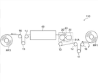
- FIG. 1 is a schematic side view for explaining a method for manufacturing a multilayer film according to an embodiment of the present disclosure.
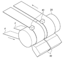
- FIG. 2 is a schematic perspective view showing an enlarged broken line portion shown in FIG.
- FIG. 3 is a schematic plan view showing an enlarged broken line portion shown in FIG.
- FIG. 4 is a schematic side view for explaining a method for manufacturing a multilayer film according to an embodiment of the present disclosure.
- FIG. 5 is a schematic plan view showing an enlarged broken line portion shown in FIG.
- FIG. 6 is a schematic front view for explaining how to use the position control member shown in FIGS. 4 and 5.
- the numerical range indicated by using "-" indicates a range including the numerical values before and after "-" as the lower limit value and the upper limit value, respectively.
- the upper limit value or the lower limit value described in one numerical range may be replaced with the upper limit value or the lower limit value of the numerical range described in another stepwise description.
- the upper limit value or the lower limit value described in a certain numerical range may be replaced with the value shown in the examples.
- the amount of each component in the composition means the total amount of the plurality of substances present in the composition when a plurality of substances corresponding to each component are present in the composition, unless otherwise specified. ..
- process is included in this term not only as an independent process but also as long as the intended purpose of the process is achieved even if it cannot be clearly distinguished from other processes. ..
- solid content means a component other than a solvent.
- the method for producing a multilayer film according to an embodiment of the present disclosure includes simultaneously transporting a plurality of films to a roller including an outer peripheral surface, and the plurality of films conveyed in parallel on the outer peripheral surface of the roller. Includes applying a coating solution to the film.
- a coating solution to the film.
- transporting a plurality of films to a roller including an outer peripheral surface at the same time is referred to as a “conveying process”
- a coating liquid is applied to a plurality of films conveyed in parallel on the outer peripheral surface of the roller.
- “To do” may be referred to as "coating process”.
- a method for producing a multilayer film having excellent productivity is provided.
- the coating liquid is applied to one film conveyed on the outer peripheral surface of the roller, whereas the multilayer film according to the embodiment of the present disclosure is used.
- the coating liquid is applied to a plurality of films conveyed in parallel on the outer peripheral surface of the roller. Therefore, according to one embodiment of the present disclosure, it is presumed that the amount of film processed in the process of applying the coating liquid is increased, and a method for producing a multilayer film having excellent productivity is provided. Further, in terms of productivity, the method for producing a multilayer film according to an embodiment of the present disclosure is considered to have the following advantages as compared with a conventional method (for example, see Patent Document 1 above).
- the width of each film is relatively narrow, so that the wrinkle occurrence rate is reduced.
- the width of the film used it is expected that the loss generated in the downstream process or the process of cutting the film after the coating liquid is applied can be reduced.
- Transfer process a plurality of films are simultaneously transferred to a roller including the outer peripheral surface (hereinafter, may be referred to as “roller CR”).
- Roller CR the outer peripheral surface
- Transporting a plurality of films at the same time means a situation in which at least two films are running.
- roller CR supports a plurality of films conveyed in parallel in the coating process described later.
- the component of the roller CR include a metal.
- the metal include iron and chromium.
- the metal may be an alloy. Examples of the alloy include stainless steel.
- the roller CR may contain one or more metals.
- the outer peripheral surface of the roller CR may be surface-treated.
- Examples of the surface treatment include plating treatment.
- the roller CR may be rotatable.
- the rotatable roller improves the transportability of the film in the coating process described later.
- the width of the roller CR is determined within a range not less than the total value of the widths of a plurality of films conveyed on the outer peripheral surface of the roller CR in the coating process described later.
- the width of the roller CR may be in the range of 1,000 mm to 3,000 mm.
- the diameter of the roller CR is not limited. From the viewpoint of preventing bending and reducing the weight, the diameter of the roller CR is preferably in the range of 50 mm to 500 mm, more preferably in the range of 80 mm to 400 mm, and more preferably in the range of 100 mm to 300 mm. Especially preferable. When the deflection of the roller CR is reduced, for example, the occurrence rate of wrinkles in the film is reduced.
- each film in the plurality of films preferably comprises a polymer and more preferably comprises at least one selected from the group consisting of polyethylene terephthalate, polyethylene naphthalate and triacetyl cellulose.
- each film in the plurality of films preferably comprises a metal, more preferably comprising at least one selected from the group consisting of nickel, titanium, copper, aluminum, silver and gold, copper and It is more preferable to contain at least one selected from the group consisting of aluminum, and it is particularly preferable to contain aluminum.
- the film containing metal include a copper film and an aluminum film.
- the film may have high thermal conductivity.
- Examples of the film having high thermal conductivity include a film having a thermal conductivity of 200 W / (m ⁇ K) or more.
- the upper limit of the thermal conductivity of the film is not limited.
- the thermal conductivity of the film may be 500 W / (m ⁇ K) or less.
- the thermal conductivity of the film is measured using a laser flash method. First, the film is cut out at three points along the width direction (specifically, a position 5 mm from both ends in the width direction and a central portion in the width direction) at a diameter of 5 mm to 10 mm to obtain three measurement samples.
- thermophysical property measuring device for example, LFA-502, Kyoto Denshi Kogyo Co., Ltd.
- the arithmetic mean of the three measurements is taken as the thermal conductivity of the film.
- the layer structure of the film is not limited.
- the film may have a single-layer structure or a multi-layer structure.
- each film in a plurality of films is a long film.
- the length of each film in the plurality of films is preferably 10 m or more, more preferably 100 m or more, and particularly preferably 200 m or more.
- the upper limit of film length is not limited.
- the upper limit of the length of each film in the plurality of films may be 1,000 m or 500 m.
- the length of each film in the plurality of films is usually in the range of 10 m to 1,000 m. "Film length" means the distance from one end of the film to the other in the transport direction of the film.
- the width of the film is not limited. From the viewpoint of improving productivity, a film having a narrow width is preferably used.
- the use of a film having a narrow width (for example, a film having a width close to the width of the product) is used, for example, when the occurrence of wrinkles is suppressed, the process of cutting the film after the coating process is reduced, or a defect is found in the downstream process. Can contribute to the reduction of loss.
- the width of each film in the plurality of films is preferably 1,100 mm or less, more preferably 900 mm or less, and particularly preferably 700 mm or less.
- the lower limit of the width of the film is not limited.
- the lower limit of the width of each film in the plurality of films may be 100 mm or 200 mm.
- the width of each film in the plurality of films is preferably in the range of 100 mm to 1,100 mm, more preferably in the range of 100 mm to 700 mm, and particularly preferably in the range of 200 mm to 700 mm.
- the thickness of the film is not limited. From the viewpoint of preventing deformation (for example, curling and wrinkling) and handling, the thickness of each film in a plurality of films is preferably in the range of 3 ⁇ m to 50 ⁇ m, and preferably in the range of 10 ⁇ m to 30 ⁇ m. More preferred.
- the plurality of films are conveyed using, for example, a known transfer device.
- the transport device may include a tension control mechanism that controls the tension of the film.
- Examples of the transfer device include a transfer roller and a transfer belt.
- examples of the transport device include a delivery device for feeding the film and a winding device for winding the film.
- the sending device and the winding device are also used, for example, as a roll-to-roll type transfer device.
- the roll-to-roll type transport device is preferably used as a device for transporting a long film.
- the transport method by the roll-to-roll method includes, for example, supplying a film from a roll film and winding the film into a roll. The film wound into a roll forms a roll film.
- Roll film means a film rolled into a roll.
- At least one of the delivery device and the take-up device preferably includes a plurality of Tendency Drive Rollers.
- a delivery device including a plurality of tendency-driven rollers can mount a plurality of roll films and supply the film from each roll film.
- a winder including a plurality of tendency-driven rollers can wind a plurality of films at the same time and mount a plurality of roll films.
- the tendency-driven roller is rotated by, for example, a frictional force or a magnetic force acting between a rotating shaft supporting the tendency-driven roller and the tendency-driven roller.
- the axis of rotation is rotated by, for example, a motor.
- a transport device including a tendency-driven roller eg, a delivery device and a take-up device
- a tendency-driven roller can control the tension of the film according to, for example, the rotation speed of the rotating shaft.
- Multiple films may be conveyed at the same or different transfer speeds. It is preferable that the transport speeds of the plurality of films are controlled independently.
- the transport speed of each film in the plurality of films is preferably in the range of 1 m / min to 100 m / min.
- the film in the transport process may be supplied from a roll film.
- the roll film can supply a long film. From the viewpoint of improving productivity, it is preferable that the plurality of films in the transport process are supplied from a plurality of roll films.
- each film in the plurality of films is supplied from a roll film.
- the method for producing a multilayer film according to an embodiment of the present disclosure preferably includes simultaneously supplying the plurality of films by using a delivery device including a plurality of tendency-driven rollers. For example, a plurality of long films are supplied by feeding a film from each roll film in a plurality of roll films arranged along the rotation axis of the delivery device.
- the plurality of films are simultaneously supplied by using a delivery device including a plurality of tendency-driven rollers, and the plurality of films are simultaneously supplied by using the delivery device. It is more preferable to include controlling the tension of each film in the film. It is preferable that the tensions of the plurality of films are controlled independently. Tension control is effective, for example, in a method of supplying a film from a roll film. As the diameter of the roll film decreases with the supply of the film, the appropriate tension may change depending on the diameter of the roll film.
- the film supply method in the transport process is not limited to the above method.
- the plurality of films in the transport step may be supplied by the film splitting step described later.
- Coating process the coating liquid is applied to a plurality of films conveyed in parallel on the outer peripheral surface of the roller CR.
- Productivity is improved by applying the coating liquid to a plurality of films conveyed in parallel on the outer peripheral surface of the roller CR.
- Examples of the coating method include a curtain coating method, a dip coating method, a spin coating method, a printing coating method, a spray coating method, a slot coating method, a roll coating method, a slide coating method, a blade coating method, a gravure coating method and a wire bar method. Can be mentioned.
- the coating step it is preferable to apply the coating liquid by the slot coating method.
- a slot die is used as a coating device.
- the slot die is a coating device including a gap for discharging the coating liquid.
- the slot die may be a known slot die.
- one or more coating devices may be used.
- the thickness of the coating liquid applied to the film (hereinafter, may be referred to as "thickness of liquid film”) is not limited.
- the thickness of the liquid film may be in the range of 10 ⁇ m to 200 ⁇ m.
- the thickness of the liquid film may be in the range of 20 ⁇ m to 100 ⁇ m.
- the type of coating liquid is not limited.
- the type of coating liquid is determined, for example, according to the use of the multilayer film.
- the coating liquid is preferably a water-based coating liquid.
- the "water-based coating liquid” means a coating liquid in which the solvent contained in the coating liquid is substantially water.
- the solvent contained in the coating liquid is substantially water means that water occupies most of the solvent contained in the coating liquid.
- the ratio of water to the solvent contained in the water-based coating liquid is preferably 90% by mass or more, more preferably 95% by mass or more, and particularly preferably 100% by mass.
- Examples of the water contained in the water-based coating liquid include natural water, purified water, distilled water, ion-exchanged water, pure water and ultrapure water.
- the water content in the water-based coating liquid is preferably 40% by mass or more, more preferably 50% by mass or more, based on the total mass of the water-based coating liquid.
- the water content in the water-based coating liquid is preferably less than 100% by mass, more preferably 80% by mass or less, based on the total mass of the water-based coating liquid.
- the water-based coating liquid may contain particles.
- the particles include inorganic particles, organic particles, and composite particles of an inorganic substance and an organic substance.
- Examples of the inorganic particles include metal particles, semi-metal particles, metal compound particles, semi-metal compound particles, inorganic pigment particles, mineral particles and polycrystalline diamond particles.
- Examples of the metal include alkali metals, alkaline earth metals, transition metals and alloys thereof.
- Examples of metalloids include silicon.
- Examples of metal compounds and metalloid compounds include oxides, hydroxides and nitrides.
- Examples of the inorganic pigment include carbon black. Examples of minerals include mica.
- organic particles examples include resin particles and organic pigment particles.
- Examples of the composite particles of the inorganic substance and the organic substance include composite particles in which the inorganic particles are dispersed in a matrix made of the organic substance, composite particles in which the periphery of the organic particles is coated with the inorganic substance, and the periphery of the inorganic particles is the organic substance. Examples thereof include composite particles coated with.
- the particles may be surface-treated to impart dispersibility.
- Composite particles may be formed by surface treatment.
- the particle size, specific gravity and usage pattern of the particles are not limited.
- the particle size, specific gravity, and usage pattern of the particles are determined, for example, according to the coating film formed by the coating liquid and the production conditions of the coating film.
- the water-based coating liquid may contain one kind or two or more kinds of particles.
- the content of particles in the water-based coating liquid is not limited.
- the content of particles in the water-based coating liquid is determined, for example, according to the purpose of adding the particles, the coating film formed by the coating liquid, and the production conditions of the coating film.
- the components of the water-based coating liquid include a binder component, a component that contributes to the dispersibility of particles, a polymerizable compound, a polymerization initiator, and a component for enhancing coating performance (for example, a surfactant).
- the solid content concentration of the coating liquid is preferably less than 70% by mass, more preferably 30% by mass to 60% by mass.
- the method for producing a multilayer film according to an embodiment of the present disclosure may include steps other than the above-mentioned steps, if necessary.
- the method for producing a multilayer film according to an embodiment of the present disclosure is to divide one film into a plurality of films (hereinafter, referred to as "film division step” in this paragraph), and to put a plurality of films on a roller CR.
- Simultaneous transport ie, transport process
- the plurality of films may be supplied by dividing one film.
- a plurality of films may be supplied from the plurality of roll films.
- the film dividing step may be carried out in a series of steps including a transfer step and a coating step.
- a film division step, a transfer step, and a coating step may be performed between the supply of the rolled film and the winding of the film.
- the film splitting step may be performed in the vicinity of the roller CR.
- the plurality of films may be transported in parallel on the outer peripheral surface of the roller CR.
- the method of dividing the film include a method of cutting the film using a blade.
- one film can be divided into a plurality of films by cutting one film along the transport direction using a blade.
- the film dividing step may be carried out while transporting the film.
- the method for producing a multilayer film according to an embodiment of the present disclosure may include drying the coating liquid after the coating step.
- Examples of the drying method include heating and blowing.
- the temperature of the gas in the blast is preferably in the range of 25 ° C to 200 ° C, more preferably in the range of 30 ° C to 150 ° C.
- the wind speed in blowing air is preferably 1.5 m / sec to 50 m / sec.
- the drying device used for drying the coating liquid include an oven, a hot air blower, and an infrared heater.
- the method for producing a multilayer film according to an embodiment of the present disclosure is to detect the position of one end in the width direction of each film in a plurality of films coated with a coating liquid, and in the plurality of films according to the above positions. It is preferable to include controlling the transport position of each film.
- the method as described above suppresses meandering of the film and improves the accuracy of the coating position of the coating liquid in the width direction of the film. As a result, the coating liquid is applied to a desired range of the film. In the above method, not only the positions of one end in the width direction of the film but also the positions of both ends in the width direction of the film may be detected.
- the method of detecting the position of the film is not limited.
- the position of the film is detected using, for example, a known sensor.
- the sensor include a two-dimensional laser displacement sensor and an image sensor. It is preferable that the sensor is arranged facing the roller CR downstream from the coating position of the coating liquid in the transport direction of the plurality of films.
- the sensor arranged as described above detects the position of one end in the width direction of the film immediately after the coating process, and improves the accuracy of the coating position of the coating liquid in the width direction of the film.
- the method of controlling the film transport position is not limited.
- the film transport position is controlled using, for example, a known edge position control (EPC) device.
- the EPC device is known as a device that suppresses meandering of the film while detecting the position of the edge of the film.
- each film in the plurality of films is arranged with the roller CR and facing the roller CR upstream of the coating position of the coating liquid in the transport direction of the plurality of films, and the transport position of the films is controlled. It is preferable to include changing at least one of the pressure and the angle of the position control member while passing it between the position control member to be controlled.
- the method as described above improves the controllability of the transport position of the film and the accuracy of the coating position of the coating liquid in the width direction of the film.
- the pressure of the position control member is the pressure applied to the film by the position control member.
- the film can be moved left or right with respect to the film transport direction according to the change in the pressure of the position control member.
- the amount of change in the pressure of the position control member may be in the range of 0.01 MPa to 0.5 MPa.
- the angle of the position control member is the angle of the position control member with respect to the transport direction of the film in a plan view. The film can be moved left or right with respect to the film transport direction according to the change in the angle of the position control member.
- the amount of change in the angle of the position control member may be within the range of ⁇ 1 degree. Specific examples of how to use the position control member are described in the section of "Production method" below.
- the control of the transport position preferably includes contacting the position control member with at least a part of each film in the plurality of films. It is more preferable that the control of the transport position includes bringing the position control member into contact with a part of each film in the plurality of films. It is particularly preferable that the control of the transport position includes contacting the position control member with at least a part of the widthwise end region of each film in the plurality of films. The method as described above improves the controllability of the transport position of the film and improves the accuracy of the coating position of the coating liquid in the width direction of the film.
- the "film widthwise edge region” extends in the length direction of the film (that is, the film transport direction) and has a predetermined width from the edge of the film toward the center of the film in the width direction of the film. It is an area to have.
- the widthwise edge region may be defined in the vicinity of one end in the widthwise direction of the film or in the vicinity of both ends in the widthwise direction of the film. From the viewpoint of improving the controllability of the transport position of the film, the width of the edge region in the width direction of the film is preferably 1/3 of the width of the film, and more preferably 1/4 of the width of the film. It is particularly preferable that it is 1/5 of the width of the film.
- the position control member may be rotatable.
- the rotatable position control member improves the transportability of the film.
- the shape of the position control member examples include a cylinder and a truncated cone.
- the angle between the bottom surface and the side surface is preferably 60 degrees to 87 degrees.
- the term "bottom" means the face with the largest diameter of the two circular planes contained in the truncated cone.
- the diameter of the position control member is preferably in the range of 10 mm to 100 mm. From the viewpoint of improving the controllability of the film transport position, the diameter of the position control member is preferably smaller than the diameter of the roller CR.
- the width of the position control member is preferably in the range of 5 mm to 100 mm, and more preferably in the range of 10 mm to 50 mm.
- the ratio of the width of the position control member to the width of the film is preferably in the range of 1/100 to 1/5, and 1/80 to 1/8. It is more preferably within the range of 1/50 to 1/10, and particularly preferably within the range of 1/50 to 1/10.
- the ratio of the width of the position control member to the width of the film is calculated based on the width of the film to be measured and the width of the position control member in contact with the film to be measured.
- the ratio of the width of the position control member to the width of the roller CR is preferably in the range of 1/500 to 1/10, and 1/200 to 1/10. It is more preferably in the range of 20, and particularly preferably in the range of 1/100 to 1/30.
- the number of position control members is determined, for example, according to the number of film rows in a plurality of films conveyed in parallel on the outer peripheral surface of the roller CR.
- the number of position control members may be the same as the number of film rows in a plurality of films conveyed in parallel on the outer peripheral surface of the roller CR.
- the number of position control members may exceed the number of film rows in a plurality of films conveyed in parallel on the outer peripheral surface of the roller CR. From the viewpoint of improving the controllability of the film transport position, the number of position control members is preferably equal to or larger than the number of film rows in a plurality of films transported in parallel on the outer peripheral surface of the roller CR.
- the number of position control members in contact with each film in a plurality of films transported in parallel on the outer peripheral surface of the roller CR is at least one. Is preferable, and one or two is preferable.
- Examples of the components of the position control member include polymers and metals.
- Examples of the polymer include polyurethane, acrylonitrile-butadiene rubber (abbreviation: NBR), ethylene-propylene-diene rubber (abbreviation: EPDM) and fluororubber.
- the position control member may contain one kind or two or more kinds of polymers.
- Examples of the metal include iron and chromium.
- the metal may be an alloy. Examples of the alloy include stainless steel.
- the position control member may contain one kind or two or more kinds of metals.
- the position control member may be formed from a plurality of components.
- the position control member preferably has elasticity.
- the elastic position control member improves the controllability of the film transport position.
- Examples of the component of the position control member having elasticity include rubber.
- the rubber may be natural rubber or synthetic rubber. Examples of the rubber include urethane rubber, acrylonitrile-butadiene rubber (abbreviation: NBR), ethylene-propylene-diene rubber (abbreviation: EPDM), and fluororubber.
- the position control member preferably contains at least one selected from the group consisting of urethane rubber, acrylonitrile-butadiene rubber, ethylene-propylene-diene rubber and fluorine rubber.
- the hardness of the rubber is preferably 20 to 90 degrees, more preferably 30 to 80 degrees.
- the position control member may include a rubber layer.
- the rubber layer may be arranged so as to cover at least a part of the surface of any member (for example, a metal member) constituting the position control member.
- the position control member preferably includes a rubber layer as a surface layer. The thickness of the rubber layer is preferably in the range of 1 mm to 50 mm, more preferably in the range of 2 mm to 20 mm.
- the method for producing a multilayer film according to an embodiment of the present disclosure preferably includes controlling the tension of each film in a plurality of films. It is preferable that the tensions of the plurality of films are controlled independently. Tension control contributes to the uniform application of the coating liquid. In addition, tension control is effective, for example, in a method in which each film is supplied from a roll film. As the diameter of the roll film decreases over time, the appropriate tension may change depending on the diameter of the roll film. Therefore, by controlling the tension of the film according to the change in the diameter of the roll film, it is possible to suppress the occurrence of coating unevenness.
- the tension of each film in the plurality of films is preferably in the range of 30 N / m to 300 N / m, and more preferably in the range of 150 N / m to 250 N / m.
- Tension control is performed using, for example, a known tension control device.
- Tension control may be performed using a known transfer device including a tension control mechanism.
- Tension control may be performed using at least one of a delivery device and a take-up device.
- Preferred delivery device includes, for example, a delivery device including a plurality of tendency-driven rollers described in the above section “Transporting process”.
- Preferred take-up devices include, for example, take-up devices including a plurality of tendency-driven rollers described in the above section "Transportation Steps".
- the method for producing a multilayer film according to an embodiment of the present disclosure may include simultaneously winding the plurality of films coated with the coating liquid by using a winding device including a plurality of tendency-driven rollers. preferable.
- a winding device including a plurality of tendency-driven rollers for example, by arranging a plurality of roll films along the rotation axis of the winding device, a plurality of roll films can be mounted on the winding device.
- Techniques for tendency-driven rollers are described in the "Transfer Process" section above.
- the method for producing a multilayer film according to an embodiment of the present disclosure is to simultaneously wind the plurality of films coated with the coating liquid by using a winding device including a plurality of tendency-driven rollers, and to wind the film. It is more preferable to include controlling the tension of each film in the plurality of films by using a taking device.
- the method for producing a multilayer film according to an embodiment of the present disclosure may include a step of cutting the multilayer film.
- the width of the multilayer film can be adjusted by cutting the multilayer film.
- Examples of the method for cutting the multilayer film include a method using a blade.
- the method for producing a multilayer film according to one embodiment of the present disclosure is preferably carried out by a roll-to-roll method.
- the method for producing a multilayer film carried out by the roll-to-roll method at least a transfer step and a coating step are carried out between the supply of the rolled film and the winding of the film.
- FIG. 1 is a schematic side view for explaining a method for manufacturing a multilayer film according to an embodiment of the present disclosure.
- FIG. 2 is a schematic perspective view showing an enlarged broken line portion shown in FIG.
- FIG. 3 is a schematic plan view showing an enlarged broken line portion shown in FIG.
- the manufacturing apparatus 100 shown in FIG. 1 includes a transfer roller 10, a transfer roller 11, a transfer roller 12, a transfer roller 13, a transfer roller 14, a transfer roller 15, a transfer roller 16, a backup roller 20, a slot die 30, a sensor 40, and a position. It includes a control member 50, a drying device 60, a sending device (not shown), and a winding device (not shown).
- the transfer roller 10, the transfer roller 11, the transfer roller 12, the transfer roller 13, the transfer roller 14, the transfer roller 15, the transfer roller 16, and the backup roller 20 transfer the film F while supporting the film F.
- Each roller is rotatable.
- the backup roller 20 corresponds to the roller CR described above.
- the slot die 30 discharges the coating liquid onto the film F.
- the coating liquid is supplied from a liquid feeding device (not shown) connected to the slot die 30.
- a liquid feeding device not shown
- two slot dies 30 are used. As shown in FIGS. 2 and 3, the two slot dies 30 are aligned along the width direction of the backup roller 20. Each slot die 30 is arranged to face the backup roller 20. Instead of the two slot dies 30, one slot die capable of discharging the coating liquid onto the two films F may be used.
- the sensor 40 detects the position of one end of the film F in the width direction.
- two sensors 40 are used. As shown in FIG. 2, the two sensors 40 are aligned along the width direction of the backup roller 20. Each sensor 40 is arranged facing the backup roller 20 downstream of the application position of the coating liquid discharged from the slot die 30 in the transport direction of the film F.
- the position control member 50 controls the transport position of the film F according to the position of the film F detected by using the sensor 40.
- two position control members 50 are used. As shown in FIG. 3, the two position control members 50 are arranged along the width direction of the backup roller 20. Each position control member 50 is arranged facing the backup roller 20 upstream of the application position of the coating liquid discharged from the slot die 30 in the transport direction of the film F. Each position control member 50 is in contact with at least a part of the widthwise end region of the film F.
- the shape of each position control member 50 is a cylinder. Each position control member 50 is rotatable. The straight line passing through the center of the rotational movement of each position control member 50 is parallel to the width direction of the backup roller 20.
- the drying device 60 dries the coating liquid applied to the film F.
- the delivery device (not shown) supplies the film F from the roll film RF1.
- the delivery device includes a plurality of tendency-driven rollers rotatably supported on the outer circumference of the rotating shaft.
- the delivery device mounts two roll films RF1 along a rotation axis extending from the front to the back of FIG. 1.
- the winding device (not shown) winds the multilayer film containing the film F into a roll to form the roll film RF2.
- the take-up device includes a plurality of tendency-driven rollers rotatably supported on the outer circumference of the rotating shaft.
- the take-up device mounts two roll films RF2 along a rotation axis extending from the front to the back of FIG. 1.
- the method for manufacturing the multilayer film shown in FIG. 1 is carried out by a roll-to-roll method.
- two roll films RF1 are used.
- the two roll films RF1 are lined up from the front to the back of FIG.
- Each roll film RF1 supplies film F.
- the film F sent out from each roll film RF1 passes through the transfer roller 10, the transfer roller 11, the transfer roller 12, the transfer roller 13, the backup roller 20, the drying device 60, the transfer roller 14, the transfer roller 15, and the transfer roller 16. , Rolled up.
- two long films F are conveyed in parallel at the same time.
- the two films F that have reached the backup roller 20 are conveyed in parallel along the outer peripheral surface of the backup roller 20.
- the two films F are arranged along the width direction of the backup roller 20.
- the number of films arranged on the outer peripheral surface of the backup roller 20, that is, the number of film rows is two.
- the coating liquid discharged from the slot die 30 is applied to the two films F conveyed in parallel on the outer peripheral surface of the backup roller 20.
- productivity is improved by applying the coating liquid to the two films F while transporting the two films F in parallel on one backup roller 20. .. Further, by applying the coating liquid to the two films F on one backup roller 20, the cost required for the manufacturing equipment can be expected to be reduced.
- the transport position of the film F is controlled by changing the angle of the position control member 50 while passing the film F between the backup roller 20 and the position control member 50. ing.
- the angle of the position control member 50 is feedback-controlled by a linear motor (not shown) according to the position of the film F detected by the sensor 40.
- a linear motor not shown
- FIG. 3 when the position control member 50 is tilted clockwise with respect to the transport direction of the film F, the film F can move to the right, and when the position control member 50 is tilted counterclockwise with respect to the transport direction of the film F, the film is formed. F can move to the left.
- the coating liquid applied to the film F is dried in the drying device 60.
- a multilayer film is formed by drying the coating liquid.
- the multilayer film is wound into a roll using a winding device (not shown).
- two roll films RF2 are formed along the rotation axis of a winding device (not shown) from the front to the back of FIG.
- FIG. 4 is a schematic side view for explaining a method for manufacturing a multilayer film according to an embodiment of the present disclosure.
- FIG. 5 is a schematic plan view showing an enlarged broken line portion shown in FIG.
- FIG. 6 is a schematic front view for explaining how to use the position control member shown in FIGS. 4 and 5.
- the manufacturing apparatus 110 shown in FIG. 4 includes the same components as the components in the manufacturing apparatus 100 shown in FIG. 1, except for the position control member. Further, the method for manufacturing the multilayer film shown in FIG. 4 is the same as the method for manufacturing the multilayer film shown in FIG. 1, except for the method for controlling the transport position of the film F.
- the position control member 51A and the position control member 51B control the transport position of the film F according to the position of the film F detected by using the sensor 40.
- two sets of position control members 51A and position control members 51B are used.
- the position control member 51A and the position control member 51B are arranged along the width direction of the backup roller 20.
- the position control member 51A and the position control member 51B are arranged so as to face the backup roller 20 upstream of the application position of the coating liquid discharged from the slot die 30 in the transport direction of the film F.
- the shape of the position control member 51A and the position control member 51B is a truncated cone.
- the position control member 51A and the position control member 51B are rotatable. The straight line passing through the center of the rotational movement of the position control member 51A and the position control member 51B is parallel to the width direction of the backup roller 20.
- the position control member 51A and the position control member 51B are arranged along the direction X.
- the direction X is parallel to the width direction of the backup roller 20.
- the position control member 51A and the position control member 51B can move along the direction Y by an air cylinder (not shown) and can contact at least a part of the widthwise end region of the film F.
- the position control member 51A can be in contact with the vicinity of one end of the film, and the position control member 51B can be in contact with the vicinity of the other end of the film.
- the film F is conveyed from the front to the back of FIG.
- the pressures of the position control member 51A and the position control member 51B are feedback controlled by an air cylinder (not shown) according to the position of the film F detected by the sensor 40.
- the film F when the pressure of the position control member 51B becomes larger than the pressure of the position control member 51A, the film F can move to the right, and when the pressure of the position control member 51A becomes larger than the pressure of the position control member 51B, the film F moves to the left. You can move to.
- the film F may be moved to the right by bringing only the position control member 51B into contact with the film F.
- the film F may be moved to the left by bringing only the position control member 51A into contact with the film F.
- Example 1 (Preparation of film) An aluminum film having a width of 600 mm, a thickness of 10 ⁇ m, a length of 300 m and a thermal conductivity of 230 W / (m ⁇ K) was prepared. The aluminum film is rolled into a roll to form a roll film. In Example 1, two roll films were prepared.
- the aqueous dispersion of Art Pearl J-7P was prepared by the following method. To 74 parts by mass of pure water, 3 parts by mass of Emarex 710 (Nippon Emulsion Co., Ltd., nonionic surfactant) and 3 parts by mass of sodium carboxymethyl cellulose (Daiichi Kogyo Seiyaku Co., Ltd.) were added. To the obtained aqueous solution, 20 parts by mass of Art Pearl J-7P (Negami Kogyo Co., Ltd., silica composite crosslinked acrylic resin fine particles) was added, and 10,000 rpm (revolutions per minute) was added using an ace homogenizer (Nissei Tokyo Office Co., Ltd.).
- the coating liquid A was applied to the film using a manufacturing apparatus including the components as shown in FIG. 1, and then the coating liquid was dried.
- a multilayer film was obtained by the above procedure.
- the transport speed of the film is 20 m / min.
- the diameter of the backup roller is 200 mm. Specific manufacturing conditions are shown in Table 1.
- Example 2 A multilayer film was obtained by the same procedure as in Example 1 except that the production conditions were changed according to the description in Table 1.
- Example 3> A multilayer film was obtained by the same procedure as in Example 1 except that the manufacturing apparatus including the constituent elements as shown in FIG. 4 was used instead of the manufacturing apparatus including the constituent elements as shown in FIG.
- Example 4 A multilayer film was obtained by the same procedure as in Example 3 except that the production conditions were changed according to the description in Table 1.
- the appearance of the obtained multilayer film was visually confirmed and evaluated according to the following criteria.
- the "coating position” in the following criteria means the distance from the edge of the film to the edge of the coating film in the width direction.
- the evaluation results are shown in Table 1.
- the "angle” described in the column of "control of transport position” in Table 1 means that the transport position of the film was controlled by using the change in the angle of the position control member as shown in FIG.
- the position control member used in the above control method is a columnar roller.
- the diameter of the columnar roller is 80 mm.
- the width of the columnar roller is 20 mm.
- a rubber layer is formed on the outer peripheral surface of the columnar roller.
- the thickness of the rubber layer is 20 mm.
- the rubber layer contains acrylonitrile-butadiene rubber.
- the hardness of acrylonitrile-butadiene rubber is 70 degrees.
- the width of the edge region in the width direction of the film in the above control method is 1/5 of the width of the film.
- the "pressure” described in the column of "control of transport position” in Table 1 means that the transport position of the film was controlled by using the change in the pressure of the position control member as shown in FIG.
- the position control member used in the above control method is a truncated cone-shaped roller.
- the diameter of the truncated cone-shaped roller is 80 mm.
- the width of the truncated cone-shaped roller is 50 mm.
- a rubber layer is formed on the outer peripheral surface of the truncated cone-shaped roller.
- the thickness of the rubber layer is 20 mm.
- the rubber layer contains urethane rubber.
- the hardness of urethane rubber is 40 degrees.
- the width of the edge region in the width direction of the film in the above control method is 1/5 of the width of the film.
- Table 1 shows that a multilayer film was obtained by a method of applying a coating liquid to a plurality of films conveyed in parallel on the outer peripheral surface of the backup roller. Further, Table 1 shows that the accuracy of the coating position of the coating liquid in the width direction of the film is improved by controlling the transport position of each film. Further, Table 1 shows that the occurrence of wrinkles was suppressed even when the total value of the widths of the plurality of films used in Examples 1 to 4 was the same as the width of the films used in Comparative Example 1. show.
- Conveying roller 20 Backup roller 30: Slot die 40: Sensor 50, 51A, 51B: Position control member 60: Drying device 100, 110: Manufacturing device F: Film RF1 , RF2: Roll film
Landscapes
- Application Of Or Painting With Fluid Materials (AREA)
Priority Applications (2)
| Application Number | Priority Date | Filing Date | Title |
|---|---|---|---|
| JP2022566818A JP7832121B2 (ja) | 2020-12-03 | 2021-11-12 | 多層フィルムの製造方法 |
| CN202180081114.1A CN116529188A (zh) | 2020-12-03 | 2021-11-12 | 多层膜的制造方法 |
Applications Claiming Priority (2)
| Application Number | Priority Date | Filing Date | Title |
|---|---|---|---|
| JP2020-201156 | 2020-12-03 | ||
| JP2020201156 | 2020-12-03 |
Publications (1)
| Publication Number | Publication Date |
|---|---|
| WO2022118637A1 true WO2022118637A1 (ja) | 2022-06-09 |
Family
ID=81853703
Family Applications (1)
| Application Number | Title | Priority Date | Filing Date |
|---|---|---|---|
| PCT/JP2021/041768 Ceased WO2022118637A1 (ja) | 2020-12-03 | 2021-11-12 | 多層フィルムの製造方法 |
Country Status (3)
| Country | Link |
|---|---|
| JP (1) | JP7832121B2 (https=) |
| CN (1) | CN116529188A (https=) |
| WO (1) | WO2022118637A1 (https=) |
Citations (4)
| Publication number | Priority date | Publication date | Assignee | Title |
|---|---|---|---|---|
| JP2002028554A (ja) * | 2000-07-14 | 2002-01-29 | Konica Corp | 塗布方法及び塗布装置jp5 |
| JP2004333616A (ja) * | 2003-05-01 | 2004-11-25 | Fuji Photo Film Co Ltd | 感光性樹脂転写装置および方法 |
| JP2009240925A (ja) * | 2008-03-31 | 2009-10-22 | Fujifilm Corp | 液体塗布装置、液体塗布方法、インクジェット記録装置、及びインクジェット記録方法 |
| JP2014213221A (ja) * | 2013-04-23 | 2014-11-17 | コニカミノルタ株式会社 | 機能性フィルムの製造方法 |
Family Cites Families (10)
| Publication number | Priority date | Publication date | Assignee | Title |
|---|---|---|---|---|
| JPS57195645A (en) * | 1981-05-27 | 1982-12-01 | Keiwa Shoko Kk | Tape-shaped base material juxtaposed body and its manufacture |
| JP2007219020A (ja) | 2006-02-14 | 2007-08-30 | Fujifilm Corp | 樹脂積層体及びその製造方法、表示装置用材料、並びに表示装置及び液晶表示装置 |
| JP2007334095A (ja) | 2006-06-16 | 2007-12-27 | Fujifilm Corp | 樹脂積層体の製造方法、樹脂積層体、表示装置用材料、表示装置、及び液晶表示装置 |
| JP5201490B2 (ja) * | 2008-12-24 | 2013-06-05 | 富士電機株式会社 | 可撓性基板の処理装置および薄膜積層体の製造装置 |
| JP2010215371A (ja) * | 2009-03-17 | 2010-09-30 | Fuji Electric Holdings Co Ltd | 帯状可撓性基板搬送システムおよびそれに用いる搬送位置制御装置 |
| JP5293498B2 (ja) | 2009-08-21 | 2013-09-18 | トヨタ自動車株式会社 | ウエブ搬送装置及びその方法と電池の製造方法 |
| JP2011171483A (ja) * | 2010-02-18 | 2011-09-01 | Fuji Electric Co Ltd | 薄膜太陽電池および可撓性基板の製造方法ならびに可撓性基板の処理装置 |
| JP6232189B2 (ja) * | 2013-02-21 | 2017-11-15 | 日東電工株式会社 | 光学フィルムの製造方法 |
| JP6632280B2 (ja) | 2015-09-14 | 2020-01-22 | 株式会社Screenホールディングス | 塗工装置 |
| KR102485873B1 (ko) * | 2018-12-21 | 2023-01-06 | 주식회사 엘지화학 | 동박 필름 제조 방법 및 장치 |
-
2021
- 2021-11-12 JP JP2022566818A patent/JP7832121B2/ja active Active
- 2021-11-12 CN CN202180081114.1A patent/CN116529188A/zh active Pending
- 2021-11-12 WO PCT/JP2021/041768 patent/WO2022118637A1/ja not_active Ceased
Patent Citations (4)
| Publication number | Priority date | Publication date | Assignee | Title |
|---|---|---|---|---|
| JP2002028554A (ja) * | 2000-07-14 | 2002-01-29 | Konica Corp | 塗布方法及び塗布装置jp5 |
| JP2004333616A (ja) * | 2003-05-01 | 2004-11-25 | Fuji Photo Film Co Ltd | 感光性樹脂転写装置および方法 |
| JP2009240925A (ja) * | 2008-03-31 | 2009-10-22 | Fujifilm Corp | 液体塗布装置、液体塗布方法、インクジェット記録装置、及びインクジェット記録方法 |
| JP2014213221A (ja) * | 2013-04-23 | 2014-11-17 | コニカミノルタ株式会社 | 機能性フィルムの製造方法 |
Also Published As
| Publication number | Publication date |
|---|---|
| JP7832121B2 (ja) | 2026-03-17 |
| CN116529188A (zh) | 2023-08-01 |
| JPWO2022118637A1 (https=) | 2022-06-09 |
Similar Documents
| Publication | Publication Date | Title |
|---|---|---|
| EP3307443B1 (en) | Liquid coating method and apparatus with a deformable metal roll | |
| JP5688858B2 (ja) | 機能性フィルムの製造方法、及びウエブ搬送装置 | |
| EP1579927A2 (en) | Coating apparatus and coating method | |
| CN101275809B (zh) | 料片引导辊、料片引导装置及引导料片的方法 | |
| JP2009203055A (ja) | ウェブロールの製造方法 | |
| WO2022118637A1 (ja) | 多層フィルムの製造方法 | |
| CN117798034A (zh) | 涂布膜的制造方法 | |
| CN116600905B (zh) | 多层膜的制造方法及涂布装置 | |
| CN115397568B (zh) | 涂布膜的制造方法 | |
| WO2023145842A1 (ja) | 乾燥装置及び乾燥方法 | |
| WO2023008479A1 (ja) | 塗工膜の製造方法 | |
| JP7674400B2 (ja) | 表面処理装置及び表面処理方法 | |
| JP3135176B2 (ja) | フィルム材の搬送装置 | |
| JP6172063B2 (ja) | 長尺樹脂フィルムの表面処理装置 | |
| KR20220123500A (ko) | 초고속 용사로 제조된 그라비아 롤 인쇄 유닛 및 이를 이용한 인쇄 방법 | |
| JP7812804B2 (ja) | 積層体の製造方法 | |
| JP7758689B2 (ja) | 積層体の製造方法 | |
| JP2009136712A (ja) | 塗布方法及び装置 | |
| WO2025047198A1 (ja) | 塗工膜の製造方法 | |
| JP6036608B2 (ja) | 塗工装置 | |
| JP2005046751A (ja) | 乾燥装置および乾燥方法 | |
| JP2004230352A (ja) | バーコータおよび塗布方法 | |
| JP2025167196A (ja) | 乾燥装置 | |
| JP2001038277A (ja) | 幅出し装置 | |
| EP4084913A1 (en) | Die coating on air supported shell |
Legal Events
| Date | Code | Title | Description |
|---|---|---|---|
| 121 | Ep: the epo has been informed by wipo that ep was designated in this application |
Ref document number: 21900392 Country of ref document: EP Kind code of ref document: A1 |
|
| ENP | Entry into the national phase |
Ref document number: 2022566818 Country of ref document: JP Kind code of ref document: A |
|
| WWE | Wipo information: entry into national phase |
Ref document number: 202180081114.1 Country of ref document: CN |
|
| NENP | Non-entry into the national phase |
Ref country code: DE |
|
| 122 | Ep: pct application non-entry in european phase |
Ref document number: 21900392 Country of ref document: EP Kind code of ref document: A1 |